Review

Optimizing Power Flow and Stability in Hybrid AC/DC Microgrids: AC, DC, and Combined Analysis

by
Ghanshyam Meena
1,
Veerpratap Meena
2,*,
Akhilesh Mathur
1,
Vinay Pratap Singh
1,
Ahmad Taher Azar
3,4,5,* and
Ibrahim A. Hameed
6,*
1
Department of Electrical Engineering, Malaviya National Institute of Technology, Jaipur 302017, Rajasthan, India
2
Department of Electrical Engineering, National Institute of Technology Jamshedpur, Jamshedpur 831014, Jharkhand, India
3
College of Computer and Information Sciences, Prince Sultan University, Riyadh 11586, Saudi Arabia
4
Automated Systems and Soft Computing Lab (ASSCL), Prince Sultan University, Riyadh 11586, Saudi Arabia
5
Faculty of Computers and Artificial Intelligence, Benha University, Benha 13518, Egypt
6
Department of ICT and Natural Sciences, Norwegian University of Science and Technology, Larsgårdsvegen 2, 6009 Ålesund, Norway
*
Authors to whom correspondence should be addressed.
Math. Comput. Appl. 2024, 29(6), 108; https://doi.org/10.3390/mca29060108
Submission received: 2 October 2024 / Revised: 17 November 2024 / Accepted: 22 November 2024 / Published: 24 November 2024
(This article belongs to the Special Issue Applied Optimization in Automatic Control and Systems Engineering)

Abstract

:
A microgrid (MG) is a unique area of a power distribution network that combines distributed generators (conventional as well as renewable power sources) and energy storage systems. Due to the integration of renewable generation sources, microgrids have become more unpredictable. MGs can operate in two different modes, namely, grid-connected and islanded modes. MGs face various challenges of voltage variations, frequency deviations, harmonics, unbalances, etc., due to the uncertain behavior of renewable sources. To study the impact of these issues, it is necessary to analyze the behavior of the MG system under normal and abnormal operating conditions. Two different tools are used for the analysis of microgrids under normal and abnormal conditions, namely, power flow and short-circuit analysis, respectively. Power flow analysis is used to determine the voltages, currents, and real and reactive power flow in the MG system under normal operating conditions. Short-circuit analysis is carried out to analyze the behavior of MGs under faulty conditions. In this paper, a review of power flow and short-circuit analysis algorithms for MG systems under two different modes of operation, grid-connected and islanded, is presented. This paper also presents a comparison of various power flow as well as short-circuit analysis techniques for MGs in tabular form. The modeling of different components of MGs is also discussed in this paper.

1. Introduction

Recently, the penetration of distributed energy resources (DERs) has expanded, and renewable energy resources are the forefront of these. The combination of distributed generation (DG) penetration and the development of active distribution networks (ADNs) has led to a growing interest in microgrids (MGs). MGs can effectively integrate DGs, energy storage, and advanced control systems to create localized and resilient energy systems. In comparison to traditional AC networks, DC MGs have many advantages:
  • System efficiency is high because fewer conversion stages are necessary to connect electronic and nonlinear loads.
  • More cost-effective energy storage and DG units based on DC, such as solar and fuel cells.
  • More appropriate and efficient methods for DC loads, like LED lighting and electric vehicles (EVs).
  • Small connecting interface with AC grids because of no synchronization and also has a more flexible energy paradigm for future expansion.
A small network made from these DGs is called an MG. An MG consists of DGs, distribution lines (AC and DC), distributed loads, energy storage systems (ESSs), etc. A hybrid MG is a promising solution for smart grid implementation in conventional distribution networks. It brings together the benefits of both AC and DC MG distribution systems, enabling direct integration of energy resources, loads, and ESSs [1,2]. A comparison of different existing review papers is presented in Table 1. This table focuses on a comparison of the existing review papers regarding the various architectures (AC, DC, and hybrid AC/DC) of microgrids. The table uses a check mark (✓) to indicate that a particular aspect is covered in a specific reference, and a cross mark (×) indicates that part is not covered in that reference regarding the microgrid architectures, interlinking converters (ILCs), power flow analysis (PFA), and short-circuit analysis (SCA). ILCs are essential to integrating AC and DC microgrid systems. Table 1 includes every aspect (AC, DC, AC/DC structures, ILC, PFA, and SCA), providing a more comprehensive review than most previous reviews, which frequently overlooked one or more components.
Power flow studies are critical in the planning and design of future power system growth. Deregulation in the system has increased interest in rising DG penetration, which can meet the requirements of local loads on its own. It is a vital technique for studying the system’s functioning. For optimal system reliability and efficiency, operators should conduct power flow assessments of MGs [13]. MGs can operate in islanded mode or be connected to a grid. The main grid maintains the system’s voltage and frequency in grid-linked mode; however, in islanded mode, the system’s voltage and frequency are not constant due to the absence of a slack bus [14,15].
Since the 1950s, conventional algorithms of power flow such as backward/forward sweep (BFS), Newton–Raphson, and Gauss–Seidel have been extensively used in AC systems. In the islanded mode of operation, droop-controlled DGs increase the computational difficulty of power flow for voltage and frequency regulation, and most of the conventional approaches are invalid. Analysis of islanded MGs’ power flow is shown to have been achieved by various modified or latest-load flow techniques in the literature review section. In [16], load flows for an island MG are solved using the usual approach, where the DG of greatest rating is selected as the slack node, and the rest of the DGs are represented as PQ or PV buses. The approach assumes that an islanded MG’s frequency is constant.
In a power system, different types of faults exist; these faults can be symmetrical or unsymmetrical. Symmetrical faults are usually considered three-phase faults. Unsymmetrical faults include line-to-ground (L-G), line-to-line (L-L), and double line-to-ground (LL-G) faults [17]. In the case of MG systems, the probability of a symmetrical fault occurring is very low, and unsymmetrical faults occur in most cases. The L-G fault is the most probable kind of fault in the electrical system. All probable faults must be tested for potential breaches of relay sensitivity, fuse breaking capability, and earth fault current levels. Therefore, online SCA methods should ideally meet two fundamental requirements: rapidity and precision. Modeling of the components used for SCA is described in reference [18].
The online process of fault analysis is typically performed periodically, either automatically or in response to a request for topology adjustment. Many approaches based on the concept of short-circuit calculation have been presented in [19]. These approaches take a slack node into account with a set voltage that feeds large fault currents. Due to the absence of slack nodes and the use of modest current-limiting IBDGs, islanded MGs have significantly lower levels of fault currents. In the case of islanded MGs, the author proposed a mathematical formulation in [20] for short-circuit current calculation based on a concept that cancels out slack bus influence. Short-circuit calculations for many probable fault locations are presented in [21,22,23,24,25].
The uniqueness of this survey includes having an in-depth investigation of short-circuit evaluation for both DC and AC MG networks under faulty circumstances, employing the concept of bidirectional ILCs. This paper also stands out by providing a full comparison with other previous MG assessments, which address topics such as issues of power distribution, sharing control, and protection mechanisms. As a result, it stands out as a complete resource, providing scholars with important information to expand their research boundaries in the field of MGs.
This work provides an extensive review of existing papers on power flow studies and short-circuit analysis methodologies for MGs. The proposed survey demonstrates the need for a good solution to tackle power flow and control problems in islanded and grid-supplied MG operations. An analysis of an electric system’s power flow typically entails computing the voltage of nodes and the quantity of power flowing through the lines of a particular load. An exhaustive survey for short-circuit analysis of MGs is also carried out for both AC and DC MG systems by considering faulty conditions. The major highlights of the contribution are as follows:
  • The study includes an extensive review of existing research on power flow investigations and short-circuit analysis approaches for different architectures of microgrids (MGs).
  • The paper addresses the importance of solving power flow and control issues using the droop control techniques of DGs.
  • Mathematical modeling of the various components used in AC, DC, and hybrid AC/DC MGs is incorporated for both islanded and grid-connected modes of operation.
  • The investigation addresses a thorough analysis of short-circuit situations in both AC and DC MG systems, taking into consideration different types of faults.
The organization of this paper is as follows: Section 2 illustrates different MG architectures. Section 3 explains the modeling of different components used in AC, DC, and AC/DC coupled hybrid MG systems. Section 4 provides an exhaustive literature survey on power flow and short-circuit techniques used in MG distribution systems. Methodologies for power flow analysis and short-circuit analysis are described in Section 5. Section 6 highlights the key areas of promising scientific research discussed in this paper. Section 7 provides the conclusion of the whole paper on the basis of both parts: power flow and short-circuit analysis.

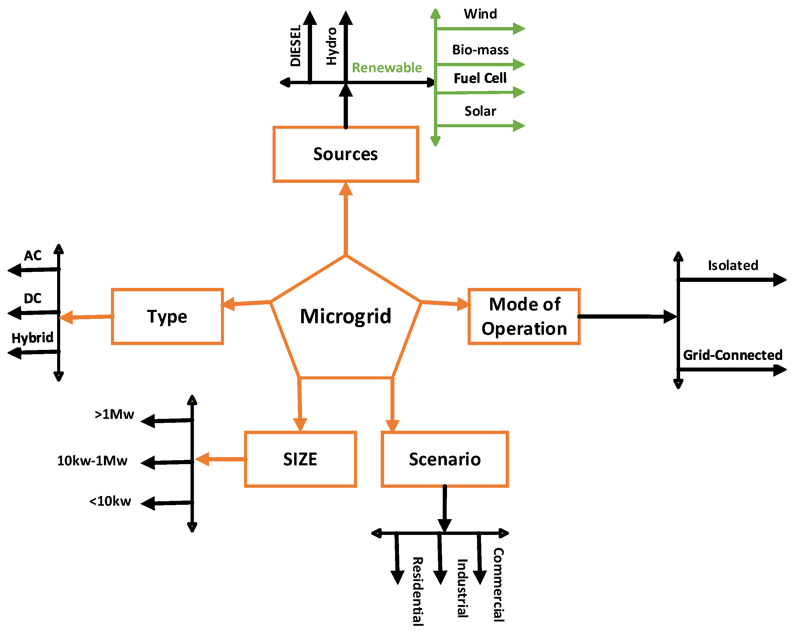
2. Different Architectures of Microgrids
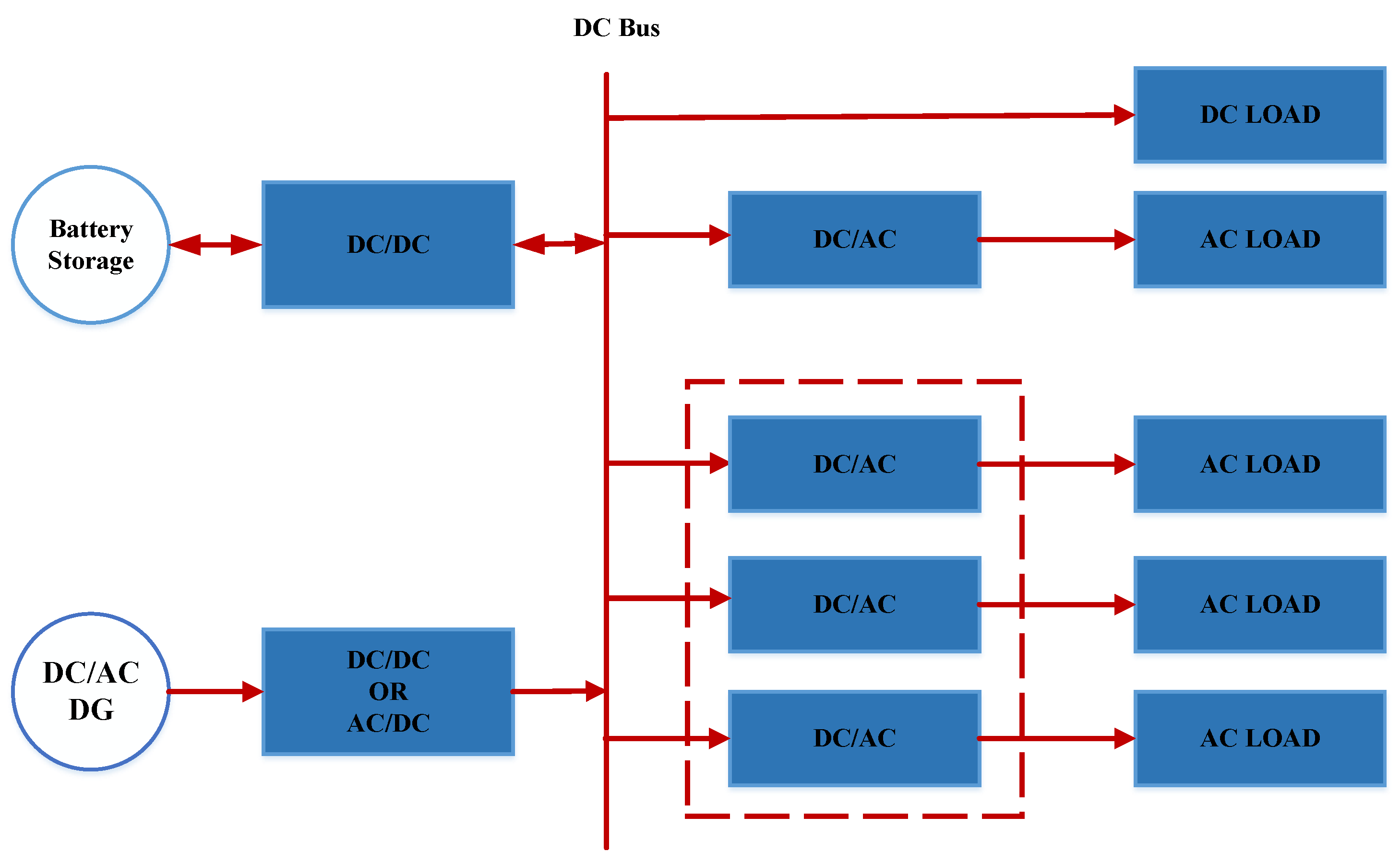
Normally, an MG is a combination of distributed energy resources, lines, different types of controllers, and loads. Different MGs, e.g., DC, AC, and AC/DC coupled MGs, have been discussed in [12]. Methods of interlinking converter control have been discussed for the hybrid AC/DC coupled architecture of MGs. Issues related to power flow, short-circuit, and stability improvement methods in MGs are discussed, which depend on different factors such as voltage (v) and frequency (f). An MG’s basic configuration and classification are shown in Figure 1. This explains the types of MGs, the modes in which MGs operate, and the different sources (hydro, diesel, wind, solar, etc.) used in MG distribution systems.

2.1. DC Microgrid

In the case of a DC MG, loads are directly connected to the DC node. All energy storage elements and DERs are attached to the DC bus with the help of the converter topology, shown in Figure 2. A DC subgrid can be unipolar or bipolar. A unipolar DC subgrid is a two-wire network with just one voltage level, whereas a bipolar DC subgrid is a three-wire network (positive, neutral, or negative) with two voltage levels. Energy storage elements are connected to the bus using a bidirectional converter, according to Figure 2.

2.2. AC Microgrid

In the AC MG structure, loads are directly connected to the AC bus. The connections between storage elements and DGs are explained in Figure 3. Energy storage elements are coupled with an AC bus with the help of a bidirectional converter interface. The voltage (V) and frequency (f) of the AC bus are maintained with the help of the grid in cases where it is grid-connected. In the case of islanded mode, an optimal control technique with supply and demand balance is used to maintain the AC bus voltage and frequency.

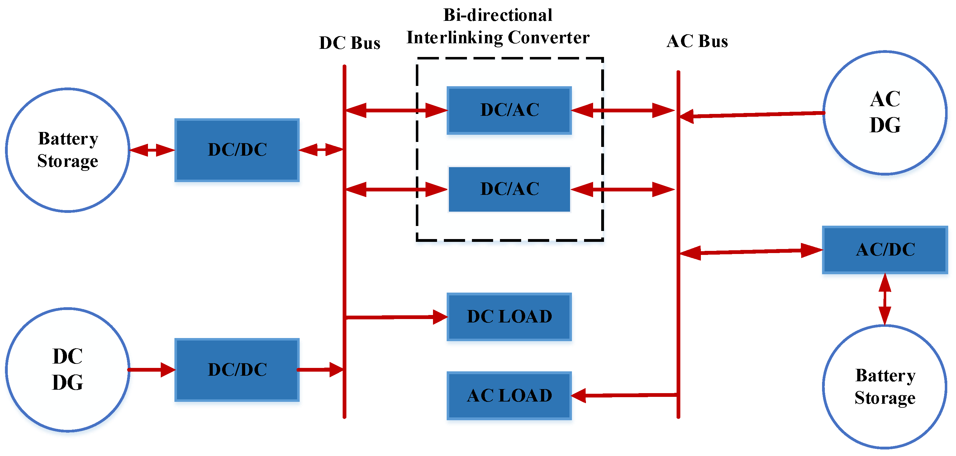
2.3. Hybrid AC/DC Coupled Microgrid

The architecture of a hybrid AC/DC MG is depicted in Figure 4; it includes both AC and DC sections of the MG system. A hybrid MG is a combination of DC and AC subgrids linked with interlinking converters (ILCs) that can operate in various modes. DGs with AC generation are connected to the AC bus. DC-generated DGs are connected to the DC bus. The ILC used in the system acts as a bidirectional converter that can transfer power from the DC to the AC bus and vice versa. It can reduce power conversion losses and lower costs by reducing the number of converters used in MG systems. Various energy conversion topologies for hybrid AC/DC microgrids, including both DC and AC systems, are discussed in [26,27]. These references offer a more comprehensive view of the different configurations used in energy conversion chains within hybrid microgrids.

3. Modeling of Hybrid AC/DC Microgrid

The basic architecture of an AC/DC hybrid MG is given in Figure 4, which consists of DGs, loads, distribution lines, and interlinking converters.

3.1. Modeling of AC DERs

Power electronic components can be divided into voltage-controlled voltage source inverters (VCVSIs) and current-controlled voltage source inverters (CCVSIs), which are typically used to integrate DGs into MGs. The frequency and voltages of DGs can be changed or adjusted by VCVSIs. By using VCVSIs, voltage and frequency can be separately controlled within given ranges, especially in the case of islanded mode. Consider a model in which frequency and voltage are used for the function of real and reactive power, as provided in (1) and (2), respectively, for a DG connected to an AC bus i. The droop control characteristics of DG are explained in Figure 5, which shows the P-V and Q-V relationship [28].
ω = ω 0 m p P i ,
V i = V 0 n q Q i ,
where i = 1, 2, 3, ⋯, N d g .
m p = ω m a x ω m i n P m a x , i ,
n q = | V | m a x | V | m i n Q m a x , i ,
Droop gains of DG units are represented in the form of active ( m p ) and reactive ( n q ) power gains. N d g is the number of DG units.
ω m a x and ω m i n are the highest and lowest allowable frequencies. V m a x and V m i n are the AC subgrid’s maximum and minimum allowable voltages.

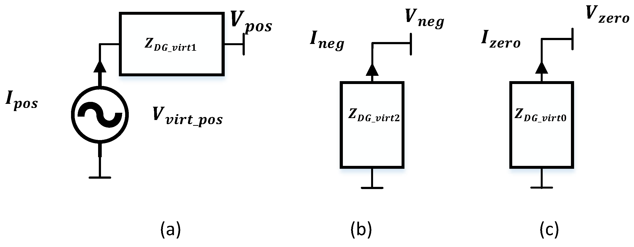
3.2. Modeling of IBDGs

An islanded mode of operation is considered a case of a virtual slack bus, including IBDGs. IBDG sequence components are given in Figure 6. According to Figure 6, modeling of the positive sequence component is achieved with the help of virtual impedance ( Z D G _ v i r t 1 ) and a voltage source ( V v i r t _ p o s ). With the assistance of the component’s virtual impedances, the modeling of zero-sequence and negative-sequence components was completed.
V p o s = V v i r t _ p o s I p o s . Z D G _ v i r t 1
V n e g = I n e g . Z D G _ v i r t 2
V z e r o = I z e r o . Z D G _ v i r t 0

3.3. Modeling of DC DERs

DC subgrid DGs are likewise subject to droop control. In contrast to an AC DG, a DC DG’s active power depends entirely on voltage, which is stated as
V i = V 0 m p , d c P i ,
The droop constant of DGs can be given as
m p , d c = V d c m a x V d c m i n P d c m a x ,
P d c m a x is the maximum power of a DC DG, V d c m a x is the maximum allowable voltage of the DC subgrid, and V d c m i n is the minimum allowable voltage of the DC subgrid [28].

3.4. AC Line Modeling

The modeling of an AC line considers both resistive and reactive parts; the reactance normally depends upon the frequency of the system.
Y ij ω = j i Z i j 1 ω i = j Z i j 1 ω i j
where Z i j ( ω ) = R i j + j X i j ( ω ) is the impedance of the line between the i th and j th bus [28].

3.5. DC Line Modeling

DC lines are entirely resistive in nature. G i j is conductance for any feeder linking to DC loads between the i th and j th nodes. The overall resistance of the branch is r i j , as follows:
G i j = ( r i j ) 1
The nodal supplied power of a DC bus i can be expressed as [29]
P d c , i = j ϵ N d c V d c , i . ( r i j ) 1 . V d c , j

3.6. AC Load Modeling

An AC load model can represent a composite load model; these kinds of models have dynamic as well as static features. The real and imaginary parts of power are expressed using a static load model as a function of the frequency and magnitude of the bus voltage. By allocating ZIP coefficients appropriately, AC loads are modeled using ZIP and the polynomial model as a combination of constant power, constant current, and constant impedance. For each load bus, the sum of the coefficients I p , Z p , and P p has to be 1, and the same is true for the coefficients of reactive power Z q , I q , and P q . The constants k p w and k q w have ranges of 0 to 2 and −2 to 0, respectively. These are constants that show the load’s dependency on frequency.
P L a c , i = P L a c , i 0 Z p , i V a c , i V a c , i 0 2 + I p , i V a c , i V a c , i 0 + P p , i [ 1 + k p w , i ω ω 0 ]
Q L a c , i = Q L a c , i 0 Z q , i V a c , i V a c , i 0 2 + I q , i V a c , i V a c , i 0 + P q , i [ 1 + k q w , i ω ω 0 ]
where P L a c , i and Q L a c , i are the real and reactive power consumed by the AC load at bus i, respectively. P L a c , i 0 and Q L a c , i 0 are the nominal real and reactive power of the AC subgrid, respectively. V a c , i 0 is the AC subgrid’s nominal voltage at the i th bus. Z p , I p , and P p are the ZIP coefficients of real power, representing constant values of impedance, current, and power in AC load models. Z q , I q , P q are the coefficients of reactive power of ZIP AC load models, which represent constant numeric values of impedance, current, and power according to the sequence. k q w and k p w are frequency-based constants of AC load reactive and real power, respectively [28].

3.7. DC Load Modeling

For DC loads, loads are similarly designed with constant values of resistance, constant current, or constant power [29]. The static voltage characteristic is also considered and given as
P L a c , i = P L a c , i 0 Z p , i V a c , i V a c , i 0 2 + I p , i V a c , i V a c , i 0 + P p , i
Q L a c , i = Q L a c , i 0 Z q , i V a c , i V a c , i 0 2 + I q , i V a c , i V a c , i 0 + P q , i

3.8. EV Loads

A polynomial or ZIP model of load can be used for EV loads, which consist of real and imaginary parts of apparent power, as given in (17) and (18). The mathematical expression obtained from the modeling of the battery and fast charging station is used to derive both formats of power for the EV load model.
P L = P L , 0 b + a V V 0 α ,
Q L = P L × t a n θ
where b is the power constant, a is the voltage-dependent power, α is the exponent of active power, and θ is the power factor of the connected load [30].

3.9. Interlinking Converter Modeling

Only real power can be exchanged between the AC-side subgrid and DC subgrid. DC real power is a function of voltage. The real power of the AC side depends on frequency. The normalized data can be used to compare the AC-side subgrid’s frequency and the DC-side subgrid’s voltage of the bus at various scales. The governing equations are given below:
ω ^ = ω 0.5 ω a c m a x + ω a c m i n 0.5 ω a c m a x ω a c m i n ,
V ^ D C = V 0.5 V D C m a x + V D C m i n 0.5 V D C m a x V D C m i n ,
Difference result of normalized voltage and current is Δ e = ω ^ V ^ D C .
When the normalized voltages of the DC-side buses are comparable to the AC subgrid’s normalized frequency, proportional sharing of power between both subgrids can be accomplished. AC frequencies and DC voltage limits are standardized to [−1, 1].
The process for converting power between AC and DC MGs is calculated based on the disparity between normalized voltage and frequency [29].
P I C d c = 1 k I C ω ^ V ^ D C
When the result is that Δ e > 0 , it is decided that AC-side MGs are more dominant than DC-side MGs, indicating that power flows from AC MGs to DC MGs, and conversely for Δ e < 0 .

4. Literature Review

In this research work, the main focus will be on the two most crucial challenges of hybrid AC/DC MGs, namely, (1) power flow analysis and (2) short-circuit/fault analysis. The literature on both problems is explained in a sequential flow to understand power flow and short-circuit analysis.

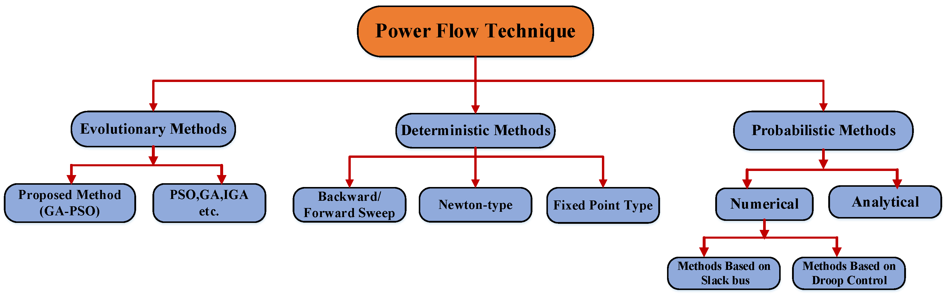
4.1. Power Flow Analysis

Power flow computations calculate voltages for certain load and source situations. Once all bus voltages are determined, slack node power, losses, and line power flow may be computed. We present different techniques for power flow analysis in this section. These techniques are mostly based on AC, DC, and hybrid AC/DC MGs. The power flow evaluation model, commonly referred to as the steady-state analysis framework, is used in the island situation of MGs. DGs may be linked to MGs through power electronic devices, and it is necessary to design an effective strategy for controlling electronic devices [3,4,5,31,32]. In [7], the author presents a review of power flow analysis using several techniques in the islanded mode of operation. The modeling of distinct operational modes of DGs is explained.
Building on the findings of the research in [28], the authors proposed algorithms related to the concept of the absence of a slack bus that solves the power flow of both AC and DC parts simultaneously. The results of this algorithm are compared with the study of already-existing algorithms of power flow that consider only one part, whether AC or DC subgrids. Furthermore, the author considers all of the distinguishing features of an islanded AC/DC MG, such as bidirectional power flow, droop-controlled DGs, and the absence of a slack bus. Finally, the technique is based on renowned N-R technology, which is efficient and straightforward to implement. When opposed to traditional networks, the power flow of islanded HMGs creates additional obstacles for the following reasons: (1) There is no such huge source to act as a slack bus, as is common in large networks. (2) Lines have a high ratio of R/X quantities. (3) The majority of the time, DGs operate in droop control mode with distinct voltage profiles. (4) Consideration should also be given to IC operation.
A power flow technique based on the Newton–Raphson (N-R) method is modeled for standalone MGs. Frequency variability is introduced to the composition in the model, and the slack bus is removed. Two types of buses are proposed for DG buses, which are PV and QV. However, their study does not take into account how line impedances and loads are affected by changes in frequency. In addition to that research, the authors have presented another variation of the usual N-R approach in [33].
A summarization of various types of power flow techniques is given in Figure 7. In this figure, evolutionary, deterministic, and probabilistic methods of power flow analysis are explained. These methods are used for the analysis of radial and meshed network power flow, and with the use of evolutionary methods, optimizing power flow can also be analyzed.
The modified Newton–Raphson (MNR) technique is offered to tackle load flow problems for autonomous MGs. The MNR approach considers frequency variability and its impact on additional system variables. Other load flow strategies, like BFS presented in [34,35,36,37,38,39,40,41], are tailored to the distribution network. However, only radial and weakly meshed distribution systems can use the BFS technique and its variations.
The authors developed an elaborate power flow approach for AC-islanded and grid-connected MGs based on a survey in [42,43]. The developed method is applied to balanced and unbalanced distribution systems. The methodology is based on an implicit Z b u s mechanism, which ensures rapid convergence and is independent of the R/X ratio. It should be noted that islanded MGs that use a master/slave strategy can also use the standard N-R methodology [44]. The authors of [45] separated the system into two zones based on the type of DGs used, namely, renewable and conventional. Islanded MGs cannot be divided into parts because they are not connected to a traditional grid.
In [46,47], the authors discussed important issues concerning the efficient management of DC and AC MGs. Variability in energy resources based on renewables, feeder placement, and cost-effective control approaches are also discussed. Power flow equations are nonlinear. Nonlinearity of equations causes complexity in optimization and control algorithms, which leads to non-convergence problems and high computation burdens. Therefore, the process of linearization of power flow equations is adopted in the literature to simplify the complexity of algorithms [48,49,50,51].
Power flow calculations are required during the design stage of HMGs to investigate a variety of topics such as IC and DG allocation and sizing, VAR planning, voltage stability, droop parameter regulation, contingency analysis, and so on [52]. Load flow can serve as a crucial tool in the real-time simulation of HMGs. It helps to reduce losses, optimize costs, and monitor voltage and frequency, as well as several other variables like the thermal limits of lines, operational DG limits, and IC limits during anticipated isolating.
In [53], an optimization model is used to show a new supervisory control strategy based on the model predictive control (MPC) mechanism. The purpose of this study is to determine how changing real and reactive power affects system frequency. Furthermore, variations in wind and PV output power are used to calculate variations in frequency. In [54], a universally reliable and computationally viable load flow approach is created by integrating numerous DG varieties and features of unbalanced droop-controlled MGs.
A summary of power flow analysis methods is given in Table 2 and Table 3. Table 2 and Table 3 consider criteria based on AC, DC, and AC/DC MGs, and radial, weakly meshed, islanded, and grid-connected modes of operation, and also include unbalanced systems and loads.
The MBFS algorithm for solving load flow was considered in [30,55,56]. Droop-controlled DGs have been placed into consideration for this strategy. Q V and P f modes of operation have been appropriately taken into consideration using DG droop criteria in conjunction with regular BFS strategies.
A robust modified decoupled NR method of power flow analysis was presented in [57] for solving abnormalities that occur in the islanded operational mode of MG. To share the load among numerous DGs for voltage and frequency management, the concept of a slack bus was offered. DGs are used in power flow analysis for distributing power. When all DGs are connected to an MG converter, a frequency droop controller is less efficient and less quick to react than an angle droop controller. It was shown that by changing the voltage’s amplitude and angle, the reactive and actual power that DGs share may be controlled in [58,59]. A lead–lag compensator is used for maintaining the stability of the system for power control in [60], using a high droop gain to improve load sharing. It is better to have a low gain at significant power output and a high gain at minimal output power to maintain stable situations during power sharing. An adaptive droop control is also included, which may modify the gain value in response to changes in load demand and supply provided by DGs [61].
In the literature, an N-R-based technology of power flow is considered, which relates to a modified current injection method (MCIM) [72]. PQ and PV bus representations for several electric vehicle (EV) loads have emerged. Based on National Household Travel Survey (NHTS) 2017 data, an EV load profile is created using a Monte Carlo simulation (MCS) while accounting for uncertainty in the driving patterns of plug-in hybrid electric cars (PHEVs). In [73], for unbalanced multiple-grounded four-wire distribution systems, an asymmetrical three-phase (with neutral) power flow problem based on rectification current injection methods was suggested. The proposed method was based on the formulation of the system’s admittance matrix.
In [74], the author suggested a model for regularly evaluating the flow of electricity into AC/DC mixed MGs under various conditions of production and use. The suggested application was created utilizing more than one input–output model composed of blocks, including basic representations of PV arrays, wind turbines (WTs), and battery arrays. A high degree of renewable penetration can cause stability issues and have an impact on system dynamics [76,77,78]. VSCs have emerged as a feasible solution to provide an interface with sources of energy that are differentiated by either varying frequency or DC, such as fuel cells, wind, and P-V, because of their many advantages and improved performance. A DC MG power flow is presented in [79], in which Newton–Raphson power flow based on a technique of current injection for a bipolar DC MG is created using network static models.
The authors of [80] demonstrated the power flow of a hybrid AC/DC MG utilizing a bus-sectionalized hybrid microgrid (BSHMG). The bus-sectionalized structure improves the reliability and flexibility of the hybrid MG without changing the design of the controller. The suggested control paradigm ensures seamless mode transition and continuous power output. In [81], the authors provided harmonic compensation using interfaces and ICs, in which harmonic control was handled by a converter with various power ratings, filter designs, and frequencies. Bidirectional converters in hybrid MG systems can provide reactive power and smart commutation by themselves and act as a voltage source.
A study was attempted in [82] to fully understand the impact of incorporating internal combustion engines (ICEs) and gas turbines into an AC/DC MG outfitted with PVs. A multi-objective genetic algorithm was used to optimize the system in terms of energy costs and efficiency in general. A basic discussion on an operational energy management system was carried out in Ref. [83]. The authors investigated three scenarios involving poor, perfect, and exact predictions. They evaluated their optimization approach on standalone and grid-connected systems despite large generation–load imbalances. MGs are often regarded as weak systems because they are prone to changes in loading circumstances and generation, which can result in subsequent instability problems and huge frequency deviations [84].
Researchers proved that raising the load on an AC MG shifts the dominant system poles to an unstable zone. As a result of power exchange through IC, the stability of a hybrid MG is dependent not only on the AC sub-system but also on the DC sub-system. The concept of a hybrid MG involves additional research into control operation, stability, and power sharing. The authors investigated and proposed an independent power-sharing operation based on droop control of HMGs, ICs, and DGs [85,86,87,88].
Papers related to the power flow of hybrid AC/DC MGs have presented studies on different techniques used in MG systems for AC as well as DC systems. The literature on load flow analysis for AC, DC, and hybrid AC/DC MGs is presented using various techniques in this section. The analysis of power flow techniques focused on the study of AC/DC HMGs. It is differentiated from others based on comparisons of types, modes of operation, and methods of MG systems.

4.2. Short-Circuit Analysis

A short-circuit analysis is a study performed to analyze the behavior of an electrical system during a fault condition. A fault occurs when an abnormal current path is created due to a breakdown or failure in insulation or other components of the system. A short-circuit analysis helps in understanding the magnitude and distribution of fault currents [17,89]. It also helps in finding the consequences of faults in components and devices used for the protection of the system.
  • A short circuit is defined as an electrical circuit in which the flow of current goes through an unintentional channel with very low impedance.
  • When a wire’s insulation cracks or another conducting substance is introduced, the charge might flow down an alternative route than it was intended to.
  • Current in a short-circuit analysis is limited only by the resistance of the rest of the circuit, and it can cause severe harm, such as fire and tiny explosions. The probability of fault occurrence due to short circuits may be in between a phase and ground, a phase and neutral, or two phases.
The basic short-circuit analysis strategies for MGs can be classified into two categories. (1) Symmetrical component-based approaches; (2) phase component-based approaches. Since symmetrical component-based approaches are assumed, there is equal mutual coupling between phases. Analysis of distribution system faults is explained in [90,91,92,93,94,95,96,97,98,99].
In [97], the author proposed a method for calculating short-circuit currents in a multi-IIDG distribution network using short-circuit features of three-phase IIDGs. These DGs are controlled by current under a grid fault. The sequence network’s mutual coupling for an unbalanced distribution system can be efficiently handled by the proposed method.
An IBDG was modeled in the format of a sequence component circuit to illustrate the operation of an inverter in a mode of current control for use in fault analysis. The main concept of the current-controlled inverter is based on the technique of dq-0 control. In this approach, phase factors of IBDG inverter current are first transformed into dq-0 sequence components, and a control mechanism for manipulating these converted dq-0 components is supplied. In [100], an experimental setup for fault analysis with a dq-0 control scheme for the inverter was implemented. However, these dq-0 component-based fault analysis methods were only carried out in time-domain simulation studies and were only tested on small-size distribution systems.
A conventional fault analysis method based on a system admittance matrix was proposed in [101], which includes inverter-interfaced distributed generators (IIDGs). In this scheme, it was assumed that the IIDG is operating in its voltage control mode during faults. The contribution of IIDGs during sub-transient and transient periods of the fault was also analyzed.
A [ Y b u s ] matrix-based method of short-circuit analysis and transformer models based on voltage and current equations are employed in [102]. In this method, for short-circuit calculations, the network’s description of the admittance matrix is constructed, and connection matrices for various transformer configurations are developed.
In the symmetrical component method, elements in the distribution system are presented by their circuits of positive-, negative-, and zero-sequence components. The fault analysis method using symmetrical components [103] uses an approach of modeling for 1-phase and 2-phase lines in the fault calculation. The three-phase impedance or admittance matrices that correspond to the distribution system’s components represent them in the phase domain. The method of triangular factorization of the [ Y b u s ] matrix to simulate different faults is presented in [104].
Models of co-generators (induction or synchronous generators) and three-phase transformers are also included in the test system. The method was applied to balanced, unbalanced, radial, and meshed-type distribution networks. A linear graph-based network modeling approach to forming the admittance matrix was proposed in [105]. A hybrid compensation-based short-circuit analysis method was proposed in [106]. In this method, two algorithms, namely, distribution power flow (DISFLO) and distribution short-circuit analysis (DISCA), were utilized. Two different lateral- and load-equivalent compensation-based approaches [107] were proposed for fault analysis of radial networks. For the investigation of short-circuit issues in this paper, the initial condition boundary matching (ICBM) method was utilized. Short-circuit analysis based on a technique that gives a relationship between two matrices [ BIBC ] and [ BCBV ] for radial and mesh distribution systems was presented in [108]. The correlation between the current of an injected bus and branch currents is presented by the [ BIBC ] matrix, whereas the relationship between the current of a particular branch and the voltages of each bus is shown by the [ BCBV ] matrix. The DG model used in this work is similar to the synchronous generator model used in the short-circuit study in [109]. The technique has undergone testing on several systems with various fault circumstances. The fault impedance effect on a faulted, unbalanced distribution system was described in [110]. This method is based on the bus impedance matrix [ Z b u s ] of the network, which includes the effect of fault impedances in calculations of fault analysis.
An algorithm of fault analysis is proposed in [111], in which the fault resistance effect for both weakly meshed as well as radial distribution networks is taken into account for fault current calculations. In this method, fault resistance is calculated, and then a modified bus impedance matrix is obtained, which includes the effect of the calculated fault resistance. A model-based fault diagnosis scheme was designed in [112]; it was capable of real-time detection of all types of faults in the distribution network. In this paper, a linear dynamical-fault-dependent state-space model of a single-machine infinite-bus (SMIB) power system was derived. This model is capable of capturing the dynamics of a complete system over a full-time scale and is therefore suitable for fault studies of any kind of fault. A multi-phase short-circuit analysis method based on the concept of a selected inversion algorithm called Sellnv was proposed in [113].
Various methods of short-circuiting have been presented in the literature for a three-phase, four-wire unbalanced distribution network. A current injection-based fault analysis method was presented in [114] for a multi-phase electrical distribution system. A Newton–Raphson-based technique was used in the proposed method. A transformer model based on a nodal admittance matrix has also been considered in short-circuit calculations. In [115], a method of short-circuit analysis for the computation of phase-to-earth currents for many faults in an unbalanced multi-wire radial distribution model was developed. The analysis of a multi-wire line model of an unbalanced system utilizing Kirchhoff’s rules and methods for solving linear equations forms the basis of the suggested approach. In [116], a method is utilized to calculate equivalent resistances for a formulation of a matrix of problems to calculate faults that result from short circuits according to the IEC 61660 standard.
A summary of the different techniques used for short-circuit analysis is presented in Table 4 and Table 5. Table 4 and Table 5 consider criteria based on AC, DC, and AC/DC MGs, and radial, weakly meshed, islanded, and grid-connected modes of operation, and also include unbalanced systems and loads of the microgrid network.
In the study in [126], the author proposed a new technique of fault analysis for AC MG systems, which takes into account fault current limiting, low-voltage ride-through, and inverter-interfaced distributed generation (IIDG) control strategies. The analysis was performed on fault models of PQ-controlled and V/f-controlled IIDG. The functioning state of V/F-IIDG was divided into a constant voltage and a constant current state following analysis of fault models. An enhanced model voltage equation based on current constraints was used in a constant current state. A grid-connected MG fault calculation approach was used in a constant-voltage state.
In [127], the author proposed a precise and efficient technique for analyzing short-circuit faults in weakly meshed unbalanced networks in distribution. To examine the impacts of various types of short-circuit failure on weakly meshed distribution networks, some practical and efficient formulas were developed in this study. In [128], the author presented a fault scenario on an MG with a solar panel, fuel cell, and wind turbine as the main components. The generated power from several sources was aggregated on a single DC bus and then transferred to a three-phase AC load using a three-phase inverter.
In [129,130], the authors analyzed an MG’s fault current disparities in two different operating situations and subsequently identified changes that must be made to the protection of relay and fault calculations in developing MGs. DER-based MG short-circuit analysis is performed in both islanded and grid-connected operational modes. High changes in fault currents based on operational mode are found after analysis of fault currents in two different modes. There could be significant post-fault disruptions in an islanded subgrid as a result of interactions between DERs and ICs. Therefore, if the fault clearing time goes over a certain threshold, the voltage of islanded subgrids cannot be stabilized. In the post-fault transient reaction of HMGs, numerous local controllers are engaged.
In the study of [131], a fresh approach improves on traditional short-circuit analysis techniques and gives a rough idea of fault current patterns. A typical feeder with simple loads and a PV-dominated distribution feeder have very different fault current profiles. The variance of the fault current is influenced by both the PV system’s fault current contribution and voltage-based protection strategies.
Ref. [132] gives an idea for identifying the system’s equivalent network with high-level sharing of resources based on inverter technology for studies of fault analysis. A nonlinear element (a voltage-dependent current source) is added to the conventional voltage source behind impedance representation in the proposed voltage-dependent network equivalents (VDNEs), which is a nonlinear equivalent. Because of a nonlinear relationship between the voltage present at the terminals of equivalent systems and the fault contribution made by VDNE, iterative computation of short-circuit currents is required.
A DC MG fault analysis is presented in [133], based on a precise representation of a DC MG’s parts. In a DC MG, steady power loads are incorporated as a conventional DC system loading profile, with batteries as energy storage devices and solar and wind as renewable energy sources. Due to practical considerations, all energy sources based on renewables are subject to maximum power point tracking (MPPT) regulations. In Ref. [134], for adding a full thermo-magnetic function to a hybrid Z-source circuit breaker (ZCB), it is suggested that fuses be used to make up for the Z-source circuit breaker’s functionality. In practical DC power systems, this technique would improve the dependability of short-circuit protection with ZCBs.
In [135], an MG system’s unbalanced behavior is presented, and this approach is used for fault analysis, which is based on a graph concept and a complicated MVA representation of short circuits. Instead of the conventional Z-bus methodology and inverse admittance matrix with the idea of the lower and upper triangular matrices, the incidence matrix K of the branch path and augmented incidence matrix K l , which is a newly constructed network, serve as the foundation for the suggested approach.
The study in Ref. [136] proposes a method for quickly calculating short-circuit currents in unbalanced distribution networks with DGs that interface with inverters (IIDG). It can estimate short-circuit current in unbalanced systems with multiple IIDGs by using symmetric components instead of computing the system bus impedance matrix.
In [137], the author analyzes changes in fault current between two different operating modes and ultimately concludes with improvements in fault calculations and relay protection analysis that are needed in developing the MGs. The utility system in grid-connected mode contributes the most fault current, with DERs making up no more than 20% of it. On the other hand, the sole sources of fault current in islanded mode are DERs, and the total fault current is much lower than it is in grid-linked mode.
A sequence component-based protection scheme was developed in [138], which considers protective zone density comparable to that of [139] but without any increase in protection robustness. This necessitates longer processing times and a more comprehensive communication infrastructure. The utilization of conventional distance protection for MGs and distribution networks was covered in [140].
In [141], a protective plan based on traveling waves was presented. The plan is based on polarity and time measurements made at both ends of the protected line immediately following the occurrence of a fault. The research effort, including the proposal of an impedance-based protection strategy with communication assistance, is presented in [142]. The suggested method relies on tracking impedance paths at various feeder relays to spot faults, and it makes use of directed elements to pinpoint their location.
In [143], a study based on a technique of transient modeling of a voltage source converter (VSC)-based DC MG is presented. Analysis of transient characteristics of VSCs in active power control mode and DC bus voltage control mode is followed by modeling of a defective DC MG, which comprises the VSC model and DC line model. Expressions of state variables in DC MGs are presented after SCC. The authors of [144] proposed a protection strategy for suppressing fault current in DC lines to improve the reliability of power in MGs.
Static modeling of MGs for fault analysis is presented in [145]. This uses the phasor simulation method and DGs with inverter interfaces for fault analysis of MGs in each operating mode. Instead of powers, constraints are applied to DG currents, and the established analysis approach additionally takes into account the impact of output filter capacitors. Ref. [146] determined the location of faults based upon impedance measurements for a distribution system using DGs at high frequencies. In this research, the author, regardless of the effects of the control loop, employed a DG model for fault location based on excessive frequency impedance.
The literature on short-circuit analysis of AC, DC, and hybrid AC/DC MGs is presented using various techniques in this section. The proposed analysis of short-circuit techniques is focused on a review of AC/DC MG’s techniques. It is differentiated from others based on a comparison of the analysis of AC and DC as well as the AC/DC short circuit.

5. Methodology

To investigate the effect of the power flow analysis and SCA, this study includes the various techniques of the load flow analysis of AC, DC, and hybrid AC/DC microgrids.

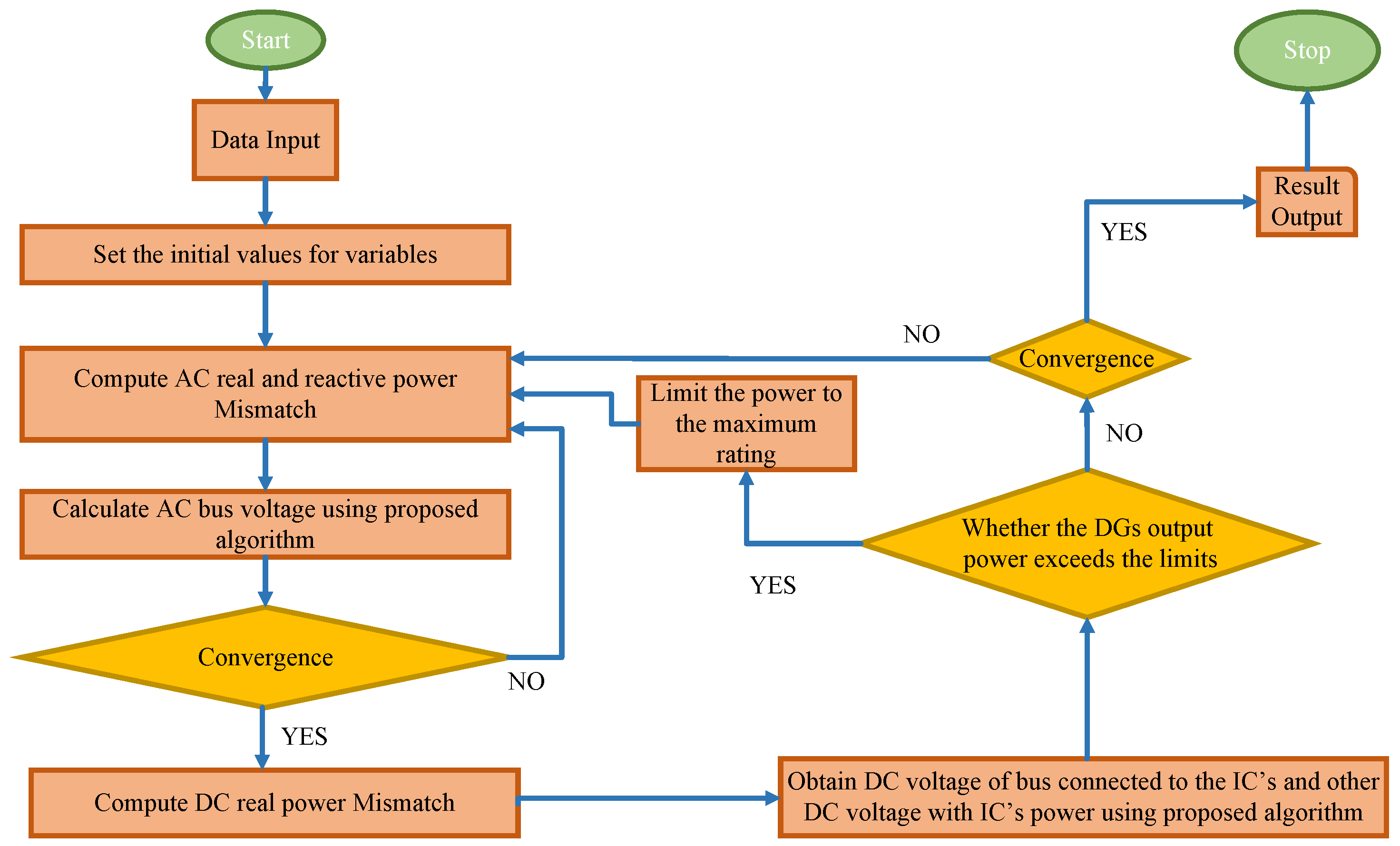
5.1. Power Flow Analysis

Various methods for the analysis of AC, DC, and hybrid AC/DC microgrid power flow are presented in Table 2 and Table 3. These methods are classified based on various categories like radial and meshed microgrid systems.
Power flow methods are classified based on the grid-tied modes and islanded mode of operation of a microgrid. Some of the methods are used to solve the power flow analysis of the unbalanced microgrid system. Methods that are used to solve the power flow of the islanded microgrid are based on modifications of the existing Jacobean matrix-based methods and based on modifications of the BFS methods due to the absence of the slack bus.
A general methodology of the power flow analysis of AC and DC microgrids is explained in the flowchart of a hybrid AC/DC microgrid. The fundamental steps of power flow analysis of AC/DC hybrid MGs are given in the flowchart, as shown in Figure 8.
This flowchart explains the basic procedure of AC load flow convergence and DC load flow convergence conditions. In this, the power flow through the bidirectional interlinking converter is also taken into consideration. An interlinking converter power is defined based on the AC subgrid’s frequency and the DC subgrid’s voltage.

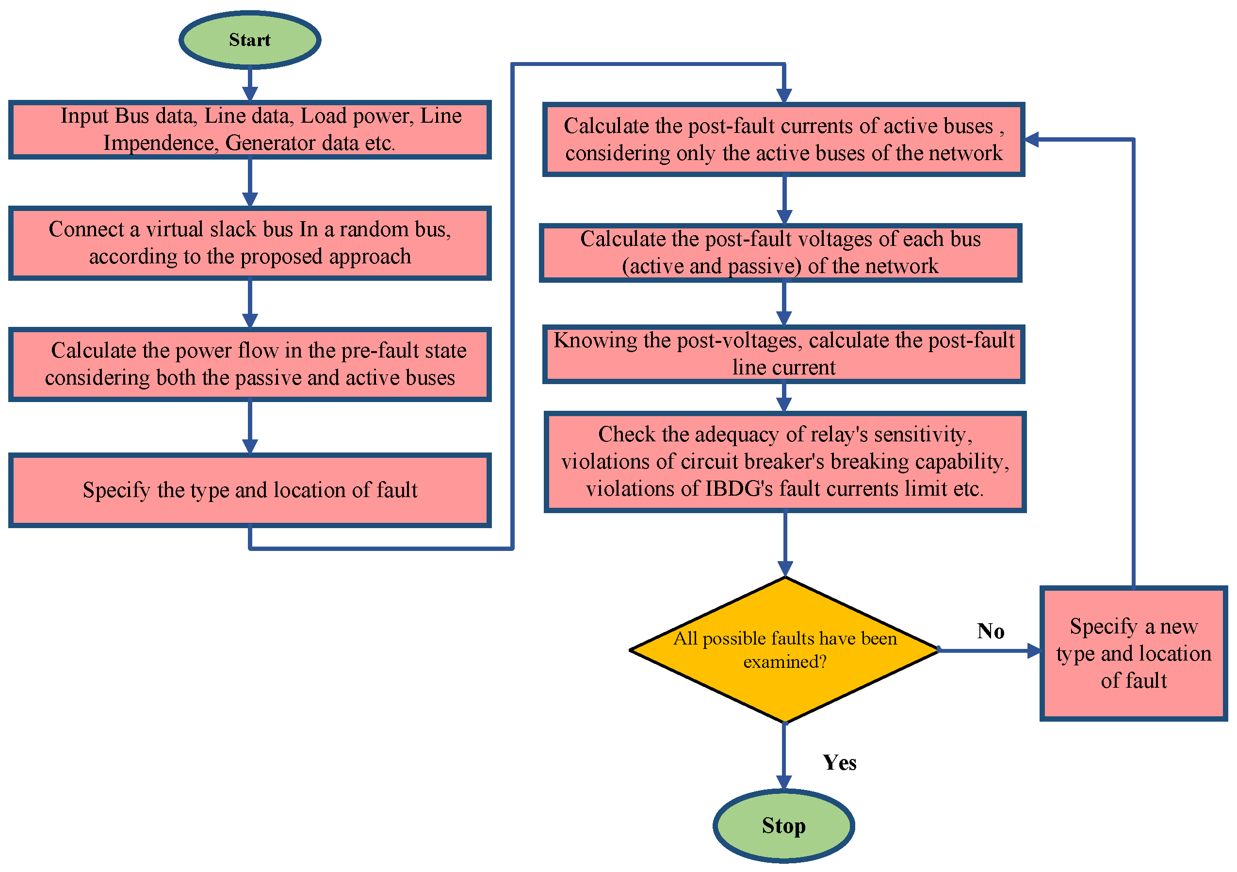
5.2. Short-Circuit Analysis

Various methods for the short-circuit analysis of AC and DC microgrids are discussed in Table 4 and Table 5. These methods are classified based on various categories like radial and weakly meshed microgrid distribution systems.
SCA methods are classified based on the grid-tied modes and islanded mode of operation of a microgrid. Some of the methods are used for fault analysis of unbalanced systems. Analysis of IBDG fault currents and voltages before and after faults is also discussed. The fundamental steps for short-circuit analysis of MGs are shown in Figure 9. The flowchart demonstrates the short-circuit evaluation approach, which follows the load flow investigation. Initially, the pre-fault load flow is determined to establish the system’s baseline. The fault location is then indicated within the network. After obtaining the type and location of fault, post-fault current and voltages are calculated.

6. Promising Areas of Scientific Research

This study identified many significant limitations in existing approaches for power flow and short-circuit evaluation in microgrids (MGs), especially considering the challenges that arise from renewable energy integration and fault scenarios. For the advancement in this field, more study is needed in various promising areas. Existing techniques for PFA and SCA should be improved to increase accuracy and computing efficiency. Future research could look into incorporating real-time data analysis, which makes possible more precise calculations of node voltages, currents, and electrical power flows during both normal and fault scenarios. Efficient evaluation of MG behavior requires precise simulation of components like DGs and ESSs, particularly during unexpected circumstances. Renewable energy’s unpredictable nature needs comprehensive models that can properly represent both steady-state and fault situations. MGs deal with a number of operational issues, including voltage variations, frequency deviations, and imbalances in power as a result of the inconsistent nature of renewable energy sources. Advanced control algorithms are needed to enable smooth functioning in both grid-tied and islanded modes. These algorithms should be capable of constantly balancing power distribution and adjusting to changing generation and load situations in real time to avoid stability difficulties. Existing short-circuit evaluation methods for both DC- and AC-islanded MG networks frequently lack the flexibility required to handle the unpredictability caused by renewable sources. Enhancing fault analysis techniques, particularly under dynamic and changing settings, can increase MGs’ robustness. Future research should focus on developing intelligent algorithms that provide rapid and precise fault analysis in order to ensure the system’s service continuity. Addressing these issues in future research will help to make MG systems more reliable, efficient, and capable of managing the difficulties introduced due to renewable energy sources and fault conditions.

7. Conclusions

This paper provides a comprehensive review of the approaches for power flow and short-circuit analysis in AC, DC, and hybrid AC/DC microgrids (HMGs). The power flow between AC and DC subgrids is controlled through bidirectional interlinking converters which ensure stable operation in both grid-connected and islanded modes of microgrids. The bidirectional converters control the bus voltage for DC-side operation and the frequency of AC MG operation. The modeling of AC, DC, and hybrid AC/DC MG components has been investigated, with a focus on voltage and frequency control, especially in islanded operation, where frequency variations are considered as unknown variables. The short-circuit analysis process of a hybrid AC/DC MG also considered the modeling of different components, including IBDGs. Different methods of analysis of faults occurring due to short circuits are explained in the literature. A comparative analysis of both short-circuit and power flow analysis has been presented, and a comprehensive review of AC, DC, and hybrid AC/DC MGs has been proposed. These findings have an important impact on the design and control of hybrid AC/DC microgrids since they provide knowledge about how to improve reliability and effectiveness. The study provides the groundwork for future research into optimizing power flow and fault management procedures in hybrid AC/DC MGs, which are critical for their broad adoption in modern, sustainable energy systems.

Author Contributions

Conceptualization, G.M., V.M. and A.T.A.; Formal analysis, G.M., V.M., A.M., V.P.S., A.T.A. and I.A.H.; Funding acquisition, I.A.H.; Investigation, A.T.A. and I.A.H.; Methodology, G.M., V.M., A.M., V.P.S., A.T.A. and I.A.H.; Resources, G.M., V.M., A.M., V.P.S. and I.A.H.; Software, G.M., V.M., A.M. and V.P.S.; Validation, A.M., V.P.S. and I.A.H.; Visualization, A.T.A.; Writing—original draft, G.M., V.M., A.M., V.P.S. and A.T.A.; Writing—review & editing, G.M., V.M., A.M., V.P.S., A.T.A. and I.A.H. All authors have read and agreed to the published version of the manuscript.

Funding

This research was funded by the Norwegian University of Science and Technology, Norway.

Data Availability Statement

The authors declare no associated data in the manuscript.

Acknowledgments

The authors would like to acknowledge the support of the Norwegian University of Science and Technology for paying the Article Processing Charges (APC) of this publication. This research is supported by the Automated Systems and Soft Computing Lab (ASSCL), Prince Sultan University, Riyadh, Saudi Arabia. The authors would like to thank Prince Sultan University, Riyadh, Saudi Arabia for their support.

Conflicts of Interest

The authors declare that the research was conducted in the absence of any commercial or financial relationships that could be construed as a potential conflict of interest.

References

  1. Sheykhi, N.; Salami, A.; Guerrero, J.M.; Agundis-Tinajero, G.D.; Faghihi, T. A comprehensive review on telecommunication challenges of microgrids secondary control. Int. J. Electr. Power Energy Syst. 2022, 140, 108081. [Google Scholar] [CrossRef]
  2. Zolfaghari, M.; Gharehpetian, G.B.; Shafie-khah, M.; Catalão, J.P. Comprehensive review on the strategies for controlling the interconnection of AC and DC microgrids. Int. J. Electr. Power Energy Syst. 2022, 136, 107742. [Google Scholar] [CrossRef]
  3. Green, T.C.; Prodanović, M. Control of inverter-based micro-grids. Electr. Power Syst. Res. 2007, 77, 1204–1213. [Google Scholar] [CrossRef]
  4. Gao, F.; Iravani, M.R. A control strategy for a distributed generation unit in grid-connected and autonomous modes of operation. IEEE Trans. Power Deliv. 2008, 23, 850–859. [Google Scholar]
  5. Vandoorn, T.L.; Meersman, B.; De Kooning, J.D.; Vandevelde, L. Analogy between conventional grid control and islanded microgrid control based on a global DC-link voltage droop. IEEE Trans. Power Deliv. 2012, 27, 1405–1414. [Google Scholar] [CrossRef]
  6. Yoldaş, Y.; Önen, A.; Muyeen, S.; Vasilakos, A.V.; Alan, I. Enhancing smart grid with microgrids: Challenges and opportunities. Renew. Sustain. Energy Rev. 2017, 72, 205–214. [Google Scholar] [CrossRef]
  7. Moradi, M.H.; Foroutan, V.B.; Abedini, M. Power flow analysis in islanded Micro-Grids via modeling different operational modes of DGs: A review and a new approach. Renew. Sustain. Energy Rev. 2017, 69, 248–262. [Google Scholar] [CrossRef]
  8. Hirsch, A.; Parag, Y.; Guerrero, J. Microgrids: A review of technologies, key drivers, and outstanding issues. Renew. Sustain. Energy Rev. 2018, 90, 402–411. [Google Scholar] [CrossRef]
  9. Bolgouras, V.; Ntantogian, C.; Panaousis, E.; Xenakis, C. Distributed key management in microgrids. IEEE Trans. Ind. Inform. 2019, 16, 2125–2133. [Google Scholar] [CrossRef]
  10. Cagnano, A.; De Tuglie, E.; Mancarella, P. Microgrids: Overview and guidelines for practical implementations and operation. Appl. Energy 2020, 258, 114039. [Google Scholar] [CrossRef]
  11. Azeem, O.; Ali, M.; Abbas, G.; Uzair, M.; Qahmash, A.; Algarni, A.; Hussain, M.R. A comprehensive review on integration challenges, optimization techniques and control strategies of hybrid AC/DC Microgrid. Appl. Sci. 2021, 11, 6242. [Google Scholar] [CrossRef]
  12. Jain, D.; Saxena, D. Comprehensive review on control schemes and stability investigation of hybrid AC-DC microgrid. Electr. Power Syst. Res. 2023, 218, 109182. [Google Scholar] [CrossRef]
  13. Pompodakis, E.E.; Kryonidis, G.C.; Demoulias, C.; Alexiadis, M.C. A generic power flow algorithm for unbalanced islanded hybrid AC/DC microgrids. IEEE Trans. Power Syst. 2020, 36, 1107–1120. [Google Scholar] [CrossRef]
  14. Surendra, K.; Das, B.; Pant, V. Static state estimation of islanded AC/DC Hybrid microgrids. Int. J. Electr. Power Energy Syst. 2024, 155, 109612. [Google Scholar] [CrossRef]
  15. Tinajero, G.D.A.; Nasir, M.; Vasquez, J.C.; Guerrero, J.M. Comprehensive power flow modelling of hierarchically controlled AC/DC hybrid islanded microgrids. Int. J. Electr. Power Energy Syst. 2021, 127, 106629. [Google Scholar] [CrossRef]
  16. Kamh, M.Z.; Iravani, R. Unbalanced model and power-flow analysis of microgrids and active distribution systems. IEEE Trans. Power Deliv. 2010, 25, 2851–2858. [Google Scholar] [CrossRef]
  17. Mathur, A.; Pant, V.; Das, B. Unsymmetrical short-circuit analysis for distribution system considering loads. Int. J. Electr. Power Energy Syst. 2015, 70, 27–38. [Google Scholar] [CrossRef]
  18. Meena, G.; Singh, V.P.; Sundariyal, N.; Mathur, A. Component Model of AC Microgrid for Short-Circuit Analysis. In Proceedings of the 2024 1st International Conference on Innovative Sustainable Technologies for Energy, Mechatronics, and Smart Systems (ISTEMS), Dehradun, India, 26–27 April 2024; pp. 1–6. [Google Scholar]
  19. Strezoski, L.; Prica, M.; Loparo, K.A. Generalized Δ-circuit concept for integration of distributed generators in online short-circuit calculations. IEEE Trans. Power Syst. 2016, 32, 3237–3245. [Google Scholar] [CrossRef]
  20. Pompodakis, E.E.; Strezoski, L.; Simic, N.; Paspatis, A.G.; Alexiadis, M.C.; Tsikalakis, A.G.; Katsigiannis, Y.A.; Karapidakis, E.S. Short-circuit calculation of droop-controlled islanded AC microgrids with virtual impedance current limiters. Electr. Power Syst. Res. 2023, 218, 109184. [Google Scholar] [CrossRef]
  21. Jabr, R.A.; Džafić, I. A Fortescue approach for real-time short circuit computation in multiphase distribution networks. IEEE Trans. Power Syst. 2014, 30, 3276–3285. [Google Scholar] [CrossRef]
  22. Abdelmalek, S.; Azar, A.T.; Dib, D. A novel actuator fault-tolerant control strategy of DFIG-based wind turbines using Takagi-Sugeno multiple models. Int. J. Control. Autom. Syst. 2018, 16, 1415–1424. [Google Scholar] [CrossRef]
  23. Varshney, T.; Waghmare, A.; Meena, V.; Singh, V.; Ramprabhakar, J.; Khan, B.; Singh, S. FOPDT model and CHR method based control of flywheel energy storage integrated microgrid. Sci. Rep. 2024, 14, 21550. [Google Scholar] [CrossRef] [PubMed]
  24. Pradhan, R.; Jena, P. An innovative fault direction estimation technique for AC microgrid. Electr. Power Syst. Res. 2023, 215, 108997. [Google Scholar] [CrossRef]
  25. Daraz, A.; Malik, S.A.; Azar, A.T.; Aslam, S.; Alkhalifah, T.; Alturise, F. Optimized fractional order integral-tilt derivative controller for frequency regulation of interconnected diverse renewable energy resources. IEEE Access 2022, 10, 43514–43527. [Google Scholar] [CrossRef]
  26. Mariam, L.; Basu, M.; Conlon, M.F. A review of existing microgrid architectures. J. Eng. 2013, 2013, 937614. [Google Scholar] [CrossRef]
  27. Tehrani, K.; Weber, M.; Rasoanarivo, I. Hybrid Power System Optimization for Microgrids. In Proceedings of the 2021 23rd European Conference on Power Electronics and Applications (EPE’21 ECCE Europe), Virtual, 6–10 September 2021; pp. 1–9. [Google Scholar]
  28. Aprilia, E.; Meng, K.; Al Hosani, M.; Zeineldin, H.H.; Dong, Z.Y. Unified power flow algorithm for standalone AC/DC hybrid microgrids. IEEE Trans. Smart Grid 2017, 10, 639–649. [Google Scholar] [CrossRef]
  29. Liu, Y.; Li, Z.; Fan, M. A Newton–Raphson-based sequential power flow algorithm for hybrid AC/DC microgrids. IEEE Trans. Ind. Appl. 2021, 58, 843–854. [Google Scholar] [CrossRef]
  30. Kongjeen, Y.; Bhumkittipich, K. Modeling of electric vehicle loads for power flow analysis based on PSAT. In Proceedings of the 2016 13th International Conference on Electrical Engineering/Electronics, Computer, Telecommunications and Information Technology (ECTI-CON), Chiang Mai, Thailand, 28 June–1 July 2016; pp. 1–6. [Google Scholar]
  31. Chaudhary, R.; Singh, V.; Mathur, A.; Meena, V.; Murari, K. Truncation-based Approximation of Autonomous Microgrid. In Proceedings of the 2024 IEEE Kansas Power and Energy Conference (KPEC), Manhattan, KS, USA, 25–26 April 2024; pp. 1–5. [Google Scholar]
  32. Mathur, A.; Kumari, R.; Meena, V.; Singh, V.; Azar, A.T.; Hameed, I.A. Data-driven optimization for microgrid control under distributed energy resource variability. Sci. Rep. 2024, 14, 10806. [Google Scholar] [CrossRef]
  33. Mumtaz, F.; Syed, M.; Al Hosani, M.; Zeineldin, H. A novel approach to solve power flow for islanded microgrids using modified Newton Raphson with droop control of DG. IEEE Trans. Sustain. Energy 2015, 7, 493–503. [Google Scholar] [CrossRef]
  34. Shirmohammadi, D.; Hong, H.W.; Semlyen, A.; Luo, G. A compensation-based power flow method for weakly meshed distribution and transmission networks. IEEE Trans. Power Syst. 1988, 3, 753–762. [Google Scholar] [CrossRef]
  35. Kumar, Y.; Meena, V.; Mathur, A.; Singh, V. Fault Detection and Localization in Distribution System using Sparse Matrix Reconstruction. In Proceedings of the 2023 International Conference on Computer, Electronics & Electrical Engineering & Their Applications (IC2E3), Srinagar Garhwal, India, 8–9 June 2023; pp. 1–6. [Google Scholar]
  36. Luo, G.X.; Semlyen, A. Efficient load flow for large weakly meshed networks. IEEE Trans. Power Syst. 1990, 5, 1309–1316. [Google Scholar] [CrossRef]
  37. Daraz, A.; Malik, S.A.; Waseem, A.; Azar, A.T.; Haq, I.U.; Ullah, Z.; Aslam, S. Automatic generation control of multi-source interconnected power system using FOI-TD controller. Energies 2021, 14, 5867. [Google Scholar] [CrossRef]
  38. Chang, G.; Chu, S.; Wang, H. An improved backward/forward sweep load flow algorithm for radial distribution systems. IEEE Trans. Power Syst. 2007, 22, 882–884. [Google Scholar] [CrossRef]
  39. Krishna, P.; Khan, B. Rank-sum-weight method based systematic determination of weights for controller tuning for automatic generation control. IEEE Access 2022, 10, 68161–68174. [Google Scholar] [CrossRef]
  40. Pilla, R.; Azar, A.T.; Gorripotu, T.S. Impact of flexible AC transmission system devices on automatic generation control with a metaheuristic based fuzzy PID controller. Energies 2019, 12, 4193. [Google Scholar] [CrossRef]
  41. Augugliaro, A.; Dusonchet, L.; Favuzza, S.; Ippolito, M.G.; Sanseverino, E.R. A backward sweep method for power flow solution in distribution networks. Int. J. Electr. Power Energy Syst. 2010, 32, 271–280. [Google Scholar] [CrossRef]
  42. Pompodakis, E.E.; Kryonidis, G.C.; Alexiadis, M.C. A comprehensive load flow approach for grid-connected and islanded AC microgrids. IEEE Trans. Power Syst. 2019, 35, 1143–1155. [Google Scholar] [CrossRef]
  43. Meena, G.; Saini, D.; Meena, V.; Mathur, A.; Singh, V. A Modified Implicit Z-Bus Method for an Unbalanced Hybrid AC-DC Microgrids. In Proceedings of the 2023 IEEE IAS Global Conference on Renewable Energy and Hydrogen Technologies (GlobConHT), Male, Maldives, 11–12 March 2023; pp. 1–6. [Google Scholar]
  44. Nikkhajoei, H.; Iravani, R. Steady-state model and power flow analysis of electronically-coupled distributed resource units. IEEE Trans. Power Deliv. 2006, 22, 721–728. [Google Scholar] [CrossRef]
  45. Ashfaq, S.; Zhang, D.; Zhang, C.; Dong, Z.Y. Load flow investigations for regionalized islanded microgrid considering frequency regulation with high renewable penetration. Electr. Power Syst. Res. 2023, 214, 108904. [Google Scholar] [CrossRef]
  46. Eajal, A.; Abdelwahed, M.A.; El-Saadany, E.; Ponnambalam, K. A unified approach to the power flow analysis of AC/DC hybrid microgrids. IEEE Trans. Sustain. Energy 2016, 7, 1145–1158. [Google Scholar] [CrossRef]
  47. Hameed, F.; Al Hosani, M.; Zeineldin, H.H. A modified backward/forward sweep load flow method for islanded radial microgrids. IEEE Trans. Smart Grid 2017, 10, 910–918. [Google Scholar] [CrossRef]
  48. Rao, G.K.; Jena, P. A Novel Fault Identification and Localization Scheme for Bipolar DC Microgrid. IEEE Trans. Ind. Inform. 2023, 19, 11752–11764. [Google Scholar] [CrossRef]
  49. Mishra, A.; Jena, P. Application of Blockchain Technology for Microgrid Restoration. IEEE Trans. Power Deliv. 2022, 38, 1810–1825. [Google Scholar] [CrossRef]
  50. Meena, V.; Yadav, U.; Mathur, A.; Singh, V.; Guerrero, J.M.; Khan, B. Location and size selection using hybrid Jaya-Luus-Jaakola algorithm for decentralized generations in distribution system considering demand-side management. IET Renew. Power Gener. 2023, 17, 1535–1544. [Google Scholar] [CrossRef]
  51. Naveen, P.; Jena, P. A robust protection scheme for multimicrogrids using fault current limiter. IEEE Trans. Ind. Appl. 2022, 58, 5763–5775. [Google Scholar] [CrossRef]
  52. Gangwar, T.; Padhy, N.P.; Jena, P. Storage Allocation in Active Distribution Networks Considering Life Cycle and Uncertainty. IEEE Trans. Ind. Inform. 2022, 19, 339–350. [Google Scholar] [CrossRef]
  53. Mansoorhoseini, P.; Mozafari, B.; Mohammadi, S. Islanded AC/DC microgrids supervisory control: A novel stochastic optimization approach. Electr. Power Syst. Res. 2022, 209, 108028. [Google Scholar] [CrossRef]
  54. Allam, M.A.; Hamad, A.A.; Kazerani, M. A generic modeling and power-flow analysis approach for isochronous and droop-controlled microgrids. IEEE Trans. Power Syst. 2018, 33, 5657–5670. [Google Scholar] [CrossRef]
  55. Nassar, M.E.; Hamad, A.A.; Salama, M.; El-Saadany, E.F. A novel load flow algorithm for islanded AC/DC hybrid microgrids. IEEE Trans. Smart Grid 2017, 10, 1553–1566. [Google Scholar] [CrossRef]
  56. Amritha, M.; Savier, J. Load Flow Analysis of Islanded Droop Regulated Microgrids. In Proceedings of the 2020 International Conference on Power, Instrumentation, Control and Computing (PICC), Thrissur, India, 17–19 December 2020; pp. 1–6. [Google Scholar]
  57. Lone, A.H.; Gupta, N. A Novel Modified Decoupled Newton-Raphson Load Flow Method with Distributed Slack Bus for Islanded Microgrids Considering Frequency Variations. Electr. Power Components Syst. 2023, 52, 678–696. [Google Scholar] [CrossRef]
  58. Goyal, M.; Ghosh, A.; Zare, F. Power sharing control with frequency droop in a hybrid microgrid. In Proceedings of the 2013 IEEE Power & Energy Society General Meeting, Vancouver, BC, Canada, 21–25 July 2013; pp. 1–5. [Google Scholar]
  59. Majumder, R.; Ghosh, A.; Ledwich, G.; Zare, F. Operation and control of hybrid microgrid with angle droop controller. In Proceedings of the TENCON 2010–2010 IEEE Region 10 Conference, Fukuoka, Japan, 21–24 November 2010; pp. 509–515. [Google Scholar]
  60. Majumder, R.; Chaudhuri, B.; Ghosh, A.; Majumder, R.; Ledwich, G.; Zare, F. Improvement of stability and load sharing in an autonomous microgrid using supplementary droop control loop. IEEE Trans. Power Syst. 2009, 25, 796–808. [Google Scholar] [CrossRef]
  61. Farhadi, M.; Mohammed, O. Adaptive energy management in redundant hybrid DC microgrid for pulse load mitigation. IEEE Trans. Smart Grid 2014, 6, 54–62. [Google Scholar] [CrossRef]
  62. Wang, H.; Yan, Z.; Xu, X.; He, K. Probabilistic power flow analysis of microgrid with renewable energy. Int. J. Electr. Power Energy Syst. 2020, 114, 105393. [Google Scholar] [CrossRef]
  63. Kongjeen, Y.; Bhumkittipich, K.; Mithulananthan, N.; Amiri, I.; Yupapin, P. A modified backward and forward sweep method for microgrid load flow analysis under different electric vehicle load mathematical models. Electr. Power Syst. Res. 2019, 168, 46–54. [Google Scholar] [CrossRef]
  64. Abdelaziz, M.M.A.; Farag, H.E.; El-Saadany, E.F.; Mohamed, Y.A.R.I. A novel and generalized three-phase power flow algorithm for islanded microgrids using a newton trust region method. IEEE Trans. Power Syst. 2012, 28, 190–201. [Google Scholar] [CrossRef]
  65. Li, C.; Chaudhary, S.K.; Savaghebi, M.; Vasquez, J.C.; Guerrero, J.M. Power flow analysis for low-voltage AC and DC microgrids considering droop control and virtual impedance. IEEE Trans. Smart Grid 2016, 8, 2754–2764. [Google Scholar] [CrossRef]
  66. Allam, M.A.; Hamad, A.A.; Kazerani, M.; El-Saadany, E.F. A steady-state analysis tool for unbalanced islanded hybrid AC/DC microgrids. Electr. Power Syst. Res. 2017, 152, 71–83. [Google Scholar] [CrossRef]
  67. Xiao, Y.; Ren, C.; Han, X.; Wang, P. A generalized and mode-adaptive approach to the power flow analysis of the isolated hybrid AC/DC microgrids. Energies 2019, 12, 2253. [Google Scholar] [CrossRef]
  68. Wang, R.; Sun, Q.; Ma, D.; Zhang, X. The equivalent impedance characteristic analysis of the AC microgrid and its decoupled power flow calculation. Int. Trans. Electr. Energy Syst. 2019, 29, e2820. [Google Scholar] [CrossRef]
  69. Wang, R.; Sun, Q.; Liu, X.; Ma, D. Power flow calculation based on local controller impedance features for the AC microgrid with distributed generations. IET Energy Syst. Integr. 2019, 1, 202–209. [Google Scholar] [CrossRef]
  70. Morgan, M.Y.; Shaaban, M.F.; Sindi, H.F.; Zeineldin, H.H. A holomorphic embedding power flow algorithm for islanded hybrid AC/DC microgrids. IEEE Trans. Smart Grid 2022, 13, 1813–1825. [Google Scholar] [CrossRef]
  71. Allam, M.A.; Hamad, A.A.; Kazerani, M. A sequence-component-based power-flow analysis for unbalanced droop-controlled hybrid AC/DC microgrids. IEEE Trans. Sustain. Energy 2018, 10, 1248–1261. [Google Scholar] [CrossRef]
  72. Jha, B.K.; Kumar, A.; Dheer, D.K.; Singh, D.; Misra, R.K. A modified current injection load flow method under different load model of EV for distribution system. Int. Trans. Electr. Energy Syst. 2020, 30, e12284. [Google Scholar] [CrossRef]
  73. Sunderland, K.; Coppo, M.; Conlon, M.; Turri, R. A correction current injection method for power flow analysis of unbalanced multiple-grounded 4-wire distribution networks. Electr. Power Syst. Res. 2016, 132, 30–38. [Google Scholar] [CrossRef]
  74. López-Santos, O.; Salas-Castaño, M.C.; Salazar-Dantonio, D.F. Continuous Simulation of the Power Flow in AC–DC Hybrid Microgrids Using Simplified Modelling. Computation 2022, 10, 52. [Google Scholar] [CrossRef]
  75. Srivastava, A.K.; Kumar, A.A.; Schulz, N.N. Impact of distributed generations with energy storage devices on the electric grid. IEEE Syst. J. 2012, 6, 110–117. [Google Scholar] [CrossRef]
  76. Chen, Y.; Hesse, R.; Turschner, D.; Beck, H.P. Improving the grid power quality using virtual synchronous machines. In Proceedings of the 2011 International Conference on Power Engineering, Energy and Electrical Drives, Malaga, Spain, 11–13 May 2011; pp. 1–6. [Google Scholar]
  77. Liu, J.; Miura, Y.; Ise, T. Comparison of dynamic characteristics between virtual synchronous generator and droop control in inverter-based distributed generators. IEEE Trans. Power Electron. 2015, 31, 3600–3611. [Google Scholar] [CrossRef]
  78. Chen, Y.; Hesse, R.; Turschner, D.; Beck, H.P. Comparison of methods for implementing virtual synchronous machine on inverters. In Proceedings of the International Conference on Renewable Energies and Power Quality, Santiago de Compostela, Spain, 28–30 March 2012; Volume 1, pp. 1–15. [Google Scholar]
  79. Lee, J.O.; Kim, Y.S.; Moon, S.I. Current injection power flow analysis and optimal generation dispatch for bipolar DC microgrids. IEEE Trans. Smart Grid 2020, 12, 1918–1928. [Google Scholar] [CrossRef]
  80. Li, J.; Cai, H.; Yang, P.; Wei, W. A bus-sectionalized hybrid ac/dc microgrid: Concept, control paradigm, and implementation. Energies 2021, 14, 3508. [Google Scholar] [CrossRef]
  81. Li, C.; Chaudhary, S.K.; Vasquez, J.C.; Guerrero, J.M. Power flow analysis for droop controlled LV hybrid AC-DC microgrids with virtual impedance. In Proceedings of the 2014 IEEE PES General Meeting| Conference & Exposition, National Harbor, MD, USA, 27–31 July 2014; pp. 1–4. [Google Scholar]
  82. Das, B.K.; Al-Abdeli, Y.M.; Kothapalli, G. Effect of load following strategies, hardware, and thermal load distribution on stand-alone hybrid CCHP systems. Appl. Energy 2018, 220, 735–753. [Google Scholar] [CrossRef]
  83. Luna, A.C.; Meng, L.; Diaz, N.L.; Graells, M.; Vasquez, J.C.; Guerrero, J.M. Online energy management systems for microgrids: Experimental validation and assessment framework. IEEE Trans. Power Electron. 2017, 33, 2201–2215. [Google Scholar] [CrossRef]
  84. Guan, M.; Pan, W.; Zhang, J.; Hao, Q.; Cheng, J.; Zheng, X. Synchronous generator emulation control strategy for voltage source converter (VSC) stations. IEEE Trans. Power Syst. 2015, 30, 3093–3101. [Google Scholar] [CrossRef]
  85. Wang, P.; Jin, C.; Zhu, D.; Tang, Y.; Loh, P.C.; Choo, F.H. Distributed control for autonomous operation of a three-port AC/DC/DS hybrid microgrid. IEEE Trans. Ind. Electron. 2014, 62, 1279–1290. [Google Scholar] [CrossRef]
  86. Radwan, A.A.A.; Mohamed, Y.A.R.I. Networked control and power management of AC/DC hybrid microgrids. IEEE Syst. J. 2014, 11, 1662–1673. [Google Scholar] [CrossRef]
  87. Mohamed, Y.A.R.I.; El-Saadany, E.F. Adaptive decentralized droop controller to preserve power sharing stability of paralleled inverters in distributed generation microgrids. IEEE Trans. Power Electron. 2008, 23, 2806–2816. [Google Scholar] [CrossRef]
  88. Bhavana, G.; Anand, R.; Ramprabhakar, J.; Meena, V.; Jadoun, V.K.; Benedetto, F. Applications of blockchain technology in peer-to-peer energy markets and green hydrogen supply chains: A topical review. Sci. Rep. 2024, 14, 21954. [Google Scholar] [CrossRef]
  89. Mathur, A.; Das, B.; Pant, V. Fault analysis of unbalanced radial and meshed distribution system with inverter based distributed generation (IBDG). Int. J. Electr. Power Energy Syst. 2017, 85, 164–177. [Google Scholar] [CrossRef]
  90. Plet, C.A.; Graovac, M.; Green, T.C.; Iravani, R. Fault response of grid-connected inverter dominated networks. In Proceedings of the IEEE PES General Meeting, Minneapolis, MN, USA, 25–29 July 2010; pp. 1–8. [Google Scholar]
  91. Plet, C.A.; Green, T.C. Fault response of inverter interfaced distributed generators in grid-connected applications. Electr. Power Syst. Res. 2014, 106, 21–28. [Google Scholar] [CrossRef]
  92. Baskaran, J.; Naghapushanam, M.; Ganapathy, M.; Meena, P.; Meena, V.; Azar, A.T.; Hameed, I.A. Cost-effective high-gain dc-dc converter for elevator drives using photovoltaic power and switched reluctance motors. Front. Energy Res. 2024, 12, 1400651. [Google Scholar] [CrossRef]
  93. Rodriguez, P.; Timbus, A.V.; Teodorescu, R.; Liserre, M.; Blaabjerg, F. Flexible active power control of distributed power generation systems during grid faults. IEEE Trans. Ind. Electron. 2007, 54, 2583–2592. [Google Scholar] [CrossRef]
  94. Camacho, A.; Castilla, M.; Miret, J.; Vasquez, J.C.; Alarcon-Gallo, E. Flexible voltage support control for three-phase distributed generation inverters under grid fault. IEEE Trans. Ind. Electron. 2012, 60, 1429–1441. [Google Scholar] [CrossRef]
  95. Miret, J.; Castilla, M.; Camacho, A.; de Vicuña, L.G.; Matas, J. Control scheme for photovoltaic three-phase inverters to minimize peak currents during unbalanced grid-voltage sags. IEEE Trans. Power Electron. 2012, 27, 4262–4271. [Google Scholar] [CrossRef]
  96. DebBarman, S.; Namrata, K.; Kumar, N.; Meena, V. Optimising power distribution systems: Solar-powered capacitors and cost reduction through meta-heuristic methods. Int. J. Intell. Eng. Inform. 2024, 12, 188–212. [Google Scholar] [CrossRef]
  97. Wang, Q.; Zhou, N.; Ye, L. Fault analysis for distribution networks with current-controlled three-phase inverter-interfaced distributed generators. IEEE Trans. Power Deliv. 2015, 30, 1532–1542. [Google Scholar] [CrossRef]
  98. Nimpitiwan, N.; Heydt, G.T.; Ayyanar, R.; Suryanarayanan, S. Fault current contribution from synchronous machine and inverter based distributed generators. IEEE Trans. Power Deliv. 2006, 22, 634–641. [Google Scholar] [CrossRef]
  99. Ebrahimi, E.; Sanjari, M.J.; Gharehpetian, G.B. Control of three-phase inverter-based DG system during fault condition without changing protection coordination. Int. J. Electr. Power Energy Syst. 2014, 63, 814–823. [Google Scholar] [CrossRef]
  100. Darwish, A.; Abdel-Khalik, A.; Elserougi, A.; Ahmed, S.; Massoud, A. Fault current contribution scenarios for grid-connected voltage source inverter-based distributed generation with an LCL filter. Electr. Power Syst. Res. 2013, 104, 93–103. [Google Scholar] [CrossRef]
  101. Baran, M.E.; El-Markaby, I. Fault analysis on distribution feeders with distributed generators. IEEE Trans. Power Syst. 2005, 20, 1757–1764. [Google Scholar] [CrossRef]
  102. Tan, A.; Liu, W.H.; Shirmohammadi, D. Transformer and load modeling in short circuit analysis for distribution systems. IEEE Trans. Power Syst. 1997, 12, 1315–1322. [Google Scholar] [CrossRef]
  103. Abdel-Akher, M.; Nor, K.M. Fault analysis of multiphase distribution systems using symmetrical components. IEEE Trans. Power Deliv. 2010, 25, 2931–2939. [Google Scholar] [CrossRef]
  104. Chen, T.H.; Chen, M.S.; Lee, W.J.; Kotas, P.; Van Olinda, P. Distribution system short circuit analysis-A rigid approach. IEEE Trans. Power Syst. 1992, 7, 444–450. [Google Scholar] [CrossRef]
  105. Halpin, S.; Grigsby, L.; Gross, C.; Nelms, R. An improved fault analysis algorithm for unbalanced multi-phase power distribution systems. IEEE Trans. Power Deliv. 1994, 9, 1332–1338. [Google Scholar] [CrossRef]
  106. Zhang, X.; Soudi, F.; Shirmohammadi, D.; Cheng, C.S. A distribution short circuit analysis approach using hybrid compensation method. IEEE Trans. Power Syst. 1995, 10, 2053–2059. [Google Scholar] [CrossRef]
  107. Mao, Y.; Miu, K. Radial distribution system short circuit analysis with lateral and load equivalencing: Solution algorithms and numerical results. In Proceedings of the 2000 Power Engineering Society Summer Meeting (Cat. No. 00CH37134), Seattle, WA, USA, 16–20 July 2000; Volume 1, pp. 449–453. [Google Scholar]
  108. Teng, J.H. Fast short circuit analysis method for unbalanced distribution systems. In Proceedings of the 2003 IEEE Power Engineering Society General Meeting (IEEE Cat. No. 03CH37491), Toronto, ON, Canada, 13–17 July 2003; Volume 1, pp. 240–245. [Google Scholar]
  109. Chen, T.H.; Chen, M.S.; Inoue, T.; Kotas, P.; Chebli, E.A. Three-phase cogenerator and transformer models for distribution system analysis. IEEE Trans. Power Deliv. 1991, 6, 1671–1681. [Google Scholar] [CrossRef]
  110. Paz, M.C.R.; Ferraz, R.G.; Bretas, A.S.; Leborgne, R.C. System unbalance and fault impedance effect on faulted distribution networks. Comput. Math. Appl. 2010, 60, 1105–1114. [Google Scholar]
  111. Filomena, A.D.; Resener, M.; Salim, R.H.; Bretas, A.S. Distribution systems fault analysis considering fault resistance estimation. Int. J. Electr. Power Energy Syst. 2011, 33, 1326–1335. [Google Scholar] [CrossRef]
  112. Saha, S.; Aldeen, M.; Tan, C.P. Unsymmetrical fault diagnosis in transmission/distribution networks. Int. J. Electr. Power Energy Syst. 2013, 45, 252–263. [Google Scholar] [CrossRef]
  113. Lacroix, J.S.; Kocar, I.; Belletête, M. Accelerated computation of multiphase short circuit summary for unbalanced distribution systems using the concept of selected inversion. IEEE Trans. Power Syst. 2012, 28, 1515–1522. [Google Scholar] [CrossRef]
  114. Penido, D.R.R.; de Araujo, L.R.; de Carvalho Filho, M. An enhanced tool for fault analysis in multiphase electrical systems. Int. J. Electr. Power Energy Syst. 2016, 75, 215–225. [Google Scholar] [CrossRef]
  115. Klucznik, J. Earth wires currents calculation by tableau analysis. Electr. Power Syst. Res. 2017, 151, 329–337. [Google Scholar] [CrossRef]
  116. Favuzza, S.; Mitolo, M.; Moradi, S.; Musca, R.; Zizzo, G. A General Methodology for Short-circuit Calculations in Hybrid AC/DC Microgrids. IEEE Trans. Ind. Appl. 2023, 59, 2742–2749. [Google Scholar] [CrossRef]
  117. Kim, I. Short-circuit analysis models for unbalanced inverter-based distributed generation sources and loads. IEEE Trans. Power Syst. 2019, 34, 3515–3526. [Google Scholar] [CrossRef]
  118. Ou, T.C. A novel unsymmetrical faults analysis for microgrid distribution systems. Int. J. Electr. Power Energy Syst. 2012, 43, 1017–1024. [Google Scholar] [CrossRef]
  119. Yu, M.; Wang, Y.; Zhang, L.; Zhang, Z. DC short circuit fault analysis and protection of ring type DC microgrid. In Proceedings of the 2016 IEEE 8th International Power Electronics and Motion Control Conference (IPEMC-ECCE Asia), Hefei, China, 22–26 May 2016; pp. 1694–1700. [Google Scholar]
  120. Lu, X.; Wang, J.; Guerrero, J.M.; Zhao, D. Virtual-impedance-based fault current limiters for inverter dominated AC microgrids. IEEE Trans. Smart Grid 2016, 9, 1599–1612. [Google Scholar] [CrossRef]
  121. Zhao, M.; Zheng, X. Waveform characteristic analysis and recognition of short-circuit fault in grid-connected AC microgrid. In Proceedings of the 2019 4th International Conference on Intelligent Green Building and Smart Grid (IGBSG), Yichang, China, 6–9 September 2019; pp. 732–735. [Google Scholar]
  122. Eisapour-Moarref, A.; Kalantar, M.; Esmaili, M. Control strategy resilient to unbalanced faults for interlinking converters in hybrid microgrids. Int. J. Electr. Power Energy Syst. 2020, 119, 105927. [Google Scholar] [CrossRef]
  123. Azizpour, A.; Radmehr, M.; Firouzi, M.; Gharehpetian, G. Single AC/DC fault current limiter for both side of hybrid AC/DC microgrid. Int. J. Electron. 2022, 110, 1337–1354. [Google Scholar] [CrossRef]
  124. Xiao, F.; Xia, Y.; Zhang, K.; Zhang, Z.; Yin, X. Short-circuit calculation method for unbalanced distribution networks with doubly fed induction generators. Electr. Power Syst. Res. 2022, 210, 108108. [Google Scholar] [CrossRef]
  125. Miret, J.; Castilla, M.; Velasco, M.; Guzmán, R.; de Vicuña, L.G. Maximum current injection method for grid-forming inverters in an islanded microgrid subject to short circuits. IET Power Electron. 2023, 16, 1028–1042. [Google Scholar] [CrossRef]
  126. Wang, Z.; Mu, L.; Xu, Y.; Zhang, F.; Zhu, J. The fault analysis method of islanded microgrid based on the U/f and PQ control strategy. Int. Trans. Electr. Energy Syst. 2021, 31, e12919. [Google Scholar] [CrossRef]
  127. Teng, J.H. Unsymmetrical short-circuit fault analysis for weakly meshed distribution systems. IEEE Trans. Power Syst. 2009, 25, 96–105. [Google Scholar] [CrossRef]
  128. Bayindir, R.; Irmak, E.; Issi, F.; Guler, N. Short-circuit fault analysis on microgrid. In Proceedings of the 2015 International Conference on Renewable Energy Research and Applications (ICRERA), Palermo, Italy, 22–25 November 2015; pp. 1248–1252. [Google Scholar]
  129. Simic, N.; Strezoski, L.; Dumnic, B. Short-circuit analysis of DER-based microgrids in connected and islanded modes of operation. Energies 2021, 14, 6372. [Google Scholar] [CrossRef]
  130. Seyedi, Y.; Mahseredjian, J.; Karimi, H. Impact of fault impedance and duration on transient response of hybrid AC/DC microgrid. Electr. Power Syst. Res. 2021, 197, 107298. [Google Scholar] [CrossRef]
  131. Hooshyar, H.; Baran, M.E. Fault analysis on distribution feeders with high penetration of PV systems. IEEE Trans. Power Syst. 2012, 28, 2890–2896. [Google Scholar] [CrossRef]
  132. Furlaneto, R.; Kocar, I.; Grilo-Pavani, A.; Karaagac, U.; Haddadi, A.; Farantatos, E. Short circuit network equivalents of systems with inverter-based resources. Electr. Power Syst. Res. 2021, 199, 107314. [Google Scholar] [CrossRef]
  133. Nahas, E.W.; Abd el Ghany, H.A.; Mansour, D.E.A.; Eissa, M. Extensive analysis of fault response and extracting fault features for DC microgrids. Alex. Eng. J. 2021, 60, 2405–2420. [Google Scholar] [CrossRef]
  134. Fu, R.; Montross, K.C. A New Method of Coordinating ZCBs and Fuses for a Reliable Short-Circuit Protection in DC Power Networks. IEEE Access 2022, 10, 63270–63279. [Google Scholar] [CrossRef]
  135. Hsieh, T.Y.; Chen, T.H.; Yang, N.C.; Lee, W.J. Efficient network fault analysis method for unbalanced microgrid systems. Int. J. Electr. Power Energy Syst. 2018, 103, 89–101. [Google Scholar] [CrossRef]
  136. He, J.; Li, Z.; Li, W.; Zou, J.; Li, X.; Wu, F. Fast short-circuit current calculation of unbalanced distribution networks with inverter-interfaced distributed generators. Int. J. Electr. Power Energy Syst. 2023, 146, 108728. [Google Scholar] [CrossRef]
  137. Luka, S.; Simic, N.; Dumnic, B. Fault current study of microgrids in grid-connected and islanded modes of operation. In Proceedings of the 12th Mediterranean Conference on Power Generation, Transmission, Distribution and Energy Conversion (MEDPOWER 2020), IET, Paphos, Cyprus, 9–12 November 2020; Volume 2020, pp. 372–377. [Google Scholar]
  138. Casagrande, E.; Woon, W.L.; Zeineldin, H.H.; Svetinovic, D. A differential sequence component protection scheme for microgrids with inverter-based distributed generators. IEEE Trans. Smart Grid 2013, 5, 29–37. [Google Scholar] [CrossRef]
  139. Sortomme, E.; Venkata, S.; Mitr, J. Microgrid Protection Using Communication-Assisted Digital Relays. IEEE Trans. Power Deliv. 2010, 25, 2789–2796. [Google Scholar] [CrossRef]
  140. Rajaei, N.; Ahmed, M.H.; Salama, M.M.; Varma, R.K. Fault current management using inverter-based distributed generators in smart grids. IEEE Trans. Smart Grid 2014, 5, 2183–2193. [Google Scholar] [CrossRef]
  141. Li, X.; Dyśko, A.; Burt, G.M. Traveling wave-based protection scheme for inverter-dominated microgrid using mathematical morphology. IEEE Trans. Smart Grid 2014, 5, 2211–2218. [Google Scholar] [CrossRef]
  142. Elkhatib, M.E.; Ellis, A. Communication-assisted impedance-based microgrid protection scheme. In Proceedings of the 2017 IEEE Power & Energy Society General Meeting, Chicago, IL, USA, 16–20 July 2017; pp. 1–5. [Google Scholar]
  143. Nian, H.; Kong, L. Transient modeling and analysis of VSC based DC microgrid during short circuit fault. IEEE Access 2019, 7, 170604–170614. [Google Scholar] [CrossRef]
  144. Zha, X.; Ning, H.; Lai, X.; Huang, Y.; Liu, F. Suppression strategy for short-circuit current in loop-type DC microgrid. In Proceedings of the 2014 IEEE Energy Conversion Congress and Exposition (ECCE), Pittsburgh, PA, USA, 14–18 September 2014; pp. 758–764. [Google Scholar]
  145. Dağ, B.; Boynueğri, A.R.; Ateş, Y.; Karakaş, A.; Nadar, A.; Uzunoğlu, M. Static modeling of microgrids for load flow and fault analysis. IEEE Trans. Power Syst. 2016, 32, 1990–2000. [Google Scholar] [CrossRef]
  146. Jia, K.; Bi, T.; Ren, Z.; Thomas, D.W.; Sumner, M. High frequency impedance based fault location in distribution system with DGs. IEEE Trans. Smart Grid 2016, 9, 807–816. [Google Scholar] [CrossRef]
Figure 1. Configurations and classification of MGs.
Mca 29 00108 g001
Figure 2. Architecture of DC MG.
Mca 29 00108 g002
Figure 3. Architecture of AC MG.
Mca 29 00108 g003
Figure 4. Architecture of AC/DC hybrid MG.
Mca 29 00108 g004
Figure 5. Droop control characteristics.
Mca 29 00108 g005
Figure 6. (a) Positive-sequence, (b) negative-sequence, and (c) zero-sequence components of IBDG.
Mca 29 00108 g006
Figure 7. Summarization of power flow techniques.
Mca 29 00108 g007
Figure 8. Flowchart for power flow analysis of hybrid AC/DC MG.
Mca 29 00108 g008
Figure 9. Flowchart for short-circuit analysis of AC MG.
Mca 29 00108 g009
Table 1. Comparison of existing review papers.
Ref.YearArchitectureILCPFASCA
ACDCAC/DC
[3]2007××××
[4]2008××××
[5]2012××××
[6]2017×××
[7]2017×××
[8]2018××××
[9]2020×××××
[10]2020××××
[11]2021××××
[12]2023×××
This review2024
Note: ILC—interlinking converter; PFA—power flow analysis; SCA—short-circuit analysis.
Table 2. Summary of power flow analysis methods for MGs.
Ref.TechniqueArchitectureR/WM/
Is/GC
Unbalanced
ACDCAC/DC
[28]Newton–Raphson (N-R)××Is
[29]N-R××Is
[30]Power system analysis toolbox (PSAT)××R×
[33]Modified Newton–Raphson (MNR)××Is
[34]Compensation-based method××R/WM
[36]Tree-based load flow××WM×
[38]Improved backward–forward sweep (IBFS)××R
[41]Backward–forward sweep (BFS)××R/WM
[42]Implicit Z-Bus××Is/GC
[43]Modified implicit Z-Bus××Is/GC
[44]Conventional PF using DR××Is/GC×
[45]Clustering-based method××R/Is
[46]Newton trust region (NTR)××R/Is
[47]Modified backward–forward sweep××R/Is×
[48]Fault identification××R×
[49]Blockchain technology××R×
[51]Fault current limiter××R×
[52]Mixed-integer linear programming××R/Is×
[53]Model predictive control××Is
[54]Sequence component-based PF××GC
[55]Modified branch-based approach××Is×
[56]BFS××R/Is
[57]Modified Newton–Raphson××Is
[58]Controlling and power sharing××Is/GC×
[59]Angle droop control××GC×
[60]Droop-based power sharing××Is×
[61]Adaptive energy calculation××GC×
[62]Global sensitivity analysis (GSA)××Is/GC
[63]MBFS PF××R
[64]Newton trust region (NTR)××Is
[65]Virtual impedance-based power flow×GC×
[66]NTR××Is
[67]Unified power flow model××Is
[68]Impedance based××GC×
Note: R—radial network; WM—weakly meshed network; Is—islanded MG network; GC—grid-connected MG network.
Table 3. Summary of power flow analysis methods for MGs.
Ref.TechniqueArchitectureR/WM/
Is/GC
Unbalanced
ACDCAC/DC
[69]Local controller impedance features××GC×
[70]Holomorphic embedding××Is
[71]Sequence component-based PF××Is
[72]Modified current injection method (MCIM)××R
[73]Current injection method (CIM)××R
[74]Multiple-input multiple-output model××Is/GC
[75]Hybrid optimization model××R×
[76]Virtual synchronous machine (VISMA)××R×
[77]VSM-based control××Is/GC×
[78]Virtual synchronous machine (VSM)××Is×
[79]Current injection method (CIM)××GC
[80]Bus-sectionalized method××Is/GC×
[81]Droop control and virtual impedance××GC×
[82]Genetic algorithm××R×
[83]Adaptable energy management××Is/GC×
[84]VSC control××R×
[85]Power control××R×
[86]Power management××Is×
[87]Droop based××GC×
Note: R—radial network; WM—weakly meshed network; Is—islanded MG network; GC—grid-connected MG network.
Table 4. Literature survey on short-circuit analysis.
Ref.TechniqueArchitectureR/WM/
Is/GC
Unbalanced
ACDCAC/DC
[20]Delta-circuit and VICL (SCC)××Is
[21]Fortescue approach××R
[90]Inverter-based fault response××GC×
[91]IIDG fault response××GC×
[93]Power control during fault××R/GC×
[94]Voltage source control (VSC)××R/GC
[95]Inverter control××R/GC
[97]Fault analysis××GC/DS
[98]Fault calculation Z-bus matrix××R/GC
[99]IBDG controlling××R/GC
[100]VSC-based fault current controlling××R/GC
[101]Distribution system fault analysis××R/GC×
[102]Short-circuit analysis××R/GC×
[103]Symmetrical component based××R
[104]Phase-based system××R
[105]Improved fault analysis algorithm××R
[106]Hybrid compensation××R
[107]Fault analysis××R
[117]IBDG SCC××R
[109]Transformer model based××R
[110]Symmetrical component/ phase component××R
[111]Fault resistance estimation××R
[112]Unsymmetrical fault analysis××R×
[113]Fault analysis××R
[118]Hybrid compensation method××Is/GC
[119]Current differential protection××GC×
[120]Virtual impedance based××Is×
[121]Wavelet energy spectrum××GC×
[122]Fault analysis of interlinking converters××GC
[123]Fault current limiter××GC×
[124]DFIG-based SCC××R
[125]MCIM××Is
[114]CIM××R
Note: R—radial network; WM—weakly meshed network; Is—islanded MG network; GC—grid-connected MG network.
Table 5. Literature survey on short-circuit analysis.
Ref.TechniqueArchitectureR/WM/
Is/GC
Unbalanced
ACDCAC/DC
[115]Fault current calculation××R
[116]SCC calculation IEC 61660××R×
[126]V/F and PQ control××Is
[127]BIBC××WM
[128]SCC of MG××GC
[129]DER based××Is/GC
[130]Fault impedance based××R×
[131]Time-varying fault analysis××R×
[132]Voltage-dependent network equivalents (VDNEs)××R×
[133]Fault analysis××GC×
[134]ZCBs and fuse based××GC×
[135]Augmented matrix based××GC
[136]Simple generalized minimal residual (SGMRES)××R
[137]Fault current calculation××Is/GC
[138]IBDG fault current calculation××Is/GC
[139]Communication-assisted digital relays××GC
[140]IBDG fault current calculation××R
[141]Mathematical morphology××R
[142]Impedance based××GC×
[143]VSC based××GC×
[144]SC current suppression××GC×
[145]Static modeling approach××GC
[146]Impedance based××R
Note: R—radial network; WM—weakly meshed network; Is—islanded MG network; GC—grid-connected MG network.
Disclaimer/Publisher’s Note: The statements, opinions and data contained in all publications are solely those of the individual author(s) and contributor(s) and not of MDPI and/or the editor(s). MDPI and/or the editor(s) disclaim responsibility for any injury to people or property resulting from any ideas, methods, instructions or products referred to in the content.

