Abstract
Through the development of solid phase microextraction (SPME) technologies, thin film solid phase microextraction (TF-SPME) has been repeatedly validated as a novel sampling device well suited for various applications. These applications, encompassing a wide range of sampling methods such as onsite, in vivo and routine analysis, benefit greatly from the convenience and sensitivity TF-SPME offers. TF-SPME, having both an increased extraction phase volume and surface area to volume ratio compared to conventional microextraction techniques, allows high extraction rates and enhanced capacity, making it a convenient and ideal sampling tool for ultra-trace level analysis. This review provides a comprehensive discussion on the development of TF-SPME and the applications it has provided thus far. Emphasis is given on its application to thermal desorption, with method development and optimization for this desorption method discussed in detail. Moreover, a detailed outlook on the current progress of TF-SPME development and its future is also discussed with emphasis on its applications to environmental, food and fragrance analysis.
1. Introduction
As the need for more sensitive and greener alternatives in analytical chemistry continues to grow [1,2,3,4,5], it is necessary for the further development of robust sample preparation technologies to meet these modern demands. Sample preparation, being the first step in any analytical procedure, is far-reaching since any and all steps in the workflow are consequently affected by the sampling and extraction method used. The sampling and clean-up of compounds before introduction into an instrument plays a critical role in the achieved sensitivity and quantitative capabilities of the method. Consequently, novel extraction techniques must be developed to enhance analytical performance, while meeting the newfound call for greener sample preparation methods. Microextraction, being characterized by a small amount of extraction phase compared to the volume of the sample [6], affords the opportunity of substantially reducing the amount of organic solvent used while still achieving similar or better results compared to more traditional extraction techniques such as solid phase extraction (SPE) [7,8] and liquid–liquid extraction (LLE) [9]. The volume of the extraction phase, being inconsequential to the overall volume of the sample [6], allows rapid non-exhaustive extraction, in some cases non-depletive, that can easily be quantitated using a variety of calibration methods [10]. Moreover, analytes from the sample matrix are extracted in their “free-form” (non-bound or free-concentration), giving the opportunity for the analysis of bio-available analytes in various matrices. Among existing microextraction techniques, solid phase microextraction (SPME) is the most widely adopted as it allows solvent-less extraction that can be easily automated and adapted for in vivo and onsite applications [11]. The conventional configuration of SPME consists of an extraction phase coated on a solid, fiber-like support composed of fused silica, stainless steel or flexible metal alloys; this geometry allows ease of use and automated extraction and analysis [11]. As a sample preparation method, the use of SPME enables sampling and pre-concentration to be performed in one simple step, making the technique more versatile in its use and able to achieve better throughput compared to more laborious exhaustive methods such as SPE and LLE.
2. From Fiber to Thin Film Format: Pros and Cons
In common with all non-exhaustive extraction techniques, the mechanism of extraction for SPME is based on the equilibrium-driven diffusion of analytes between the sample matrix and the extraction phase [6]. The amount extracted at equilibrium between these phases is described in Equation (1) and explained in Section 4, “Fundamentals of TF-SPME”. This equation implies that for most SPME-based extractions, the only parameters that are consequential when optimizing extraction efficiency for a non-exhaustive extraction are the distribution coefficient between the sample and the extraction phase (Kes), and the volume of the extraction phase (Ve). During method development and optimization, Kes is maximized through changes in different physical parameters of the extraction, such as temperature, agitation, ionic strength, the amount of organic solvent in the sample (if any) and most notably extraction phase chemistry [6]. As a result, during the development of an SPME device the physiochemical properties of the coating must be carefully selected as they affect both the extraction efficiency and specificity for the targeted analyte. Additionally, the extraction phase must also be able to be efficiently desorbed, by either thermal desorption (TD) (the phase then needing to be thermally stable) or by desorption in an organic solvent (the phase not swelling in organics).
Beyond the previously mentioned parameters, an increase in extraction phase volume also contributes to the enhanced efficiency of the sampling device [12]. This phase volume allows improved capacity for the analyte, which in turn enables a more sensitive extraction, applicable to ultra-trace level analysis, doing so, however, poses practical challenges in both engineering of the device and mass transfer phenomena. For example, when optimizing the volume of the extraction phase (Ve) for fiber SPME, a simple increase in the diameter of the coating, as seen in Equation (2), drastically prolongs the equilibration time and negatively affects the desorption efficiency. An increase in phase volume for a fiber SPME also requires a redesign of the whole device assembly, as in the case of the recently introduced Arrow-SPME [13,14]. This device, while important to the overall development of SPME due to its enhanced capacity, will not be further discussed as it does not seek to maximize the device’s surface-to-volume ratio as other TF-SPME devices do.
There have been multiple developments throughout the years to increase the extraction phase volume of microextraction devices to enhance their sensitivity with varying success. Still commonly used today, stir bar sorptive extraction (SBSE) seeks to increase the volume of extraction phase by coating a magnetic stir bar with polydimethylsiloxane (PDMS) for the immersive extraction of aqueous analytes, and has proven suitable for both direct immersion and headspace extraction [15]. This geometry allows higher capacities than conventional SPME fiber due to the larger extraction volume, however, it still has yet to overcome the difficulties discussed previously in timely extraction [16] (especially in regards to large sample volumes) [17] and efficient desorption. While the large capacity can grant greater sensitivity, the extraction time can take 24 h [18] and desorption can be long as well depending on the molecular weight and volatility of the analytes [17]. Thin film solid phase microextraction (TF-SPME), a novel SPME device first developed in 2003 [12], overcomes these limitations, extraction efficiency and capacity, by the use of an alternative geometry. TF-SPME consists of a large-volume thin layer of extraction phase (originally pure PDMS) for the pre-concentration of analytes. The development of TF-SPME devices differs from previous attempts as its geometry is simply a flat planar surface, effectively increasing the surface area-to-volume ratio and thus avoiding the usual caveats of increased phase volume [12]. With enhanced capacity and faster equilibration rates compared to other microextractive methods, the practicality of the first iteration of TF-SPME devices was still limited. The geometry of the earlier developments of the technique was cumbersome, its large volume required specially suited large-volume injectors which not all labs were equipped for [12]. On a more fundamental note, an increase of extraction phase volume consequently increases the amount of background and bleed from the extraction phase itself and this critical drawback has only recently been addressed by newer generations of TF-SPME devices [19]. Although the desorption of TF-SPME devices can be fully automated, their geometry still poses a barrier for online extraction and analysis, and currently an auto-sampler that can both perform extraction and desorption for conventional TF-SPME devices has yet to be developed. The suitability of TF-SPME devices, however, for ultra-trace level analysis, along with its convenience of onsite sampling, makes it a suitable and robust alternative SPME application.
3. Types of Desorption Modes for TF-SPME
There are various different approaches that can be employed toward the desorption of TF-SPME devices, and these techniques are chosen based on the characteristics of the compounds of interest and the composition of the TF-SPME device itself. Aside from TD, the second most common desorption method used for TF-SPME is liquid desorption (LD), commonly used in conjunction with liquid chromatography but also with various separation platforms [20,21,22,23]. LD utilizes an organic solvent (or a mixture of water and multiple organic solvents) to re-extract all compounds from the extraction phase before introduction of the now-analyte enriched liquid phase into an analytical instrument. In doing so, this allows the TF-SPME device to still carry out sampling and sample clean up before desorbing into a much smaller amount of organic solvent that would usually be required for LLE. This desorption mode is a necessity for liquid-phase separations; most commonly used for non-volatiles, thermally labile compounds and biomolecules [24]. Previous studies have shown promise for the direct coupling of SPME to nanoelectrospray ionization [25,26], the nanospray solvent effectively desorbing the SPME device. More recently, nanomaterial-based TF-SPME devices have been simultaneously desorbed and analyzed by total reflection X-ray fluorescence spectrometry (TXRF) [27,28] which can be applied to both the analysis of organic compounds and metals.
Desorption by Thermal Desorption Unit (TDU)
Since the advent of thermally stable extractive phases and binders, the TD of sorbents has been an attractive method for sample introduction to analytical instrumentation, as it requires no additional organic solvent as many other methods do [7,8,9,21]. As the science and engineering behind these thermally stable phases progress, the inherent background of newly developed phases (solid or liquid) is reduced, thus allowing the TD of appropriate sorbents to be applicable to ultra-trace level analysis [19,29,30]. Fundamentally, TD operates by heating a sorbent with hot gas to release all volatile analytes adsorbed onto the extraction phase, the increase in temperature driving the partition coefficient of the analytes to favor the gas phase thus releasing them from the sorbent. To its advantage, TD enables the introduction of all analytes to a gas chromatograph (GC), with the exception of any non-volatiles that either remain on the TF-SPME device or are desorbed and deposited in the liner/column (as can be the circumstance with liquid injection). This characteristic of TD prolongs the life of the analytical column, reducing the amount of maintenance needed due to the reduction of particulate matter introduced to the column. The ease-of-use and efficiency of TD, along with the inherent greenness of the method (when applicable to solid sorbents), allows TD to be the desorption method of choice for most volatile and semi-volatile compounds.
The efficiency of TD coupled with the convenient geometry of fiber SPME has allowed it to be easily adapted for online analysis. Taking advantage of quick extraction times and a lack of organic solvent, the TD of fiber SPME has long been used for routine analysis. As in other SPME geometries, TD is the most efficient and green desorption method for the analysis of volatiles by TF-SPME, directly desorbing into the instrument and removing the need for an organic solvent. However, as TF-SPME devices boast a larger extraction phase volume compared to the conventional fiber SPME geometry, an adapter is needed for the GC inlet to accommodate its larger size. In the development of TD adapters for larger extraction phase volumes, Wilcockson and colleagues [31] first made a custom thermal desorption unit (TDU) that employed an external heating element to accommodate a 22 mm glass disk coated with extraction phase. Only a couple of years later, Bruheim et al. [12] used a glass insert to introduce a sheet of monophasic PDMS to a commercial programmed temperature vaporizer (PTV) injector. Since then, as there is an ever-growing need for large-volume PTV injectors for various extraction techniques, the manufacturing of automated TDUs suitable for TF-SPME have become commonplace with units from companies such as GERSTEL, Inc. (Figure 1). The geometry of the TDU itself plays a large role in the development of TF-SPME technology, as the volume and overall shape of the TF-SPME device must be developed so the intended desorption unit can accommodate the device and effectively desorb it.
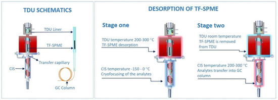
Figure 1.
Two-stage thermal desorption unit for thin film solid phase microextraction (TF-SPME) (photo courtesy of GERSTEL Inc.). For the purpose of clarity, the CIS (cooled injection system) is referred to as a cryo-trap in the text. TDU, thermal desorption unit; GC, gas chromatography.
The thermal desorption of TF-SPME devices is typically carried out by a two-stage device, as opposed to the simpler one-stage TD often used for small-volume phases, such as is the case of traditional SPME fiber devices. In two-stage TD, the first stage is responsible for the release of analytes from the extraction phase into the desorption unit. This first stage is in many ways equivalent to a one-stage TDU, however, there are more parameters to carefully optimize compared to traditional one-stage desorption (an example being a typical GC inlet). Opposed to only transferring the analyte directly into the column, with a two-stages desorption the analyte must be efficiently desorbed and transferred into the cryo-trap first, and then passed into the column. This requires optimization of the different split settings and temperature programming for each stage. The first stage, the TDU, is most often run at a constant temperature to desorb all compounds enriched on the TF-SPME device, however, a temperature ramp program is possible if desired. This temperature must then be optimized depending on the volatility of the analyte (typically recommended to be 50 °C below a compound boiling point) and the thermal stability of the extraction phase, the latter usually taking priority as different extraction phases require different thermal thresholds to desorb efficiently. In most instances, the lowest operating temperature that can be used for the desorption of enriched analytes with minimal carryover is optimal, as this approach prolongs the health of the TF-SPME device and minimizes the amount of bleed from the extraction phase. As an example, the operating temperatures for the two commercially available TF-SPME devices, Carboxen®/PDMS (Car/PDMS) and divinylbenzene/PDMS (DVB/PDMS), go up to 250 °C. This parameter, like many others, needs to be optimized by trial and error at the beginning of the analytical procedure. Additionally, the split ratio must be optimized like any other injector, however, as the TDU does not directly transfer analyte into the column but the cryo-trap, the split-mode of the TDU does not necessarily reflect the overall behavior of the injector. During desorption by way of the TDU, the analyte is transferred through a heated capillary to a cryo-trap. After desorption, the TDU is cooled and the TF-SPME device removed to ensure that no residual analyte is erroneously transferred from the TDU to the cryo-trap during the second stage. Furthermore, the heated transfer capillary connecting the TDU and cryo-trap should always be at a greater temperature than the highest temperature of the TDU to ensure complete transfer of all analyte into the cryo-trap, preferably 20–30 °C higher.
Contrary to one-stage desorption, in two-stage TD, after the first stage desorbs all volatile and semi-volatile compounds from the extraction phase, the second stage is used to pre-focus analytes before their introduction into the analytical column. This pre-focusing step, while a boon to any TD method, is especially crucial when desorbing large-volume phases due to the amount of analyte desorbed and the longer desorption times typically required. During the desorption of such large-volumes, as is the case of TF-SPME, the loss of highly-volatile compounds and ultra-volatiles during a single-stage desorption method would be unavoidable. The pre-focusing step is usually achieved by the inclusion of either a sorbent tube or temperature-controlled unit (here referred to as a cryo-trap). While a sorbent-based second-stage can exhibit suitable trapping capacities of analyte, the addition of a second sorbent can complicate method optimization and thus cryo-trap stages are generally preferred. Depending on the cryo-trap device used, the trap can be cooled by liquid gas (such as nitrogen and carbon dioxide) or a solid-state device. In the use of a cryo-trapping device, while the analytes are desorbed at high temperature in the TDU, the cryo-trap is held at a low temperature, −40 to 0 °C being appropriate for most volatiles [16,32,33] with highly volatile substances requiring lower temperatures trending toward −150 °C to properly pre-focus [8,19,29,34,35,36]. Only after all compounds are thermally desorbed from the TF-SPME device and condensed in the cryo-trap, the temperature of the cryo-trap is increased at a high rate (usually 12 °C/s), achieving discrimination-free transfer of analytes into the analytical column with minimal sample loss. Proper method development and TF-SPME workflow (Figure 2), with the use of a cryo-trap for the focusing of volatiles, results in sharper chromatographic peaks and ensures that all compounds extracted are introduced into the analytical column, increasing the reproducibility and sensitivity of the analytical method. In case of direct immersion extraction, it is advisable to gently wipe the TF-SPME device before introduction into the desorption liner, as to avoid potential matrix contaminants such as water and oil entering the TDU.
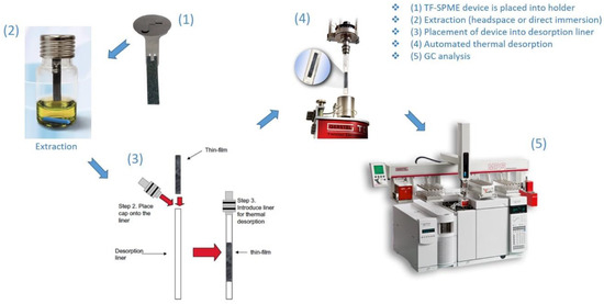
Figure 2.
Optimized TF-SPME workflow (photos courtesy of GERSTEL Inc.) for extraction and thermal desorption.
Care must be taken when deciding the type of split for the cryo-trap as it is synergistic with the TDU (Table 1). It should be mentioned that the gas flow of a two-stage unit is restricted by the cryo-trap during both stages. As a result, if splitless injection is desired a solvent-venting cryo-trap is still necessary to maximize gas flow, thus allowing efficient desorption. This solvent-vent must then be closed when the cryo-trap begins to increase in temperature, ensuring a splitless injection with maximum desorption efficiency. In short, for maximum sensitivity both stages should be run in splitless mode, the cryo-trap being operated under solvent-vent conditions before desorption into the column. In the presence of solvent, the cryo-trap can typically run in a mode that vents the solvent if the boiling point differs greatly from the analyte (approximately a 150 °C difference). This allows better chromatography with no loss of analyte, provided the boiling point temperature difference is sufficient and the cryo-trap is heated after the solvent vent closes, effectively making this method a splitless injection onto the column. For unknown analysis, it is typical to run both stages in split mode, and with concentrations in the ppm level, the TDU must have an appropriate split ratio with the cryo-trap being performed in either a splitless or solvent venting fashion.

Table 1.
Common parameters of two-stage thermal desorption and their applications.
It should be noted that alternative forms of TD for TF-SPME devices have been recently reported. These methods use “transmission mode” devices consisting of a coated mesh-like surface to enrich analytes and subsequently both desorb and ionize in one step using ambient ionization methods [37,38,39]. Direct analysis in real time (DART), an ambient ion source that has been shown to be well suited for onsite analysis [40], can be simply coupled to TF-SPME (coated mesh-like geometry) by positioning the device in-between the ion source and the mass spectrometer (MS). In this way, a stream of heated plasma (most often helium) desorbs the TF-S4PME transmission device while also ionizing analytes at the same time [37,38]. Another ambient ionization source, dielectric barrier discharge ionization (DBDI), has also been proven to be well suited for the analysis of illicit drugs using TF-SPME devices [39]. However, as the DBDI source does not thermally desorb compounds as the DART source can, a separate TD chamber was constructed using an aluminum body and temperature controller. This chamber was then filled with pre-humidified nitrogen to facilitate desorption, the flow of this now-analyte enriched gas entering the DBDI source [39].
4. Fundamentals of TF-SPME
SPME is one of the most attractive extraction techniques commonly used today due to its high throughput, low-cost and solvent-less extraction. In recent years, TF-SPME has been developed to better meet the demands of onsite and ultra-trace level analysis, as its high surface area-to-volume ratio enables it to achieve enhanced sensitivity and greater extraction efficiency [12]. In common with other extraction technologies, sampling using TF-SPME devices is characterized by partition equilibria between the free form of the analyte in a sample and the extraction phase constituting the extraction device. Consequently, the properties of the extraction phase play a significant role in the efficiency of the extraction process. The total amount of extracted analyte in direct immersion SPME, where the analyte equilibrates between only two phases, is described by Equation (1) [12]:
where is the total amount of extracted analyte at equilibrium, is the distribution constant of the analyte between the matrix and extraction phase, is the volume of extraction phase, is the volume of the sample and is the initial concentration of analyte in the sample. As can be seen in Equation (1), the greater the volume of the extraction phase , the larger amount of is extracted.
In the following equation describing the equilibrium time for the analyte between the two phases (Equation (2)) [12],
is the required time for the analyte to reach equilibrium with the extraction phase, t95% is the time needed to extract 95% of the equilibrium amount of an analyte on the device, is the thickness of the boundary layer, (b − a) represents the thickness of the extraction phase and is the diffusion constant of the analytes into the sample matrix. While an increase in allows higher extraction efficiency and thus greater sensitivity according to Equation (1), Equation (2) demonstrates that the corresponding increase in coating thickness results in a longer equilibrium time. Hence, it is important to optimize these parameters to ensure the most efficient and practical mode of extraction [41].
Considering Equation (3) [12],
A thin film geometry can also enhance the sampling rate due to its high surface area-to-volume ratio, reducing the time it takes to reach equilibrium and enhancing the capacity of the extraction device. In this equation, n is the amount analyte extracted over the extraction time t, A is the area of the extraction phase, is the diffusion constant of the analyte into the sample matrix and is the thickness of the boundary layer [42]. In other words, employing TF-SPME devices allows rapid sampling with high extraction capacity, suitable for ultra-trace level analysis.
5. Development of the First TF-SPME Device and Improvements up to 2019
As discussed previously, the simultaneous increase of extraction phase volume and surface area for TF-SPME devices allows enhanced sensitivity with as good or better extraction rates compared to traditional fiber SPME. The development of the underlying theory of this phenomena took root in 2000 when Semenov and colleagues described the kinetics of a thin layer of extraction phase, predicting what would be the driving force for both TF-SPME and passive sampler development [43]. While not a traditional TF-SPME device, the first technique to exploit a higher surface area-to-volume ratio to increase both extraction capacity and efficiency was developed in 2001 by Wilcockson and colleagues [31]. The procedure utilized a thin film (0.05 and 0.33 µm) of ethylene-vinyl acetate as the extraction phase which was coated onto 22 mm diameter glass disks serving as the support. This passive sampling method, exhibiting a surface area to volume ratio over 1000 times higher than comparable 100 µm SPME fibers, demonstrated faster equilibration times but with the caveat of having less phase volume. Due to the decreased phase volume, sensitivity did not exceed traditional SPME fibers, however, the method has still been adopted throughout the years with success as environmental passive samplers [44,45,46,47,48]. While important to the development of TF-SPME, this technique does not share the same geometry or sensitivity as traditional TF-SPME devices and thus is only mentioned due to its importance in the development of parallel sampling technologies based on thin adsorbent layers.
First developed in 2003 by Bruheim and colleagues [12], the first TF-SPME device consisted of a pre-manufactured 25.4 µm sheet of polydimethylsiloxane (PDMS) as the extraction phase. This thin sheet of PDMS was attached to a stainless steel rod as support, being affixed in a “flag-like” manner during extraction and wrapped around the rod prior to manual TD in a PTV GC inlet (Figure 3). Using polycyclic aromatic hydrocarbons (PAHs) as model analytes, the study demonstrated the practical use of TF-SPME as an alternative geometry to fiber SPME in both direct immersion extraction and headspace extraction. As the extraction efficiency was up to 20 times higher when using a 1 cm × 1 cm sheet of PDMS compared to a 100 µm PDMS fiber, with the extraction rate exceeding the already-developed SBSE [15], TF-SPME devices were further developed and optimized for better sensitivity and a more convenient sampling approach.
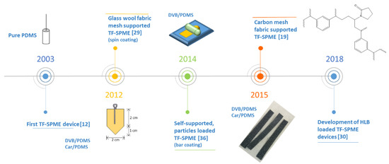
Figure 3.
A timeline of pivotal moments in the evolution of TF-SPME devices. PDMS, polydimethylsiloxane; DVB, divinylbenzene; Car, Carboxen®; HLB, hydrophilic-lipophilic balance.
Being limited to PDMS as an extraction phase, due to the availability of pre-made sorbents, priority was given in the geometric optimization of TF-SPME devices. In 2006, Bragg and colleagues modified a PDMS sheet into a 127 µm thick house-like shape (Figure 3) supported by a stainless steel wire [49]. This TF-SPME device, dimensions of 2 cm × 2 cm with the triangular portion of the device being 1 cm in height, boasted an increased phase volume of 0.0635 cm3 compared to the 0.00255 cm3 phase volume achieved by the previous developed TF-SPME device [12]. An increase of over 20 times the volume of the extraction phase, the achievable amount of extracted analyte was greatly increased, and thus greater sensitivity was attained. Moreover, the house-like geometry of the TF-SPME device permitted an increase in surface area while still allowing the device to be easily wrapped around the support, ensuring ease of injection into the GC inlet. Additionally, the same study demonstrated the efficacy of using TF-SPME for field analysis of aqueous media, establishing TF-SPME as a convenient onsite extraction tool [12].
A distinct departure from previous developments in both chemistry and design, Rodil and colleagues [32] demonstrated the use of glass wool fabric as solid support for TF-SPME. Opposed to previous attempts, which utilized pre-manufactured sheets of PDMS supported by steel wire, the SPME devices designed consisted of a polyacrylate (PA) extraction phase bound to glass wool. During the development of these devices, an amount of glass wool fabric was saturated with a solution of PA, being cured while sandwiched between two sheets of polyethylene foil to ensure homogeneity of the applied extraction phase. Being the first composite TF-SPME device developed, the sampling device demonstrated increased mechanical stability and the final device was 6 cm × 0.3 cm after the sheets of foil were removed. These TF-SPME devices, named “PA strips”, were compared to SBSE by performing their extraction with the same parameters and desorbing them into a TDU, very similar to the modern-day TD of TF-SPME devices. It was found, however, that these devices undergo thermal decomposition after multiple uses, resulting in high amounts of bleed into the GC and a lack of robustness of the device.
Incorporating the house-like geometry [49] and the glass fiber support [32] of earlier TF-SPME devices, Riazi et al. [29] developed the first mixed-mode extraction phase for TF-SPME using Car/PDMS and PDMS/divinylbenzene (PDMS/DVB). Adsorptive particles (Carboxen® or DVB) were suspended in a solution of the binding agent (PDMS) before being applied to a thin sheet of glass wool fabric. Instead of allowing the polymer solution to absorb into the supporting material as previous methods did [32], the coating procedure was performed using the spin coating method due to its ease of use and greater control over the phase thickness. After curing and cutting the material to a 2 cm × 2 cm square with a 1 cm triangle (same geometry developed by Bragg et al. [49]), the TF-SPME device was held by a cotter pin during extraction of analytes. This newly developed TF-SPME device was then desorbed into a large volume inlet (TDU-2, Gerstel GmbH, Mulheim, Germany) with a CIS-4 (Gerstel GmbH, Mulheim, Germany) cryo-trap. Accordingly, results showed a marked increase in the mechanical stability of the device during extraction, as well as improved thermal stability during the desorption process.
Building on the prior success of mixed-mode TF-SPME devices, the first self-supported particle loaded TF-SPME device was developed using DVB particles loaded onto PDMS [36]. This device was made with the intent of air-sampling using high amounts of DVB embedded into a PDMS base. It was found that when increasing the amount of DVB particles onto the PDMS membrane, up to 30% (w:w) DVB allows the membrane to achieve better mechanical stability compared to non-particle load membranes, 20% being found to be optimal for mechanical stability and extraction efficiency. As a result, the TF-SPME device boasted better sensitivity for the target analyte, benzene, than previous methods using fiber SPME or monophasic PDMS TF-SPME devices. This device, however, was still unable to appropriately be used in direct immersion extraction at high agitation rates, as the mechanical stability was not as great as previous glass-coated TF-SPME devices [29].
In 2016, Grandy and colleagues developed a sampler exhibiting far less siloxane bleed and greater robustness due to the carbon mesh support used therefore creating the first TF-SPME device well suited for untargeted analysis and onsite sampling by direct immersion extraction [19]. To achieve this, higher density PDMS was used to reduce bleed along with a slight reduction in phase volume. A mixture of two components, DVB particles embedded into PDMS, was then spread out onto a carbon mesh which primarily provided support along with some affinitive properties. In spite of the reduced phase volume of this device, the new design still afforded a highly sensitive extraction with now far lower siloxane bleed. Moreover, the carbon mesh support granted much better mechanical stability compared to previous iterations of TF-SPME, allowing the device to undergo more rigorous agitation compared to previously developed TF-SPME devices. After curing the extraction phase, the devices were then cut to different sizes well suited for TD, allowing more practical device introduction compared to previous methods. As a result of these recent developments, this version of TF-SPME is now the first commercially available TF-SPME device, currently distributed by GERSTEL Inc. (Gerstel GmbH, Mulheim, Germany). Since then, much of the development of TF-SPME devices has followed the same convenient format. Different extraction phases have been tested but not commercialized yet, including hydrophilic-lipophilic balance (HLB) phases that offer a wider range of extraction [30].
With the development of new mixed-mode extractive membranes that were both thermally and mechanically stable, new TF-SPME devices were able to overcome the limitations of previous variants of TF-SPME technology [12,16,32,49]. Initial devices, being made of pure monophasic extraction phase, exhibited poor structural rigidity making their practical application cumbersome in immersive extraction [12,49]. As a consequence of the large volumes of PDMS utilized in these devices, significant siloxane bleed was found, resulting in unacceptably high backgrounds. This was at times circumvented by use of single ion monitoring (SIM), avoiding detector saturation but nonetheless a technique not well suited for untargeted analysis. With the development of glass fiber supported TF-SPME devices [29,32], better structural rigidity was met, with the first device [32] still lacking suitable mechanical stability and thermal stability for repeated analysis. The second glass fiber supported device [29], however, not only achieved better mechanical and thermal stability compared to its earlier counterparts but also demonstrated a wider range of extraction than found previously by the use of mixed-mode extraction phases. While there is certainly a benefit of using glass fiber as a structural base for TF-SPME devices, the large amount of extraction phase and binder used is still cause of concern in terms of high siloxane backgrounds.
Further developments of TF-SPME devices have been focused on self-supported membranes with the incorporation of extractive particles, allowing them to achieve efficient extraction of a wide range of analytes. The incorporation of these extractive particles provided newfound mechanical stability [29], permitting the devices to be well suited for direct immersion extraction. Given that the qualities indispensable to the sampling method and characteristics important for the ruggedness of any GC-amenable extraction device—thermal stability, mechanical stability and extraction efficiency—were finally met, a refinement of TF-SPME as a whole was essential and further development was needed. Although it is true that the developed phases are thermally stable, a large volume of extraction phase will still cause more background and bleed compared to a smaller volume. In light of this, the newest iteration of TF-SPME devices [19], applying the extraction phase to a carbon mesh, solves this issue by retaining comparable sensitivity but with drastically reduced siloxane bleed, all the while being more mechanically stable than previous TF-SPME devices. As much as the geometry is far more convenient than previous iterations, the planar surface still poses a practical obstacle in the engineering of automated sampling and desorption. The major caveat in the new design is that currently only two phases currently are offered (DVB/PDMS and Car/PDMS).
6. TF-SPME Coating Methods
The various extraction phases and coating methods used in the development of TF-SPME devices (Figure 4) are chosen based on the chemical properties of the analyte, the surrounding matrix and the adopted desorption method. There are many techniques for the coating of TF-SPME devices, including dip coating [39,50], spin coating [51] bar coating [34,36,52], electrospinning [53] and spray coating [54]. Among these different coating methods, bar and spin coating are the most common coating methods for the production of TF-SPME devices amendable for TD. The most common coating method discussed in this review is bar coating in which the liquid extraction phase is set on a substrate and then this extraction phase is spread by a bar to develop the device [24]. The first TF-SPME device made by bar coating was prepared using DVB particles impregnated on PDMS and this device was later used for air sampling with good results [36]. Moving forward, Grandy et al. prepared bar coated DVB/PDMS onto a carbon-based mesh support coupled with a portable GC-MS for the quantitation of volatile and semi-volatile organic compounds [19]. The bar coating procedure is needed to be repeated on both sides of the carbon mesh support to ensure an even coating for the final device [9]. In 2017, Piri-Moghadam et al. used bar coating for the preparation of DVB/PDMS TF-SPME devices for the analysis of common pesticides in surface water samples. They found that the use of TF-SPME, in comparison to LLE, provided enhanced selectivity, reproducibility and faster rates of extraction [9]. In another study by Piri-Moghadam and colleagues in 2018, bar coating was utilized in the development of novel TF-SPME devices in an effort to analyze various pesticides found in river water, demonstrating a greener and more sensitive alternative than LLE [55]. The use of these developed DVB/PDMS TF-SPME devices for the quantification of pesticides demonstrated enhanced sensitivity and extraction efficiency for both onsite and bench-top analysis. In the spin coating method, in similar fashion to bar coating, a layer of extraction phase is placed on the substrate, after which by spinning the substrate, a thin layer of extraction phase is homogenously produced [24]. In both bar coating and spin coating, the thickness of the extraction phase can easily be controlled by the pressure of the bar onto the substrate and the intensity of spinning, respectively. Spray coating, one of the simplest methods for the preparation of TF-SPME devices, utilizes a dissolved mixture of extractive phase in a suitable solvent to be sprayed onto a stage until the formation of a uniform film [24]. An example of this technique, Mirnaghi et al. prepared polyacrylonitrile-polystyrene (PAN-PS)-DVB and polyacrylonitrile–phenylboronic acid (PAN-PBA) TF-SPME devices for the analysis of a variety of pharmaceuticals from human plasma [56]. Through the development of these two new TF-SPME devices for consequent analysis by LC-MS/MS, the analysis of a wide spectrum of polar compounds in human plasma with high efficiency and rapid throughput was achieved. Finally, another coating method which is often used for TD is electrospinning or electrospray coating. In this method, a mixture containing a polymer is sprayed by electrical energy on the surface of substrate [24]. In 2015, TF-SPME devices were prepared by the electrospinning method using polyimide nanofibers for the investigation and quantification of phenol compounds in environmental water using GC-MS [53]. Extraction devices were first activated by acetone, increasing hydrophilicity, resulting in greatly enhanced extraction efficiency with results demonstrating limits of quantification (LOQs) in the ppt level.
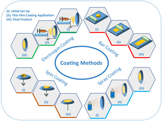
Figure 4.
The different coating methods for preparation of TF-SPME devices.
7. Applications
7.1. Environmental Analysis
The applications of TF-SPME have been traditionally environmental in nature, as much of their development has been expedited by the need for rugged and high capacity samplers, both passive and active. Initial progress toward highly efficient samplers with greater surface-to-volume ratios were developed to meet the need for the trace level extraction of contaminants found in complex environmental matrices, but these matrices proved to be challenging due to a variety of parameters such as large volumes for air analysis or the incredible sensitivity needed for persistent contaminants in aqueous media. Under these circumstances, the enhanced sensitivity of TF-SPME coupled with its convenient geometry for both extraction and introduction to onsite and benchtop instrumentation affords it the opportunity to outperform other SPME technologies in trace level environmental analysis.
Initial developments of membrane-based TF-SPME were evaluated by the extraction of polycyclic aromatic hydrocarbons (PAHs) from aqueous samples [12]. PAHs, a class of hydrophobic semivolatiles that are commonly released into the environment through the combustion of hydrocarbons and other organic matter, continue to rise in their environmental significance as they are readily distributed throughout biosystems and are a known cause of cancer among other mutagenic effects [57]. Since then, many studies have analyzed PAHs from aqueous samples using TF-SPME in various different modes, utilizing PDMS film [16,49,58,59], TF-SPME membrane [20] and an alternative thin film-based sampler using polymer-coated aluminum [45]. In addition, glass fiber reinforced TF-SPME has also been used for the analysis of PAHs in aqueous samples, using polyacrylate coatings to extract PAHs along with organochlorous and organophosphorus pesticides, demonstrating greatly enhanced efficiency with the partition coefficients for the TF-SPME device being up to 15 times higher than the SBSE device [32]. Less conventional extraction phases have also been introduced, as the recent success of carbonaceous nanomaterials being suitable extraction phases for SPME have led the path toward the development of mixed-mode carbonaceous TF-SPME devices. These carbonaceous TF-SPME devices have in turn been proven to be effective in the extraction of different organic compound classes, an example again being the analysis of PAHs in aqueous samples [20]. Furthermore, the analysis of PAHs have also been performed using other “parallel” thin film technologies, that is, extraction which utilizes a large surface area but does not exemplify the large phase volume needed for enhanced sensitivity. This is accomplished using PDMS-coated vials for the determination of PAHs in soil [46]. Similar alternative geometries have also been tested for their uses as passive samplers, such as ethylene-vinyl acetate (EVA) coated glass fibers for the aqueous extraction of pesticides [48] and EVA coated glass cylinders for the air sampling of volatile PCBs [44].
TF-SPME devices made of pure monophasic extraction phase, such as the first generation of TF-SPME devices [12], are still used in some studies as passive samplers. In the case of pyrethroids, a class of significantly hydrophobic insecticides that are known to cause damage to beneficial insects and fish, the suitability of TF-SPME has been just recently studied using thin films (25–500 µm) of different materials (silicon, polyethylene, polymethylmethacrylate, polyoxymethylene and polyurethane) as passive samplers [60]. Another alternative geometry of passive sampling, sorptive tape extraction (STE) [61], has also been effectively used for the direct sampling of plant volatiles [33,62] by both headspace and direct application to the plant surface. This geometry uses a tape-like PDMS thin film as a sampling device, providing an easy method of application for the non-invasive sampling of environmental and biological [61] matrices, recently being demonstrated by Boggia et al. [33] to be suitable for the analysis of herbivory-induced plant volatiles. While viewed currently as a passive sampling device, similar technology could be implemented in the development of new, more convenient TF-SPME devices.
During the development of particle-loaded TF-SPME devices, in this instance DVB particles in PDMS, Jiang et al. demonstrated the greatly enhanced sensitivity TF-SPME offers in trace air sampling and monitoring [36]. This particle loaded TF-SPME device was able to achieve extraction of a wide range of analytes with differing volatilities at high capacity. Furthermore, the study quantitatively samples benzene as a model analyte, a known carcinogen that is found commonly in fuels and smoking devices or from polluted air near a high-traffic road. Other more recent studies have confirmed the use of TF-SPME as a validated onsite sampling tool by its use in the analysis of biocides and UV blockers in sunscreen found in rivers, utilizing HLB/PAN and octadecyl (C18)/PAN TF-SPME devices [54]. Moreover, the efficacy of TF-SPME for the analysis of trace and ultra-trace level analysis in environmental matrices has been repeatedly tested and validated since its inception. In more recent times, since the development of carbon mesh-based TF-SPME devices, TF-SPME has been proven to be even more of a convenient sampling tool for onsite analysis due to the structural robustness of the device and its ease of introduction to portable instrumentation [19]. Since then, an interlaboratory study comparing these newly improved TF-SPME devices (DVB/PDMS on carbon mesh) to EPA-validated LLE methods demonstrated the efficacy of TF-SPME as a greener and more sensitive technique for the routine analysis of pesticides in water [55]. This comparative study by Piri-Moghadam and colleagues compared the suitability of different TF-SPME approaches to LLE. These approaches comprised of an in-bottle TF-SPME method using benchtop GC/MS, an onsite drill-assisted sampling that later used benchtop GC/MS and a procedure that used the same drill-assisted sampling as the previous but instead used a portable GC/MS to achieve both onsite sampling and onsite analysis. Results demonstrated (Table 2) the robustness of all TF-SPME-based methods, with the onsite extraction and analysis being the most environmentally friendly of all methods in the study [55]. In a similar fashion, the performance of TF-SPME has further been compared to other extraction methods, namely fiber SPME and SPE, in the analysis of harmful coal frothing agents that have been reportedly released into environmental waters and, by consequence, contaminated drinking water supplies. This study, the first to use a Car/PDMS TF-SPME device with carbon mesh support, was able to reliably extract multiple components of the coal frothing agent, crude (4-methylcyclohexyl)methanol (MCHM), along with a tentative metabolite with minimal sample manipulation. Results again showed TF-SPME devices to be more efficient at trace-level analysis than other methods (Table 2) [8]. Furthermore, with the development of novel HLB TF-SPME devices, Grandy and colleagues demonstrated the wide range of analytes that can be extracted by the analysis of chlorination byproducts in residential hot tubs [30].
Applications of TF-SPME devices using other modes of desorption have also been applied in the environmental sector. Recently, de la Calle and colleagues have utilized graphene TF-SPME devices coupled with chelating agents to sample various different metals in aqueous samples before analysis using total reflection X-ray fluorescence (TXRF) [28]. Similar methods have also employed similar TF-SPME-TXRF protocols with the use of nanomaterial TF-SPME devices [27]. In recent years, nanomaterial-based TF-SPME devices have been successfully applied to TD [63]. Mohammadi et al. demonstrated the use of a self-supported TF-SPME device composed of a zeolitic imidazolate framework, which extracts the organophosphorus pesticide ethion with subsequent TD for the analysis of environmental water samples [63]. In other respects, there are examples of more conventional TF-SPME being used in conjunction with LD for environmental analysis [64], ranging from the analysis of fluorinated benzoic acids in aqueous samples [21] to the analysis of polychlorinated biphenyls (PCBs) by direct application of a TF-SPME device into fish tissue [65].
7.2. Flavors and Fragrance Analysis
TF-SPME has various applications for the analysis of flavors and fragrances in a variety of different matrices. In this regard, Stuff and colleagues applied carbon mesh-supported DVB/PDMS as an extraction phase for the sampling of various volatile compounds, such as alcohols and ethyl esters [66]. The improved sensitivity for these various classes of compounds, afforded by TF-SPME, is essential for the rigorous demands of quality control in the beverage industry. A similar study by Vernarelli et al. investigated the efficacy of TF-SPME technology for the analysis of foodstuffs using DVB/PDMS TF-SPME devices and analyzed dark chocolate, cheeses and Caesar dressing [34]. These studies [34,66] compared the performance of TF-SPME to fiber SPME with the same stationary phase, revealing enhanced extraction efficiency and capacity for the TF-SPME devices. In 2016, another study investigated the fragrance of various essential volatile compounds from grapes, including linalool and 3-isobutyl-2-methoxypyrazine (IBMP), which were measured using PDMS-based TF-SPME devices [38]. This novel solid-phase mesh-enhanced sorption from headspace (SPMESH) method developed by Jastrzembski and colleagues resulted in greater throughput and enhanced limits of quantitation (ppb) during the analysis of volatile compounds (such as odorants) compared to other traditional methods. Sol-gel coating of a stainless steel mesh substrate with a thin film of PDMS provided great thermal stability and high sensitivity for the direct analysis with SPME-DART [38]. In 2007, Bicchi and coworkers compared the results of headspace and direct contact sorptive tape extraction (STE), all the while employing fiber HS-SPME as a reference standard [62]. The analytes extracted, volatile compounds found in various solid biological matrices such as apple, perfume on human skin, rosemary and spearmint, all demonstrated increased sensitivity and extraction efficiency compared to the more conventional fiber HS-SPME method.
7.3. Other Applications of TF-SPME
In addition to the diverse applications TF-SPME provides in the environmental and flavor/fragrance fields, many other procedures have been validated with a variety of matrices. Of these applications, one of the most striking uses of TF-SPME has been the analysis of sebum, developed by Sisalli and colleagues for the non-invasive detection of sebum in vivo [61]. This novel TF-SPME device, utilizing an adhesive thin layer of PDMS, demonstrated good performance in the extraction of sebum and other constituents of skin by a simple placement of the device on human skin, later being thermally desorbed in a TDU/cryo-trap system. This rapid and non-invasive sampling of human skin is crucial for the further development of sampling methods for the cosmetic and pharmaceutical industries. In a similar fashion, Jiang et al. introduced a novel in vivo sampling method for the analysis of human skin constituents using a thin layer of PDMS [35]. To prevent saturation of the device from sebum and other common skin oils, the PDMS-TF was emplaced between two pieces of stainless steel mesh and then placed on the surface of skin for sampling (Figure 5). As a result, this developed approach was able to demonstrate great promise for applications in clinical settings due to its high reproducibility and non-invasive sampling procedure. In another example of TF-SPME being well suited for both in vivo and ex vivo sampling in clinical settings, Bessonneau et al. prepared HLB/PDMS and (C18)/PDMS TF-SPME devices for the investigation of prohibited substances in saliva, analyzed with both LC-MS/MS and GC-MS [52]. Furthermore, this study demonstrated increased analytical precision compared to their similarly developed ex vivo method, confirming the need for more rugged in vivo sampling devices for clinical settings. In 2019, Shigeyama and colleagues reported another application of TF-SPME by use of zeolite-based devices for the extraction of volatile organic compounds (VOCs) in saliva, a class of compounds that is used to determine if a patient has oral cancer [67]. This study again demonstrated the robustness of TF-SPME devices as a non-invasive method. In a more recent study, Mirabelli et al. [39] utilized self-supported TF-SPME prepared according to the method proposed by Jiang et al. [36] to extract illicit drugs in both beverages and biofluids. In this study, for the first time, it was demonstrated that the DVB/PDMS TF-SPME devices were suitable for ultrasound-assisted extraction, with a consequent drastic reduction of extraction time prior to direct coupling to a DBDI source. Moreover, this approach allowed rapid quantitative desorption, reducing the likelihood of the thermal degradation of sensitive analytes. As a result, this newly developed method demonstrated several advantageous aspects, including rapid analytical throughput and enhanced sensitivity. With the simplicity for TF-SPME devices to be used as onsite samplers, along with their incredible sensitivity, they have been proven to be suitable tools for environmental analysis, while their fast and non-invasive sampling affords them great potential for both the pharmaceutical and clinical industries (Table 3).
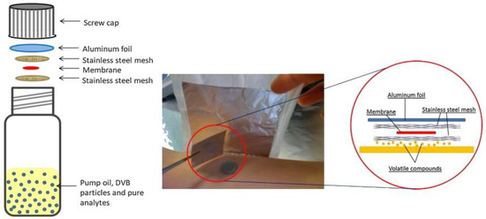
Figure 5.
The development of polydimethylsiloxane (PDMS) TF-SPME devices for the analysis of skin volatiles. Reproduced from [35], with permission from Elsevier, 2013.
Table 3.
Applications of TF-SPME and closely related devices.
Table 2.
Comparative studies demonstrating the efficacy of TF-SPME over similar extraction methods. Data are in limits of quantitation (LOQs) if not otherwise noted.
Table 2.
Comparative studies demonstrating the efficacy of TF-SPME over similar extraction methods. Data are in limits of quantitation (LOQs) if not otherwise noted.
| Piri-Moghadam et al. [9] | Rodriguez-Lafuente et al. [68] | Piri-Moghadam et al. [55] | Emmons et al. [8] | ||||||||||
|---|---|---|---|---|---|---|---|---|---|---|---|---|---|
| Compounds | TF-SPME Carbon Mesh Supported (µg L−1) | TF-SPME Non-Supported (µg L−1) | LLE (µg L−1) LOD | Compounds | Fiber SPME (µg L−1) RDL | Compounds | TF-SPME (ng L−1) | TF-SPME Drill Agitation (ng L−1) | LLE (ng L−1) | Compounds | TF-SPME (µg L−1) | SPME (µg L−1) | SPE (µg L−1) |
| 2,4,6-TCP | 0.050 | 0.025 | 0.50 | 2,4,6-TCP | 0.20 | 2,4,6-TCP | 10 | 100 | 500 | MCHM | 0.10 | 1.0 | 500 |
| 2,3,4,6-TeCP | 0.025 | 0.025 | 0.50 | 2,3,4,6-TeCP | 0.20 | 2,3,4,6-TeCP | 3.0 | 250 | 500 | MMCHC | 0.10 | 2.5 | 250 |
| Trifluralin | 0.050 | 0.050 | 1.0 | Trifluralin | 0.050 | Trifluralin | 3.0 | 50 | 1000 | 4MMCH | 1.0 | 2.5 | 500 |
| Diazinon | 0.050 | 0.050 | 1.0 | Diazinon | 0.50 | Diazinon | 100 | 1000 | 1000 | 1-4CHDM | 0.50 | 0.25 | 5000 |
| Triallate | 0.050 | 0.050 | 1.0 | Triallate | 0.050 | Triallate | 3.0 | 50 | 1000 | DM-1-4CHC | 0.10 | 0.50 | 500 |
| Methyl parathion | 0.50 | 0.50 | 1.0 | Methyl parathion | 0.20 | Methyl parathion | 100 | 1000 | 1000 | MCHCA | 2.0 | 2.50 | 25,000 |
| Alachlor | 0.50 | 0.050 | 0.50 | Alachlor | 0.10 | Alachlor | 10 | 100 | 500 | ||||
| Metalachlor | 0.050 | 0.025 | 5.0 | Metalachlor | 0.10 | Metalachlor | 3.0 | 250 | 500 | ||||
| Chlorpyrifos | 0.25 | 0.10 | 1.0 | Chlorpyrifos | 0.20 | Chlorpyrifos | 10 | 1000 | 1000 | ||||
| Cyanazine | 0.10 | 0.10 | 1.0 | Cyanazine | 1.0 | Cyanazine | 10 | 100 | 1000 | ||||
| 2,4-DCP | 0.10 | 0.050 | 0.25 | 2,4-DCP | 0.10 | ||||||||
| Bendiocarb | 0.050 | 0.025 | 2.0 | Bendiocarb | 0.05 | ||||||||
| Phorate | 0.25 | 0.25 | 0.5 | Phorate | 0.25 | ||||||||
| Carbofurane | 0.10 | 0.10 | 5.0 | Carbofurane | 0.20 | ||||||||
| Simazine | 0.25 | 0.25 | 1.0 | Simazine | 0.050 | ||||||||
| Atrazine | 0.075 | 0.25 | 0.50 | Atrazine | 0.050 | ||||||||
| PCP | 0.075 | 0.10 | 0.50 | PCP | 0.20 | ||||||||
| Terbufos | 0.25 | 0.25 | 0.50 | Terbufos | 0.50 | ||||||||
| Metribuzine | 0.25 | 0.10 | 5.0 | Metribuzine | 0.20 | ||||||||
| Carbaryl | 0.10 | 0.10 | 5.0 | Carbaryl | 0.50 | ||||||||
| Prometryn | 0.075 | 0.075 | 0.25 | Prometryn | 0.20 | ||||||||
| Malathion | 0.50 | 0.50 | 5.0 | Malathion | 0.20 | ||||||||
LLE, liquid-liquid extraction; SPE, solid phase extraction; LOD, limit of detection; RDL, reported detection limits.
8. Concluding Remarks and Future Directions
According to the principles of green analytical chemistry (GAC), the environmental impact of analytical methodologies should be minimized by reducing the amount of solvents used for sample pre-treatment and the use of toxic reagents, as well as developing alternative methodologies not requiring solvents and reagents [70]. As broadly discussed in this review article, TF-SPME, as an alternative geometry of SPME, is able to satisfy the requirements for greener sampling strategies yet providing ease of use, high-throughput workflows, extraction capability for trace analysis, robustness for onsite sampling, suitability for in vivo analysis and easy coupling to various separation platforms and direct MS analysis. When an analytical eco-scale for assessing the greenness of analytical procedures is performed [2,9] on conventional LLE methods, currently in use by regulatory agencies, versus newly developed TF-SPME-based approaches, the minimized use of organic solvents and production of laboratory waste allows TF-SPME to collect at least 50% less penalty points (based on parameters of an analytical process that are not in agreement with the ideal green analysis) compared to LLE. The versatility of the TF-SPME geometry both in the self-supported or supported devices enable this technique to fit various analytical needs for environmental, food and bioanalysis. As an example, TF-SPME can be used as wearable devices for passive sampling of skin emissions or as extractive probes for remote sampling by use of drones, when sampling sites are not easily reachable or their contamination levels could pose hazards to the analyst.
Due to the recent commercialization of carbon mesh supported TF-SPME devices, we envision that their use in academic and industrial premises will increase quickly in the upcoming years. Further work can be envisioned to test the ruggedness of these devices in complex fluids and evaluate their capabilities of performing multiple extraction/desorption cycles in these matrixes without significant loss of extraction efficiency. Moreover, further development of automation strategies for TF-SPME could aim for the complete automation of extraction/desorption cycles when needed, achieving the same throughput capabilities of fiber SPME.
Author Contributions
Conceptualization, E.G.; writing—original draft preparation, R.V.E. and R.T.; writing—review and editing, E.G. and R.V.E.; visualization, E.G., R.V.E. and R.T.; supervision, E.G.; funding acquisition, E.G.
Funding
This research received no external funding.
Acknowledgments
Conflicts of Interest
The authors declare no conflicts of interest.
References
- Tobiszewski, M.; Mechlińska, A.; Namieśnik, J. Green analytical chemistry—Theory and practice. Chem. Soc. Rev. 2010, 39, 2869–2878. [Google Scholar] [CrossRef] [PubMed]
- Gałuszka, A.; Migaszewski, Z.M.; Konieczka, P.; Namieśnik, J. Analytical Eco-Scale for assessing the greenness of analytical procedures. TrAC—Trends Anal. Chem. 2012, 37, 61–72. [Google Scholar] [CrossRef]
- Gałuszka, A.; Migaszewski, Z.; Namieśnik, J. The 12 principles of green analytical chemistry and the SIGNIFICANCE mnemonic of green analytical practices. TrAC—Trends Anal. Chem. 2013, 50, 78–84. [Google Scholar] [CrossRef]
- Spietelun, A.; Marcinkowski, Ł.; De La Guardia, M.; Namieśnik, J. Green aspects, developments and perspectives of liquid phase microextraction techniques. Talanta 2014, 119, 34–45. [Google Scholar] [CrossRef] [PubMed]
- Płotka-Wasylka, J. A new tool for the evaluation of the analytical procedure: Green Analytical Procedure Index. Talanta 2018, 181, 204–209. [Google Scholar] [CrossRef] [PubMed]
- Pawliszyn, J. Sample preparation: Quo vadis? Anal. Chem. 2003, 75, 2543–2558. [Google Scholar] [CrossRef] [PubMed]
- Mirnaghi, F.S.; Goryński, K.; Rodriguez-Lafuente, A.; Boyaci, E.; Bojko, B.; Pawliszyn, J. Microextraction versus exhaustive extraction approaches for simultaneous analysis of compounds in wide range of polarity. J. Chromatogr. A 2013, 1316, 37–43. [Google Scholar] [CrossRef] [PubMed]
- Emmons, R.; Devasurendra, A.; Godage, N.; Gionfriddo, E. Exploring the Efficiency of Various Extraction Approaches for Determination of Crude (4-methylcyclohexyl)methanol (MCHM) Constituents in Environmental Samples. LC-GC N. Am. 2019, 37, 27–34. [Google Scholar]
- Piri-Moghadam, H.; Gionfriddo, E.; Rodriguez-Lafuente, A.; Grandy, J.J.; Lord, H.L.; Obal, T.; Pawliszyn, J. Inter-laboratory validation of a thin film microextraction technique for determination of pesticides in surface water samples. Anal. Chim. Acta 2017, 964, 74–84. [Google Scholar] [CrossRef]
- Ouyang, G.; Pawliszyn, J. A critical review in calibration methods for solid-phase microextraction. Anal. Chim. Acta 2008, 627, 184–197. [Google Scholar] [CrossRef]
- Reyes-Garcés, N.; Gionfriddo, E.; Gómez-Ríos, G.A.; Alam, M.N.; Boyaci, E.; Bojko, B.; Singh, V.; Grandy, J.; Pawliszyn, J. Advances in Solid Phase Microextraction and Perspective on Future Directions. Anal. Chem. 2018, 90, 302–360. [Google Scholar] [CrossRef]
- Bruheim, I.; Liu, X.; Pawliszyn, J. Thin-film microextraction. Anal. Chem. 2003, 75, 1002–1010. [Google Scholar] [CrossRef]
- Kremser, A.; Jochmann, M.A.; Schmidt, T.C. PAL SPME Arrow—Evaluation of a novel solid-phase microextraction device for freely dissolved PAHs in water. Anal. Bioanal. Chem. 2016, 408, 943–952. [Google Scholar] [CrossRef]
- Yuan, Y.; Lin, X.; Li, T.; Pang, T.; Dong, Y.; Zhuo, R.; Wang, Q.; Cao, Y.; Gan, N. A solid phase microextraction Arrow with zirconium metal–organic framework/molybdenum disulfide coating coupled with gas chromatography–mass spectrometer for the determination of polycyclic aromatic hydrocarbons in fish samples. J. Chromatogr. A 2019, 1592, 9–18. [Google Scholar] [CrossRef]
- Baltussen, E.; Sandra, P.; David, F.; Cramers, C. Stir Bar Sorptive Extraction (SBSE), a Novel Extraction Technique for Aqueous Samples: Theory and Principles. J. Microcolumn Sep. 1999, 737–747. [Google Scholar] [CrossRef]
- Qin, Z.; Bragg, L.; Ouyang, G.; Pawliszyn, J. Comparison of thin-film microextraction and stir bar sorptive extraction for the analysis of polycyclic aromatic hydrocarbons in aqueous samples with controlled agitation conditions. J. Chromatogr. A 2008, 1196–1197, 89–95. [Google Scholar] [CrossRef]
- David, F.; Ochiai, N.; Sandra, P. Two decades of stir bar sorptive extraction: A retrospective and future outlook. TrAC—Trends Anal. Chem. 2019, 112, 102–111. [Google Scholar] [CrossRef]
- Yamaguchi, M.S.; McCartney, M.M.; Linderholm, A.L.; Ebeler, S.E.; Schivo, M.; Davis, C.E. Headspace sorptive extraction-gas chromatography–mass spectrometry method to measure volatile emissions from human airway cell cultures. J. Chromatogr. B Anal. Technol. Biomed. Life Sci. 2018, 1090, 36–42. [Google Scholar] [CrossRef]
- Grandy, J.J.; Boyaci, E.; Pawliszyn, J. Development of a Carbon Mesh Supported Thin Film Microextraction Membrane As a Means to Lower the Detection Limits of Benchtop and Portable GC/MS Instrumentation. Anal. Chem. 2016, 88, 1760–1767. [Google Scholar] [CrossRef]
- Mukhtar, N.H.; See, H.H. Carbonaceous nanomaterials immobilised mixed matrix membrane microextraction for the determination of polycyclic aromatic hydrocarbons in sewage pond water samples. Anal. Chim. Acta 2016, 931, 57–63. [Google Scholar] [CrossRef]
- Boyaci, E.; Goryński, K.; Viteri, C.R.; Pawliszyn, J. A study of thin film solid phase microextraction methods for analysis of fluorinated benzoic acids in seawater. J. Chromatogr. A 2016, 1436, 51–58. [Google Scholar] [CrossRef]
- Gionfriddo, E.; Boyacl, E.; Pawliszyn, J. New Generation of Solid-Phase Microextraction Coatings for Complementary Separation Approaches: A Step toward Comprehensive Metabolomics and Multiresidue Analyses in Complex Matrices. Anal. Chem. 2017, 89, 4046–4054. [Google Scholar] [CrossRef]
- Ghani, M.; Ghoreishi, S.M.; Salehinia, S.; Mousavi, N.; Ansarinejad, H. Electrochemically decorated network-like cobalt oxide nanosheets on nickel oxide nanoworms substrate as a sorbent for the thin film microextraction of diclofenac. Microchem. J. 2019, 146, 149–156. [Google Scholar] [CrossRef]
- Olcer, Y.A.; Tascon, M.; Eroglu, A.E.; Boyaci, E. Thin film microextraction: Towards faster and more sensitive microextraction. TrAC Trends Anal. Chem. 2019. [Google Scholar] [CrossRef]
- Walles, M.; Gu, Y.; Dartiguenave, C.; Musteata, F.M.; Waldron, K.; Lubda, D.; Pawliszyn, J. Approaches for coupling solid-phase microextraction to nanospray. J. Chromatogr. A 2005, 1067, 197–205. [Google Scholar] [CrossRef]
- Gómez-Ríos, G.A.; Reyes-Garcés, N.; Bojko, B.; Pawliszyn, J. Biocompatible Solid-Phase Microextraction Nanoelectrospray Ionization: An Unexploited Tool in Bioanalysis. Anal. Chem. 2016, 88, 1259–1265. [Google Scholar] [CrossRef]
- Romero, V.; Costas-Mora, I.; Lavilla, I.; Bendicho, C. Headspace thin-film microextraction onto graphene membranes for specific detection of methyl(cyclopentadienyl)-tricarbonyl manganese in water samples by total reflection X-ray fluorescence. Spectrochim. Acta—Part B At. Spectrosc. 2016, 126, 65–70. [Google Scholar] [CrossRef]
- De la Calle, I.; Ruibal, T.; Lavilla, I.; Bendicho, C. Direct immersion thin-film microextraction method based on the sorption of pyrrolidine dithiocarbamate metal chelates onto graphene membranes followed by total reflection X-ray fluorescence analysis. Spectrochim. Acta—Part B At. Spectrosc. 2019, 152, 14–24. [Google Scholar] [CrossRef]
- Riazi Kermani, F.; Pawliszyn, J. Sorbent coated glass wool fabric as a thin film microextraction device. Anal. Chem. 2012, 84, 8990–8995. [Google Scholar] [CrossRef]
- Grandy, J.J.; Singh, V.; Lashgari, M.; Gauthier, M.; Pawliszyn, J. Development of a Hydrophilic Lipophilic Balanced Thin Film Solid Phase Microextraction Device for Balanced Determination of Volatile Organic Compounds. Anal. Chem. 2018, 90, 14072–14080. [Google Scholar] [CrossRef]
- Wilcockson, J.B.; Gobas, F.A.P.C. Thin-film solid-phase extraction to measure fugacities of organic chemicals with low volatility in biological samples. Environ. Sci. Technol. 2001, 35, 1425–1431. [Google Scholar] [CrossRef]
- Rodil, R.; von Sonntag, J.; Montero, L.; Popp, P.; Buchmeiser, M.R. Glass-fiber reinforced poly(acrylate)-based sorptive materials for the enrichment of organic micropollutants from aqueous samples. J. Chromatogr. A 2007, 1138, 1–9. [Google Scholar] [CrossRef]
- Boggia, L.; Sgorbini, B.; Bertea, C.M.; Cagliero, C.; Bicchi, C.; Maffei, M.E.; Rubiolo, P. Direct Contact—Sorptive Tape Extraction coupled with Gas Chromatography—Mass Spectrometry to reveal volatile topographical dynamics of lima bean (Phaseolus lunatus L.) upon herbivory by Spodoptera littoralis Boisd. BMC Plant Biol. 2015, 15. [Google Scholar] [CrossRef]
- Vernarelli, L.; Whitecavage, J.A.; Stuff, J. Analysis of Food Samples using Thin Film Solid Phase Microextraction (TF-SPME) and Thermal Desorption GC/MS. 2019, 1–7. Available online: http://www.gerstel.com/pdf/AppNote-202.pdf (accessed on 30 July 2019).
- Jiang, R.; Cudjoe, E.; Bojko, B.; Abaffy, T.; Pawliszyn, J. A non-invasive method for in vivo skin volatile compounds sampling. Anal. Chim. Acta 2013, 804, 111–119. [Google Scholar] [CrossRef]
- Jiang, R.; Pawliszyn, J. Preparation of a particle-loaded membrane for trace gas sampling. Anal. Chem. 2014, 86, 403–410. [Google Scholar] [CrossRef]
- Gómez-Ríos, G.A.; Gionfriddo, E.; Poole, J.; Pawliszyn, J. Ultrafast Screening and Quantitation of Pesticides in Food and Environmental Matrices by Solid-Phase Microextraction-Transmission Mode (SPME-TM) and Direct Analysis in Real Time (DART). Anal. Chem. 2017, 89, 7240–7248. [Google Scholar] [CrossRef]
- Jastrzembski, J.A.; Sacks, G.L. Solid Phase Mesh Enhanced Sorption from Headspace (SPMESH) Coupled to DART-MS for Rapid Quantification of Trace-Level Volatiles. Anal. Chem. 2016, 88, 8617–8623. [Google Scholar] [CrossRef]
- Mirabelli, M.F.; Gionfriddo, E.; Pawliszyn, J.; Zenobi, R. Fast screening of illicit drugs in beverages and biological fluids by direct coupling of thin film microextraction to dielectric barrier discharge ionization-mass spectrometry. Analyst 2019, 144, 2788–2796. [Google Scholar] [CrossRef]
- Cho, D.S.; Gibson, S.C.; Bhandari, D.; McNally, M.E.; Hoffman, R.M.; Cook, K.D.; Song, L. Evaluation of direct analysis in real time mass spectrometry for onsite monitoring of batch slurry reactions. Rapid Commun. Mass Spectrom. 2011, 25, 3575–3580. [Google Scholar] [CrossRef]
- Piri-Moghadam, H.; Alam, M.N.; Pawliszyn, J. Review of geometries and coating materials in solid phase microextraction: Opportunities, limitations, and future perspectives. Anal. Chim. Acta 2017, 984, 42–65. [Google Scholar] [CrossRef]
- Jiang, R.; Pawliszyn, J. Thin-film microextraction offers another geometry for solid-phase microextraction. TrAC—Trends Anal. Chem. 2012, 39, 245–253. [Google Scholar] [CrossRef]
- Semenov, S.N.; Koziel, J.A.; Pawliszyn, J. Kinetics of solid-phase extraction and solid-phase microextraction in thin adsorbent layer with saturation sorption isotherm. J. Chromatogr. A 2000, 873, 39–51. [Google Scholar] [CrossRef]
- Harner, T.; Farrar, N.J.; Shoeib, M.; Jones, K.C.; Gobas, F.A.P.C. Characterization of polymer-coated glass as a passive air sampler for persistent organic pollutants. Environ. Sci. Technol. 2003, 37, 2486–2493. [Google Scholar] [CrossRef]
- Kennedy, K.E.; Hawker, D.W.; Müller, J.F.; Bartkow, M.E.; Truss, R.W. A field comparison of ethylene vinyl acetate and low-density polyethylene thin films for equilibrium phase passive air sampling of polycyclic aromatic hydrocarbons. Atmos. Environ. 2007, 41, 5778–5787. [Google Scholar] [CrossRef]
- Reichenberg, F.; Smedes, F.; Jönsson, J.A.; Mayer, P. Determining the chemical activity of hydrophobic organic compounds in soil using polymer coated vials. Chem. Cent. J. 2008, 2, 1–10. [Google Scholar] [CrossRef]
- Victoria Otton, S.; deBruyn, A.M.H.; Meloche, L.M.; Gobas, F.A.P.C.; Ikonomou, M.G. Assessing Exposure of Sediment Biota To Organic Contaminants By Thin-Film Solid Phase Extraction. Environ. Toxicol. Chem. 2008, 28, 247. [Google Scholar]
- St. George, T.; Vlahos, P.; Harner, T.; Helm, P.; Wilford, B. A rapidly equilibrating, thin film, passive water sampler for organic contaminants; Characterization and field testing. Environ. Pollut. 2011, 159, 481–486. [Google Scholar] [CrossRef]
- Bragg, L.; Qin, Z.; Alaee, M.; Pawliszyn, J. Field sampling with a polydimethylsiloxane thin-film. J. Chromatogr. Sci. 2006, 44, 317–323. [Google Scholar] [CrossRef]
- Godage, N.H.; Gionfriddo, E. A critical outlook on recent developments and applications of matrix compatible coatings for solid phase microextraction. TrAC—Trends Anal. Chem. 2019, 111, 220–228. [Google Scholar] [CrossRef]
- Guerra, P.; Lai, H.; Almirall, J.R. Analysis of the volatile chemical markers of explosives using novel solid phase microextraction coupled to ion mobility spectrometry. J. Sep. Sci. 2008, 31, 2891–2898. [Google Scholar] [CrossRef]
- Bessonneau, V.; Boyaci, E.; Maciazek-Jurczyk, M.; Pawliszyn, J. In vivo solid phase microextraction sampling of human saliva for non-invasive and on-site monitoring. Anal. Chim. Acta 2015, 856, 35–45. [Google Scholar] [CrossRef]
- Li, S.; Wu, D.; Yan, X.; Guan, Y. Acetone-activated polyimide electrospun nanofiber membrane for thin-film microextraction and thermal desorption-gas chromatography-mass spectrometric analysis of phenols in environmental water. J. Chromatogr. A 2015, 1411, 1–8. [Google Scholar] [CrossRef]
- Ahmadi, F.; Sparham, C.; Boyacl, E.; Pawliszyn, J. Time Weighted Average Concentration Monitoring Based on Thin Film Solid Phase Microextraction. Environ. Sci. Technol. 2017, 51, 3929–3937. [Google Scholar] [CrossRef]
- Piri-Moghadam, H.; Gionfriddo, E.; Grandy, J.J.; Alam, M.N.; Pawliszyn, J. Development and validation of eco-friendly strategies based on thin film microextraction for water analysis. J. Chromatogr. A 2018, 1579, 20–30. [Google Scholar] [CrossRef]
- Mirnaghi, F.S.; Pawliszyn, J. Development of coatings for automated 96-blade solid phase microextraction-liquid chromatography-tandem mass spectrometry system, capable of extracting a wide polarity range of analytes from biological fluids. J. Chromatogr. A 2012, 1261, 91–98. [Google Scholar] [CrossRef]
- Kim, K.H.; Jahan, S.A.; Kabir, E.; Brown, R.J.C. A review of airborne polycyclic aromatic hydrocarbons (PAHs) and their human health effects. Environ. Int. 2013, 60, 71–80. [Google Scholar] [CrossRef]
- Qin, Z.; Mok, S.; Ouyang, G.; Dixon, D.G.; Pawliszyn, J. Partitioning and accumulation rates of polycyclic aromatic hydrocarbons into polydimethylsiloxane thin films and black worms from aqueous samples. Anal. Chim. Acta 2010, 667, 71–76. [Google Scholar] [CrossRef]
- Qin, Z.; Bragg, L.; Ouyang, G.; Niri, V.H.; Pawliszyn, J. Solid-phase microextraction under controlled agitation conditions for rapid on-site sampling of organic pollutants in water. J. Chromatogr. A 2009, 1216, 6979–6985. [Google Scholar] [CrossRef]
- Xu, C.; Wang, J.; Richards, J.; Xu, T.; Liu, W.; Gan, J. Development of film-based passive samplers for in situ monitoring of trace levels of pyrethroids in sediment. Environ. Pollut. 2018, 242, 1684–1692. [Google Scholar] [CrossRef]
- Sisalli, S.; Adao, A.; Lebel, M.; Le Fur, I.; Sandra, P. Sorptive Tape Extraction—A Novel Sampling Method for the in vivo Study of Skin. LC-GC Eur. 2006, 19, 33–39. [Google Scholar]
- Bicchi, C.; Cordero, C.; Liberto, E.; Rubiolo, P.; Sgorbini, B.; Sandra, P. Sorptive tape extraction in the analysis of the volatile fraction emitted from biological solid matrices. J. Chromatogr. A 2007, 1148, 137–144. [Google Scholar] [CrossRef]
- Mohammadi, V.; Jafari, M.T.; Saraji, M. Flexible/self-supported zeolitic imidazolate framework-67 film as an adsorbent for thin-film microextraction. Microchem. J. 2019, 146, 98–105. [Google Scholar] [CrossRef]
- Wei, F.; Zhang, F.F.; Liao, H.; Dong, X.Y.; Li, Y.H.; Chen, H. Preparation of novel polydimethylsiloxane solid-phase microextraction film and its application in liquid sample pretreatment. J. Sep. Sci. 2011, 34, 331–339. [Google Scholar] [CrossRef]
- Jahnke, A.; Mayer, P.; Broman, D.; McLachlan, M.S. Possibilities and limitations of equilibrium sampling using polydimethylsiloxane in fish tissue. Chemosphere 2009, 77, 764–770. [Google Scholar] [CrossRef]
- Stuff, J.R.; Whitecavage, J.A.; Grandy, J.J.; Pawliszyn, J. Analysis of Beverage Samples using Thin Film Solid Phase Microextraction (TF-SPME) and Thermal Desorption GC/MS. 2018, 1–10. Available online: http://www.gerstel.com/pdf/AppNote-200.pdf (accessed on 30 July 2019).
- Shigeyama, H.; Wang, T.; Ichinose, M.; Ansai, T.; Lee, S.W. Identification of volatile metabolites in human saliva from patients with oral squamous cell carcinoma via zeolite-based thin-film microextraction coupled with GC–MS. J. Chromatogr. B Anal. Technol. Biomed. Life Sci. 2019, 1104, 49–58. [Google Scholar] [CrossRef]
- Rodriguez-Lafuente, A.; Piri-Moghadam, H.; Lord, H.L.; Obal, T.; Pawliszyn, J. Inter-laboratory validation of automated SPME-GC/MS for determination of pesticides in surface and ground water samples: Sensitive and green alternative to liquid–liquid extraction. Water Qual. Res. J. Canada 2016, 51, 331–343. [Google Scholar] [CrossRef]
- Jastrzembski, J.A.; Bee, M.Y.; Sacks, G.L. Trace-Level Volatile Quantitation by Direct Analysis in Real Time Mass Spectrometry following Headspace Extraction: Optimization and Validation in Grapes. J. Agric. Food Chem. 2017, 65, 9353–9359. [Google Scholar] [CrossRef]
- Armenta, S.; Garrigues, S.; de la Guardia, M. Green Analytical Chemistry. TrAC Trends Anal. Chem. 2008, 27, 497–511. [Google Scholar] [CrossRef]


© 2019 by the authors. Licensee MDPI, Basel, Switzerland. This article is an open access article distributed under the terms and conditions of the Creative Commons Attribution (CC BY) license (http://creativecommons.org/licenses/by/4.0/).