Article

Simulation of Helical-Baffle Inlet Structure Cyclone Separator

Beijing Institute of Spacecraft Environment Engineering, Beijing 100094, China
*
Author to whom correspondence should be addressed.
Separations 2025, 12(6), 166; https://doi.org/10.3390/separations12060166
Submission received: 19 March 2025 / Revised: 3 June 2025 / Accepted: 9 June 2025 / Published: 18 June 2025

Abstract

:
In developing spacecraft dust environment testing equipment, cyclone separators serve as critical particulate separation devices. To optimize cyclone performance, this study investigates the impact of inlet configurations on internal flow fields. We propose a novel helical-baffle inlet design and comparatively analyze it against volute baffle inlets and conventional single-channel inlets using Eulerian–Lagrangian multiphase simulations. Three-dimensional streamline visualization reveals internal flow patterns, while the Q-criterion identifies vortical structures. Results demonstrate that both volute and helical configurations effectively eliminate inlet gas funneling effects. The flow-splitting baffles mitigate flow field asymmetry, with the helical-baffle design exhibiting optimal performance: it maintains vortex stability, enhances fluid dynamic equilibrium, reduces pressure drop and improves separation efficiency to 95.92% for 4 μm particles.

1. Introduction

The Martian surface is extensively covered with dust deposits that are readily entrained by wind to form large-scale dust storms. Frequent Martian dust storms adversely affect the power systems of landers and rovers [1], with severe impacts on optical systems, mechanical assemblies, solar arrays, and thermal control systems—leading to performance degradation and safety risks [2]. Cosmic dust in outer space similarly jeopardizes spacecraft payloads [3] and poses significant threats to human space activities, particularly deep-space missions [4,5,6].
Figure 1 presents imagery of Martian dust storms: the left panel displays an event captured by ESA on April 2018, while the right panel shows an occurrence recorded by NASA on 14 March 2012.
Consequently, dust environment testing is essential during spacecraft development. This necessitates optimized design of dust separation systems for testing apparatus.
Cyclone separators—widely used for dust separation—employ centrifugal forces to segregate solid particles from gas–solid flows. Their advantages include structural simplicity, operational stability, low maintenance, and cost-effectiveness, enabling broad industrial applications. Pioneering research on high-efficiency cyclones dates to Stairmand’s foundational 1951 study [7].
Pressure drop and separation efficiency constitute two critical performance metrics for cyclone separators. Achieving reduced hydraulic resistance without compromising separation efficiency remains a primary research focus in cyclone optimization.
As industrial applications advance and research deepens, key deficiencies have been identified: conventional tangential inlet configurations exhibit inlet gas funneling effects, increasing energy dissipation during separation processes [8]. Volute inlet configurations typically mitigate this phenomenon. Figure 2 schematically compares both configurations.
Tian et al. [9] and He et al. [10] independently investigated downward-helical inlet configurations—a design lineage tracing back to industrial applications in the 1950s—which eliminate funneling effects while reducing pressure drop and preventing top dust ring formation, as visually documented in Figure 3.
Conventional single-inlet designs (tangential or volute) induce flow asymmetry. Ref [11] demonstrates the misalignment between aerodynamic vortex cores and geometric centers, increasing the pressure drop while promoting the vortex finder short-circuit flow, thereby reducing separation efficiency. Although symmetric double-inlet configurations resolve asymmetry, they introduce manufacturing and operational complexities. Wang et al. [12] addressed this through a volute inlet with an internal baffle (single-inlet double-channel design), with experimental and computational verification showing equivalent performance to double-inlet systems with superior manufacturability. Figure 4 schematically compares both configurations.
Liang et al. [13] confirmed that helical double-inlet configurations similarly enhance flow symmetry and separation efficiency while eliminating top dust rings, as visually documented in Figure 5
Analysis establishes that inlet symmetry critically governs flow stability: single inlets with baffle achieve symmetry comparable to double-inlet systems, while helical configurations prevent dust ring formation.
Therefore, this study proposes a novel helical inlet configuration integrated with a flow-splitting baffle. This design, alongside a volute inlet with baffle, serves as the primary research focus. We conduct numerical simulations to investigate these flow-symmetric inlet configurations, benchmarking them against conventional tangential inlets. The analysis examines three-dimensional velocity distributions within the cyclone separator under varying inlet configurations and compares key performance metrics. These findings aim to inform future structural optimization and performance enhancement of cyclone separators.

2. Mathematical Models and Simulation Methodology

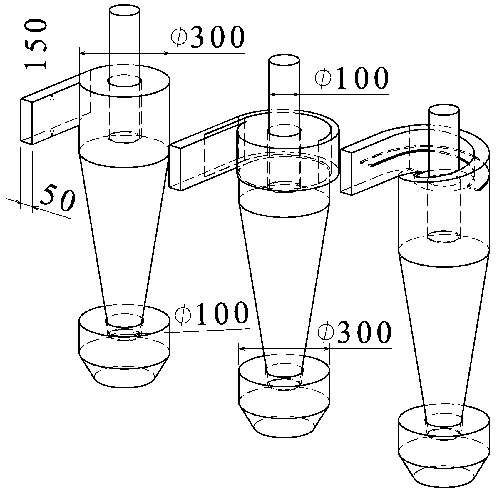
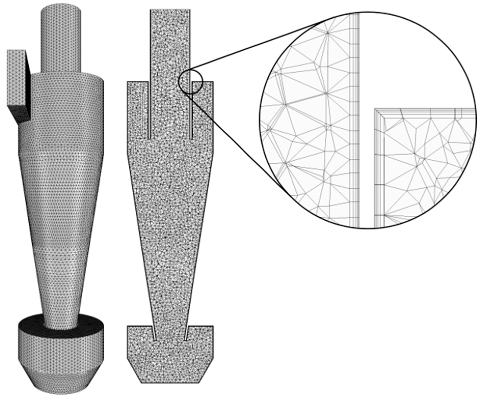
2.1. Geometric Modeling and Meshing

Figure 6 illustrates the three cyclone geometries: conventional (left), volute-baffle (center), and helical-baffle (right). All share identical barrel, conical section, vortex finder, and hopper dimensions with equal inlet cross-sections, differing only in inlet configuration:
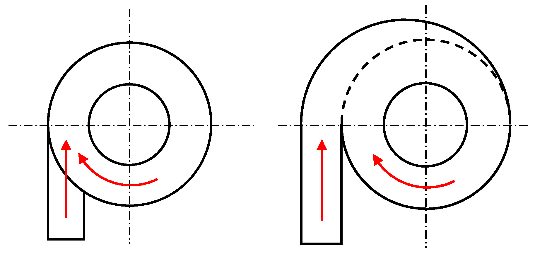
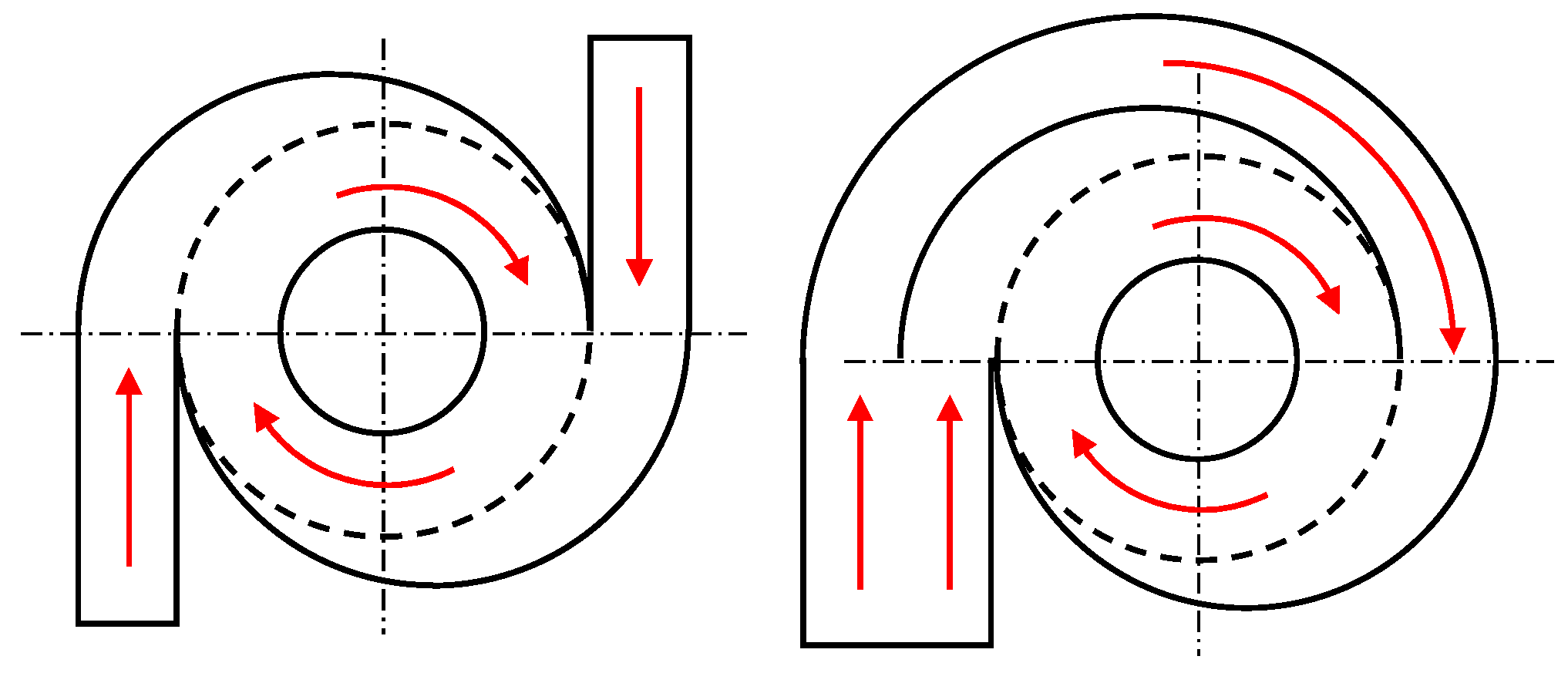
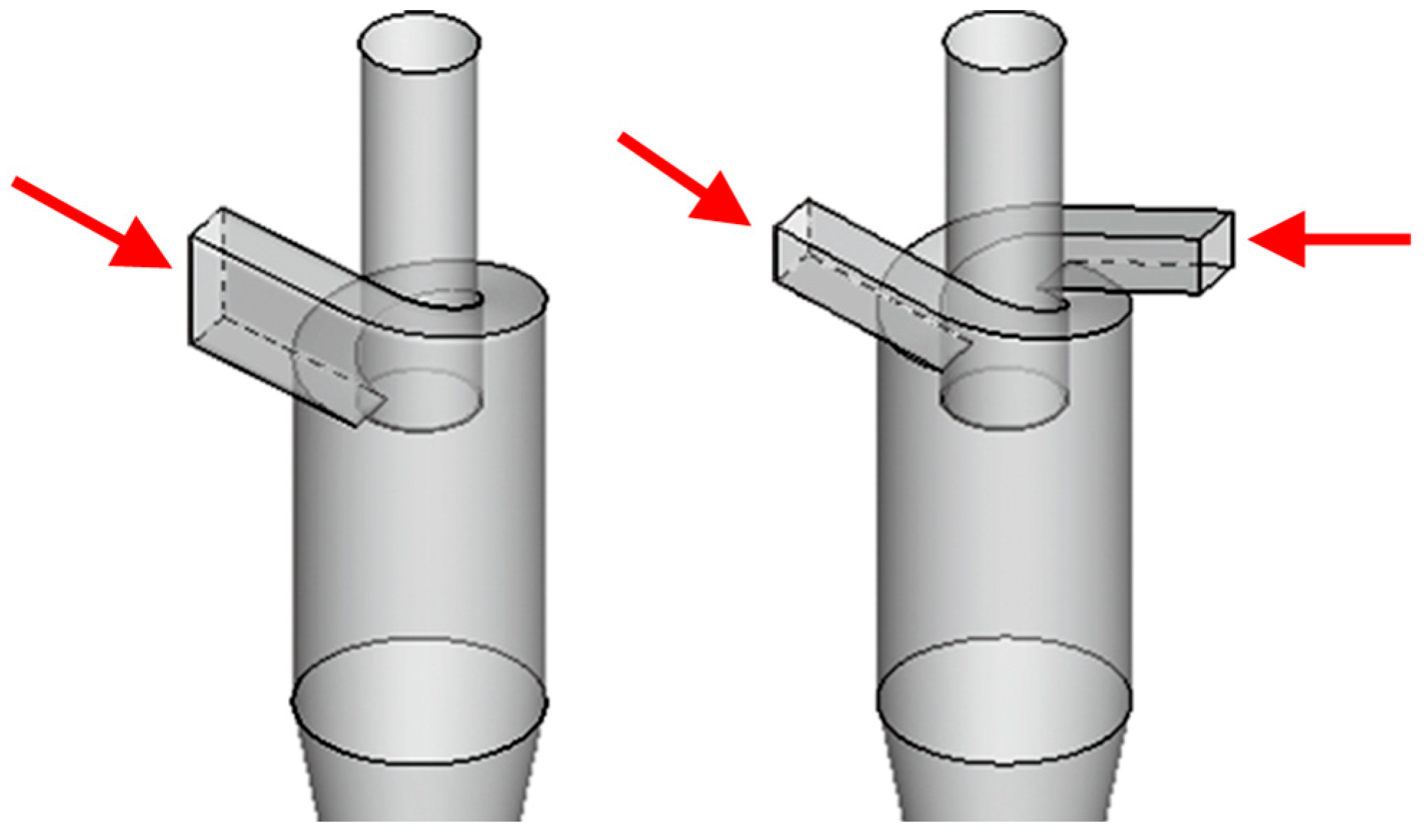
  • Conventional: Tangential penetration through barrel sidewall.
  • Volute-baffle inlet: Equidistant helical volute channel bifurcated by an internal splitter plate.
  • Helical-baffle inlet: Downward-deflected inlet circumferentially encircling vortex finder with helical splitter plate.
Given structural complexity, the computational domain was discretized using unstructured grids. Boundary layer meshing was implemented at walls due to particulate concentration near surfaces (Figure 7). The left panel shows global meshing, the center displays cross-sectional grids, and the right provides boundary layer magnification.

2.2. Mathematical Model

In gas–solid flows within cyclone separators, solid particles exhibit significant non-uniformity due to centrifugal forces. Given the low solid-phase concentration, the influence of dispersed particles on the continuous gas flow field is negligible. Consequently, this study employs a Lagrangian particle-tracking model for simulations [14]. This approach treats the gas phase as a continuum while modeling solid particles as a discrete phase, enabling detailed tracking of individual particle kinematics. Such methodology demonstrates distinct advantages in simulating sparse particle-laden flows.
The computational framework for the gas-phase flow field employs the Reynolds-Averaged Navier–Stokes (RANS) equations discretized using the finite volume method. This formulation decomposes instantaneous turbulent motion into mean and fluctuating components, with the latter exhibiting rapid temporal variations.
Core Equations of the RANS Framework include the following:
Continuity Equation:
ρ u ¯ = 0
Momentum Equation:
u ¯ t + u ¯ u ¯ = 1 ρ p ¯ + ν 2 u ¯ + u u ¯ + g
Based on studies investigating turbulence models for cyclone separators (e.g., Dhakal et al., 2014 [15]), which proposed highly accurate models for capturing complex anisotropic turbulence, the Reynolds Stress Model (RSM) was selected for turbulence closure in this study. This choice balances the imperative for accuracy in predicting the anisotropic turbulence characteristics inherent in the highly swirling flows within cyclone separators against computational cost considerations. While advanced curvature-corrected eddy-viscosity models (e.g., k-ω-v2) and Large Eddy Simulation (LES) demonstrated comparable or superior accuracy to RSM in specific cyclone configurations within the referenced literature, the RSM approach represents a well-established and computationally tractable standard for industrial cyclone simulations.
This model directly solves the transport equations for the Reynolds stress tensor u u ¯ , thereby fully preserving turbulence anisotropy effects, without the prohibitive expense of LES or the potential stability challenges of some newer formulations.
The pressure-strain term is modeled using the Quadratic Pressure-Strain Model, which is grounded in the Speziale–Sarkar–Gatski (SSG) framework. This formulation incorporates rotational flow correction terms to accurately resolve secondary vortices and turbulent kinetic energy redistribution mechanisms in strong swirl regimes.
This framework overcomes the limitations of linear eddy-viscosity models in strongly rotating flows, enabling accurate predictions of separator pressure drop and grade efficiency.
For the computation of solid particle trajectories, the dominant interphase forces considered are drag and pressure gradient forces. The drag coefficient is calculated using the Schiller–Naumann model.

2.3. Boundary Conditions

The gas phase boundary conditions are as follows: the inlet is set as the velocity inlet, 5 m/s, the outlet is the pressure outlet, and the wall boundary is set as the non-slip boundary condition.
The inlet of solid particles is set as velocity inlet, 5 m/s, mass flow rate 1 g/s, particle diameter 4 μm and 40 μm, density 2702 kg/m3, outlet as pressure outlet, walls with elastic rebound boundary conditions, and tangential and normal recovery coefficients are 1.

2.4. Declaration of Software Usage

The numerical simulations for this research were performed with ANSYS Fluent, leveraging its finite-volume-based solver architecture. This commercial software has been extensively validated for industrial-scale cyclone separator simulations.

3. Numerical Simulation Results

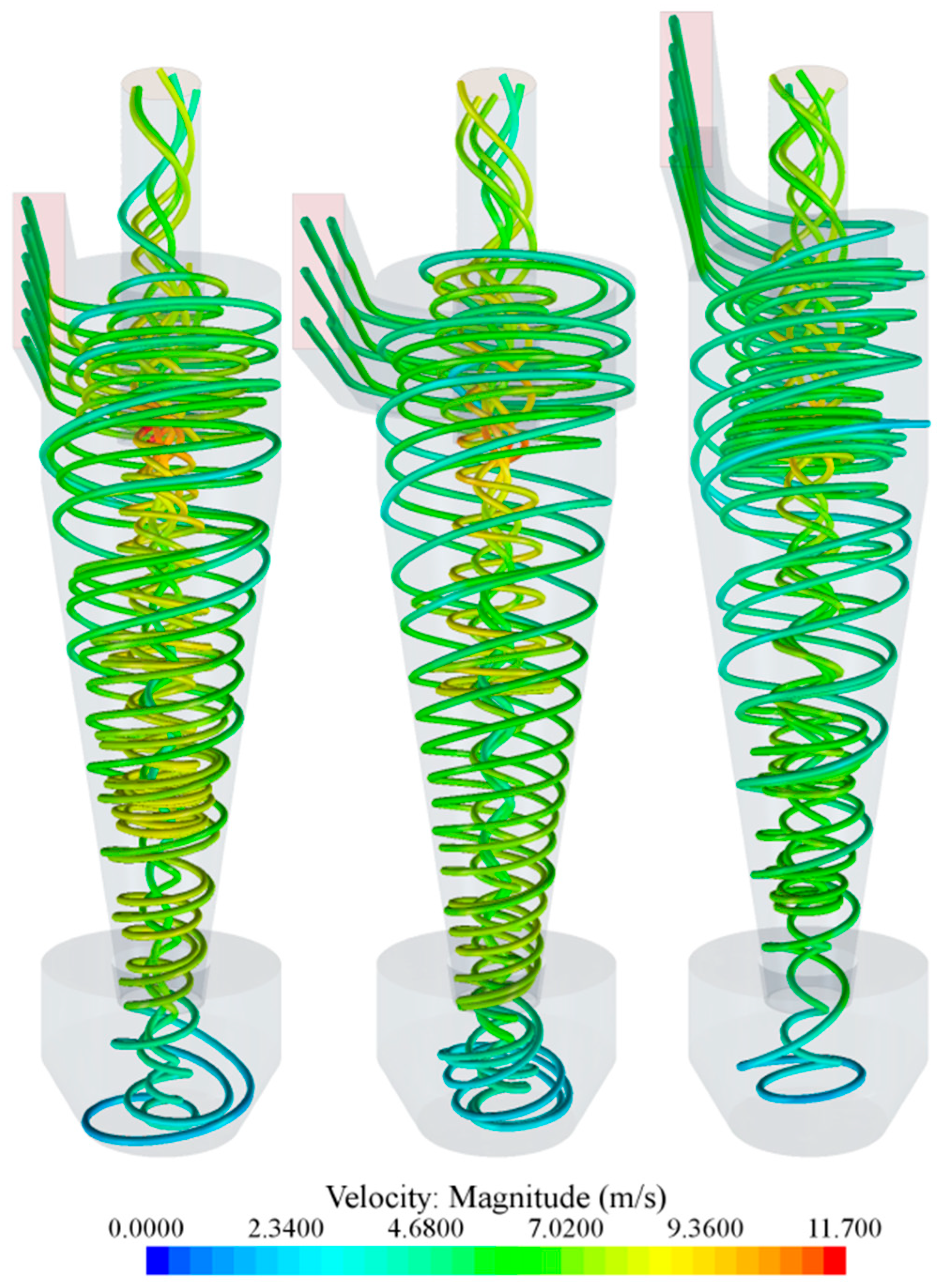
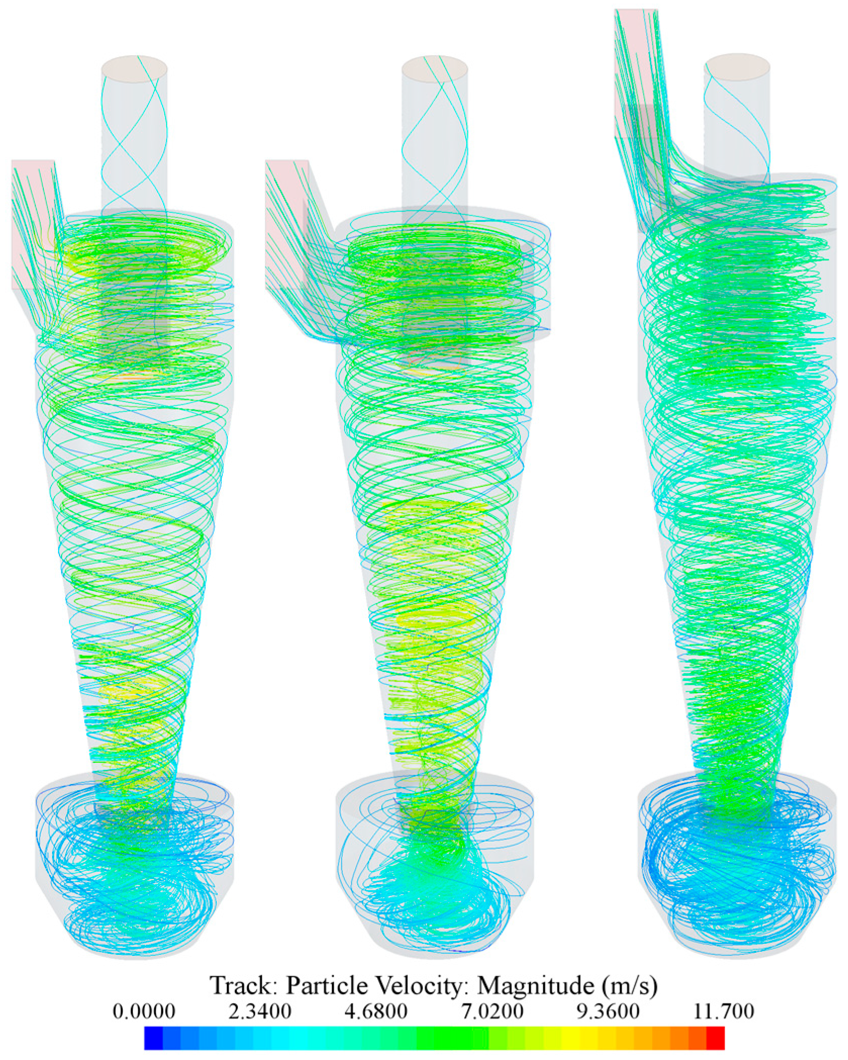
3.1. Three-Dimensional Streamline Visualization

The flow field within the cyclone separator exhibits considerable complexity, manifesting as a double helical structure with co-rotating but counter-directed helices about the central axis. This flow pattern originates from tangential gas injection along the separator wall, which creates a downward helical flow. The resulting central low-pressure region near the axis induces flow reversal at the conical section, causing a portion of the fluid to ascend through the core. During this ascent, shear forces from the outer rotating flow impart angular momentum, generating a co-rotating upward helical [16].
Figure 8 compares streamlines for different inlet configurations: conventional (left), volute (center), and helical (right). The conventional inlet demonstrates significant inlet gas funneling, where primary vortex constricts the incoming flow, accelerating local velocities and increasing pressure drop. The volute design achieves uniform inflow, substantially mitigating funneling effects. The helical inlet maintains continuous flow alignment with the internal vortex, eliminating funneling while establishing uniform velocity distribution (0–11.7 m/s) throughout the vessel.

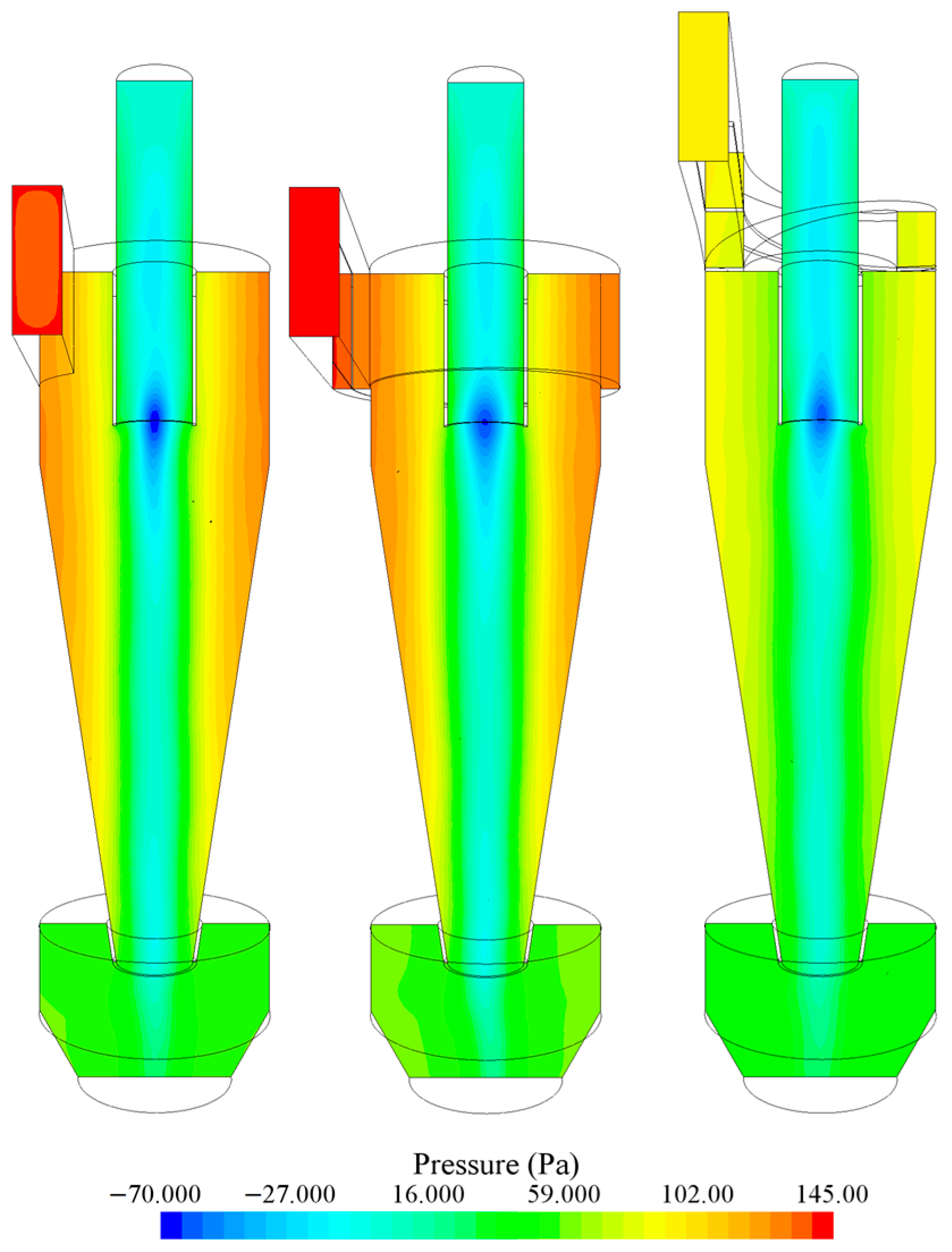
3.2. Pressure Distribution

Figure 9 presents static pressure distributions on mid-plane cross-sections and inlet planes for the three cyclone configurations. The conventional inlet exhibits significant pressure asymmetry in the upper cross-section (attributable to inlet gas funneling), with inlet plane pressure reaching 138 Pa. The volute inlet eliminates cross-sectional asymmetry through uniform inflow. While cross-section pressures resemble the conventional design, its elongated and constricted flow passage increases resistance, resulting in higher inlet pressure (145 Pa). The helical configuration achieves the lowest pressure drop (98 Pa inlet pressure), demonstrating superior performance.

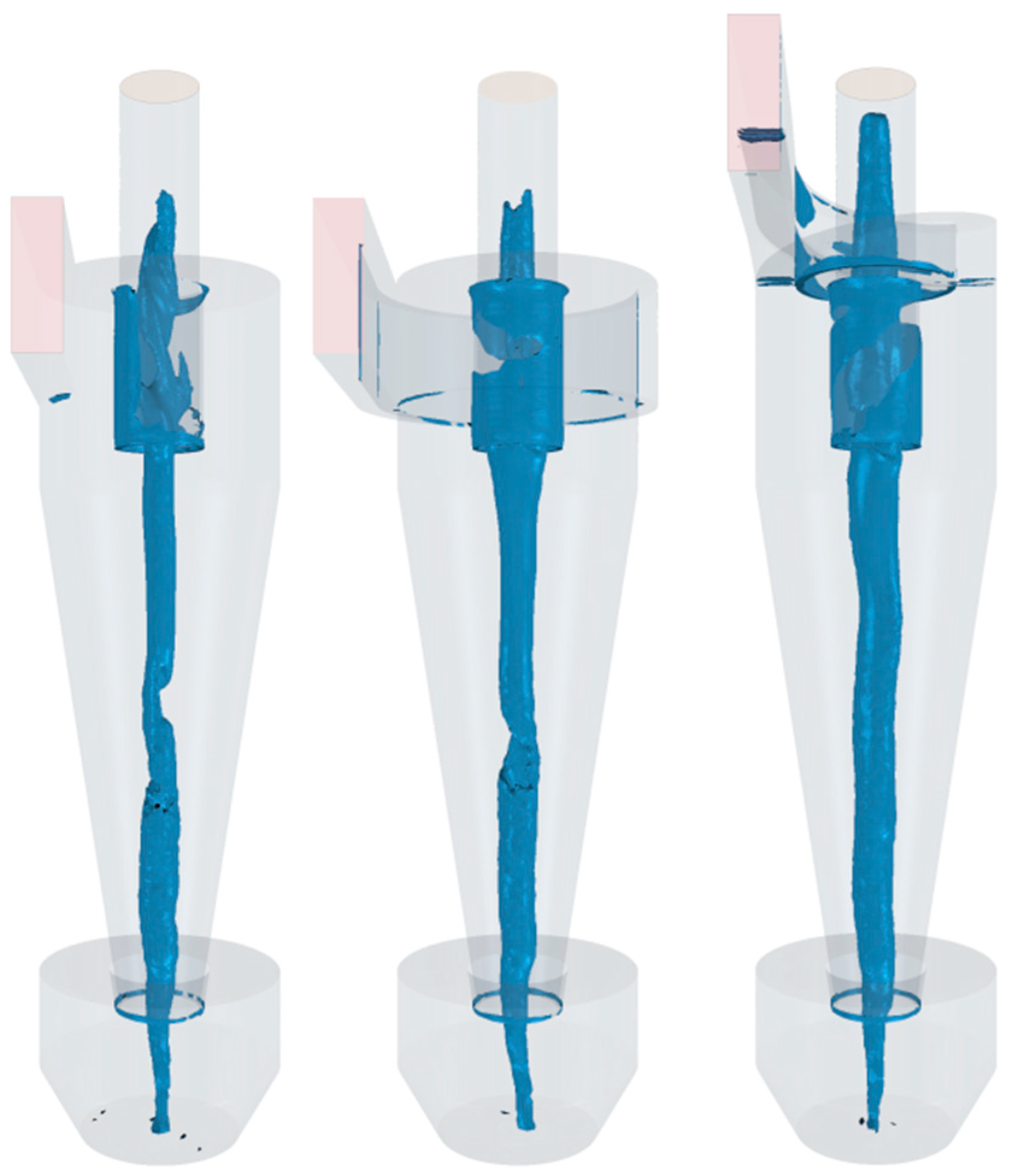
3.3. Vortex Core Morphology

Vortex structures were identified using the Q-criterion (Hunt et al., 1988), which quantifies rotational energy via the second invariant of the velocity gradient tensor [17]. The Q-criterion represents rotational energy per unit mass and per unit space–time-averaged vortex energy [18]. Higher Q values indicate stronger swirling intensity.
Iso-surfaces at Q = 50,000 s−2 (Figure 10) reveal distinct vortex core behaviors: the conventional design shows helical precession instabilities in the conical section, causing energy dissipation. The volute configuration stabilizes the vortex but retains mild helical distortion. The helical inlet produces an axially stable, smooth vortex core extending into the hopper without breakdown.

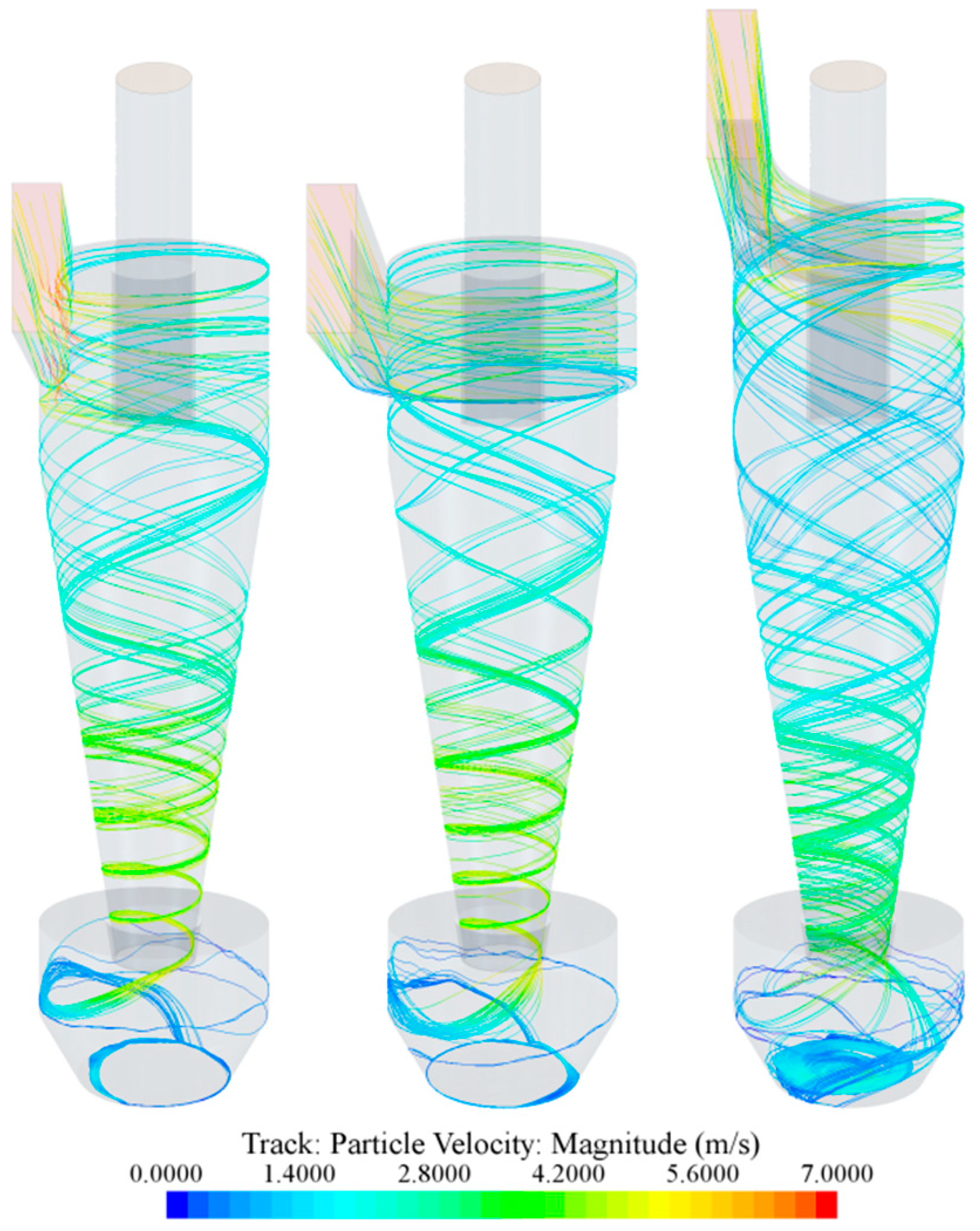
3.4. Particle Trajectory

Particle trajectories for 40 μm and 4 μm diameters are presented in Figure 11 and Figure 12, respectively. All configurations achieve complete separation of 40 μm particles, none fully capture 4 μm particles. Significant differences in grade efficiency exist (Table 1).
Both conventional and volute inlet configurations exhibit a pronounced top dust ring—a recirculation zone where particles sustain circular motion beneath the roof plate without gravitational settling. This phenomenon diminishes separation efficiency by prolonging particle residence and accelerates erosive wear through sustained particle-wall contact.
Helical configuration eliminates this ring through its inclined roof geometry, which fundamentally precludes planar recirculation. Reduced particle recirculation and shorter residence times (attributed to the absence of flow acceleration in Figure 8) enhance separation efficiency.

4. Discussion and Conclusions

Numerical simulations employing the Q-criterion yielded the following insights into flow dynamics and separation performance of three cyclone inlet configurations:
  • Inlet flow uniformity: The volute configuration mitigates inlet gas funneling, while the helical configuration eliminates it entirely, establishing axially consistent flow development.
  • Flowing performance: Despite improved symmetry, the volute configuration exhibits a higher pressure drop (145 Pa) than conventional (138 Pa) due to extended flow paths. The helical configuration achieves the lowest pressure loss (98 Pa).
  • Vortex stability: Helical vortex precession in conventional configuration causes energy dissipation. The helical configuration generates stable vortex cores without breakdown, evidenced by smooth Q-criterion iso-surfaces extending into the hopper.
  • Separation efficiency: Top dust ring formation in conventional/volute cyclones reduces 4 μm particle capture (91.43–92.50%). The helical configuration eliminates recirculation zones, achieving 95.92% efficiency through shorter particle trajectories.
This study presents a new helical-baffle inlet structure, which is simulated using the Eulerian–Lagrangian method for gas–solid two-phase flow. The results show that it has advantages in terms of internal flow field symmetry, vortex structure balance, and flow resistance. Further study will elucidate the vortices in cyclone separators, provide technical foundations for the design of new structure cyclone separators, and provide more choices for subsequent sand and dust testing of aerospace equipment and gas–solid separation processes across industries.

Author Contributions

Conceptualization, G.L. and J.G.; methodology, Z.W.; software, R.L.; formal analysis, R.L.; investigation, Z.W.; resources, J.G.; data curation, G.L.; writing—original draft preparation, G.L.; writing—review and editing, Z.W.; visualization, R.L.; supervision, J.G. All authors have read and agreed to the published version of the manuscript.

Funding

This research received no external funding.

Data Availability Statement

The raw data supporting the conclusions of this article will be made available by the authors on request.

Conflicts of Interest

The authors declare no conflict of interest.

References

  1. Cai, Z.; Qu, S. Space environment characteristics and key points in space environmental protection design for Mars probe mission. Spacecr. Environ. Eng. 2019, 36, 542–548. [Google Scholar]
  2. Jia, Y.; Li, Y.; Ji, L. Demands of Mars exploration missions on environmental simulation technologies. Spacecr. Environ. Eng. 2015, 32, 464–468. [Google Scholar]
  3. Wang, H.; Sun, C.; Ju, D.; Zhao, Y.; Wu, Y. Dust environmental detection in deep space explorations. Spacecr. Environ. Eng. 2019, 36, 549–557. [Google Scholar]
  4. Cui, H.; Guo, R.; Liu, R.; Xing, B.; Chen, L. The contamination of satellite optical device by space microparticles. Spacecr. Environ. Eng. 2017, 34, 566–570. [Google Scholar]
  5. Jiang, L.; Bai, Y. A Study on Effect of High-Speed Space Dust Collision on Transmittance of Optical Glass. Spacecr. Environ. Eng. 2005, 22, 215–218. [Google Scholar]
  6. Drolshagen, G. Impact effects from small size meteoroids and space debris. Adv. Space Res. 2008, 41, 1123–1131. [Google Scholar] [CrossRef]
  7. Stairmand, C.J. The design and performance of cyclone separators. Trans. Inst. Chem. Eng. 1951, 29, 356–383. [Google Scholar]
  8. Hoffmann, A.C. Gas cyclones and swirl tubes: Principles, design and operation. Appl. Mech. Rev. 2007, 56, B28. [Google Scholar] [CrossRef]
  9. Tian, P.; Li, S.; Zhang, Y.; Jin, Y.; Li, X.; Luo, Z. Experimental Analysis of High Efficiency, Low Resistance Cyclone Separator Inlet. China Powder Sci. Technol. 2010, 16, 7–11. [Google Scholar]
  10. He, H.; Huang, J. Numerical Simulations of Gas–Solid Flow in a Ramped Entrance Cyclone Separator. J. Combust. Sci. Technol. 2010, 16, 531–536. [Google Scholar]
  11. Song, J.; Wei, Y.; Shi, M. Analysis of Asymmetry of Gas-Phase Flow Field in Volute Cyclone. J. Chem. Ind. Eng. 2007, 58, 1091–1096. [Google Scholar]
  12. Wang, J.; Mao, Y.; Wang, J. Flow Characteristic in a Single Inlet Cyclone Separator With Double Passage. Acta Pet. Sin. Pet. Process. Sect. 2011, 27, 780–786. [Google Scholar]
  13. Liang, W.; Dai, S. Numerical simulation on flow field and separation efficiency of cyclone separator with helical-roof double inlet. Min. Process. Equip. 2018, 46, 6. [Google Scholar]
  14. Liu, W. Numerical Investigation on Performance of Vortex Tube Separator; Dalian Maritime University: Dalian, China, 2017. [Google Scholar]
  15. Dhakal, T.P.; Walters, D.K.; Strasser, W. Numerical study of gas-cyclone airflow: An investigation of turbulence modelling approaches. Int. J. Comput. Fluid Dyn. 2014, 28, 1–15. [Google Scholar] [CrossRef]
  16. Su, J.; Wang, L.; Gu, Z.; Zhang, Y. Simulation of cyclone separator using multiphase particle in cell method based on particle energy dissipation model. Chin. J. Environ. Eng. 2016, 10, 5735–5742. [Google Scholar]
  17. Hunt, J.C.; Wray, A.A.; Moin, P. Eddies stream and convergence zones in turbulent flows. Cent. Turbul. Res. Rep. CTR-S88 1988, 2, 193−208. [Google Scholar]
  18. Gao, Z.W.; Wang, J.; Wang, J.Y.; Mao, Y.; Li, J.; Wei, Y.D. Vortex Analysis for Cyclone Separators With Different Vortex Finder Diameters Based on Q Criterion. Acta Pet. Sin. Pet. Process. Sect. 2018, 34, 1172–1180. [Google Scholar]
Figure 1. Martian dust storm.
Separations 12 00166 g001
Figure 2. Tangential and volute inlet structure, the arrows indicate the flow direction.
Separations 12 00166 g002
Figure 3. Top dust ring phenomenon, the arrows indicate the flow direction.
Separations 12 00166 g003
Figure 4. Volute structure with double-inlet and baffle, the arrows indicate the flow direction.
Separations 12 00166 g004
Figure 5. Helical single-inlet and double-inlet configurations.
Separations 12 00166 g005
Figure 6. Geometric configurations.
Separations 12 00166 g006
Figure 7. Meshing diagram.
Separations 12 00166 g007
Figure 8. Streamline comparison scale: 0–11.7 m/s.
Separations 12 00166 g008
Figure 9. Pressure distribution scale: −75 to 145 Pa.
Separations 12 00166 g009
Figure 10. Vortex core structures Q = 50,000 s−2.
Separations 12 00166 g010
Figure 11. Here are 40 μm particle trajectories (velocity scale: 0–7 m/s).
Separations 12 00166 g011
Figure 12. Here are 4 μm particle trajectories (velocity scale: 0–11.7 m/s).
Separations 12 00166 g012
Table 1. Grade efficiency for 4 μm particles across configurations.
ConventionalVoluteHelical
91.43%92.50%95.92%
Disclaimer/Publisher’s Note: The statements, opinions and data contained in all publications are solely those of the individual author(s) and contributor(s) and not of MDPI and/or the editor(s). MDPI and/or the editor(s) disclaim responsibility for any injury to people or property resulting from any ideas, methods, instructions or products referred to in the content.

