
Accumulation of Particles in an Annular Centrifugal Contactor Cascade and the Effect upon the Extraction of Nitric Acid

 ,
,  ,
,
Abstract

1. Introduction
2. Materials and Methods
2.1. Materials and Chemicals
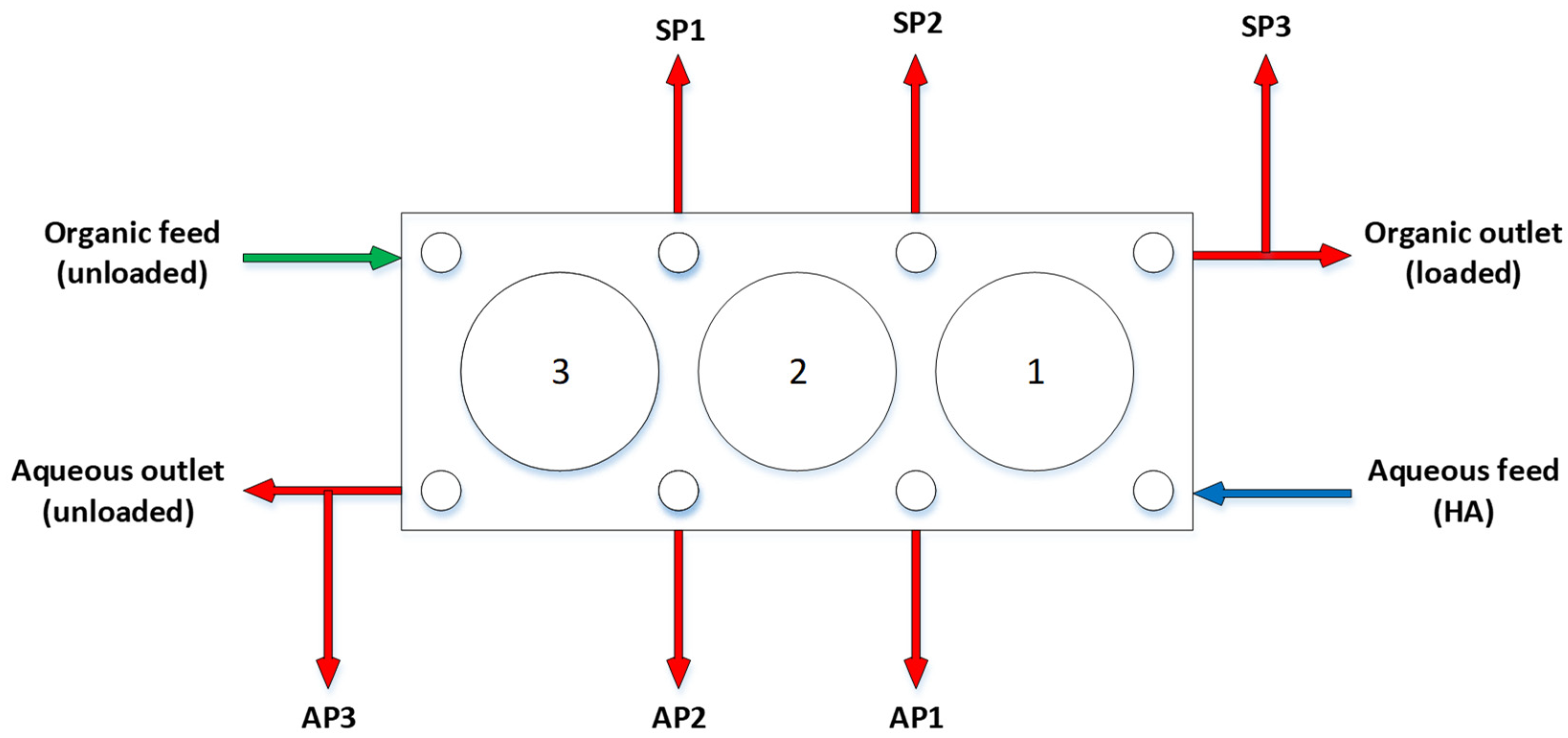
2.2. Description of Rig
2.3. Operation of the Rig
- The organic feed tank was charged with 30 % TBP/OK.
- The aqueous feed tank was charged with 1 M nitric acid, which was agitated with an overhead mixer set at 15 Hz. Solid Al2O3 particles were added to the agitated aqueous feed tank via a funnel to obtain the particle suspension.
- The CC rotors in the cascade were set at 2000 rpm.
- Then, the suspended particle aqueous feed was pumped at 10 L/h through the cascade. Upon elution via the aqueous outlet, the organic feed began pumping at 10 L/h through the cascade to achieve a solvent–aqueous ratio of 1:1.
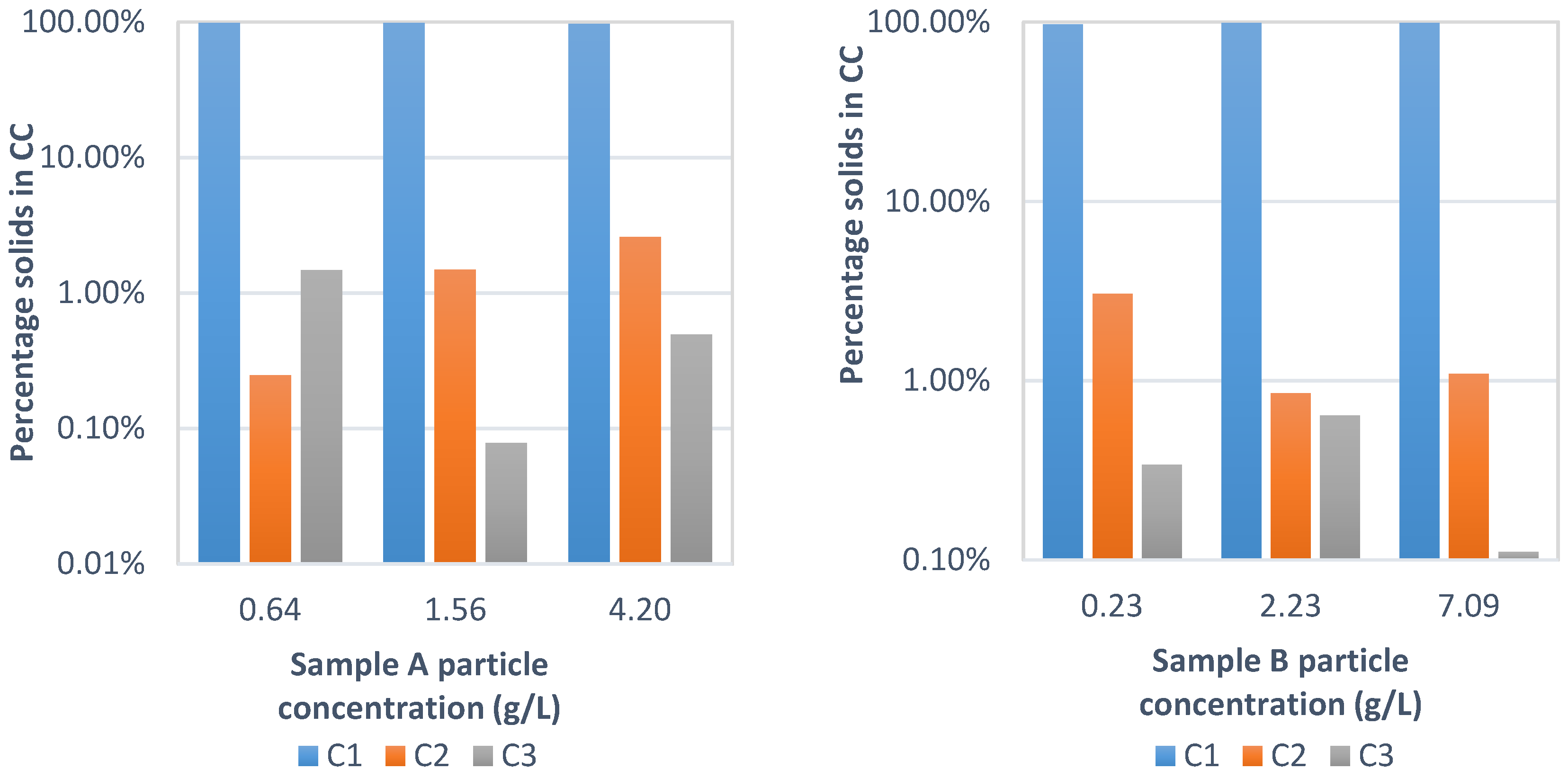
- Aqueous samples were taken at 20 min intervals from sampling ports between each stage, shown in Figure 1. The sample acidity was determined by the titration stated in the materials and chemicals section.
- Both the pumps and the CC rotors were stopped immediately at the end of the experiment. The experiment was stopped after a specified time or when the agitator approached a state of being no longer submersed in the aqueous feed solution.
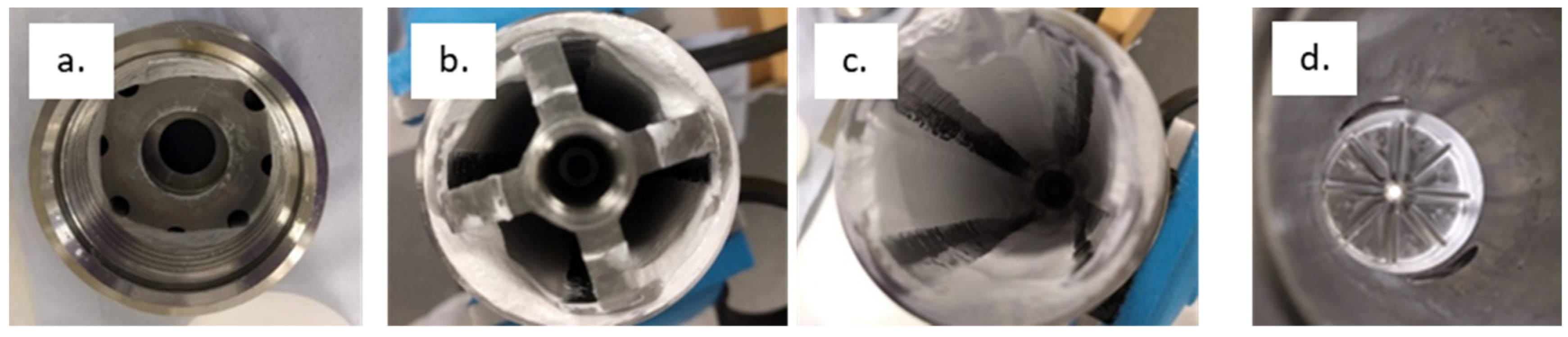
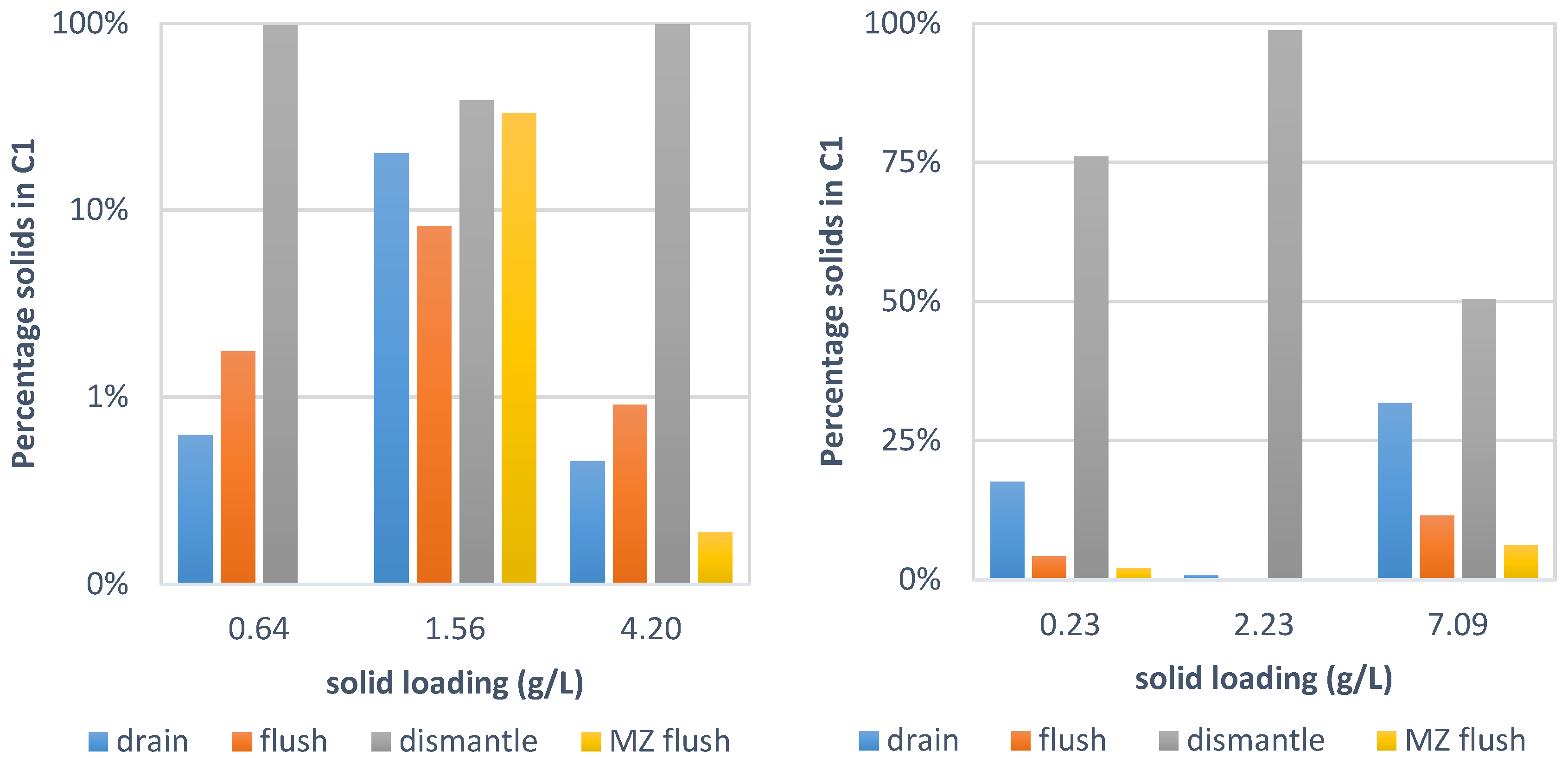
- The contactors were emptied and flushed to determine the quantity of particles held up in each stage. It was necessary to dismantle and flush particles from the separator rotor to recover the majority of the particles. The particle masses from each contactor were collected using the following process:
- The contactors were drained via their bottom valves.
- The contactors were then flushed with 100 mL of water via the vent, further detailed in the Supporting Information.
- The contactors were dismantled, first by removing the motor, then by removing the rotor assembly, then by removing the centrifuge rotor from rotor assembly. The centrifuge rotor was opened, and the particle cakes that were formed were washed out and the particles were collected.
- The mixing zone, without the contactor inserted, was flushed, and particles were collected. Any particles collected were allowed to settle, the supernatant was decanted, the particles were dried overnight in an oven at 85 °C, and the mass was measured.
2.4. Experimental Matrix
3. Results and Discussion
Impact of Particles on Nitric Acid Extraction
4. Conclusions
Supplementary Materials
Author Contributions
Funding
Data Availability Statement
Acknowledgments
Conflicts of Interest
References
- Baker, A.; Fells, A.; Carrott, M.J.; Maher, C.J.; Hanson, B.C. Process intensification of element extraction using centrifugal contactors in the nuclear fuel cycle. Chem. Soc. Rev. 2022, 51, 3964–3999. [Google Scholar] [CrossRef] [PubMed]
- Hamamah, Z.A.-K.; Grützner, T. Hydrodynamics Study on Annular Centrifugal Contactors: CINC V 02 as an Example. Chem. Eng. Technol. 2023, 46, 567–578. [Google Scholar] [CrossRef]
- Hamamah, Z.A.; Grützner, T. Liquid-Liquid Centrifugal Extractors: Types and Recent Applications—A Review. ChemBioEng Rev. 2022, 9, 286–318. [Google Scholar] [CrossRef]
- Leonard, R.A. Recent advances in centrifugal contactor design. Sep. Sci. Technol. 1988, 23, 1473–1487. [Google Scholar] [CrossRef]
- Carrott, M.; Maher, C.; Mason, C.; Sarsfield, M.; Whittaker, D.; Taylor, R. Experimental Test of a Process Upset in the EURO-GANEX Process and Spectroscopic Study of the Product. Solvent Extr. Ion Exch. 2022, 41, 1–30. [Google Scholar] [CrossRef]
- Hamamah, Z.A.-K.; Grützner, T. Development of a Procedure for Defining the Operational Window of Annular Centrifugal Contactors. Available online: https://ssrn.com/abstract=4784721 (accessed on 9 May 2024).
- Ritzler, P.M.; Weiss, C.K.; Seyfang, B.C. One-Dimensional Modeling of Mass Transfer Processes in an Annular Centrifugal Contactor. ChemEngineering 2023, 7, 59. [Google Scholar] [CrossRef]
- Leonard, R.A. Design principles and applications of centrifugal contactors for solvent extraction. In Ion Exchange and Solvent Extraction: A Series of Advances; CRC Press: Boca-Raton, FL, USA, 2010; pp. 563–616. [Google Scholar]
- Baker, A.; Fells, A.; Maher, C.J.; Hanson, B.C. The effect of size and shape of annular centrifugal contactors upon hydrodynamics and mass transfer using HNO3-TBP/OK. Prog. Nucl. Energy 2024, 167, 104966. [Google Scholar] [CrossRef]
- Su, Y.; Tang, J.; Yang, X.; Wang, R. Effect of geometrical parameters on extraction efficiency of the annular centrifugal contactor. Separations 2021, 8, 102. [Google Scholar] [CrossRef]
- Duan, W.H.; Zhao, M.; Wang, C.; Cao, S. Recent Advances in the Development and Application of Annular Centrifugal Contactors in the Nuclear Industry. Solvent Extr. Ion Exch. 2014, 32, 1–26. [Google Scholar] [CrossRef]
- Baker, A.; Fells, A.; Shaw, T.; Maher, C.J.; Hanson, B.C. Effect of Scale-Up on Residence Time and Uranium Extraction on Annular Centrifugal Contactors (ACCs). Separations 2023, 10, 331. [Google Scholar] [CrossRef]
- Baker, A.; De Santis, A.; Fells, A.; Hunter, T.; Hanson, B.; Maher, C.; Taylor, R. The development of centrifugal contactors: Next generation solvent extraction equipment for advanced reprocessing of nuclear fuels. Nucl. Future 2022, 3, 38–54. [Google Scholar]
- Seyfang, B.C.; Klein, A.; Grützner, T. Extraction Centrifuges—Intensified Equipment Facilitating Modular and Flexible Plant Concepts. Chem. Eng. J. 2019, 3, 17. [Google Scholar] [CrossRef]
- Abduh, M.Y.; van Ulden, W.; Kalpoe, V.; van de Bovenkamp, H.H.; Manurung, R.; Heeres, H.J. Biodiesel synthesis from Jatropha curcas L. oil and ethanol in a continuous centrifugal contactor separator. Eur. J. Lipid Sci. Technol. 2013, 115, 123–131. [Google Scholar] [CrossRef]
- Kraai, G.; Schuur, B.; Van Zwol, F.; Van de Bovenkamp, H.; Heeres, H. Novel highly integrated biodiesel production technology in a centrifugal contactor separator device. Chem. Eng. J. 2009, 154, 384–389. [Google Scholar] [CrossRef]
- Angelis, A.; Michailidis, D.; Antoniadi, L.; Stathopoulos, P.; Tsantila, V.; Nuzillard, J.-M.; Renault, J.-H.; Skaltsounis, L.A. Pilot continuous centrifugal liquid-liquid extraction of extra virgin olive oil biophenols and gram-scale recovery of pure oleocanthal, oleacein, MFOA, MFLA and hydroxytyrosol. Sep. Purif. Technol. 2021, 255, 117692. [Google Scholar] [CrossRef]
- Johannsen, J.; Engelmann, C.; Liese, A.; Fieg, G.; Bubenheim, P.; Waluga, T. Pilot-scale Operation of a Multi-Enzymatic Cascade Reaction in a Multiphase System. Chem. Eng. Trans. 2020, 79, 25–30. [Google Scholar]
- Wan, Q.; Chen, K.; Zhu, J.; Wu, B.; Ji, L.; Wu, Y. Separation and Purification of Bitespiramycin by Counter-Current Extraction. Sep. Sci. Technol. 2015, 50, 2649–2657. [Google Scholar] [CrossRef]
- Duan, W.H.; Zhou, X.; Zhang, C. Extraction of Hydrocortisone from the Fermentation Liquor with Annular Centrifugal Contactors. Sep. Sci. Technol. 2006, 41, 573–581. [Google Scholar]
- Schuur, B.; Floure, J.; Hallett, A.J.; Winkelman, J.G.; deVries, J.G.; Heeres, H.J. Continuous chiral separation of amino acid derivatives by enantioselective liquid− liquid extraction in centrifugal contactor separators. Org. Process Res. Dev. 2008, 12, 950–955. [Google Scholar] [CrossRef]
- Schuur, B.; Winkelman, J.G.M.; de Vries, J.G.; Heeres, H.J. Experimental and modeling studies on the enantio-separation of 3,5-dinitrobenzoyl-(R),(S)-leucine by continuous liquid–liquid extraction in a cascade of centrifugal contactor separators. Chem. Eng. Sci. 2010, 65, 4682–4690. [Google Scholar] [CrossRef]
- Tang, K.; Zhang, H.; Liu, Y. Experimental and simulation on enantioselective extraction in centrifugal contactor separators. AIChE J. 2013, 59, 2594–2602. [Google Scholar] [CrossRef]
- Tang, K.; Feng, X.; Zhang, P.; Yin, S.; Zhou, C.; Yang, C. Experimental and Model Study on Multistage Enantioselective Liquid–Liquid Extraction of Ketoconazole Enantiomers in Centrifugal Contactor Separators. Ind. Eng. Chem. Res. 2015, 54, 8762–8771. [Google Scholar] [CrossRef]
- Tang, K.; Wen, P.; Zhang, P.; Huang, Y. Fractional Reactive Extraction for Symmetrical Separation of 4-Nitro-D,L-Phenylalanine in Centrifugal Contactor Separators: Experiments and Modeling. Chirality 2015, 27, 75–81. [Google Scholar] [CrossRef] [PubMed]
- Duan, W.; Zhou, X.; Zhou, J. Extraction of Caffeine with Annular Centrifugal Contactors. Solvent Extr. Ion Exch. 2006, 24, 251–259. [Google Scholar] [CrossRef]
- Arafat, H.A.; Bakel, A.J.; Dilger, A.K.; Nash, K.L.; Rickert, P.G.; Vandegrift, G.F. Reclamation of contaminated groundwater using cooking oils in a novel, eco-friendly and high-efficiency solvent extraction process. Desalination 2013, 321, 9–21. [Google Scholar] [CrossRef]
- Zhou, J.; Duan, W.; Xu, J.; Yang, Y. Experimental and Simulation Study on the Extraction of p-Cresol Using Centrifugal Extractors. Chin. J. Chem. Eng. 2007, 15, 209–214. [Google Scholar] [CrossRef]
- Russell, T.H.; Garrison, J.R.; Counce, R.M.; Watson, J.S.; Spencer, B.B.; Del Cul, G.D. Evaluation of Annular Centrifugal Contactors for the Extraction of Acetic Acid from Aqueous Streams. Sep. Sci. Technol. 2012, 47, 1485–1491. [Google Scholar] [CrossRef]
- Xu, J.-Q.; Duan, W.-H.; Zhou, X.-Z.; Zhou, J.-Z. Extraction of phenol in wastewater with annular centrifugal contactors. J. Hazard. Mater. 2006, 131, 98–102. [Google Scholar] [CrossRef] [PubMed]
- Jiang, H.; Tang, Y.; Guo, Q.-X. Separation and Recycle of Phenol from Wastewater by Liquid–Liquid Extraction. Sep. Sci. Technol. 2003, 38, 2579–2596. [Google Scholar] [CrossRef]
- Shi, D.; Zhang, L.; Peng, X.; Li, L.; Song, F.; Nie, F.; Ji, L.; Zhang, Y. Extraction of lithium from salt lake brine containing boron using multistage centrifuge extractors. Desalination 2018, 441, 44–51. [Google Scholar] [CrossRef]
- Mincher, B.J.; Tillotson, R.D.; Garn, T.; Rutledge, V.; Law, J.; Schmitt, N.C. The solvent extraction of Am(VI) using centrifugal contactors. J. Radioanal. Nucl. Chem. 2016, 307, 1833–1836. [Google Scholar] [CrossRef]
- Zhou, J.; Duan, W.; Zhou, X.; Zhang, C. Application of annular centrifugal contactors in the extraction flowsheet for producing high purity yttrium. Hydrometallurgy 2007, 85, 154–162. [Google Scholar] [CrossRef]
- Jang, G.G.; Ladshaw, A.; Keum, J.K.; Zhang, P.; Tsouris, C. Continuous-Flow Centrifugal Solid/Liquid Separation for the Recovery of Rare-Earth Elements Containing Particles from Phosphoric Acid Sludge. Ind. Eng. Chem. Res. 2020, 59, 21901–21913. [Google Scholar] [CrossRef]
- Coste, J.A.; Breschet, C.A.; Delafontaine, G.L. Operating experience of centrifugal contactors used in a third plutonium purification cycle at the Marcoule reprocessing plant. In International Solvent Extraction (ISEC); CEA Centre d’Etudes de la Vallee du Rhone: Kyoto, Japan, 1991; Volume 23, p. 6. [Google Scholar]
- Baron, P.; Dinh, B.; Duhamet, J.; Drain, F.; Meze, F.; Lavenu, A. Plutonium purification cycle in centrifugal extractors: From flowsheet design to industrial operation. In Proceedings of the ISEC 2008, International Solvent Extraction Conference-Solvent Extraction, Fundamentals to Industrial Applications, Tuscon, AZ, USA, 15–19 September 2008. [Google Scholar]
- Arm, S.; Phillips, C. 3—Chemical engineering for advanced aqueous radioactive materials separations. In Advanced Separation Techniques for Nuclear Fuel Reprocessing and Radioactive Waste Treatment; Nash, K.L., Lumetta, G.J., Eds.; Woodhead Publishing: Cambridge, UK, 2011; pp. 58–94. [Google Scholar]
- Drain, F.; Vinoche, R.; Duhamet, J. 40 years of experience with liquid-liquid extraction equipment in the nuclear industry. In Waste Management; SGN, Montigny-le-Bretonneux, 78182 Saint-Quentin-en-Yvelines Cedex: Tucson, AZ, USA, 2003. [Google Scholar]
- Bertelsen, E.R.; Antonio, M.R.; Jensen, M.P.; Shafer, J.C. Electrochemistry of PUREX: R is for reduction and ion transfer. Solvent Extr. Ion Exch. 2022, 40, 64–85. [Google Scholar] [CrossRef]
- Pepper, S.E.; Baker, A.; Maher, C.J.; Carrott, M.J.; Turner, J.; Hanson, B.C. Iodine behaviour in spent nuclear fuel dissolution. Prog. Nucl. Energy 2024, 169, 105062. [Google Scholar] [CrossRef]
- Goode, J.; Arwood, P. Characterization of Insoluble Residues from the Dissolution of Irradiated (U, Pu) O2; Oak Ridge National Lab.: Oak Ridge, TN, USA, 1983.
- Aihara, H.; Arai, Y.; Shibata, A.; Nomura, K.; Takeuchi, M. Characterization of the insoluble sludge from the dissolution of irradiated fast breeder reactor fuel. Procedia Chem. 2016, 21, 279–284. [Google Scholar] [CrossRef]
- Ikeuchi, H.; Sano, Y.; Shibata, A.; Koizumi, T.; Washiya, T. Dissolution behavior of irradiated mixed oxide fuel with short stroke shearing for fast reactor reprocessing. J. Nucl. Sci. Technol. 2013, 50, 169–180. [Google Scholar] [CrossRef]
- Ikeuchi, H.; Shibata, A.; Sano, Y.; Koizumi, T. Dissolution behavior of irradiated mixed-oxide fuels with different plutonium contents. Procedia Chem. 2012, 7, 77–83. [Google Scholar] [CrossRef]
- Kleykamp, H. Post-irradiation examinations and composition of the residues from nitric acid dissolution experiments of high-burnup LWR fuel. J. Nucl. Mater. 1990, 171, 181–188. [Google Scholar] [CrossRef]
- Sakamoto, A.; Sano, Y.; Takeuchi, M. Effect of sludge behavior on performance of centrifugal contactor. Procedia Chem. 2016, 21, 495–502. [Google Scholar] [CrossRef]
- Garn, T.G.; Meikrantz, D.H.; Mann, N.R.; Law, J.D.; Todd, T.A. Hydraulic and Clean-in-Place Evaluations for a 12.5-cm Annular Centrifugal Contactor at INL; INL/CON-07-12942; Idaho National Laboratory (INL): Idaho Falls, ID, USA, 2008.
- Duncan, J.B.; Zimmer, J.J. Engineering Evaluation of Solids/Liquids Separation Processes Applicable to Sludge Treatment Project; Fluor Daniel Hanford Inc.: Richmond, VA, USA, 1998. [Google Scholar]
- Herbst, R.S.; Law, J.D.; Todd, T.A.; Romanovskiy, V.N.; Smirnov, I.V.; Babain, V.A.; Esimantovskiy, V.N.; Zaitsev, B.N. Development of the Universal Extraction (Unex) Process For The Simultaneous Recovery Of Cs, Sr, and Actinides from Acidic Radioactive Wastes. Sep. Sci. Technol. 2003, 38, 2685–2708. [Google Scholar] [CrossRef]
- Law, J.D.; Brewer, K.N.; Todd, T.A.; Olson, L.G. Demonstration of the TRUEX Process for the Treatment of Actual High-Activity Tank Waste at the INEEL Using Centrifugal Contractors. In Science and Technology for Disposal of Radioactive Tank Wastes; Schulz, W.W., Lombardo, N., Eds.; Springer Science & Business Media: New York, NY, USA, 1998; pp. 245–253. [Google Scholar]
- Law, J.; Brewer, K.; Herbst, R.; Todd, T.; Wood, D. Development and demonstration of solvent extraction processes for the separation of radionuclides from acidic radioactive waste. Waste Manag. 1999, 19, 27–37. [Google Scholar] [CrossRef]
- Magnusson, D.; Geist, A.; Wilden, A.; Modolo, G. Direct selective extraction of actinides (III) from PUREX raffinate using a mixture of CyMe4-BTBP and TODGA as 1-cycle SANEX solvent Part II: Flow-sheet design for a counter-current centrifugal contactor demonstration process. Solvent Extr. Ion Exch. 2013, 31, 1–11. [Google Scholar] [CrossRef]
- Wilden, A.; Sypula, M.; Schreinemachers, C.; Assenmacher, J.; Gülland, S.; Modolo, G. 1-Cycle SANEX Process Development Studies and Lab-Scale 5.5. Demonstrations for the Direct Recovery of Trivalent Actinides from PUREX Raffinate; Report 2009/2010; Institute of Energy and Climate Research, Forschungszentrum Jülich GmbH: Jülich, Germany, 2011; pp. 57–66. [Google Scholar]
- Modolo, G.; Asp, H.; Schreinemachers, C.; Vijgen, H. Development of a TODGA based Process for Partitioning of Actinides from a PUREX Raffinate Part I: Batch Extraction Optimization Studies and Stability Tests. Solvent Extr. Ion Exch. 2007, 25, 703–721. [Google Scholar] [CrossRef]
- Modolo, G.; Asp, H.; Vijgen, H.; Malmbeck, R.; Magnusson, D.; Sorel, C. Demonstration of a TODGA-Based Continuous Counter-Current Extraction Process for the Partitioning of Actinides from a Simulated PUREX Raffinate, Part II: Centrifugal Contactor Runs. Solvent Extr. Ion Exch. 2008, 26, 62–76. [Google Scholar] [CrossRef]
- Modolo, G.; Vijgen, H.; Schreinemachers, C.; Baron, P.; Dinh, B. TODGA process developement for partitioning of actinides (III) from PUREX raffinate. In Global 2003: Atoms for Prosperity: Updating Eisenhower’s Global Vision for Nuclear Energy; American Nuclear Society: New Orleans, LA, USA, 2003; pp. 1926–1930. [Google Scholar]
- Kibe, S.; Sakamoto, A.; Sano, Y.; Takeuchi, M.; Fujisaku, K.; Ambai, H.; Suzuki, H.; Tsubata, Y.; Matsumura, T. Countercurrent Extraction/Stripping Experiments Using TDdDGA Solvent Extractant in a Centrifugal Contactors System; Japan Atomic Energy Agency: Ibaraki, Japan, 2016. [Google Scholar]
- Kibe, S.; Fujisaku, K.; Sakamoto, A.; Sano, Y.; Takeuchi, M.; Suzuki, H.; Tsubata, Y.; Matsumura, T. Countercurrent Extraction/Stripping Experiments Using TDdDGA Solvent Extractant in a Centrifugal Contactor System, 2; Evaluation on the Improved Flowsheet for MA Recovery; Japan Atomic Energy Agency: Ibaraki, Japan, 2016. [Google Scholar]
- Law, J.D.; Wood, D.J.; Scott Herbst, R. Development and testing of SREX flowsheets for treatment of Idaho chemical processing plant sodium-bearing waste using centrifugal contactors. Sep. Sci. Technol. 1997, 32, 223–240. [Google Scholar] [CrossRef]
- Leonard, R.A.; Chamberlain, D.B.; Conner, C. Centrifugal contactors for laboratory-scale solvent extraction tests. Sep. Sci. Technol. 1997, 32, 193–210. [Google Scholar] [CrossRef]
- Herbst, R.S.; Law, J.D.; Todd, T.A. Integrated AMP–PAN, TRUEX, and SREX testing. I. Extended flowsheet testing for separation of surrogate radionuclides from simulated acidic tank waste. Sep. Sci. Technol. 2002, 37, 1321–1351. [Google Scholar] [CrossRef]
- Moyer, B.A. Ion Exchange and Solvent Extraction: A Series of Advances; CRC Press: Boca Raton, FL, USA, 2009; Volume 19. [Google Scholar]
- Uetake, N. Precipitation Formation of Zirconium-Dibutyl Phosphate Complex in Purex Process. J. Nucl. Sci. Technol. 1989, 26, 329–338. [Google Scholar] [CrossRef]
- Hardy, C.; Scargill, D. Studies on mono-and di-n-butylphosphoric acids—I the separation of mono-and di-n-butylphosphoric acids by solvent extraction and by paper chromatography. J. Inorg. Nucl. Chem. 1959, 10, 323–327. [Google Scholar] [CrossRef]
- Moffat, A.; Thompson, R. The chemical stability of tributyl phosphate in some nitrate and chloride systems. J. Inorg. Nucl. Chem. 1961, 365–366. [Google Scholar] [CrossRef]
- Ochsenfeld, W.; Baumgaertner, F.; Bauder, U.; Bleyl, H.; Ertel, D.; Koch, G. Experience with the Reprocessing of LWR, Pu Recycle, and FBR Fuel in the MILLI Facility; Kernforschungszentrum Karlsruhe GmbH: Karlsruhe, Germany, 1977. [Google Scholar]
- Zhang, Z.; Duan, W.; Cheng, X.; Li, W.; Chen, J.; Wang, J.; Sun, T. Elimination of the Interfacial Crud in the Extraction of Simulated High-Level Liquid Waste After Denitration in the TRPO Process. Solvent Extr. Ion Exch. 2023, 41, 160–175. [Google Scholar] [CrossRef]
- Sakamoto, A.; Sano, Y.; Watanabe, M.; Koizumi, K.; Takeuchi, M. Effect of O/A ratio on extraction performance of centrifugal contactor. In Proceedings of the 21st International Solvent Extraction Conference (ISEC 2017), Miyazaki, Japan, 5–9 November 2017; p. 328. [Google Scholar]
- Takeuchi, M.; Ogino, H.; Nakabayashi, H.; Arai, Y.; Washiya, T.; Kase, T.; Nakajima, Y. Extraction and stripping tests of engineering-scale centrifugal contactor cascade system for spent nuclear fuel reprocessing. J. Nucl. Sci. Technol. 2009, 46, 217–225. [Google Scholar] [CrossRef]
- May, I.; Birkett, E.; Denniss, I.; Gaubert, E.; Jobson, M. Mass transfer trials on U (VI) and Np (IV) in a single stage centrifugal contactor. In Atalante 2000; CEA: Marcoule, France, 2000. [Google Scholar]
- Birkett, J.; Carrott, M.; Fox, O.; Maher, C.; Roube, C.; Taylor, R. Plutonium and Neptunium Stripping in Single Cycle Solvent Extraction Flowsheets: Recent Progress in Flowsheet Testing; Nuclear Sciences and Technology Services: Roswell, GA, USA, 2004. [Google Scholar]
- Birkett, J.; Carrott, M.; Crooks, G.; Fox, O.; Maher, C.; Taylor, R.; Woodhead, D. Purex Process Improvements for PU and NP Control in Total Actinide Recycle Flowsheets. In Waste Management Symposium; WM: Tucson, AZ, USA, 2006; pp. 1–11. [Google Scholar]
- Birkett, J.E.; Carrott, M.J.; Fox, O.D.; Jones, C.J.; Maher, C.J.; Roube, C.V.; Taylor, R.J.; Woodhead, D.A. Controlling neptunium and plutonium within single cycle solvent extraction flowsheets for advanced fuel cycles. J. Nucl. Sci. Technol. 2007, 44, 337–343. [Google Scholar] [CrossRef]
- Bakel, A.J.; Aase, S.B.; Arafat, H.; Bowers, D.; Byrnes, J.P.; Clark, M.A.; Emery, J.W.; Falkenberg, J.R.; Gelis, A.V.; Periera, C.; et al. Lab-scale demonstration of the UREX plus process. In Abstracts of Papers of the American Chemical Society; American Chemical Society: Washington, DC, USA, 2004; Volume 227, p. U1248. [Google Scholar]
- Nakahara, M.; Sano, Y.; Koma, Y.; Kamiya, M.; Shibata, A.; Koizumi, T.; Koyama, T. Separation of actinide elements by solvent extraction using centrifugal contactors in the NEXT process. J. Nucl. Sci. Technol. 2007, 44, 373–381. [Google Scholar] [CrossRef]
- Nakahara, M.; Nakajima, Y.; Koizumi, T. Extraction behavior of fission products with tri-n-butyl phosphate by countercurrent multistage extraction in a uranium, plutonium, and neptunium co-recovery system. Ind. Eng. Chem. Res. 2012, 51, 13245–13250. [Google Scholar] [CrossRef]
- Horwitz, E.P.; Schulz, W.W. The Truex process: A vital tool for disposal of US defense nuclear waste. In New Separation Chemistry Techniques for Radioactive Waste and Other Specific Applications; Cecille, M.L., Casarci, M., Pietrelli, L., Eds.; Springer: Dordrecht, The Netherlands, 1991; pp. 21–29. [Google Scholar]
- Law, J.D.; Brewer, K.N.; Herbst, R.S.; Todd, T.A. Demonstration of the TRUEX Process for Partitioning of Actinides from Actual ICPP Tank Waste Using Centrifugal Contactors in a Shielded Cell Facility; INEL-96/0353; Idaho National Engineering Laboratory: Idaho Falls, ID, USA, 1996; p. 33.
- Courson, O.; Malmbeck, R.; Pagliosa, G.; Römer, K.; Sätmark, B.; Glatz, J.; Baron, P.; Madic, C. Separation of minor actinides from genuine HLLW using the DIAMEX process. In Proceedings of the 5th International Information Exchange Meeting, Mol, Belgium, 25–27 November 1998. [Google Scholar]
- Serrano-Purroy, D.; Baron, P.; Christiansen, B.; Glatz, J.-P.; Madic, C.; Malmbeck, R.; Modolo, G. First demonstration of a centrifugal solvent extraction process for minor actinides from a concentrated spent fuel solution. Sep. Purif. Technol. 2005, 45, 157–162. [Google Scholar] [CrossRef]
- Geist, A.; Modolo, G. TODGA Process Development: An Improved Solvent Formulation (Paper 9193). In Global 2009: The Nuclear Fuel Cycle: Sustainable Options and Industrial Perspectives; Nuclear Energy Institute: Paris, France, 2009; pp. 1022–1026. [Google Scholar]
- Magnusson, D.; Christiansen, B.; Glatz, J.-P.; Malmbeck, R.; Modolo, G.; Serrano-Purroy, D.; Sorel, C. Towards an optimized flow-sheet for a SANEX demonstration process using centrifugal contactors. Radiochim. Acta Int. J. Chem. Asp. Nucl. Sci. Technol. 2009, 97, 155–159. [Google Scholar] [CrossRef]
- Magnusson, D.; Christiansen, B.; Foreman, M.; Geist, A.; Glatz, J.P.; Malmbeck, R.; Modolo, G.; Serrano-Purroy, D.; Sorel, C. Demonstration of a sanex process in centrifugal contactors using the CyMe4-BTBP molecule on a genuine fuel solution. Solvent Extr. Ion Exch. 2009, 27, 97–106. [Google Scholar] [CrossRef]
- Sypula, M.; Wilden, A.; Schreinemachers, C.; Modolo, G. Innovative SANEX Process for Actinide (III) Separation from PUREX Raffinate Using TODGA-Based Solvents; Report 2009/2010; Institute of Energy and Climate Research, Forschungszentrum Jülich GmbH: Jülich, Germany, 2011; pp. 67–73. [Google Scholar]
- Wilden, A.; Schreinemachers, C.; Sypula, M.; Modolo, G. Direct selective extraction of actinides (III) from PUREX raffinate using a mixture of CyMe4BTBP and TODGA as 1-cycle SANEX solvent. Solvent Extr. Ion Exch. 2011, 29, 190–212. [Google Scholar] [CrossRef]
- Wilden, A.; Modolo, G.; Schreinemachers, C.; Sadowski, F.; Lange, S.; Sypula, M.; Magnusson, D.; Geist, A.; Lewis, F.W.; Harwood, L.M. Direct selective extraction of actinides (III) from PUREX raffinate using a mixture of CyMe4BTBP and TODGA as 1-cycle SANEX solvent part III: Demonstration of a laboratory-scale counter-current centrifugal contactor process. Solvent Extr. Ion Exch. 2013, 31, 519–537. [Google Scholar] [CrossRef]
- Law, J.D.; Herbst, R.S.; Todd, T.A.; Romanovskiy, V.N.; Babain, V.A.; Esimantovskiy, V.M.; Smirnov, I.V.; Zaitsev, B.N. The universal solvent extraction (UNEX) process. II. Flowsheet development and demonstration of the UNEX process for the separation of cesium, strontium, and actinides from actual acidic radioactive waste. Solvent Extr. Ion Exch. 2001, 19, 23–36. [Google Scholar] [CrossRef]
- Law, J.; Herbst, R.; Todd, T.; Romanovskiy, V.; Esimantovskiy, V.; Smirnov, I.; Babain, V.; Zaitsev, B.; Logunov, M. Demonstration of the UNEX Process for the Simultaneous Separation of Cesium, Strontium, and the Actinides from Actual INEEL Tank Waste; INEEL/EXT-99-00954; Idaho National Engineering and Environmental Laboratory: Idaho Falls, ID, USA, 1999.
- Law, J.; Herbst, R.; Brewer, K.; Todd, T.; Romanovskiy, V.; Esimantovskiy, V.; Smirnov, I.; Babain, V.; Zaitsev, B.; Glagolenko, Y. Demonstration of a Universal Solvent Extraction Process for the Separation of Radionuclides from Actual INEEL Sodium-Bearing Waste and Dissolved Calcine; INEEL/EXT-98-01065; Idaho National Engineering Environmental Laboratory: Idaho Falls, ID, USA, 1998.
- Law, J.; Herbst, R.; Brewer, K.; Todd, T.; Romanovskiy, V.; Esimantovskiy, V.; Smirnov, I.; Babain, V.; Zaitsev, B.; Kuznetsov, G. Testing of a Universal Solvent for the Removal of the Radionuclides from INEEL Simulated Tank Waste Using Centrifugal Contactors; INEEL/EXT-98-00544; Idaho National Engineering and Environmental Laboratory: Idaho Falls, ID, USA, 1998.
- Herbst, R.S.; Law, J.D.; Todd, T.A.; Romanovskiy, V.N.; Babain, V.A.; Esimantovskiy, V.M.; Smirnov, I.V.; Zaitsev, B.N. Universal solvent extraction (UNEX) flowsheet testing for the removal of cesium, strontium, and actinide elements from radioactive, acidic dissolved calcine waste. Solvent Extr. Ion Exch. 2002, 20, 429–445. [Google Scholar] [CrossRef]
- Wood, D.J.; Law, J.D.; Todd, T.A. Demonstration of the SREX Process for the Treatment of Actual High-Activity Tank Waste at the INEEL using Centrifugal Contractors. In Science and Technology for Disposal of Radioactive Tank Wastes; Shulz, W.W., Lombardo, N.J., Eds.; Springer: New York, NY, USA, 1998; pp. 255–267. [Google Scholar]
- Zsabka, P.; Wilden, A.; Van Hecke, K.; Modolo, G.; Verwerft, M.; Cardinaels, T. Beyond U/Pu separation: Separation of americium from the highly active PUREX raffinate. J. Nucl. Mater. 2023, 581, 154445. [Google Scholar] [CrossRef]
- Clark, A., Jr. Performance of a 10-Inch Centrifugal Contactor; DP-752; E. I. du Pont De Nemours & Co. Savannah River Laboratory: Aiken, CA, USA, 1962.
- Kishbaugh, A.A. Performance of a Multistage Centrifugal Contactor; Du Pont de Nemours (EI); DP-841; Co. Savannah River Lab.: Aiken, CA, USA, 1963.
- Bernstein, G.J.; Grosvenor, D.E.; Lenc, J.F.; Levitz, N.M. Development and Performance of a High-Speed, Long-Rotor Centrifugal Contactor for Application to Reprocessing LMFBR Fuels; ANL-7968; Argonne National Laboratory: Lemont, IL, USA, 1973; p. 52.
- Bernstein, G.; Grosvenor, D.; Lenc, J.; Levitz, N. A high-capacity annular centrifugal contactor. Nucl. Technol. 1973, 20, 200–202. [Google Scholar] [CrossRef]
- Carlson, R. Design of Experiments, Principles and Applications; Eriksson, L., Johansson, E., Kettaneh-Wold, N., Wikström, C., Wold, S., Eds.; Umetrics Academy: Umeå, Sweden, 2000; ISBN 91-973730-0-1. [Google Scholar]
- UmetricsAB. MODDE 12; UmetricsAB: Umeå, Sweden, 2017. [Google Scholar]
- Golub, G.H.; Van Loan, C.F. Matrix Computations; JHU Press: Baltimore, MD, USA, 2013. [Google Scholar]
- Webster, D.; Jennings, A.; Kishbaugh, A.; Bethmann, H. Performance of Centrifugal Mixer-Settler in the Reprocessing of Nuclear Fuel. In Proceedings of the Symposium on Recent Advances in Reprocessing of Irradiated Fuel American Institute of Chemical Engineers Meeting, New York, NY, USA, 30 November 1967; Du Pont de Nemours (EI) and Co., Aiken, SC Savannah River Lab.: New York, NY, USA, 1967. [Google Scholar]
- Ting, X.; Xinzhuo, Z.; Miedema, S.A.; Xiuhan, C. Study of the characteristics of the flow regimes and dynamics of coarse particles in pipeline transportation. Powder Technol. 2019, 347, 148–158. [Google Scholar] [CrossRef]
- Abulnaga, B. Slurry Systems Handbook, 2nd ed.; McGraw-Hill Education: New York, NY, USA, 2021. [Google Scholar]


| Experiment | Particle Sample | Solids Added (g) | Aqueous Feed Volume (L) | Flow Rate | S/A | Aqueous Feed Duration (min) | Solvent Feed Duration (min) | |
|---|---|---|---|---|---|---|---|---|
| L/hr | L/min | |||||||
| 1 | A | 35 | 35 | 10 | 0.17 | 1 | 76 | 70 |
| 2 | A | 136 | 35 | 10 | 0.17 | 1 | 49 | 40 |
| 3 | A | 236 | 35 | 10 | 0.17 | 1 | 78 | 70 |
| 4 | B | 35 | 35 | 10 | 0.17 | 1 | 76 | 70 |
| 5 | B | 136 | 35 | 10 | 0.17 | 1 | 76 | 70 |
| 6 | B | 270 | 40 | 10 | 0.17 | 1 | 46 | 40 |
| Exp. | 1 | 2 | 3 | 4 | 5 | 6 | |
|---|---|---|---|---|---|---|---|
| Particle Sample | A | A | A | B | B | B | |
| Suspended Solids (g/L) | 0.64 | 1.56 | 4.2 | 0.23 | 2.23 | 7.09 | |
| mass solids in C1 (g) | drain | 0.05 | 2.53 | 0.24 | 0.5 | 0.25 | 16.93 |
| flush | 0.14 | 1.03 | 0.48 | 0.12 | 0.06 | 6.16 | |
| dismantle | 7.78 | 4.87 | 52.1 | 2.16 | 27.45 * | 26.85 | |
| MZ flush | trace | 4.14 | 0.1 | 0.06 | 0.04 | 3.31 | |
| mass solids in C2 (g) | drain | 0.02 | trace | 0.12 | trace | 0.05 | 0.31 |
| flush | trace | trace | 0.08 | trace | 0.02 | 0.05 | |
| dismantle | trace | 0.19 | 1.22 | 0.09 | 0.17 | 0.23 | |
| MZ flush | trace | trace | trace | trace | none | trace | |
| mass solids in C3 (g) | drain | 0.12 | trace | 0.03 | trace | 0.01 | 0.02 |
| flush | none | none | 0.02 | none | none | 0.02 | |
| dismantle | trace | 0.01 | 0.22 | 0.01 | 0.17 | 0.02 | |
| MZ flush | none | trace | trace | none | trace | trace | |
| Particle Sample | Suspended Solids (g/L) | %wt. Solids Recovered | Distribution of Solids in C1 (%) | |||||
|---|---|---|---|---|---|---|---|---|
| C1 | C2 | C3 | Drain | Flush | Dismantle | MZ Flush | ||
| A | 0.64 | 98.3 | 0.2 | 1.5 | 0.6 | 1.8 | 97.6 | 0.0 |
| A | 1.56 | 98.4 | 1.5 | 0.1 | 20.1 | 8.2 | 38.7 | 32.9 |
| A | 4.20 | 96.9 | 2.6 | 0.5 | 0.5 | 0.9 | 98.5 | 0.2 |
| B | 0.23 | 96.6 | 3.1 | 0.3 | 17.6 | 4.2 | 76.1 | 2.1 |
| B | 2.23 | 98.5 | 0.9 | 0.6 | 0.9 | 0.2 | 98.7 | 0.1 |
| B | 7.09 | 98.8 | 1.1 | 0.1 | 31.8 | 11.6 | 50.4 | 6.2 |
| Particle Sample | Suspended Solids (g/L) | Feed Duration (min) | Total Mass per Contactor (g) | Average Accumulation Rate (g/h) | |||||
|---|---|---|---|---|---|---|---|---|---|
| C1 | C2 | C3 | Total | C1 | C2 | C3 | |||
| A | 0.64 | 76.0 | 7.97 | 0.02 | 0.12 | 8.11 | 6.29 | 0.02 | 0.09 |
| A | 1.56 | 49.0 | 12.57 | 0.19 | 0.01 | 12.77 | 9.92 | 0.15 | 0.01 |
| A | 4.20 | 78.0 | 52.92 | 1.42 | 0.27 | 54.61 | 41.78 | 1.12 | 0.21 |
| B | 0.23 | 76.0 | 2.84 | 0.09 | 0.01 | 2.94 | 2.24 | 0.07 | 0.01 |
| B | 2.23 | 76.0 | 27.80 | 0.24 | 0.18 | 28.22 | 21.95 | 0.19 | 0.14 |
| B | 7.09 | 45.6 | 53.25 | 0.59 | 0.06 | 53.90 | 42.04 | 0.47 | 0.05 |
Disclaimer/Publisher’s Note: The statements, opinions and data contained in all publications are solely those of the individual author(s) and contributor(s) and not of MDPI and/or the editor(s). MDPI and/or the editor(s) disclaim responsibility for any injury to people or property resulting from any ideas, methods, instructions or products referred to in the content. |
© 2024 by the authors. Licensee MDPI, Basel, Switzerland. This article is an open access article distributed under the terms and conditions of the Creative Commons Attribution (CC BY) license (https://creativecommons.org/licenses/by/4.0/).
Share and Cite
Baker, A.; Fells, A.; Domenech-Garcia, N.; Maher, C.J.; Hanson, B.C. Accumulation of Particles in an Annular Centrifugal Contactor Cascade and the Effect upon the Extraction of Nitric Acid. Separations 2024, 11, 163. https://doi.org/10.3390/separations11060163
Baker A, Fells A, Domenech-Garcia N, Maher CJ, Hanson BC. Accumulation of Particles in an Annular Centrifugal Contactor Cascade and the Effect upon the Extraction of Nitric Acid. Separations. 2024; 11(6):163. https://doi.org/10.3390/separations11060163
Chicago/Turabian StyleBaker, Alastair, Alex Fells, Natalia Domenech-Garcia, Chris J. Maher, and Bruce C. Hanson. 2024. "Accumulation of Particles in an Annular Centrifugal Contactor Cascade and the Effect upon the Extraction of Nitric Acid" Separations 11, no. 6: 163. https://doi.org/10.3390/separations11060163
APA StyleBaker, A., Fells, A., Domenech-Garcia, N., Maher, C. J., & Hanson, B. C. (2024). Accumulation of Particles in an Annular Centrifugal Contactor Cascade and the Effect upon the Extraction of Nitric Acid. Separations, 11(6), 163. https://doi.org/10.3390/separations11060163