Article

Degradation of Levofloxacin by Electroactivated Sodium Persulfate on Carbon Cloth Cathode Modified with Cerium-Based Metal Organic Frameworks (Ce-MOF) Derivatives

Petroleum and Chemical Industry Key Laboratory of Organic Electrochemical Synthesis, Zhejiang University of Technology, Hangzhou 310032, China
*
Author to whom correspondence should be addressed.
Separations 2024, 11(5), 144; https://doi.org/10.3390/separations11050144
Submission received: 9 April 2024 / Revised: 29 April 2024 / Accepted: 1 May 2024 / Published: 7 May 2024
(This article belongs to the Special Issue Applications of Electrochemistry in Water and Wastewater Treatment)

Abstract

:
Levofloxacin (LFX), which is difficult to degrade effectively due to its molecular stability, has become an problem that needs to be solved urgently. The advanced oxidation technology of persulfate has received increasing attention from researchers. In this study, a Ce-MOF derivative (Ce-MOF-T) was prepared by hydrothermal synthesis and calcination, which synergistically responded to electroactivation to generate sulfate radicals for the efficient degradation of LFX. It has been proven that electrical activation and the Ce-MOF derivatives work together to generate sulfate radicals and effectively degrade LFX. Ce-MOF-550-modified carbon cloth was used as the cathode and a platinum electrode as the anode, the concentration of LFX was 20 mg·L−1, the loading of Ce-MOF-550 was 15 mg, pH = 5, the concentration of sodium persulfate (PMS) was 0.3 g·L−1, the current density was 100 A·m−2, and the degradation rate was 82.05% after 1 h of reaction and 95% after 3 h of reaction. After five cycle tests, the degradation rate was still higher than 75.00%, indicating that the material had good stability. In addition, the degradation of LFX was consistent with a quasi-primary kinetic reaction with apparent rate constants of 2.26 × 10⁻² min−1.

1. Introduction

Levofloxacin (LFX) is a new fluoroquinolone antibiotic, mainly used to treat pneumonia, urinary tract infections, acute pyelonephritis, and skin and soft tissue infections [1]. However, LFX is difficult to absorb and decompose after entering the human body or animal body, which would enter surface water through medical wastewater and other routes, leading to the production of drug-resistant bacteria and drug-resistant genes, and then cause ecological imbalance and pose a threat to human health [2]. Due to its stable molecular structure and poor biodegradability, advanced oxidation techniques (AOPs) such as O3 oxidation, TiO2 photocatalytic oxidation, Fenton oxidation, and electro-Fenton oxidation are currently the main degradation methods for LFX [3,4,5]. These methods are effective in the oxidative degradation of organic pollutants by generating reactive free radicals (e.g., –OH) with strong oxidizing properties [6,7].
Nowadays, the technology of AOPs based on sulfate radicals (SO4•−) has emerged. Compared with •OH, SO4•− offers several advantages [8,9,10]: (1) greater oxidation potential with a standard oxidation potential of 2.5–3.1 V; (2) its oxidation principle is similar to the hydroxyl radical, showing higher stability and being more conducive to the complete removal of organic pollutants; and (3) it is less affected by the water samples in nature and the scope of application is wider. As a result, persulfate advanced oxidation technology has gained widespread attention among researchers.
However, sodium persulfate (PMS) usually needs to be activated to break the O–O bond and produce sulfate radicals with high redox potential to degrade pollutants [11]. Currently, there are two main types of persulfate activation: physical activation and chemical activation. Physical activation employs light waves [12], heat [13,14], and sound [15,16] to break the peroxide bond in the persulfate anion through energy transfer, resulting in the formation of two sulfate radicals. Chemical activation involves alkali activation [17,18], transition metal activation [19,20], electrical activation [21,22,23], carbonaceous material activation [24,25], etc., which produce separate sulfate radicals by electron transfer.
Electrochemical oxidation with the transition metal synergistic activation of persulfate is an emerging wastewater treatment method which is gaining attention. Transition metals receive electron pairs directly from electricity and then act as electron carriers to rapidly activate persulfates to degrade pollutants. This method employs electricity to generate a low-valence state of transition metals and interconverts them, resulting in the consistent production of potent oxidizing agents. Additionally, it alleviates the problems of low mass transfer efficiency and the spatial limitation defects of traditional electrochemical activation. Sun et al. [26] prepared a composite cathode (FeO–CoFeO/GF) with Co–Fe-oxide-modified graphite felt for the activated persulfate degradation of atrazine (ATZ). The composite achieved a 100% removal of ATZ within 35 min and showed good stability in six consecutive cycles. Long et al. [27] developed a three-dimensional particle electrode (TDE) loaded with active substances from manganese slag (Cu:Fe = 1:1) and used it in the electro-Fenton-persulfate (3D electro-Fenton-PS) process with the addition of persulfate. The results showed a 96.3% removal rate of diclofenac (DIC) at a persulfate dosage of 1.50 mmol·L−1 and Fe0 dosage of 3.00 mmol·L−1.
The aim of this study was to prepare a Ce-MOF-derivative-modified carbon cloth electrode by hydrothermal synthesis and calcination to achieve the synergistic activation of PMS with electrochemistry for the efficient degradation of LFX. This work also investigated the effects of catalyst loading, PMS concentration, current density, LFX concentration, and initial pH on the LFX removal rate and determined the preferred degradation process conditions. In addition, the stability of the electrode and the potential degradation mechanism of LFX were investigated.

2. Experimental Section

2.1. Materials and Reagents

Anhydrous sodium sulfate, sodium thiocyanate (NaSCN), Ce(NO3)3·6H2O, and benzene-1,3,5-tricarboxylic acid (BTC) were purchased from Aladdin (Shanghai, China). N,N-dimethyl formamide (DMF), phosphoric acid (H3PO4), sulfuric acid, isopropanol, and absolute ethanol (C2H5OH) were purchased from Sinopharm Chemical. High-purity nitrogen (99.999%) and perfluorosulfonic acid–PTFE copolymer (Nafion 5%w/w solution) were bought from ShangHai Hesen Electric Company Limited (Shanghai, China). Levofloxacin (C18H20FN3O4) and the commercial CeO2 were bought from macklin (Shanghai, China). Hydrophilic carbon cloth (W0S1011) was purchased from Carbon Energy Technology Company Limited (Beijing, China).

2.2. Preparation of Sodium Persulphate (PMS)

Electrolysis was carried out using a platinum sheet electrode as the anode and a Hastelloy alloy cathode with a cationic membrane. The concentration of sodium sulfate in the anode solution was 450 g·L−1, the concentration of sulfuric acid was 300 g·L−1, and the concentration of NaSCN was 0.8 g·L−1. The concentration of sulfuric acid in the cathode solution was 250 g·L−1. The volume of each was 320 mL. The electrolysis temperature was 35 °C and the current was 4 A. After electrolyzing at a constant current for 10 h, the anode solution was taken out of the anode chamber and the crystals were obtained after pumping. These crystals were washed with ethanol 3 times, put into a freeze dryer with the temperature set to −80 °C, and dried for 12 h. White powder crystals of PMS were obtained.

2.3. Preparation of Ce-MOF Derivatives (Ce-MOF-T) and Electrodes

Synthesis of Ce-MOF: Ce (NO3)3·6H2O (4.65 mmol) and BTC (3.3 mmol) were dispersed in 15 mL of N,N-dimethylformamide and poured into an autoclave hydrothermal kettle. The mixture was placed in an oven at 100 °C for 24 h. The resulting white precipitate was washed and centrifuged with ethanol to remove uncoordinated cerium ions and BTC. The precipitate was then dried in a vacuum oven at 60 °C for 8 h, resulting in Ce-MOF.
Synthesis of Ce-MOF derivatives: The synthesized Ce-MOF was ground into a fine powder. Then, 0.5 g of the material was placed into a porcelain boat and heated to the desired temperature (T = 450, 550, 650, and 750 °C) at a heating rate of 5 °C·min−1 in an N2 atmosphere. The material was held at this temperature for 2 h to obtain the Ce-MOF-T hybrids. N2 was fed into the tube furnace for at least 30 min to remove O2, and the flow rate was set at 100 sccm.
Preparation of the modified carbon cloth cathodes (Ce-MOF-T/Carbon-C): The Ce-MOF-T catalyst was weighed and placed in a sample tube. Next, 1 mL of ethanol, 0.4 mL of isopropanol, and 4 μL of 5% Nafion solution were added. The mixture was then ultrasonicated for 30 min to ensure complete and even dispersion of the catalyst. All of the resulting solution was evenly dripped onto a carbon cloth (2 cm × 2 cm) under heating conditions of 80 °C to obtain the Ce-MOF-derivative-modified carbon cloth electrode. The catalyst-coated carbon cloth electrode was then secured onto the clamp electrode for the experiments.

2.4. Characterization

A Rigaku Ultima IV X-ray diffractometer (Tokyo, Japan) was used for X-ray diffraction (XRD) measurements. The operating voltage and current were 35 kV and 15 mA, respectively. A Hitachi S4800 (Tokyo, Japan) with a working accelerating voltage of 10 kV was used to take the scanning electron microscope (SEM) images. N2 adsorption–desorption isotherms were measured using a Micromeritics ASAP 2460 automated sorption analyzer (Norcross, GA, USA). Infrared chromatography was performed using a Nicolet 6700 FTIR spectrometer (Thermo Fisher Scientific, Waltham, MA, USA) with a scanning wavelength range of 4000 to 400 cm−1.

2.5. LFX Degradation Experiments

The constant-current electrolysis experiments were carried out using a diaphragmless electrolyzer with a Ce-MOF-T-modified carbon cloth electrode as the cathode and a platinum electrode as the anode. The reaction solution was 50 mL of a given concentration of LFX wastewater and PMS, and the reaction temperature was 25 °C with a stirring speed of 700 rpm. Samples of 0.8 mL were taken at 10 min intervals and 0.2 mL of ethanol was added to perform the free radical quenching. The sample was filtered through a 0.22 μm pore-size polyethersulfone PES membrane and poured into a liquid phase vial for analysis by high-performance liquid chromatography (HPLC). The amount of cerium ions dissolved in the solution was determined by ICP-MS (Agilent-7500a, Santa Clara, CA, USA).
The liquid chromatographic parameters were determined on a high-performance liquid chromatography (HPLC) UltiMate 3000 (Thermo Fisher Scientific) with a C18 column (250 × 4.6 mm) at 30 °C and a UV detector at 293 nm. The mobile phase was acetonitrile/pure water (15:85, V/V, pH = 4 ± 0.1 adjusted with phosphoric acid and triethylamine), at a flow rate of 1 mL·min−1.

3. Results and Discussion

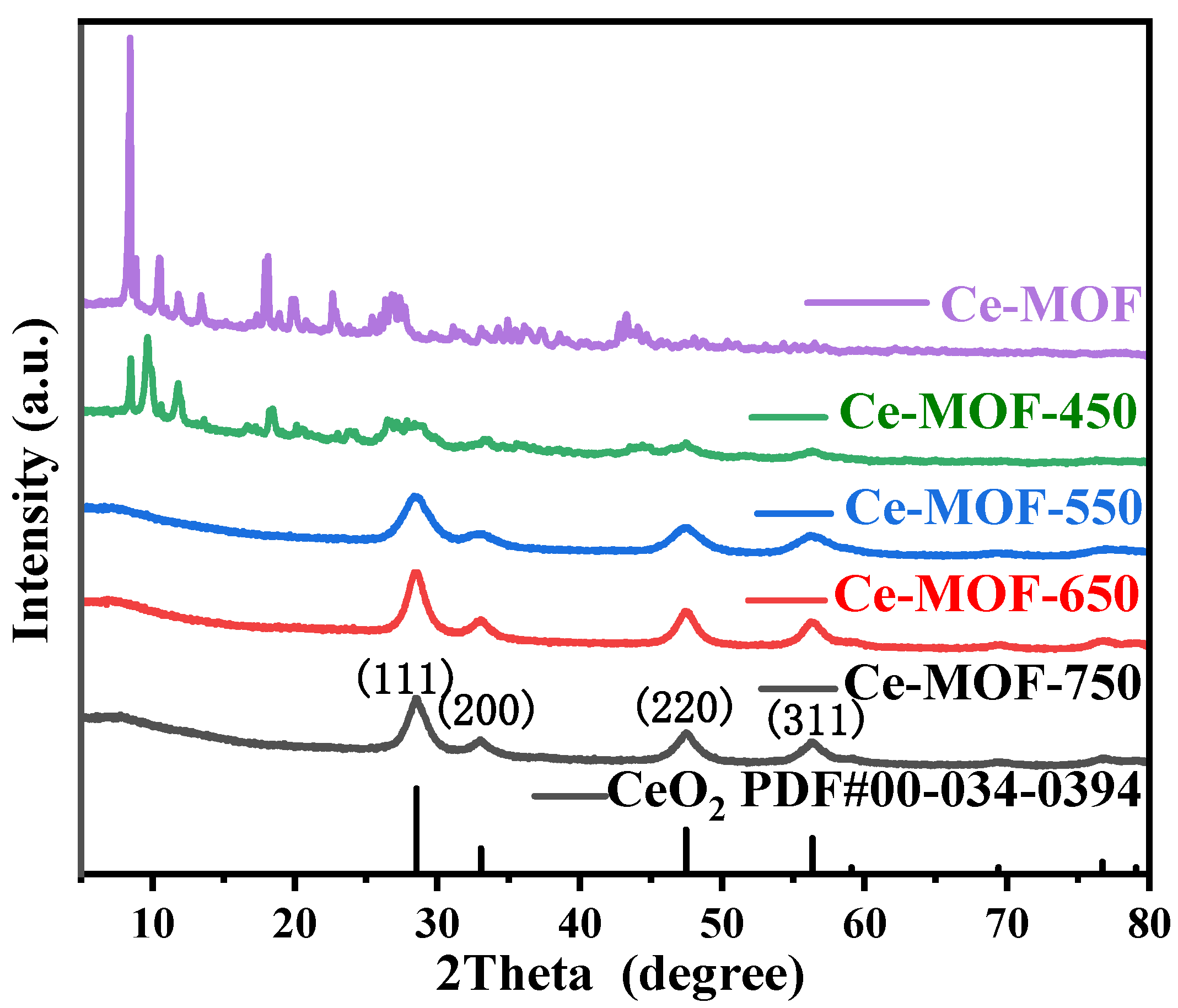
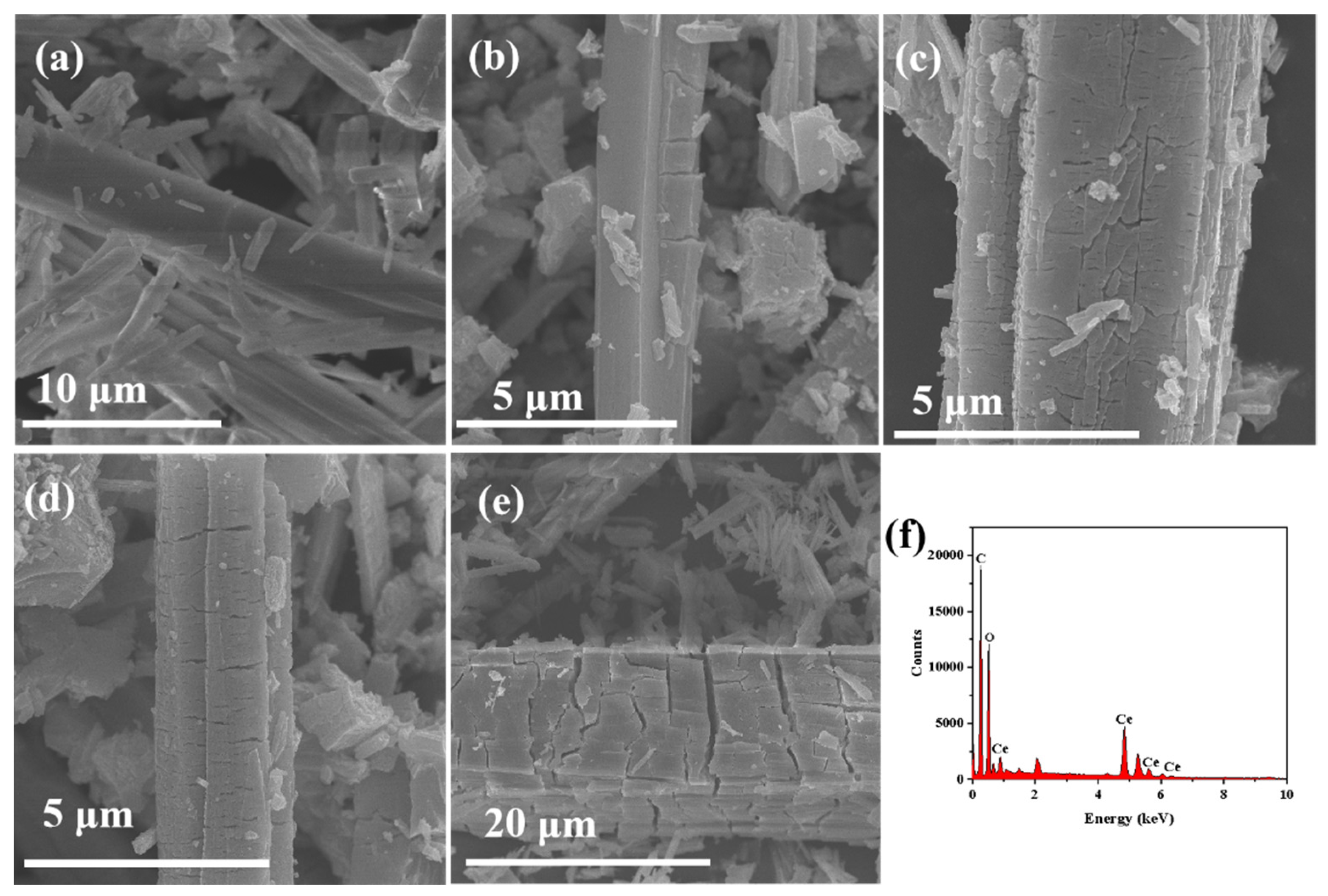
3.1. Structural and Morphological Characterization of Ce-MOF-T

Figure 1 shows the XRD patterns of different Ce-MOF-T samples. It could be seen that the Ce-MOF skeleton gradually collapses with the increase in calcination temperature from the figure. Compared with Ce-MOF, when the calcination temperature reached 550 °C, the diffraction peaks between 10° and 20° in the XRD patterns of the samples disappeared, while apparent diffraction peaks appeared at 28.52°, 33.03°, 47.42°, and 56.33°, corresponding to the (111), (200), (220), and (311) crystal planes of CeO2 based on PDF#00-034-0394, respectively, indicating that Ce-MOF had been pyrolyzed to CeO2. Meanwhile, compared with Ce-MOF-650 and Ce-MOF-750, the diffraction peak width of Ce-MOF-550 was wider, and the crystallinity of the pyrolyzed CeO2 was better. In general, the wider peaks mean more nanocrystals, and more CeO2 nanoparticles can generate more oxygen vacancies with stronger catalytic activity [28].
The Ce-MOF-T after calcination at different temperatures was observed using a scanning electron microscope and the results are shown in Figure 2. From Figure 2a, it can be seen that the uncalcined Ce-MOF was in the form of smooth rods. After calcination, it can be seen that cracks began to appear on the rod-like surface (Figure 2b–e), which was due to the formation of CeO2 grains during the calcination process. With increasing calcination temperature, the cracks in the rod structure became more and more obvious, and when the calcination temperature was 750 °C, the Ce-MOF rod structure was almost broken by the high temperature; at this time, the structure of Ce-MOF was very similar to that of CeO2. Combined with the elemental analysis (Figure 2f), the main elements of Ce-MOF-550 were C, O, and Ce, indicating that the derivatives of Ce-MOF were successfully prepared.
Figure 3 shows the N2 isothermal adsorption and desorption curves of different samples. Before calcination, the specific surface area of Ce-MOF was only 0.42 m2·g−1 (Table 1). Meanwhile, as the calcination temperature increased, the organic ligands were burnt off, the specific surface area and the pore volume increased dramatically, and the specific surface area of Ce-MOF-T increased from 40.72 m2·g−1 (Ce-MOF-450) to 266.58 m2·g−1 (Ce-MOF-550). When the calcination temperature was further increased, the specific surface area of Ce-MOF-650 decreased to 226.83 m2·g−1. This was because the high temperature caused the collapse of the MOF structure, which reduced the specific surface area and led to the reduction in active sites, which was consistent with the SEM results.

3.2. LFX Degradation Study

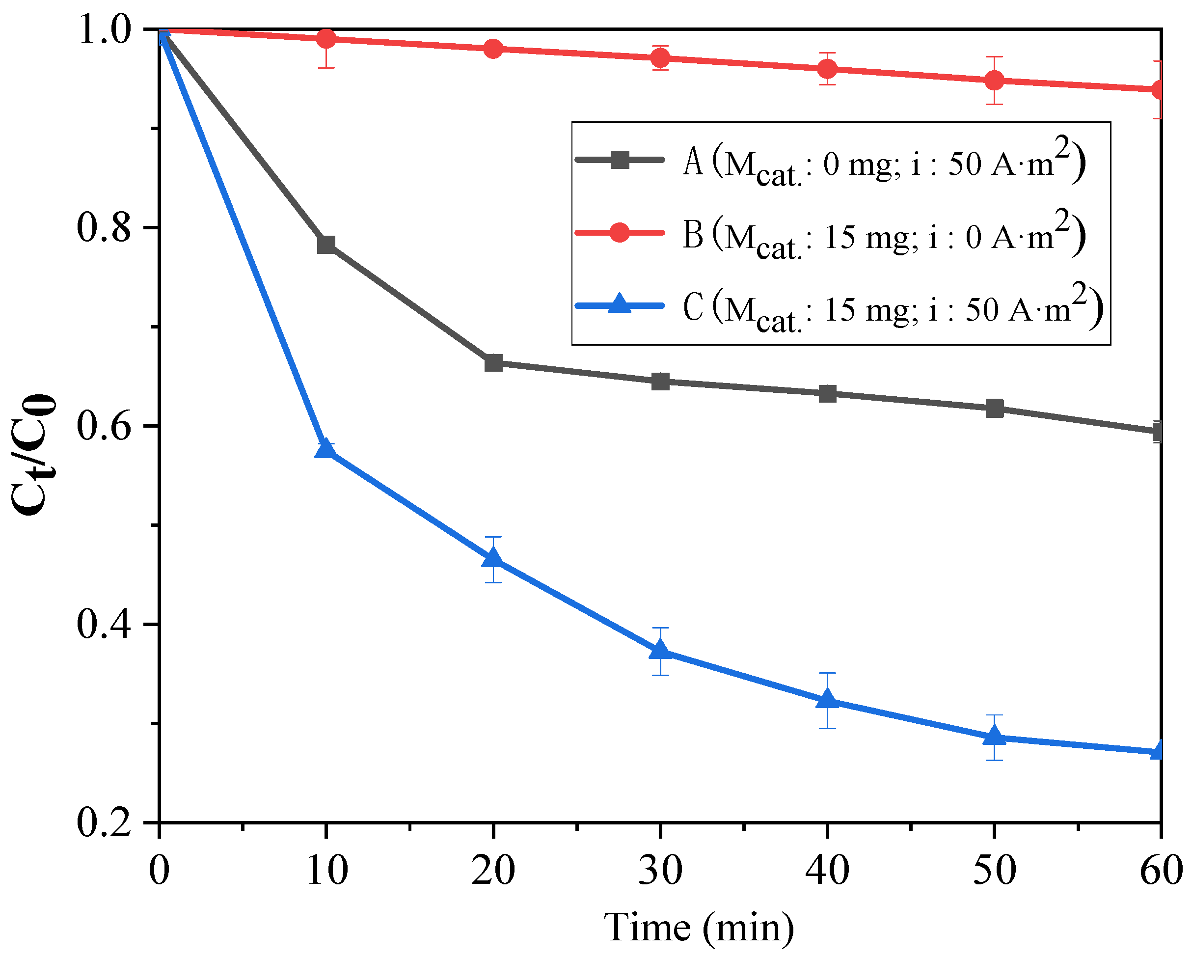
3.2.1. Effect of PMS Activation Mode on the Degradation Rate of LFX

The effect of PMS activation on the degradation rate of LFX using different activation methods is shown in Figure 4 ((A) the loading amount of catalyst (Ce-MOF-550) on the cathode (Mcat.): 0 mg, current density (i): 50 A·m−2; (B) Mcat.: 15 mg, i: 0 A·m−2; (C) Mcat.: 15 mg, i: 50 A·m−2). The degradation was carried out in 20 mg·L−1 of LFX wastewater at an initial concentration (CLFX) of 50 mL with a concentration of PMS (CPMS) of 0.3 g·L−1 and a pH of 5. From the figure, it can be seen that the degradation rate of LFX was only 6.13% when only Ce-MOF-550 catalysis was used, and 40.60% when electroactivation was used. Compared with Ce-MOF-550 catalysis, electroactivation could provide a continuous supply of electrons to activate the PMS to generate sulfate radicals, whereas the conversion of Ce3+ in Ce-MOF-550 to Ce4+ could not be reversibly reduced to Ce3+ by itself. By combining the two activation methods, using Ce-MOF-550-modified carbon cloth as a cathode to degrade LFX by electrolysis, the degradation rate of LFX increased to 72.90% within the same time, which showed a significant improvement, indicating that both of them worked together in activating PMS to degrade LFX. On the one hand, the two different methods could activate PMS, and on the other hand, Ce4+ could be effectively reduced to Ce3+ at the cathode, thus realizing a reversible cycle between low-valence and high-valence Ce states, which could be continuously used for the generation of sulfate radicals to improve the degradation efficiency of LFX.

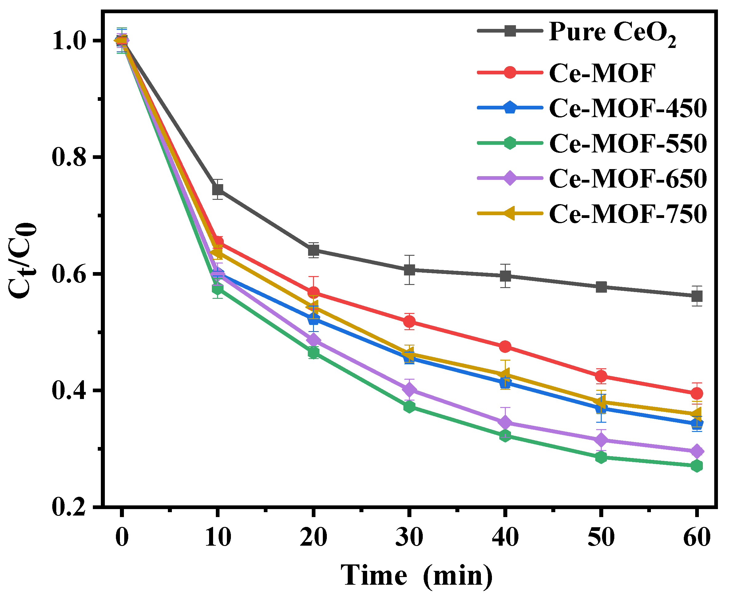
3.2.2. Effect of Calcined Temperature

In order to investigate the effect of Ce-MOF-T/Carbon-C at different calcination temperatures on the degradation of LFX, the degradation was carried out in 20 mg·L−1 of LFX wastewater at an initial concentration of 50 mL with a concentration of Na2S2O8 of 0.3 g·L−1, a pH of 5, a current density of 50 A·m−2, and a loading amount of catalyst on the cathode of 15 mg. As shown in Figure 5, it could be found that the degradation rate of loaded pure cerium oxide was 43.80% after 1 h of reaction, while the degradation rates of Ce-MOF, Ce-MOF-450, Ce-MOF-550, Ce-MOF-650, and Ce-MOF-750 loaded with the same amount were 60.52%, 65.72%, 72.90%, 70.44%, and 64.05% at the same time, which was a significant improvement in the degradation rate. This might be due to the fact that pure CeO2 is mainly Ce4+ with a small specific surface area and few active sites, thus contributing little to degradation, while more Ce3+ was present in Ce-MOF derivatives. Ce3+ could effectively transfer electrons with persulfate to activate it. Among them, Ce-MOF-550 had the highest degradation rate due to its larger specific surface area, which could provide more active sites. Therefore, Ce-MOF-550 was used as the catalyst for subsequent studies.

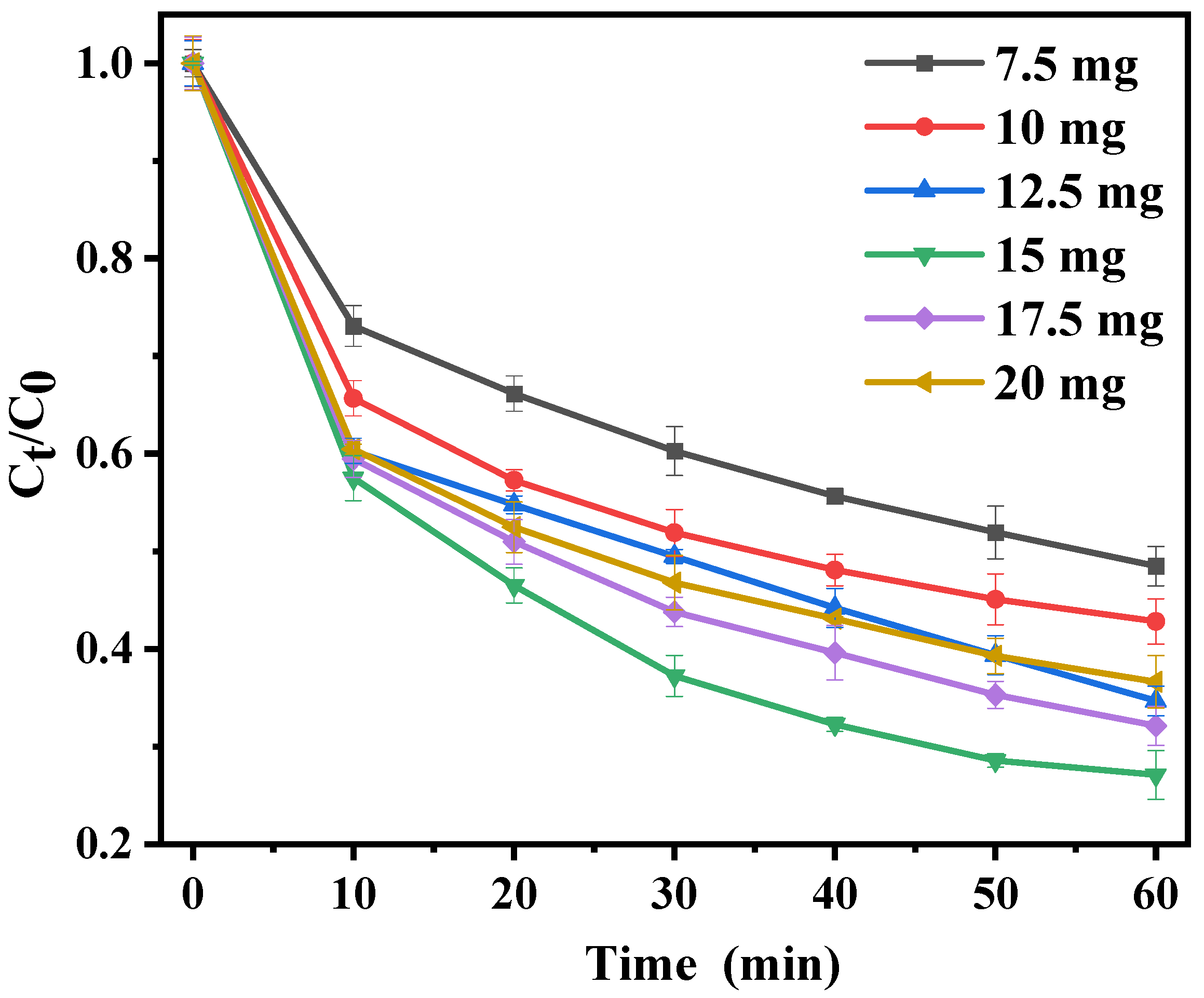
3.2.3. The Effect of Ce-MOF-550 Loading

The effect of Ce-MOF-550 loading on the degradation of LFX wastewater was investigated. The cathodic loadings were 7.5 mg, 10 mg, 12.5 mg, 15 mg, 17.5 mg, and 20 mg, with the results shown in Figure 6. When the loading amount of Ce-MOF-500 was increasing from 7.5 mg to 15 mg, the degradation rate of LFX gradually increased from 51.51% to 72.90%. And when the loading amount was further increased up to 20 mg, the degradation rate of LFX decreased to 63.36%. This may be due to the fact that as the catalyst dosage was increased, the active area of the reaction was increased, which accelerated the electron transfer rate of the sulphate radicals at a given PMS dosage, making the unit LFX molecule more susceptible to degradation by attack by the reactive species. However, if the sulphate radicals were produced too quickly and the concentration in the unit area was too high, the auto-quenching reaction was prone to occur.

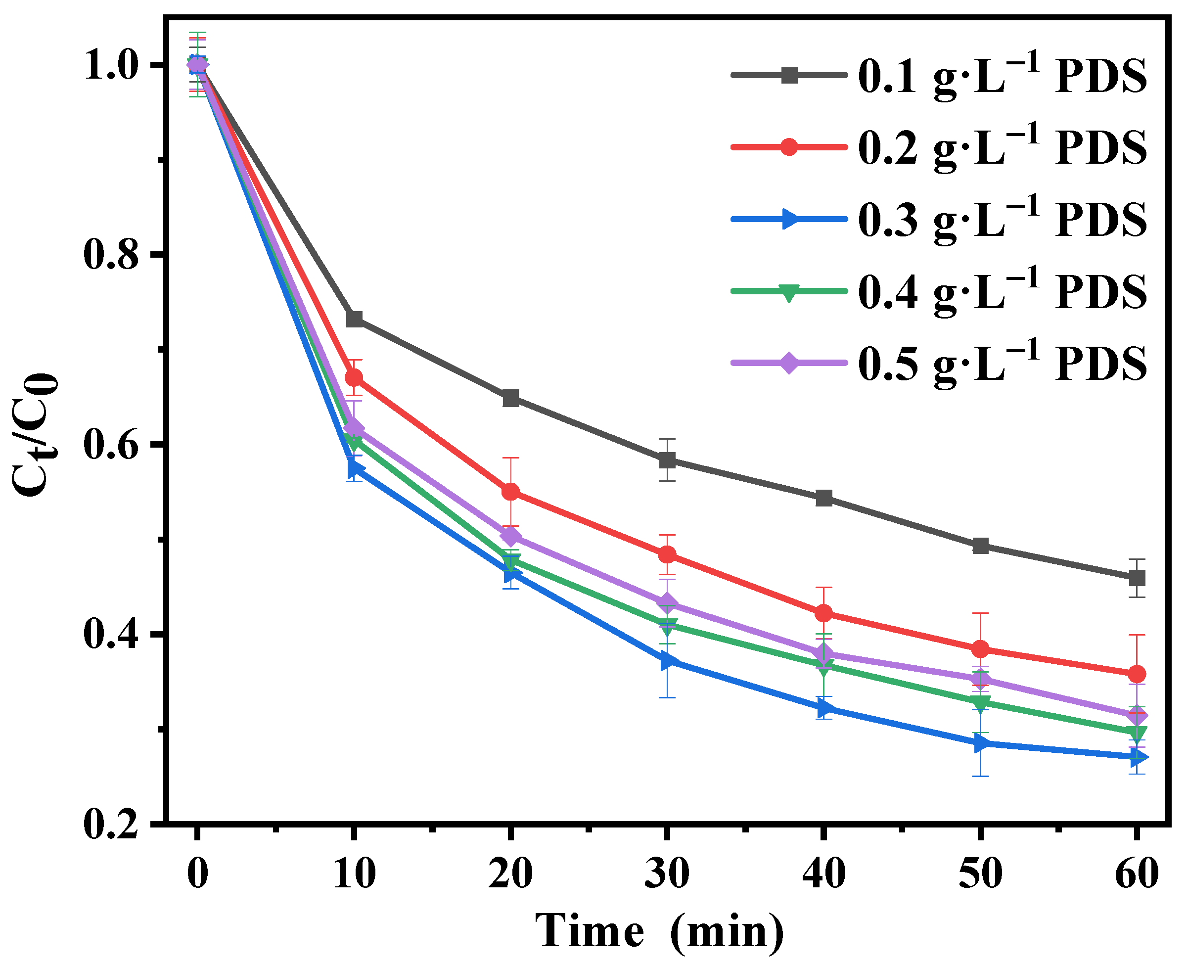
3.2.4. Effect of PMS Concentration
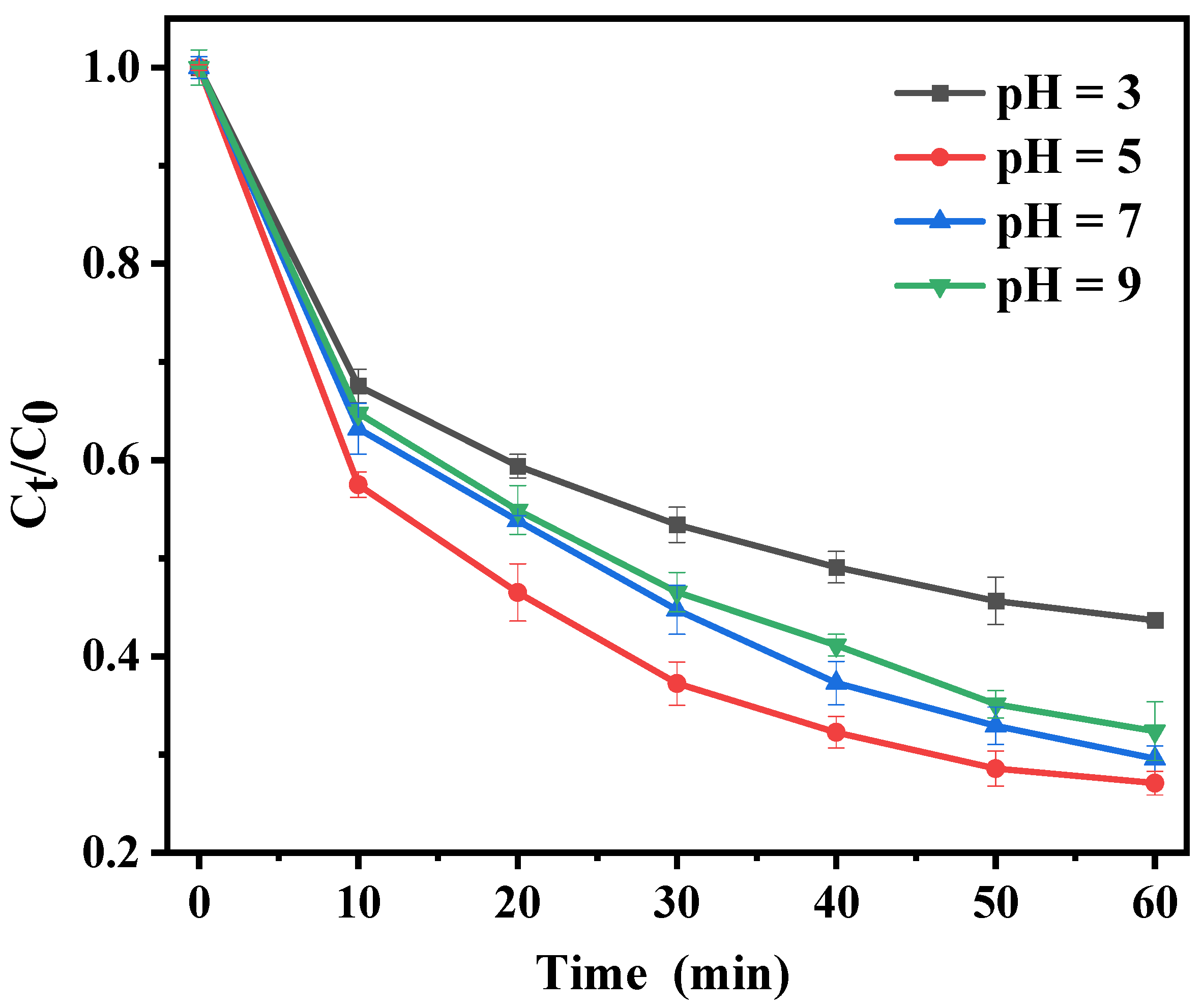
In this experiment, the effect of PMS concentration on the degradation of LFX wastewater was investigated by adding PMS to LFX wastewater at 0.1 g·L−1, 0.2 g·L−1, 0.3 g·L−1, 0.4 g·L−1, and 0.5 g·L−1, and the other conditions were the same as in Section 3.2.1. As shown in Figure 7, when the PMS concentration was increased from the low concentration, the degradation rate of LFX also gradually increased to 54.06% (0.1 g·L−1), 64.17% (0.2 g·L−1), and 72.90% (0.3 g·L−1). But when the PMS concentration was further increased, the degradation rate of LFX started to decrease slightly to 70.32% (0.4 g·L−1) and 68.56% (0.5 g·L−1). With the increase in PMS concentration, the concentration of SO4•− generated by the electroactivation of PMS at the Ce-MOF-derivative-modified cathode increased and the degradation rate of LFX was enhanced. However, if the concentration of PMS was too high, the excess SO4•− might react with itself in a burst reaction or with persulfate, reducing the SO4•− content in the solution and leading to a decrease in the degradation rate of LFX. The reactions were as follows:
2 S O 4 S 2 O 8   2
S O 4 + S 2 O 8 2 S 2 O 8 + S O 4 2

3.2.5. Effect of pH

Figure 8 shows that the initial pH had a significant impact on the degradation rate of LFX. The degradation rates for LFX were 56.33%, 72.90%, 70.44%, and 67.60% at pH values of 3, 5, 7, and 9, respectively. These results indicated that periplasmic PMS could be activated for LFX removal under acidic, neutral, and alkaline conditions. However, when the acidity was too strong, H+ might react with S2O82− to form HSO4. This reaction reduced the concentration of PMS that could be activated, resulting in fewer sulfate radicals being produced. If the alkalinity was too high, OH could react with SO4•− to form •OH, which led to a self-bursting reaction.

3.2.6. Effect of Current Density

Figure 9 shows the degradation rate of LFX effluent at different current densities. The current densities were 20 A·m−2, 40 A·m−2, 50 A·m−2, 75 A·m−2, 100 A·m−2, and 150 A·m−2 and the other conditions were the same as in 3.2.1. It could be seen from the Figure 9 that the degradation rate increased with the increase in current density, which were 52.48%, 69.53%, 72.90%, 79.02%, 82.05%, and 83.40%. This was because the increase in current density accelerated the electron transfer, which facilitated both the direct electron activation of peroxynitrite and the rapid conversion of Ce4+ to Ce3+ for activation of peroxynitrite, resulting in an increase in the rate of sulphate radical production and an increase in the rate of LFX removal. It could be seen that when the current density was low, the degradation rate of LFX increased more markedly as the current density increased, but as the current density increased, the degradation rate of LFX was not very marked, although it did increase. This indicated that when the current density exceeded a certain amount, the main factor affecting the degradation rate of LFX was no longer the current density, but increasing the current would instead increase the electrical energy consumption. Therefore, considering all the factors, it was appropriate to choose a current density of 100 A·m−2 for the actual treatment of wastewater.

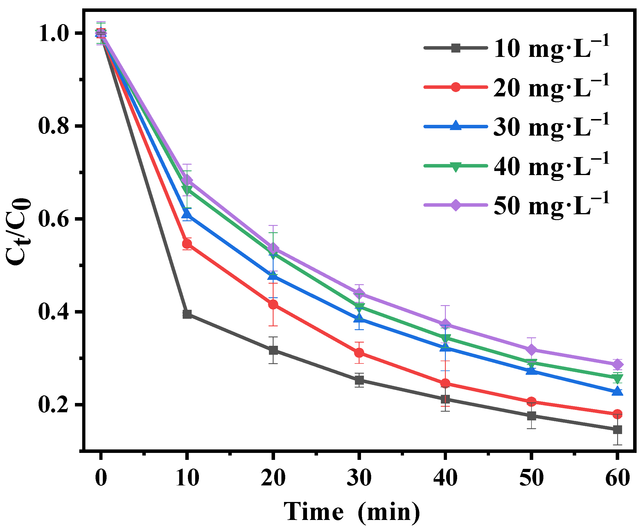
3.2.7. Effect of LFX Concentration

The effect of LFX concentration on its degradation rate was investigated by varying the concentration of LFX to 10 mg·L−1, 20 mg·L−1, 30 mg·L−1, 40 mg·L−1, and 50 mg·L−1, with a current density of 100 A·m−2 and the other conditions as in Section 3.2.1 (Figure 10). After reacting for 1 h, the degradation rates of LFX were 85.34%, 82.05%, 77.28%, 74.20%, and 71.35%, respectively. This indicated that the system had superior degradation performance for LFX at both high and low concentrations. In addition, it could be seen that the degradation rate decreased but the amount of degradation increased with increasing LFX concentration, which suggested that the reaction depended on the rate of generation of sulfate radicals when LFX was high in concentration. Currently, the efficient degradation of high concentrations of LFX could be achieved by adjusting the amount of PMS added and the current density, among other factors.

3.3. Stability Testing

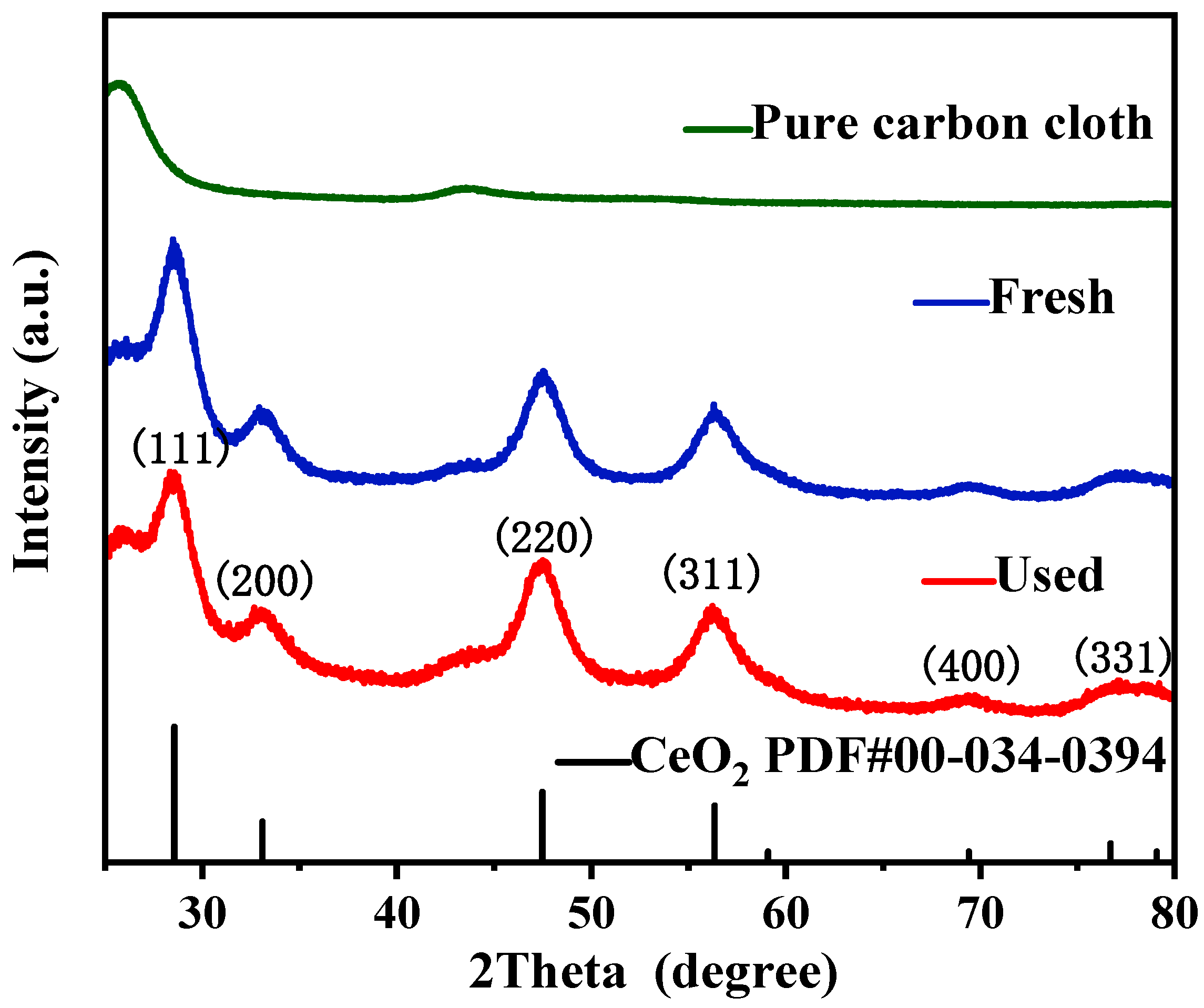
3.3.1. Structural Analysis of Electrode Materials before and after Reaction

The X-ray diffraction analysis of the pure carbon cloth and Ce-MOF-550/Carbon-C before and after the reaction is shown in Figure 11 Compared with the pure carbon cloth, the modified carbon cloth showed carbon peaks at 2θ of 25.66°, while the peaks at 2θ of 28.58°, 33.06°, 47.50°, 56.22°, 69.38°, and 77.08° corresponded to the (111), (200), (220), (311), (400), and (331) crystalline surfaces of CeO2. This indicated that the Ce-MOF-550 catalyst was effectively loaded on the carbon cloth. The XRD peaks of the electrode material before and after the electrolysis reaction were consistent, indicating that the electrode material had no obvious structural changes due to electrolysis. Thus, Ce-MOF-550 had good stability, which could be recycled.

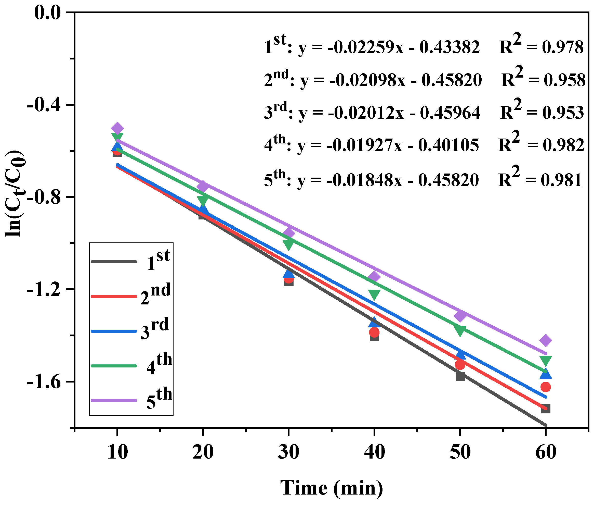
3.3.2. Efficiency of LFX Degradation in Recycling Tests

The stability of electrolysis of the initial Ce-MOF-550-modified carbon cloth was investigated in five cycle experiments. The experimental conditions were as follows: 50 mL of levofloxacin wastewater with an initial concentration of 20 mg·L−1 was degraded, corresponding to the addition of 0.3 g·L−1 of Na2S2O8, a pH of 5, a current density of 100 A·m−2, electrolysis for 1 h, and an initial value of the catalyst loading on the cathode of 15 mg. The carbon cloth electrodes were washed three times in deionized water after each electrolysis and placed in a vacuum oven at 60 °C for 2 h after drying. As shown in Figure 12, the five LFX degradation rates were 82.05%, 80.28%, 79.22%, 77.80%, and 75.86%, with an average degradation rate of 79.04% and a variance of 0.0022, which indicated that Ce-MOF-550/Carbon-C had high stability and the electrolysis process was able to degrade LFX efficiently. The degradation rate constants of LFX during the five cycles are shown in Figure 13. The degradation of LFX was consistent with a quasi-primary kinetic reaction. The apparent rate constants were 2.26 × 10⁻² min−1 (R2 = 0.978), 2.10 × 10⁻² min−1 (R2 = 0.958), 2.01 × 10⁻² min−1 (R2 = 0.953), 2.10 × 10⁻² min−1 (R2 = 0.982), and 2.10 × 10⁻² min−1 (R2 = 0.981), respectively. Through ICP-MS, the cerium ion dissolution was determined and the dissolution rates were only 2.61%, 3.51%, 3.79%, 2.90% and 4.61% for the five cycles, which meant that the concentration of cerium ions in the electrolyte was less than 14 mg/L. The reasons for the decrease in the degradation efficiency were investigated, which may be due to the following: (1) the adsorption of pollutants on the surface of Ce-MOF-550/Carbon-C resulted in a reduction in active sites; (2) some of the organic small molecules were adsorbed on the cathode surface after the degradation reaction occurred on the cathode surface, reducing the catalytic activity; (3) a small number of cerium ions leached out in the course of the reaction; and (4) Ce-MOF-550 became detached due to the washing of the cathode surface during the repetition of the experiments.

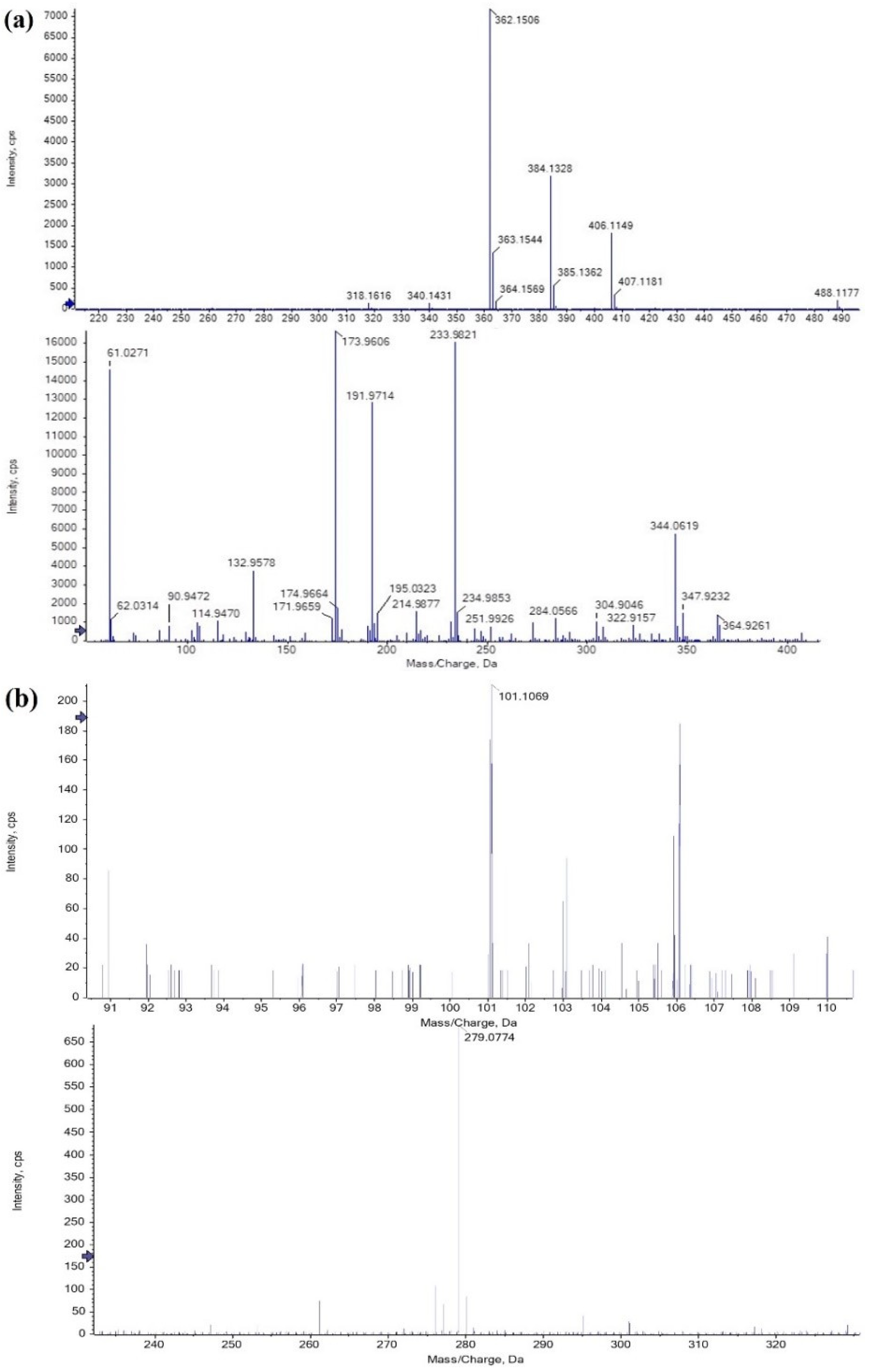
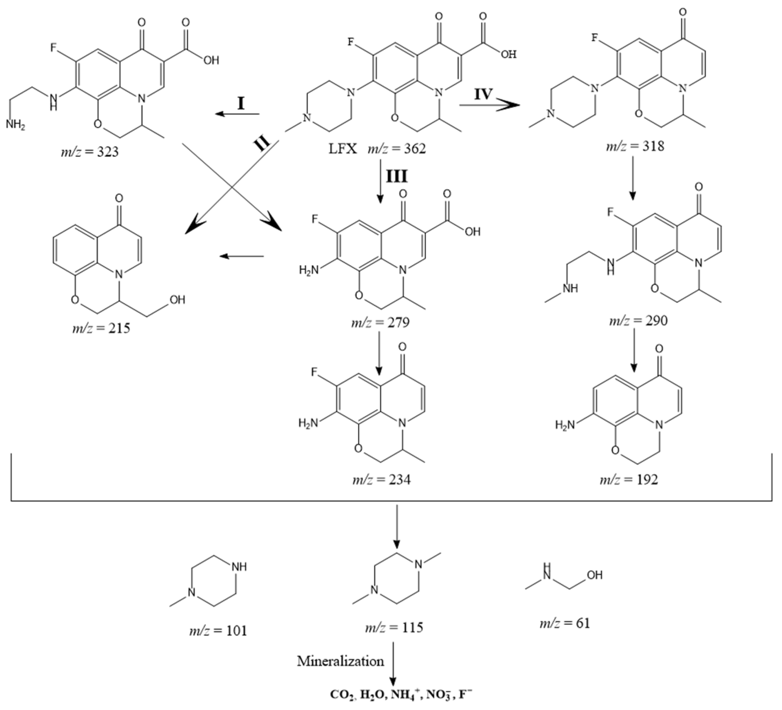
3.3.3. Study of the LFX Degradation Mechanism

In order to speculate on the intermediates and pathways of levofloxacin degradation products, liquid chromatography–mass spectrometry (LC-MS) was used to determine the structure of the intermediates and analyze the possible degradation pathways of LFX. Figure 14a,b show the reaction intermediates. Combined with the relevant literature [29,30,31], the presumed degradation pathway of levofloxacin is shown in Figure 15. In pathway I, the N atom in the piperazine group of LFX is attacked by free radicals, and the N-dealkylation reaction occurs. Pathway II is the hydroxylation of LFX, which breaks the piperazine bond and defluorinates and decarboxylates it. Pathway III is the destruction of the piperazine group to continue decarboxylation and defluorination. Pathway IV is the transformation of LFX into a small-molecule product through decarboxylation, N dealkylation reaction, and defluorination. Finally, LFX is converted to CO2, H2O, NH4+, NO3, and F after mineralization.

4. Conclusions

In conclusion, the prepared Ce-MOF-550 could degrade LFX efficiently by the synergistic activation of PMS with electroactivation. The degradation process was optimized and the preferred conditions were pH = 5, CPMS = 0.3 g·L−1, and i = 100 A·m−2. The degradation rate was 82.05% after 1 h and 95.00% after 3 h of reaction. It was also proven that Ce-MOF-550/Carbon-C had good stability, and the degradation rate was still higher than 79% after 1 h in five consecutive stability tests. The apparent kinetic constants for the degradation of LFX was 2.26 × 10⁻² min−1. In addition, the effect of common ions in LFX wastewater on the degradation system could be further investigated to achieve a universal degradation method and provide a basis for solving the LFX degradation problem.

Author Contributions

Methodology, M.O., W.Z. and S.Y.; software, S.Y.; validation, H.X.; formal analysis, H.X.; investigation, H.X.; data curation W.Z. and S.Y.; writing—original draft preparation, M.O. and W.Z.; writing—review and editing, X.M.; visualization, X.M. and M.O.; supervision, X.M. All authors have read and agreed to the published version of the manuscript.

Funding

This research was funded by [Natural Science Foundation of Zhejiang Province] grant number [No. LY21B030005] and the APC was funded by [Key R&D program of Zhejiang province].

Data Availability Statement

The data presented in this study are available on request from the corresponding author due to privacy.

Acknowledgments

Special thanks to Gao Longqiang, General Manager of Fujian Zhanhua Chemical Limited company for his contribution to the project research Institute in terms of funding, raw materials and formal analysis.

Conflicts of Interest

The authors declare no conflict of interest.

References

  1. Lv, H.; Han, P.; Li, X.; Mu, Z.; Zuo, Y.; Wang, X.; Tan, Y.; He, G.; Jin, H.; Sun, C.; et al. Electrocatalytic Degradation of Levofloxacin, a Typical Antibiotic in Hospital Wastewater. Materials 2021, 14, 6814. [Google Scholar] [CrossRef] [PubMed]
  2. Huang, Z.-H.; Liu, J.-M.; Ji, Z.-Y.; Yuan, P.; Guo, X.-F.; Li, S.-M.; Li, H.; Yuan, J.-S. Effective and continuous degradation of levofloxacin via the graphite felt electrode loaded with Fe3O4. Sep. Purif. Technol. 2022, 281, 119902. [Google Scholar] [CrossRef]
  3. Hamdi El Najjar, N.; Touffet, A.; Deborde, M.; Journel, R.; Leitner, N.K.V. Levofloxacin oxidation by ozone and hydroxyl radicals: Kinetic study, transformation products and toxicity. Chemosphere 2013, 93, 604–611. [Google Scholar] [CrossRef] [PubMed]
  4. An, T.; Yang, H.; Song, W.; Li, G.; Luo, H.; Cooper, W.J. Mechanistic Considerations for the Advanced Oxidation Treatment of Fluoroquinolone Pharmaceutical Compounds using TiO2 Heterogeneous Catalysis. J. Phys. Chem. A 2010, 114, 2569–2575. [Google Scholar] [CrossRef] [PubMed]
  5. Gong, Y.; Li, J.; Zhang, Y.; Zhang, M.; Tian, X.; Wang, A. Partial degradation of levofloxacin for biodegradability improvement by electro-Fenton process using an activated carbon fiber felt cathode. J. Hazard. Mater. 2016, 304, 320–328. [Google Scholar] [CrossRef] [PubMed]
  6. Comninellis, C.; Kapalka, A.; Malato, S.; Parsons, S.A.; Poulios, I.; Mantzavinos, D. Advanced oxidation processes for water treatment: Advances and trends for R&D. J. Chem. Technol. Biotechnol. 2008, 83, 769–776. [Google Scholar]
  7. M’Arimi, M.M.; Mecha, C.A.; Kiprop, A.K.; Ramkat, R. Recent trends in applications of advanced oxidation processes (AOPs) in bioenergy production: Review. Renew. Sustain. Energy Rev. 2020, 121, 109669. [Google Scholar] [CrossRef]
  8. Ike, I.A.; Linden, K.G.; Orbell, J.D.; Duke, M. Critical review of the science and sustainability of persulphate advanced oxidation processes. Chem. Eng. J. 2018, 338, 651–669. [Google Scholar] [CrossRef]
  9. Ding, Y.; Fu, L.; Peng, X.; Lei, M.; Wang, C.; Jiang, J. Copper catalysts for radical and nonradical persulfate based advanced oxidation processes: Certainties and uncertainties. Chem. Eng. J. 2022, 427, 131776. [Google Scholar] [CrossRef]
  10. Wang, S.; Wang, J. Successive non-radical and radical process of peroxymonosulfate-based oxidation using various activation methods for enhancing mineralization of sulfamethoxazole. Chemosphere 2021, 263, 127964. [Google Scholar] [CrossRef]
  11. Huang, S.; Guo, X.; Duan, W.; Cheng, X.; Zhang, X.; Li, Z. Degradation of high molecular weight polyacrylamide by alkali-activated persulfate: Reactivity and potential application in filter cake removal before cementing. J. Pet. Sci. Eng. 2019, 174, 70–79. [Google Scholar] [CrossRef]
  12. Zhang, Z.-w.; Wang, S.; Chen, M.-r.; Bao, N.-n.; Wang, X.-w.; Chen, F.-j.; Ji, G.-j.; Shen, L.; Lu, X.-L.; Song, A.-j. Construction of Fe9S10@Fe2O3@Fe3S4 conductor-semiconductor type heterojunction as photoactivator of peroxymonosulfate toward the degradation of Malachite Green. Chem. Phys. Lett. 2021, 781, 139001. [Google Scholar] [CrossRef]
  13. Hu, C.-Y.; Hou, Y.-Z.; Lin, Y.-L.; Deng, Y.-G.; Hua, S.-J.; Du, Y.-F.; Chen, C.-W.; Wu, C.-H. Investigation of iohexol degradation kinetics by using heat-activated persulfate. Chem. Eng. J. 2020, 379, 122403. [Google Scholar] [CrossRef]
  14. Gu, X.; Lu, S.; Li, L.; Qiu, Z.; Sui, Q.; Lin, K.; Luo, Q. Oxidation of 1,1,1-Trichloroethane Stimulated by Thermally Activated Persulfate. Ind. Eng. Chem. Res. 2011, 50, 11029–11036. [Google Scholar] [CrossRef]
  15. Qu, J.; Liu, R.; Bi, X.; Li, Z.; Li, K.; Hu, Q.; Zhang, X.; Zhang, G.; Ma, S.; Zhang, Y. Remediation of atrazine contaminated soil by microwave activated persulfate system: Performance, mechanism and DFT calculation. J. Clean. Prod. 2023, 399, 136546. [Google Scholar] [CrossRef]
  16. Hu, L.; Zhang, G.; Wang, Q.; Wang, X.; Wang, P. Effect of Microwave Heating on Persulfate Activation for Rapid Degradation and Mineralization of p-Nitrophenol. ACS Sustain. Chem. Eng. 2019, 7, 11662–11671. [Google Scholar] [CrossRef]
  17. García-Cervilla, R.; Santos, A.; Romero, A.; Lorenzo, D. Remediation of soil contaminated by lindane wastes using alkaline activated persulfate: Kinetic model. Chem. Eng. J. 2020, 393, 124646. [Google Scholar] [CrossRef]
  18. Dominguez, C.M.; Rodriguez, V.; Montero, E.; Romero, A.; Santos, A. Abatement of dichloromethane using persulfate activated by alkali: A kinetic study. Sep. Purif. Technol. 2020, 241, 116679. [Google Scholar] [CrossRef]
  19. Gao, F.; Li, Y.; Xiang, B. Degradation of bisphenol A through transition metals activating persulfate process. Ecotoxicol. Environ. Saf. 2018, 158, 239–247. [Google Scholar] [CrossRef]
  20. Anushree, C.; Nanda Gopala Krishna, D.; Philip, J. Efficient Dye Degradation via Catalytic Persulfate Activation using Iron Oxide-Manganese Oxide Core-Shell Particle Doped with Transition Metal Ions. J. Mol. Liq. 2021, 337, 116429. [Google Scholar] [CrossRef]
  21. Liu, J.; Zhong, S.; Song, Y.; Wang, B.; Zhang, F. Degradation of tetracycline hydrochloride by electro-activated persulfate oxidation. J. Electroanal. Chem. 2018, 809, 74–79. [Google Scholar] [CrossRef]
  22. Dhiman, R.; VishnuRadhan, R.; Eldho, T.I.; Inamdar, A. Flood risk and adaptation in Indian coastal cities: Recent scenarios. Appl. Water Sci. 2018, 9, 5. [Google Scholar] [CrossRef]
  23. Adhami, S.; Jamshidi-Zanjani, A.; Darban, A.K. Phenanthrene removal from the contaminated soil using the electrokinetic-Fenton method and persulfate as an oxidizing agent. Chemosphere 2021, 266, 128988. [Google Scholar] [CrossRef] [PubMed]
  24. Pan, X.; Chen, J.; Wu, N.; Qi, Y.; Xu, X.; Ge, J.; Wang, X.; Li, C.; Qu, R.; Sharma, V.K.; et al. Degradation of aqueous 2,4,4′-Trihydroxybenzophenone by persulfate activated with nitrogen doped carbonaceous materials and the formation of dimer products. Water Res. 2018, 143, 176–187. [Google Scholar] [CrossRef] [PubMed]
  25. Jing, B.; Zhou, J.; Li, D.; Ao, Z. Computational study on persulfate activation by two-dimensional carbon materials with various nitrogen proportions for carbamazepine oxidation in wastewater: The essential role of graphitic N atoms. J. Hazard. Mater. 2023, 442, 130074. [Google Scholar] [CrossRef] [PubMed]
  26. Sun, X.; Liu, Z.; Sun, Z. Electro-enhanced degradation of atrazine via Co-Fe oxide modified graphite felt composite cathode for persulfate activation. Chem. Eng. J. 2022, 433, 133789. [Google Scholar] [CrossRef]
  27. Long, Y.; Feng, Y.; Li, X.; Suo, N.; Chen, H.; Wang, Z.; Yu, Y. Removal of diclofenac by three-dimensional electro-Fenton-persulfate (3D electro-Fenton-PS). Chemosphere 2019, 219, 1024–1031. [Google Scholar] [CrossRef] [PubMed]
  28. Zheng, J.; Wang, Z.; Chen, Z.; Zuo, S. Mechanism of CeO2 synthesized by thermal decomposition of Ce-MOF and its performance of benzene catalytic combustion. J. Rare Earths 2021, 39, 790–796. [Google Scholar] [CrossRef]
  29. Gong, S.; Sun, Y.; Zheng, K.; Jiang, G.; Li, L.; Feng, J. Degradation of levofloxacin in aqueous solution by non-thermal plasma combined with Ag3PO4/activated carbon fibers: Mechanism and degradation pathways. Sep. Purif. Technol. 2020, 250, 117264. [Google Scholar] [CrossRef]
  30. Zhong, Y.; Shih, K.; Diao, Z.; Song, G.; Su, M.; Hou, L.; Chen, D.; Kong, L. Peroxymonosulfate activation through LED-induced ZnFe2O4 for levofloxacin degradation. Chem. Eng. J. 2021, 417, 129225. [Google Scholar] [CrossRef]
  31. Wei, S.; Fan, S.; Zhang, M.; Ren, J.; Jia, B.; Wang, Y.; Wu, R.; Fang, Z.; Liang, Q. Dye-sensitized Bi2MoO6 for highly efficient photocatalytic degradation of levofloxacin under LED light irradiation, Mater. Today Sustain. 2023, 21, 100311. [Google Scholar]
Figure 1. XRD patterns of Ce-MOF, Ce-MOF-450, Ce-MOF-550, Ce-MOF-650, and Ce-MOF-750.
Separations 11 00144 g001
Figure 2. SEM spectra of Ce-MOF (a), Ce-MOF-450 (b), Ce-MOF-550 (c), Ce-MOF-650 (d), and Ce-MOF-750 (e) and EDS analysis of Ce-MOF-550 (f).
Separations 11 00144 g002
Figure 3. Nitrogen adsorption–desorption isotherms of Ce-MOF, Ce-MOF-450, Ce-MOF-550, and Ce-MOF-650.
Separations 11 00144 g003
Figure 4. Degradation rate of LFX by different systems (namely, pure electrolysis, pure catalyst, catalyst-combined electrolysis) (CLFX: 20 mg·L−1; CPMS: 0.3 g·L−1; pH: 5; (A) Mcat.: 0 mg, i: 50 A·m−2; (B) Mcat.: 15 mg, i: 0 A·m−2; (C) Mcat.: 15 mg, i: 50 A·m−2).
Separations 11 00144 g004
Figure 5. Effect of Ce-MOF derivatives on degradation rate after calcination at different temperatures. (CLFX: 20 mg·L−1; CPMS: 0.3 g·L−1; pH: 5; i: 50 A·m−2; Mcat.: 15 mg).
Separations 11 00144 g005
Figure 6. Effect of loading on degradation rate. (CLFX: 20 mg·L−1; CPMS: 0.3 g·L−1; pH: 5; i: 50 A·m−2; Mcat.: 7.5, 10, 12.5, 15, 17.5, 20 mg).
Separations 11 00144 g006
Figure 7. Effect of PMS concentration on degradation rate. (CLFX: 20 mg·L−1; CPMS: 0.1, 0.2, 0.3, 0.4, 0.5 g·L−1; pH: 5; i: 50 A·m−2; Mcat.: 15 mg).
Separations 11 00144 g007
Figure 8. Effect of pH on degradation rate. (CLFX: 20 mg·L−1; CPMS: 0.3 g·L−1; i: 50 A·m−2; Mcat.: 15 mg).
Separations 11 00144 g008
Figure 9. Effects of different current densities on degradation rate. (CLFX: 20 mg·L−1; CPMS: 0.3 g·L−1; pH: 5; Mcat.: 15 mg).
Separations 11 00144 g009
Figure 10. Effect of LFX concentration on degradation rate. (CPMS: 0.3 g·L−1; pH: 5; i: 100 A·m−2; Mcat.: 15 mg).
Separations 11 00144 g010
Figure 11. XRD patterns of pure carbon cloth, unused Ce-MOF-550, and used Ce-MOF-550.
Separations 11 00144 g011
Figure 12. Effect of C recycling on degradation rate. (CLFX: 20 mg·L−1; CPMS: 0.3 g·L−1; pH: 5; i: 100 A·m−2; Mcat.: 15 mg).
Separations 11 00144 g012
Figure 13. Degradation rate constants of LFX. (CLFX: 20 mg·L−1; CPMS: 0.3 g·L−1; pH: 5; i: 100 A·m−2; Mcat.: 15 mg).
Separations 11 00144 g013
Figure 14. (a,b) The intermediate products of the reaction.
Separations 11 00144 g014
Figure 15. The degradation process of LFX.
Separations 11 00144 g015
Table 1. BET surface area, pore volume, and pore size of different samples.
SamplesBET Surface Area (m2g−1)Pore Volume (cm3g−1)Pore Size (nm)
Ce-MOF4.700.003432.8459
Ce-MOF-45040.720.07237.1008
Ce-MOF-550266.580.34295.1457
Ce-MOF-650226.830.33975.9909
Disclaimer/Publisher’s Note: The statements, opinions and data contained in all publications are solely those of the individual author(s) and contributor(s) and not of MDPI and/or the editor(s). MDPI and/or the editor(s) disclaim responsibility for any injury to people or property resulting from any ideas, methods, instructions or products referred to in the content.

