Article

Optimizing Membrane Distillation Performance through Flow Channel Modification with Baffles: Experimental and Computational Study

School of Energy and Power Engineering, Dalian University of Technology, No. 2 Linggong Road, Dalian 116024, China
*
Author to whom correspondence should be addressed.
Separations 2023, 10(9), 485; https://doi.org/10.3390/separations10090485
Submission received: 10 August 2023 / Revised: 31 August 2023 / Accepted: 2 September 2023 / Published: 5 September 2023
(This article belongs to the Special Issue Modeling, Simulation, and Optimization of Membrane Processes)

Abstract

:
It has been identified that temperature polarization and concentration polarization are typical near-surface phenomena limiting the performance of membrane distillation. The module design should allow for effective flow, reducing the polarization effects near the membrane surfaces and avoiding high hydrostatic pressure drops across and along the membrane surfaces. A potential route to enhancing the membrane distillation performance is geometry modification on the flow channel by employing baffles as vortex generators, reducing the polarization effects. In this work, various baffles with different structures were fabricated by 3D printing and attached to the feed flow channel shell in an air gap membrane distillation module. The hydrodynamic characteristics of the modified flow channels were systematically investigated via computational fluid dynamics simulations with various conditions. The membrane distillation tests show that adding the baffles to the feed channel can effectively increase the transmembrane flux. The transmembrane flux with rectangular baffles and shield-shaped baffles increases by 21.8% and 28.1% at the feed temperature of 70 °C. Moreover, the shield-shaped baffles in the flow channel not only enhance the transmembrane flux but also maintain a low-pressure drop, making it even more significant.

1. Introduction

Membrane distillation (MD) is a thermally driven separation process based on a temperature gradient across a porous membrane as a barrier [1,2]. In an MD process, the liquid phase fluid and gas phase fluid flow along the membrane surface and across the membrane surface, respectively. The membrane surface acts as both a fluid dynamics boundary and molecular diffusion entrance [3]. It is important to investigate the near-surface behaviors because of the strong correspondence to MD performance in terms of permeate flux and energy efficiency.
The temperature near the membrane surface is lower than the bulk feed temperature due to the imperfect thermal insulating membrane barrier and the vaporization latent heat consumption [4,5]. The effective temperature gradient across the porous membrane is lower than that between the bulk solutions, thereby reducing the driving force for MD. The loss of driving force caused by thermal gradients in the feed near the membrane is known as temperature polarization [6]. During the MD process, water evaporation on the membrane surface leads to solute of feed continuously accumulating near it. The concentration of feed near the porous membrane is larger than that of the bulk, which leads to the formation of concentration polarization [7]. Temperature and concentration polarizations significantly affect the MD performance, e.g., transmembrane flux [8,9,10] and system energy efficiency [11,12].
Some researchers have mentioned that optimizing the operational parameters and the module dimensions can reduce the temperature and concentration polarization phenomena. It is possible to reduce temperature and concentration polarizations by using novel porous membranes in the MD module [9]. Coating polymeric membranes with a carbon-based nanotube layer or with photonic nanomaterials can overcome the temperature polarization and thermal boundary layer effects [13,14,15]. The self-heated porous membrane could directly heat the feed near the membrane by photothermal heating (solar) and also can lower temperature polarization [16,17,18]. Adding corrugations or other micromixers on the membrane surface to act as turbulence promoters could also reduce the polarization phenomenon [19,20,21].
Another route to mitigating the polarization effects is increasing the chaotic state of the flow near the membrane surface, such as increasing the feed velocity and using pulse flow [22,23] or filling the spacers in the flow channels [24,25,26,27]. It has been reported that changing the geometry of the MD module channel is an effective approach to increasing the chaotic state of feed and coolant [28,29,30,31]. Kuang et al. have researched the potential of adding baffles on flow channels to enhance direct contact membrane distillation (DCMD) performance [32]. The results revealed that the structural modification of the DCMD flow channels could eliminate the temperature polarization and concentration polarization, thus improving the MD transmembrane flux. It has also been mentioned that adding baffles or filling the spacers in the flow channels also contributes to the extra power consumption of the MD system [24,25,26,27,32].
For the conventional MD configurations, the air gap membrane distillation (AGMD) has a condensing surface on the permeate side, which is separated from the membrane surface by the air. Compared to the DCMD configuration, the air gap of the AGMD configuration leads to it having a higher thermal efficiency. AGMD configuration is less complex compared with the sweep gas membrane distillation and vacuum membrane distillation, in which an external condenser must be employed to obtain permeate water.
In this work, geometry modification of the AGMD flow channels (the feed channels) was applied to reduce the polarization effects and enhance the MD performance without increasing the power consumption of the system too much. Various baffles with different geometric structures were fabricated by 3D printing. They were installed in the flow channel to generate turbulence and vortex near the membrane surface and along the flow direction. The computational fluid dynamics (CFD) simulations were used to investigate the hydrodynamic characteristics of the modified flow channels (e.g., velocity, pressure drop, and wall shear stress). The effects of baffle characteristics on the MD performance were verified with related experiments. The MD tests show that adding the baffles to the feed channel can significantly increase the transmembrane flux. Modifying the flow channel with the shield-shaped baffles can improve the MD performance without increasing the pressure drop.

2. Experimental Section

2.1. Membrane Distillation Module

Figure 1a shows the AGMD module used in this work. The flow channels, sealing gaskets, and membrane sheets were assembled using 14 Allen screw bolts and nuts. Both the feed channel and coolant channel were made of polymethyl methacrylate (PMMA). The feed and coolant were the co-current flow style. The tilt angle between the module and the horizontal line was kept at 5 ± 1° so that the permeate could flow out from the air gap in time. The flow channels were 450 mm × 30 mm × 20 mm (length, width, and height). The air gap thickness was 2 mm, which was filled with a polyethylene (PE) mesh spacer. To make the membrane maintained flat, a piece of stainless steel spacer with a woven structure (thickness of ~0.5 mm, void of 1 mm × 1 mm) was sandwiched between the porous membrane and the PE spacer. The effective area of the porous membrane was 110 cm2. The silica gel frames were used as the sealing gaskets (thickness of 2 mm). The condensing plate was an aluminum alloy plate (thickness of 0.5 mm).

2.2. Porous Membranes

The porous membranes used in this study were commercial hydrophobic polytetrafluoroethylene (PTFE) obtained from Membrane Solutions, LLC (Shanghai, China). The surface morphology of the porous membrane was characterized by scanning electron microscopy (SEM), and the SEM image is shown in Figure 1a. The membrane nominal pore size provided by the manufacturer was 0.22 μm. The porosity was 75 ± 5% (provided by the manufacturer). The hydrophobicity of the porous membrane was characterized by the static water contact angle (153 ± 5°) that was measured with a goniometer. A custom-design unit was used to measure the membrane’s liquid entry pressure. A syringe pump at the speed of 0.5 mL/min was used to provide pressure on the membranes. A piezometer connected to the chamber detected the liquid pressure on the membrane. The pressure data were recorded each second by the computer. The LEP of the membrane was 600 ± 50 kPa. The thickness of the membrane measured by a micrometer was 40 ± 5 μm. The specific information about these devices can be found in our previous work [33].

2.3. Preparation of the Baffles in the Flow Channels

The baffles were fabricated by 3D printing because it can quickly and inexpensively complete complex manufacturing [34]. The baffles were attached to the flow channel of the MD module; they needed to keep the stability of the geometry structure at about 80 °C. Therefore, the baffles were made of nylon (as shown in Figure 1c). One surface of the baffles was flat so that it could be attached to the flow channel shell. The width of the baffles was 29.6 ± 0.1 mm, which was smaller than the flow channel. The length of the rectangular baffle, arc-shaped baffle, and shield-shaped baffle was 10 mm, 60 mm, and 45 mm. The height of the rectangular baffle was between 4 mm and 16 mm. The curve equation for an arc-shaped baffle was a cubic polynomial ( y = 2.4 0.63 x + 0.013 x 2 0.0000351 x 3 ). The curve of the shield-shaped baffle was first a circular arc with a radius of 10 mm and then the same as that of an arc-shaped baffle. The maximum dimension of the arc-shaped baffle and shield-shaped baffle in height was 10 mm. The baffles were arranged along the flow direction with a step distance of 60 mm.

2.4. AGMD Tests

The lab-scale experimental setup included the AGMD module, feed pump, coolant pump, feed tank, coolant tank, thermocouples, computer (to record data), digital balance, and connection pipes (as shown in Figure 1a,b). Feed and coolant pumps provided power to circulate the feed (3.5 wt% NaCl solution) and coolant (water). The feed temperatures increased by increments of 5 °C, varied from 50 to 70 °C. The feed flow rate was measured by a rotameter, maintained at 0.8 L/min. The coolant temperature was 20 ± 2 °C. The transmembrane flux was measured by the weight of the distillation using a digital balance. The data were recorded every 60 s using a computer. The feed pump, coolant pump, rotameter, and digital balance in the MD system were described in detail in our previous work [3].
Before data recording for each transmembrane flux test, we ran the experimental setup for 0.5 h to remove dissolved gases from the feed. After running for 0.5 h, the experimental setup could also reach a steady state, and the transmembrane flux could be recorded. For each selected feed temperature, the test was maintained for one hour. The value of transmembrane flux was the average value over one hour tested. The experiment with a flat channel was carried out first. Then, the baffles were attached to the flow channel to complete the other tests.

3. CFD Simulations

3.1. Geometry Model

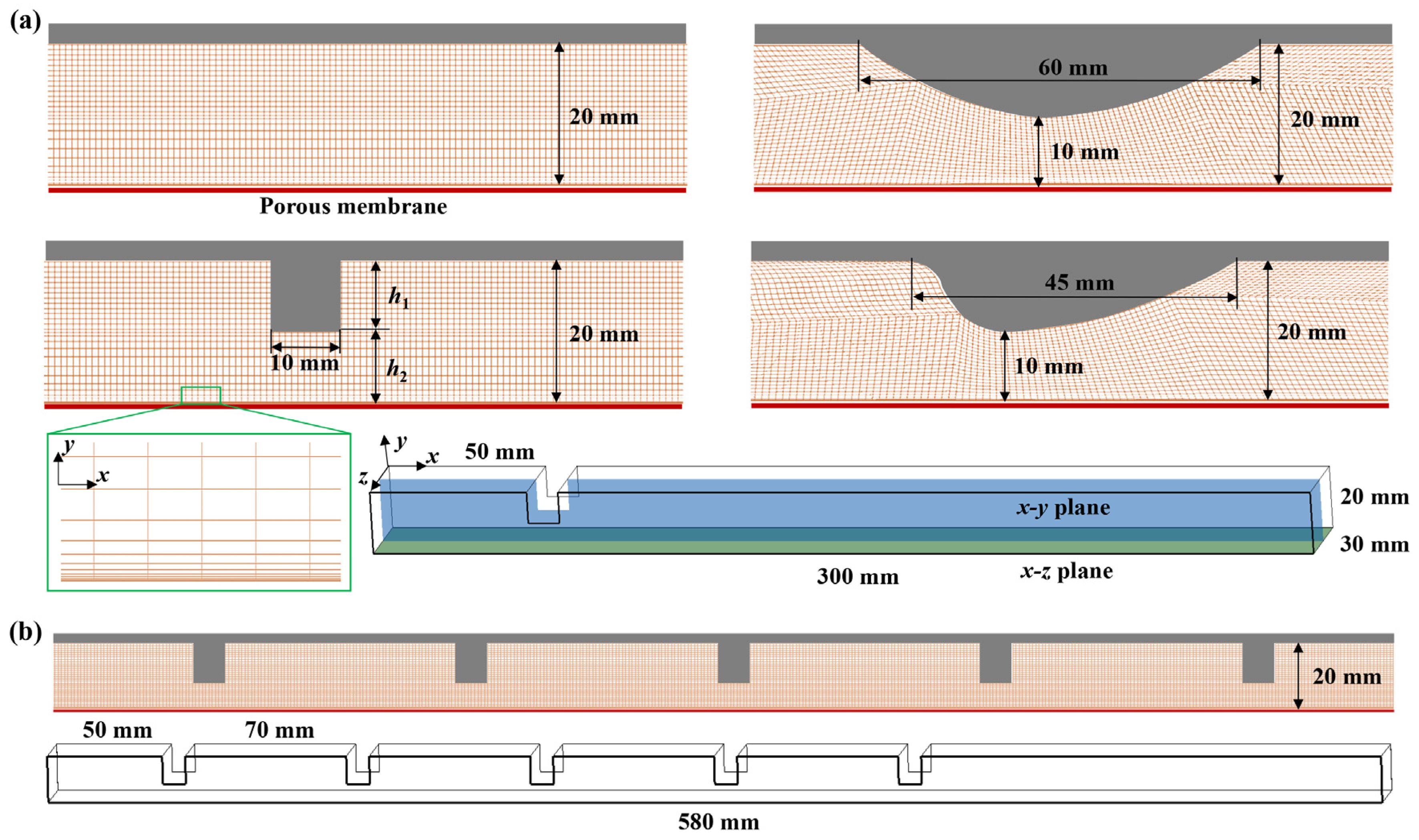
The feed in the flow channels was defined as fluid bodies. As shown in Figure 2, the three-dimensional (3D) geometrical models were introduced to study the hydrodynamic behavior of the flow state in the flow channels. The computational domain only included the fluid region. When there was one baffle or no baffle, the length of the computational domain was 300 mm (see Figure 2a). The length of the computational domain was 580 mm when adding five baffles to the flow channel (see Figure 2b). The height and width of the computational domain were 20 mm and 30 mm, respectively. The first baffle was set at 50 mm from the inlet surface. The distance between two adjacent baffles was 70 mm. The xy plane is a z-normal plane through the center of the computational domain. The xz plane is the bottom surface of the computational domain, which is also the membrane’s high-temperature surface.

3.2. Mesh Generation

The meshes of the simulated geometry were built using the meshing software Ansys ICEM 18.0. Since the geometric structure of the computational domain is simple, the computational domain was discretized by finite hexahedra grids. To save the cost of the calculation and optimize the results, the grids near the bottom surface were densified. The first layer of the grids in the y direction was 1 × 10⁻⁵ m and progressively increased with a ratio of 1.5 from 1 × 10⁻⁵ m to 1 × 10⁻³ m. The grids in the x and z directions were 1 × 10⁻³ m uniformly. Figure 2a shows some details of the computational domain.
Increasing the number of grids in the y direction to complete the grid independence analysis. Table 1 shows the mesh dependence test results. The number of cells selected in this work was 560,000 (case 2).
In Table 1, ui was inlet velocity. ΔP was the pressure difference between two boundary surfaces. L (L = 300 mm) was the length of the computational domain. Re (Reynolds number) was defined as follows:
Re = ρ u a v d h μ
d h = 2 W H W + H
In Equation (1), ρ is density; μ is dynamic viscosity; dh is hydraulic diameter, and uav is mean velocity. In Equation (2), W and H are the width and height of the flow channel, respectively.

3.3. Assumptions and Governing Equations

Some simplifying assumptions were considered for the CFD simulations as follows: (i) the feed was water–liquid; (ii) non-slip walls; (iii) atmospheric pressure in the outlet; (iv) negligible the influence of the gravity.
Because the CFD simulations were only used to investigate the hydrodynamic characteristics of the modified flow channels, the heat transfer process of the module and the mass transfer across the membrane were not considered. For the incompressible flow process without heat transfer, the equations of continuity and momentum conservation are as follows:
ρ u x + ρ v y + ρ w z = 0
u u x + v u y + w u z = 1 ρ P x + υ ( 2 u x 2 + 2 u y 2 + 2 u z 2 )
u v x + v v y + w v z = 1 ρ P y + υ ( 2 v x 2 + 2 v y 2 + 2 v z 2 ) + ρ g
u w x + v w y + w w z = 1 ρ P z + υ ( 2 w x 2 + 2 w y 2 + 2 w z 2 )
where u, v, and w are the velocity components; υ is the kinematic viscosity; ρ is the density; P is the pressure. The physical properties of the fluid are listed in Table 2.

3.4. Boundary Conditions

For the numerical simulation, the feed was assumed to be water–liquid. The boundary condition of the inlet surface was velocity inlet, which was normal to the inlet surface. The boundary condition of the outlet surface was pressure outlet (0.0 Pa, gauge pressure) [35]. The other walls of the computational domain were set to be adiabatic and no-slip conditions.

3.5. Algorithm and Turbulence Model

In this work, the mass and heat transfer of the AGMD was not considered. Numerical solutions were carried out with the commercial software Ansys Fluent 18.0. The pressure–velocity coupling was solved by the SIMPLE algorithm. The discretization of the differential equations was solved by a second-order upwind algorithm. Depending on the case simulated, different numbers of iterations were performed until all the residuals were lower than 1 × 10⁻⁵. To accurately characterize the flow state near the membrane surface, SST k-ω was employed [21].

4. Results and Discussion

4.1. Flow Disturbance near Membrane Surface by Baffles in the Flow Channel

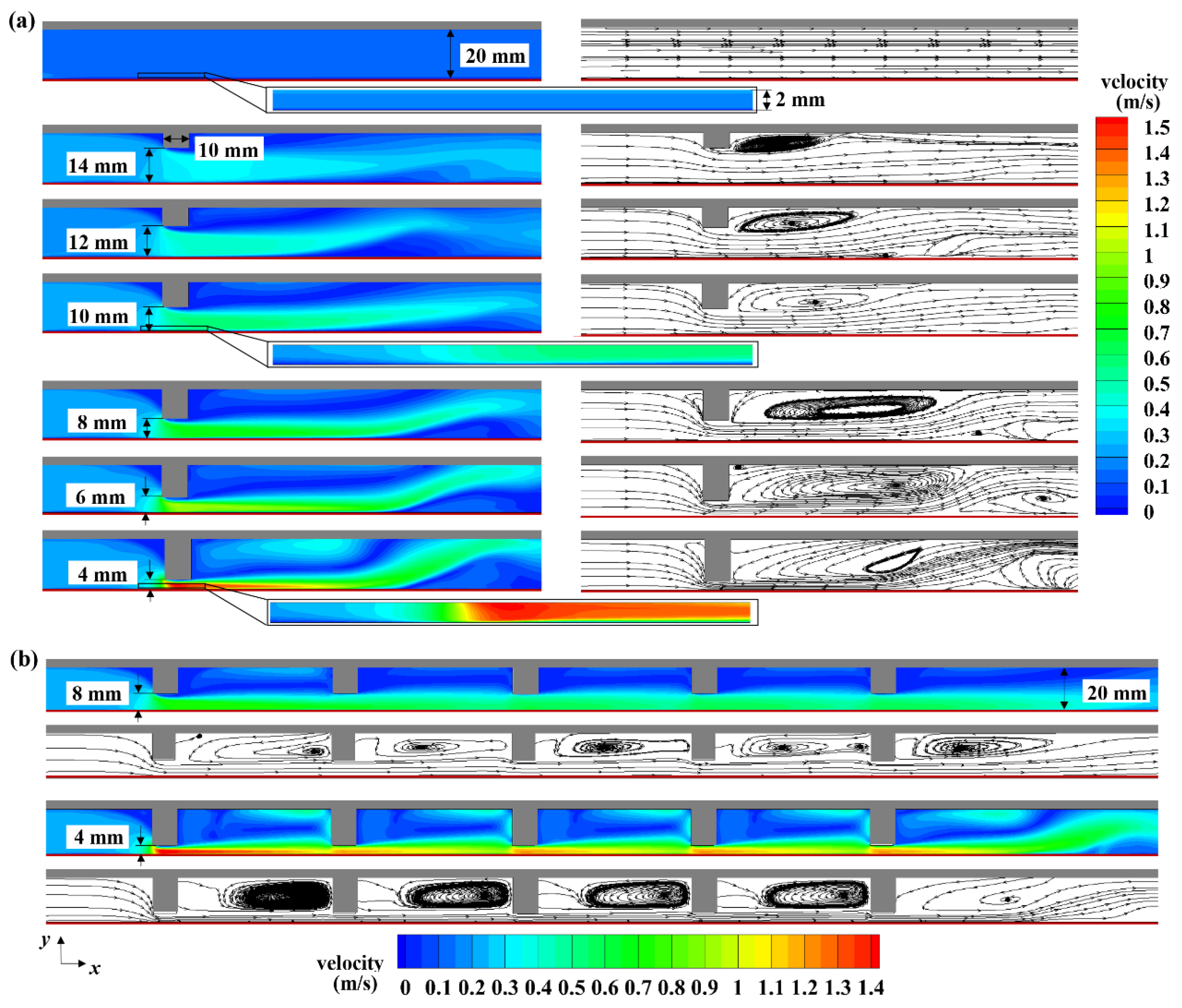
Figure 3a presents the local velocity contours and streamlines for the xy plane. The velocity at the inlet is set as 0.2 m/s. The rectangular baffles have various heights, leading to different sizes of gaps between the baffles and the membrane. For the flat channel, the velocity of the main flow stream is the same as that at the inlet, which is 0.2 m/s. The existence of the velocity boundary layer due to feed viscosity leads to a dragging effect on the flow near the membrane surface (2 mm above the membrane surface). It can be observed that all the streamlines are along the flow direction in the flat channel.
The rectangular baffle in the flow channel will decrease its cross-sectional area, which leads to the velocity near the baffle edge being larger than the inlet velocity. The velocity above the membrane surface increases with the decrease in the gaps between the baffles and the membrane. The velocity near the membrane surface of the flat channel is about 0.1–0.2 m/s. When the size of the gap between the baffle and the membrane is 10 mm, the velocity near the membrane surface is about 0.5–0.6 m/s. Decreasing the size of the gap between the baffle and the membrane to 4 mm, the flow velocity near the membrane surface can be increased to about 1.5 m/s. The velocity boundary layer still exists above the membrane surface with the existence of the baffle, but its thickness is significantly smaller than that in the flat flow channel.
The flow has been fully developed before reaching the baffle. After the flow reaches the baffle, the boundary layer separation occurs in the downstream zone of the baffle due to the area change in the flow channel, thus forming a recirculating zone in the flow channel (as shown in the streamline diagram in Figure 3a). With the decrease in the gap between the baffle and membrane, the area of the recirculation zone increases, and the distance between the attachment point and the baffle also increases. When the gap between the baffle and the membrane is larger than 10 mm, only one recirculating zone is formed (near the flow channel shell). Increasing the height of the baffle to make the gap between the baffle and the membrane smaller than 10 mm, another recirculation zone is formed near the membrane surface. With baffle used, the flow is significantly affected by the longitudinal vortex. The vortex will bring the bulk fluid (feed with higher temperature and lower concentration) into the zone near the membrane surface. Thus, the thermal and concentration boundary layer is thinner than those in the flow channel without baffle [31].

4.2. Influence of Multiple Baffles in the Flow Channel

The results of Section 4.1 show that adding a rectangular baffle in the flow channel can reduce velocity boundary layer thickness by increasing flow velocity near the membrane surface. The vortex formed in the downstream region of the baffle can bring the bulk fluid into the near membrane surface zone. Thus, the effect of polarization on MD performance can be mitigated. If only one baffle is attached to the flow channel, the flow will gradually return to the fully developed flow state after passing through the baffle, and the flow boundary layer will form on the membrane surface again. Therefore, multiple baffles should be added to the flow channel to continuously destroy the flow boundary layer.
Figure 3b shows the local velocity contours and streamlines of the xy plane when five rectangular baffles are attached to the flow channel. The flow velocity above the membrane surface increases significantly after adding multiple baffles in the flow channel. There is the largest flow velocity near the first baffle. A recirculating zone is formed between two rectangular baffles. The recirculating zone is near the flow channel shell (see the streamlines in Figure 3b). The smaller the gap between the baffles and the membrane, the larger the recirculating zone area. Decreasing the gap between the baffles and the membrane can improve the velocity above the membrane surface to mitigate the influence of polarization on MD performance. If the gap between the baffles and the membrane is too small, the feed in the recirculating zone cannot circulate well with other feed. The feed temperature in this part may be lower than the feed inlet temperature, thus reducing the MD transmembrane flux.

4.3. Influence of Baffle Geometry

Attaching multiple rectangular baffles to the flow channel will form a vortex between two rectangular baffles. The existence of the vortex will consume energy, thereby increasing the power consumption of the MD system. This section will further optimize the flow state by tuning the geometric structures of the baffles.

4.3.1. Velocity in the Flow Channel

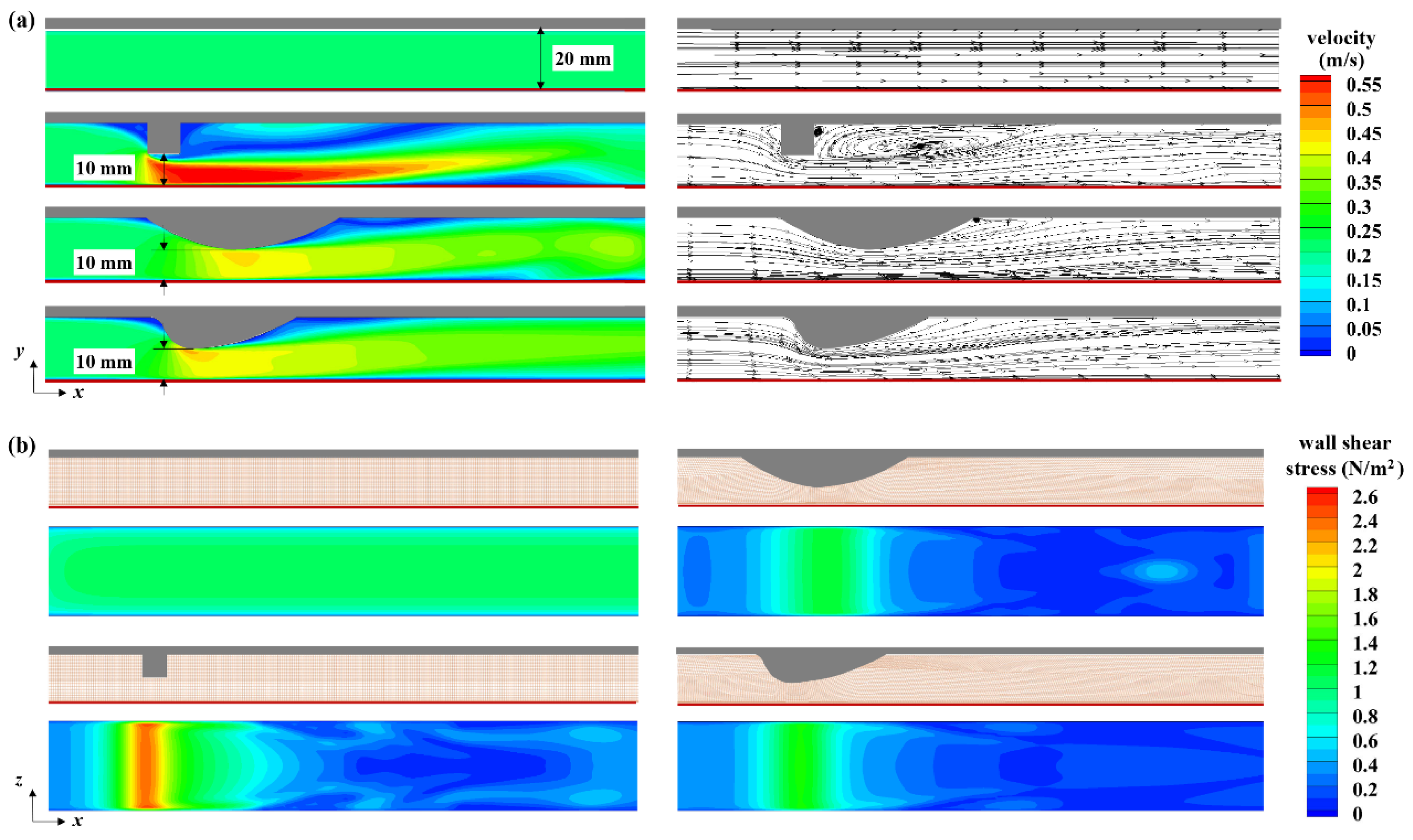
Figure 4a shows the local velocity contours and streamlines of the xy plane when inlet velocity is set as 0.2 m/s. The gaps (shortest distance) between the baffles and the membrane are 10 mm. In the flat channel, the flow velocity distribution is uniform. The mainstream velocity is equal to the inlet velocity. The maximum velocity is about 0.55 m/s after adding a rectangular baffle in the flow channel, 0.45 m/s after adding an arc-shaped baffle, and 0.5 m/s after adding a shield-shaped baffle. The disturbance of the flow is most obvious when adding a rectangular baffle to the flow channel.
Adding a rectangular baffle to the flow channel, the facing area of flow varies intensively. The sudden expansion and contraction of the flow channel generate a large vortex form in the downstream region of the rectangular baffle. Compared with the rectangular baffle, adding an arc-shaped baffle to the flow channel, the change in flow channel area is slow, and the gap between the baffle and the membrane decreases slowly at first and then increases slowly. The flow velocity increases first and then decreases slowly. The arc-shaped baffle can also reduce the area of the recirculating zone formed in the downstream region.
The flow state with the shield-shaped baffle in the flow channel is similar to that with the arc-shaped baffle. When it flows through the shield-shaped baffle, the flow velocity increases first and then decreases slowly. The geometric structure of the shield-shaped baffle is closer to streamline. The computational results also show that the area of the recirculating zone with the shield-shaped baffle is smaller than that with the arc-shaped baffle.

4.3.2. Effect on the Wall Shear Stress of Membrane Surface

Figure 4b shows the local wall shear stress above the membrane surface (xz plane, membrane high-temperature surface) when the velocity of the inlet surface is set at 0.2 m/s. The wall shear stress remains constant above the membrane surface in the flat channel. It increases significantly while adding a rectangular baffle to the flow channel due to the sudden decrease in the flow channel area, which increases the velocity component in the y-axis. However, adding a shield-shaped baffle or an arc-shaped baffle to the flow channel only leads to an insignificant increment of the wall shear stress due to the decrease in the flow channel area relatively slowly.

4.4. Effect on Pressure Drop in the Flow

4.4.1. Influence of the Size of the Gap between the Baffle and the Membrane

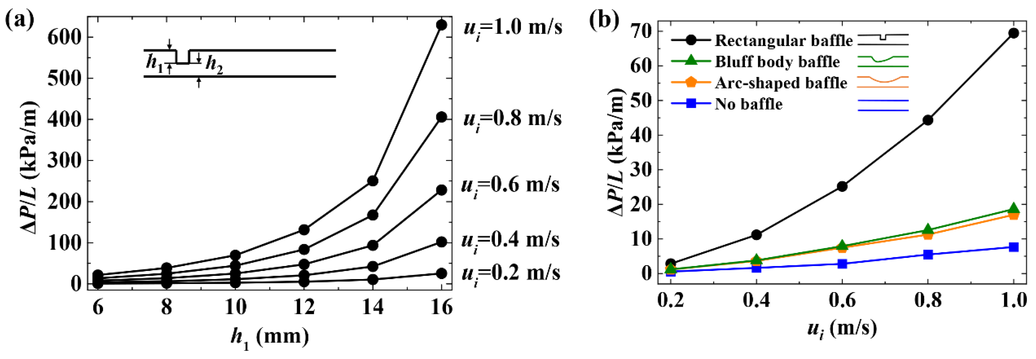
The recirculating zone in the flow channel will consume the energy, resulting in pressure drops. Figure 5a shows the pressure drop when one rectangular baffle is attached to the flow channel. At the same inlet velocity, the smaller the gaps between the rectangular baffles and the membrane (h2), the larger the pressure drop.
The pressure drop increases exponentially with increasing the height of the baffle (h1). When the height of the rectangular baffle is less than 10 mm, the pressure drop along the flow direction is less than 100 kPa/m. The pressure drop in the flow increases with the inlet velocity and baffle height. When the rectangular baffle height increases from 14 mm to 16 mm, the pressure drop increases rapidly. Setting the velocity as 1 m/s at the inlet, the pressure drop per unit length can reach about 650 kPa/m when the height of the rectangular baffles is 16 mm. This is because, with the baffle height increase, the turbulence and recirculating zone will consume more energy, thereby increasing the pressure drop along the flow channel.

4.4.2. Influence of Baffle Geometric Structure

The baffle geometric structure also affects the size of the recirculating zone, which corresponds to a hydrostatic pressure drop in the flow channel. As shown in Figure 5b, the pressure drop is relatively small in a flat flow channel. It increases rapidly after attaching a rectangular baffle (h1 = 10 mm) to the flow channel. Under the same inlet flow velocity, the pressure drops in the flow with an arc-shaped baffle or a shield-shaped baffle are larger than that of the flat channel and smaller than that of the flow channel with the rectangular baffle. This indicates that the geometric structures of the arc-shaped baffle and the shield-shaped baffle are better than those of the rectangular baffle in terms of MD system energy consumption.

4.5. MD Performance

4.5.1. Influence of Baffle Height on Transmembrane Flux

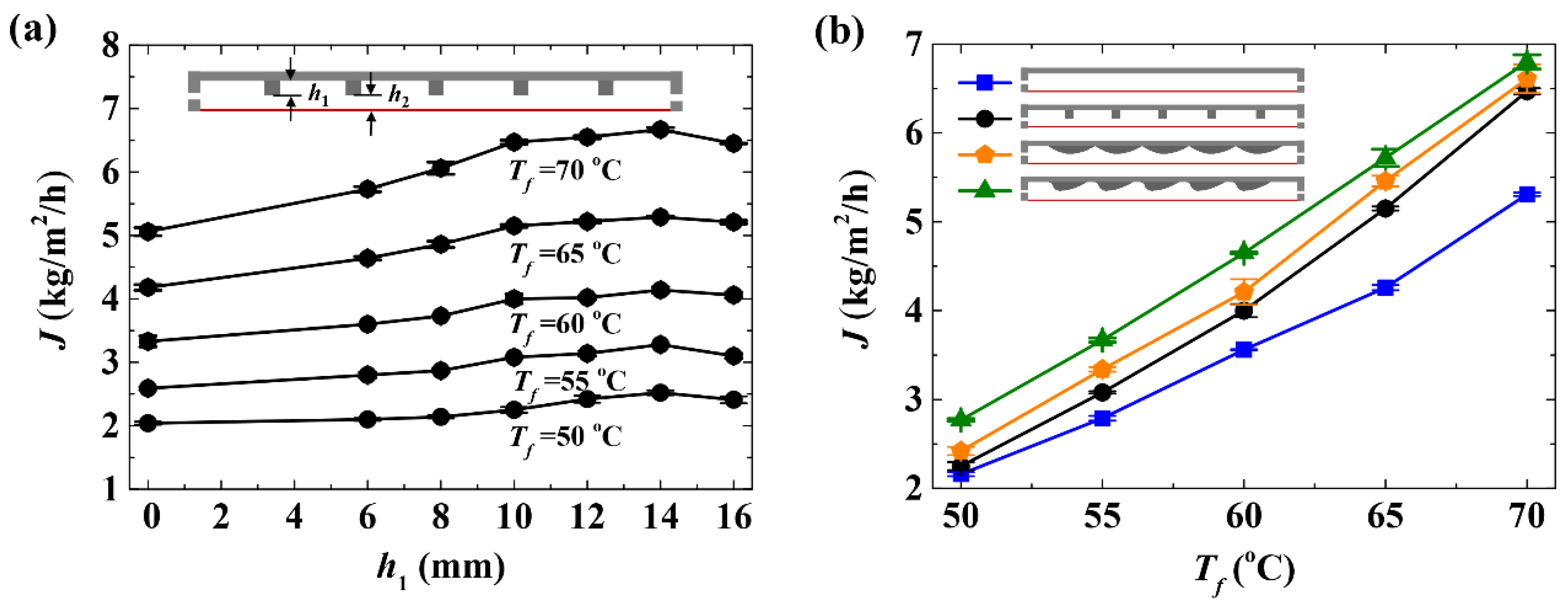
Figure 6a shows the transmembrane flux when five rectangular baffles are attached to the flow channel. The standard deviations of all the MD test results are lower than 0.096. Compared with the transmembrane flux with a flat channel (no baffle), the transmembrane flux of MD can be increased significantly by attaching baffles to the flow channels. When the height of the rectangular baffle (h1) is smaller than 10 mm, the decrease in the gap between the baffles and the membrane (h2) will lead to an increase in the transmembrane flux. After the height of the rectangular baffles (h1) is larger than 10 mm, the increase rate of transmembrane flux becomes slow. When the height of the rectangular baffle (h1) increases to 16 mm (h2 = 4 mm), the transmembrane flux does not increase continuously.
It is believed that the feed in the flow channel may separate into multiple recirculating zones if the gap between multiple rectangular baffles and the membrane (h1) is too small. The feed in the recirculating zone cannot be circulated very well between the feed tank and the MD module; this may make the temperature of the feed in the recirculating zone lower than the feed temperature. When the feed inlet temperature is 50 °C, adding rectangular baffles to the flow channel does not significantly affect transmembrane flux. When the feed inlet temperature is 70 °C, adding the rectangular baffles to the flow channel, the maximum transmembrane flux is 1.3 times that of the flat channel (Figure 6a).

4.5.2. Influence of Baffle Geometric Structure on Transmembrane Flux

Figure 6b shows the experimental results of the influence of baffle geometric structure on transmembrane flux. The gap between the baffles and membrane is 10 mm. The standard deviations of all the MD test results are lower than 0.097. The experimental results indicate that the MD transmembrane flux can be effectively enhanced by geometry modification on the flow channel. At the same feed inlet temperature, the MD module with shield-shaped baffles has the highest transmembrane flux, followed by that with arc-shaped baffles. The MD module without baffles has the minimum transmembrane flux. At the feed inlet temperature of 50 °C, the transmembrane flux of the MD module can only be increased by about 4% with rectangular baffles, which can be increased by about 28% with shield-shaped baffles. The transmembrane flux with shield-shaped baffles also increases by 28% at the feed inlet temperature of 70 °C.

5. Conclusions

This work focuses on designing and modifying the flow channel through the incorporation of baffles as vortex generators. The objective is to reduce polarization effects near the membrane surface, thereby enhancing the MD performance in terms of transmembrane flux and flow resistance. The CFD results demonstrate that the inclusion of baffles effectively reduces the boundary layer thickness by improving velocity near the membrane surface. Consequently, this mitigates the impact of temperature polarization and concentration polarization on MD performance. Altering the geometric structure of the baffles effectively reduces the pressure drop within the flow. Our experimental results validate the feasibility of enhancing MD performance through geometry modification. The experiments reveal that modifying the flow channel by attaching baffles significantly increases the transmembrane flux. It is observed that the geometric structure of the baffles plays a crucial role in determining the MD performance. Specifically, employing shield-shaped baffles proves to be effective in improving MD performance without causing an increase in the pressure drop. The flow channel modification makes it a valuable advancement in the field of membrane distillation and offers promising possibilities for practical utilization.

Author Contributions

Y.Z.: methodology, investigation, validation, software, formal analysis, data curation, writing—original draft; X.M.: supervision, writing—review and editing; J.S.: investigation, data curation; F.G.: supervision, conceptualization, investigation, validation, writing—review and editing, project administration, funding acquisition. All authors have read and agreed to the published version of the manuscript.

Funding

This work was supported by the Fundamental Research Funds for the Central Universities (DUT21JC10).

Data Availability Statement

The data presented in this study are available on request from the corresponding author.

Conflicts of Interest

The authors declare no conflict of interest.

Nomenclature

Awetted surface area of the computational domain (m2)
cpspecific heat (J/kg/K)
dhhydraulic diameter (m)
ggravitational acceleration (m/s2)
h1height of the baffle (m)
h2distance between the baffle and the membrane surface (m)
Hheight of the computational domain (m)
Jtransmembrane flux (kg/m2/h)
kthermal conductivity (W/m/K)
Llength of computational domain (m)
Ppressure (Pa)
Tffeed temperature (°C)
uavmean velocity along the flow direction (m/s)
uiinlet velocity of the CFD simulation (m/s)
u, v, wvelocity component along x, y, z (m/s)
Vvolume of computational domain (m3)
Wwidth of computational domain (m)
x, y, zcartesian coordinates (m)
ReReynolds number
Greek letters
μdynamic viscosity (Pa·s)
νkinematic viscosity (m2/s)
ρdensity (kg/m3)
ΔPpressure drop along the flow direction (kPa)

References

  1. Qtaishat, M.; Matsuura, T.; Kruczek, B.; Khayet, M. Heat and mass transfer analysis in direct contact membrane distillation. Desalination 2008, 219, 272–292. [Google Scholar] [CrossRef]
  2. Kalla, S.; Piash, K.P.S.; Sanyal, O. Anti-fouling and anti-wetting membranes for membrane distillation. J. Water Process Eng. 2022, 46, 102634. [Google Scholar] [CrossRef]
  3. Cong, S.; Liu, X.; Guo, F. Membrane distillation using surface modified multi-layer porous ceramics. Int. J. Heat Mass Transf. 2019, 129, 764–772. [Google Scholar] [CrossRef]
  4. Khayet, M.; Matsuura, T. Membrane Distillation: Principles and Applications; Elsevier: Amsterdam, The Netherlands, 2011. [Google Scholar]
  5. Martínez-Díez, L.; Vázquez-González, M.I.; Florido-Díaz, F.J. Temperature polarization coefficients in membrane distillation. Sep. Sci. Technol. 1998, 33, 787–799. [Google Scholar] [CrossRef]
  6. Vink, H.; Chishti, S.A.A. Thermal osmosis in liquids. J. Membr. Sci. 1976, 1, 149–164. [Google Scholar] [CrossRef]
  7. Martínez, L.; Rodríguez-Maroto, J.M. On transport resistances in direct contact membrane distillation. J. Membr. Sci. 2007, 295, 28–39. [Google Scholar] [CrossRef]
  8. Razmjou, A.; Arifin, E.; Dong, G.; Mansouri, J.; Chen, V. Superhydrophobic modification of TiO2 nanocomposite PVDF membranes for applications in membrane distillation. J. Membr. Sci. 2012, 415–416, 850–863. [Google Scholar] [CrossRef]
  9. Anvari, A.; Azimi Yancheshme, A.; Kekre, K.M.; Ronen, A. State-of-the-art methods for overcoming temperature polarization in membrane distillation process: A review. J. Membr. Sci. 2020, 616, 118413. [Google Scholar] [CrossRef]
  10. Srisurichan, S.; Jiraratananon, R.; Fane, A.G. Mass transfer mechanisms and transport resistances in direct contact membrane distillation process. J. Membr. Sci. 2006, 277, 186–194. [Google Scholar] [CrossRef]
  11. Ortiz De Zarate, J.M.; Velazquez, A.; Pena, L.; Mengual, J.I. Influence of temperature polarization on separation by membrane distillation. Sep. Sci. Technol. 1993, 28, 1421–1436. [Google Scholar] [CrossRef]
  12. Martínez-Díez, L.; Vázquez-González, M.I. Temperature and concentration polarization in membrane distillation of aqueous salt solutions. J. Membr. Sci. 1999, 156, 265–273. [Google Scholar] [CrossRef]
  13. Tijing, L.D.; Woo, Y.C.; Shim, W.G.; He, T.; Choi, J.S.; Kim, S.H.; Shon, H.K. Superhydrophobic nanofiber membrane containing carbon nanotubes for high-performance direct contact membrane distillation. J. Membr. Sci. 2016, 502, 158–170. [Google Scholar] [CrossRef]
  14. Wei, Z.; Jin, Y.; Li, J.; Jia, L.; Ma, Y.; Chen, M. Preparation of superhydrophobic PVDF composite membrane via catechol/polyamine co-deposition and Ag nanoparticles in-situ growth for membrane distillation. Desalination 2022, 529, 115649. [Google Scholar] [CrossRef]
  15. Jia, Y.; Xu, G.; An, X.; Hu, Y. Robust reduced graphene oxide composite membranes for enhanced anti-wetting property in membrane distillation. Desalination 2022, 526, 115549. [Google Scholar] [CrossRef]
  16. Shafieian, A.; Rizwan Azhar, M.; Khiadani, M.; Kanti Sen, T. Performance improvement of thermal-driven membrane-based solar desalination systems using nanofluid in the feed stream. Sustain. Energy Technol. Assess. 2020, 39, 100715. [Google Scholar] [CrossRef]
  17. Shekarchi, N.; Shahnia, F. A comprehensive review of solar-driven desalination technologies for off-grid greenhouses. Int. J. Energy Res. 2019, 43, 1357–1386. [Google Scholar] [CrossRef]
  18. Hejazi, M.A.; Bamaga, O.A.; Al-beirutty, M.H.; Gzara, L. Separation and purification technology effect of intermittent operation on performance of a solar-powered membrane distillation system. Sep. Purif. Technol. 2019, 220, 300–308. [Google Scholar] [CrossRef]
  19. Nawi, N.I.M.; Bilad, M.R.; Zolkhiflee, N.; Nordin, N.A.H.; Lau, W.J.; Narkkun, T.; Faungnawakij, K.; Arahman, N.; Mahlia, T.M.I. Development of a novel corrugated polyvinylidene difluoride membrane via improved imprinting technique for membrane distillation. Polymers 2019, 11, 865. [Google Scholar] [CrossRef]
  20. Kharraz, J.A.; Bilad, M.R.; Arafat, H.A. Flux stabilization in membrane distillation desalination of seawater and brine using corrugated PVDF membranes. J. Membr. Sci. 2015, 495, 404–414. [Google Scholar] [CrossRef]
  21. Usta, M.; Anqi, A.E.; Oztekin, A. Reverse osmosis desalination modules containing corrugated membranes—Computational study. Desalination 2017, 416, 129–139. [Google Scholar] [CrossRef]
  22. Peng, Y.; Dong, Y.; Fan, H.; Chen, P.; Li, Z.; Jiang, Q. Preparation of polysulfone membranes via vapor-induced phase separation and simulation of direct-contact membrane distillation by measuring hydrophobic layer thickness. Desalination 2013, 316, 53–66. [Google Scholar] [CrossRef]
  23. Liu, L.; He, H.; Wang, Y.; Tong, T.; Li, X.; Zhang, Y.; He, T. Mitigation of gypsum and silica scaling in membrane distillation by pulse flow operation. J. Membr. Sci. 2021, 624, 119107. [Google Scholar] [CrossRef]
  24. Seo, J.; Kim, Y.M.; Kim, J.H. Spacer optimization strategy for direct contact membrane distillation: Shapes, configurations, diameters, and numbers of spacer filaments. Desalination 2017, 417, 9–18. [Google Scholar] [CrossRef]
  25. Kim, Y.D.; Francis, L.; Lee, J.G.; Ham, M.G.; Ghaffour, N. Effect of non-woven net spacer on a direct contact membrane distillation performance: Experimental and theoretical studies. J. Membr. Sci. 2018, 564, 193–203. [Google Scholar] [CrossRef]
  26. Alwatban, A.M.; Alshwairekh, A.M.; Alqsair, U.F.; Alghafis, A.A.; Oztekin, A. Performance improvements by embedded spacer in direct contact membrane distillation—Computational study. Desalination 2019, 470, 114103. [Google Scholar] [CrossRef]
  27. Camacho, L.M.; Dumée, L.; Zhang, J.; de Li, J.; Duke, M.; Gomez, J.; Gray, S. Advances in membrane distillation for water desalination and purification applications. Water 2013, 5, 94–196. [Google Scholar] [CrossRef]
  28. Soukane, S.; Ghaffour, N. Showerhead feed distribution for optimized performance of large scale membrane distillation modules. J. Membr. Sci. 2021, 618, 118664. [Google Scholar] [CrossRef]
  29. Rabie, M.; Elkady, M.F.; El-Shazly, A.H. Effect of channel height on the overall performance of direct contact membrane distillation. Appl. Therm. Eng. 2021, 196, 117262. [Google Scholar] [CrossRef]
  30. Mabrouk, A.; Elhenawy, Y.; Moustafa, G. Experimental evaluation of corrugated feed channel of direct contact membrane distillation. J. Membr. Sci. Technol. 2016, 6, 2. [Google Scholar] [CrossRef]
  31. Elhenawy, Y.; Elminshawy, N.A.S.; Bassyouni, M.; Alhathal Alanezi, A.; Drioli, E. Experimental and theoretical investigation of a new air gap membrane distillation module with a corrugated feed channel. J. Membr. Sci. 2020, 594, 117461. [Google Scholar] [CrossRef]
  32. Kuang, Z.; Long, R.; Liu, Z.; Liu, W. Analysis of temperature and concentration polarizations for performance improvement in direct contact membrane distillation. Int. J. Heat Mass Transf. 2019, 145, 118724. [Google Scholar] [CrossRef]
  33. Cai, J.; Luo, Y.; Chen, J.; Guo, F. Investigation of interfacial crystallization fouling behaviors and membrane re-functionalization based on a long-distance membrane distillation module. Desalination 2022, 534, 115800. [Google Scholar] [CrossRef]
  34. Khan, S.B.; Irfan, S.; Lam, S.S.; Sun, X.; Chen, S. 3D printed nanofiltration membrane technology for waste water distillation. J. Water Process Eng. 2022, 49, 102958. [Google Scholar] [CrossRef]
  35. Ismail, M.S.; Mohamed, A.M.; Poggio, D.; Walker, M.; Pourkashanian, M. Modelling mass transport within the membrane of direct contact membrane distillation modules used for desalination and wastewater treatment: Scrutinising assumptions. J. Water Process Eng. 2022, 45, 102460. [Google Scholar] [CrossRef]
Figure 1. AGMD test system with various baffle structures above the membrane in the flow channel. (a) SEM image of the surface morphology of the porous membrane. (b) Schematic diagram of the AGMD test unit. (c) Photos of the feed flow chamber (PMMA) with various baffle (Nylon) structures fabricated by 3D printing. (d) Schematic diagram and design parameters of the AGMD module with various baffle structures in the feed channel. h1 and h2 represent the height of the baffles and the gap (shortest distance) between the baffle and membrane surface, respectively.
Separations 10 00485 g001
Figure 2. The size of the three-dimensional computational domain for CFD simulations and its local section meshes. (a) The local section grids of the flat flow channel and flow channel with one baffle. (b) The computational domain of the flow channel with five rectangular baffles and its local section meshes. In the y direction, the height of the first layer grid above the membrane surface is 1 × 10⁻⁵ m.
Separations 10 00485 g002
Figure 3. The influence of the number of baffles and the gap (shortest distance) between the baffles and the membrane on the flow streams in the flow channel. (a) Local velocity contours and streamlines of xy plane when the gaps between the baffle and the membrane (h2) are changed. Only one rectangular baffle is attached to the flow channel. The size of the gap between the baffle and the membrane varies from 4 to 14 mm and increases by increments of 2 mm. (b) Local velocity contours and streamlines of xy plane with five rectangular baffles in the flow channel. The inlet velocity (ui) is set at 0.2 m/s. The size of the gaps between the baffles and the membrane are 4 mm and 8 mm.
Separations 10 00485 g003
Figure 4. The CFD simulated flow states in the channels with no baffle (flat channel), rectangular baffle, arc-shaped baffle, and shield-shaped baffle, respectively. The inlet flow velocity is set at 0.2 m/s. (a) Local velocity contours and streams in xy plane. (b) Local wall shear stress of membrane surface (xz plane, membrane high temperature surface).
Separations 10 00485 g004
Figure 5. Pressure drop along the flow direction with different baffle structures. (a) With a rectangular baffle in the flow channel, the pressure drop along the flow direction is affected by the initial flow velocity and baffle height (h1). The original size of the channel gap is 20 mm (h1 + h2 = 20 mm). (b) With a certain baffle height (h1 = 10 mm), various baffle structures lead to different values of pressure drop along the flow direction. ui is the flow velocity at the inlet (boundary condition of the numerical solution).
Separations 10 00485 g005
Figure 6. The MD experimental results with different baffle geometric structure in the flow channel. (a) The MD transmembrane flux after attaching five rectangular baffles to the flow channel. The height of the baffle is from 6 to 16 mm and increases by increments of 2 mm. (b) The MD transmembrane flux after attaching baffles with different geometric structures in the feed flow channel. The number of baffles is also five. The gap (shortest distance) between the baffles and the membrane is 10 mm.
Separations 10 00485 g006
Table 1. Results of the mesh independence tests.
CaseNumber of Cellsui (m/s)ReΔP/L (Pa/m)
Case 1280,0000.1239277
Case 2560,0000.1239278
Case 31,740,0000.1239278
Table 2. The physical properties of the fluid used in the CFD simulation.
Fluidρ (kg/m3)cp (J/(kg·K))k (W/(m·K))μ (Pa·s)
Pure water998.24182.10.6131.003 × 10−3
Disclaimer/Publisher’s Note: The statements, opinions and data contained in all publications are solely those of the individual author(s) and contributor(s) and not of MDPI and/or the editor(s). MDPI and/or the editor(s) disclaim responsibility for any injury to people or property resulting from any ideas, methods, instructions or products referred to in the content.