Article

Performance Improvement of Hydrofoil with Biological Characteristics: Tail Fin of a Whale

1
Key Laboratory of Metallurgical Equipment and Control Technology, Wuhan University of Science and Technology, Ministry of Education, Wuhan 430081, China
2
Hubei Key Laboratory of Mechanical Transmission and Manufacturing Engineering, Wuhan University of Science and Technology, Wuhan 430081, China
*
Authors to whom correspondence should be addressed.
Processes 2021, 9(9), 1656; https://doi.org/10.3390/pr9091656
Submission received: 26 August 2021 / Revised: 7 September 2021 / Accepted: 10 September 2021 / Published: 14 September 2021
(This article belongs to the Special Issue CFD Modelling and Simulation of Water Turbines)

Abstract

:
In order to improve the hydrodynamic performance of hydrofoils, this paper shows excellent hydrodynamic performance according to the flapping motion of fish through the tail fin. The Naca66 hydrofoil is used as the original hydrofoil and the trailing edge flap configuration is added. Ansys-fluent is used to analyze the relationship between the structural parameters (length and angle) of the flap and the hydrodynamic performance of the hydrofoil, the reliability of CFD numerical simulation is verified by PIV experiment. It is found that the hydrofoil, with clockwise rotating short flap, can significantly improve the hydrodynamic performance of a hydrofoil at a small angle of attack; at a high angle of attack, the hydrofoil with counterclockwise flap can increase the critical stall angle and slightly improve the hydrodynamic performance of the hydrofoil. The hydrodynamic performance of hydrofoil with rotatable short flaps reported in this paper can provide valuable information for the design and optimization of this kind of hydrofoil.

1. Introduction

Hydrofoil, as an auxiliary component of high-speed ships, is widely used in hydrofoil ships and planing boats. By installing a hydrofoil on the bottom of hydrofoil ships, it can generate huge lifting force to lift the ship off the water at high speed, thus greatly reducing the drag of water to the ship and wave-making drag, and also reducing the interference of waves to the stability of the ship [1,2]. Therefore, in order to improve the performance of hydrofoil ships, many scholars have carried out research on hydrofoil lift and drag reduction.
Compared with airfoils, the flow medium of a hydrofoil is water, and the density and viscosity of water are much greater than that of air. Therefore, the lift generated by a hydrofoil with the same shape and moving state is much greater than that generated by a wing. At the same time, the friction resistance and differential pressure resistance of hydrofoils are also increased accordingly. However, scholars’ research on hydrofoils and airfoils has the same goal of improving performance (increasing lift and reducing drag). Scholars have undertaken much research on increasing lift and reducing drag of airfoils, mainly including bionics [3,4], vortex generators [5,6], synthetic jet [7,8], and multi-element airfoil [9,10]. However, the working environment of the hydrofoil is quite different from that of the wing, and not necessarily applicable. In the research of hydrofoils, inspired by bird and fishes, the applications of flapping foils as energy harvesting devices have gradually attracted attention in recent decades [11,12]. For example, dolphins and sharks exhibit excellent hydrodynamic performance, including high cruising speed, high efficiency, and low noise through the flapping motion of their caudal fins [13]. Johari [14] found that a full-span wing with leading-edge tubercles increases the lift coefficient by as much as 50% in the post-stall regime at a Reynolds number of Re = 1.83 × 10⁵; the idea was originally motivated by the physiological structures of humpback whales. But Rostamzadeh [15] and Skillen [16] also shed light on the implementation of leading-edge tubercles when they were used on aerofoils and wings immersed in free-streams. Both studies found that the tubercles led to the formation of secondary flows due to the presence of strong spanwise pressure gradients, and Chang Cai [17] also found that modified foils performed worse than the baseline foil at pre-stall angles, while the lift coefficients at high angles of attack of the modified foils were increased. In addition to applying bionics to the design of hydrofoil structure to improve hydrodynamic performance, there are also methods to optimize the structure according to the flow field. Eun Jung Chae [18] conducted numerical simulation analysis on the flexible hydrofoil and found that the compliant hydrofoil can well adapt to the fluid flow conditions, but many hydrofoils in the hydrofoil boat are rigid, so they can not meet the design requirements of the hydrofoil boat. Manhar Dhanak [19] analyzed the performance characteristics of a shallowly submerged hydrofoil with an internal slot that allowed flow ventilation from the pressure side of the hydrofoil to the suction side and found that significant improvements in hydrofoil performance in terms of lift, drag, and lift-to-drag ratio at high angles of attack. Belamadi [20] studied the effect of a straight internal slot on an S809 airfoil using numerical simulations. CFD analysis was performed for different configurations by varying slot location, width, and slope at Reynolds number of 106. Results showed that aerodynamic improvement was found only in the specific range of 10–20°. Although these studies have improved the hydrodynamic performance of hydrofoils to some extent, many are only applicable to fixed working conditions or high angle of attack. In a small angle of attack, the hydrodynamic performance of some hydrofoils will even decrease. To solve this problem, researchers have proposed biomimetic methodologies by observing the motion of fish in the sea. During the long periods of evolution, fish have developed mature flow control mechanisms that can be applied to a wide variety of engineering designs. CD Wilga [21] found that sharks change the direction of vortex shedding by swinging their fins, which may increase the shark’s vertical maneuverability; George V. Lauder [22] found that the median fins of fishes consist of the dorsal, anal, and caudal fins and have long been thought to play an important role in generating locomotor force during both steady swimming and maneuvering; Michael Sfakiotakis [23] found that fish swim either by the body and/or caudal fin movements or using median and/or paired fin propulsion. Some fish swim upward or downward in the sea by swinging their tail fins. For example, when the whale swims upward, the tail fin is downward. When the whale swims downward, the tail fin is upward, as shown in Figure 1.
In this paper, the excellent hydrodynamic performance is reflected by learning from the flapping movement of the whale through the tail fin. Taking the naca66 hydrofoil as the original model, the tail edge flap is added to improve the hydrodynamic performance of the hydrofoil. Ansys-fluent is used to analyze the influence of the angle and length of trailing edge flap and different Reynolds numbers on the hydrodynamic performance of hydrofoil, and PIV experiment is used to verify the reliability of CFD numerical simulation.

2. Model

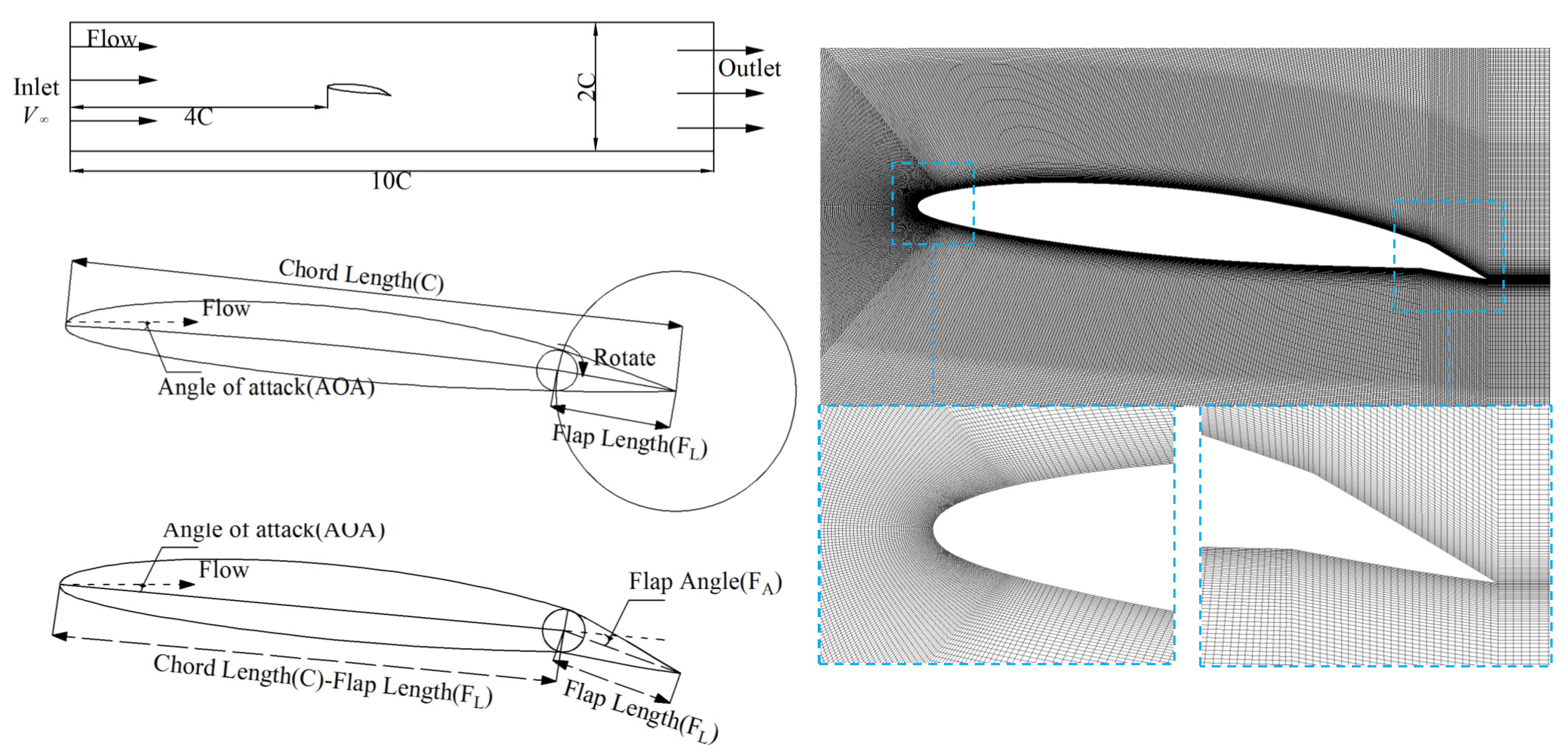
2.1. Calculation Model

A NACA66 hydrofoil was used in the present research. The hydrofoil has a relative maximum thickness of 12% at 45% chord length from the leading edge and a relative maximum camber of 2% at 50% from the leading edge. Flap modification of naca66 hydrofoil trailing edge. The effects of flap length (FL) and flap angle (FA) on hydrofoil performance under different Reynolds numbers are analyzed by CFD. Whenever the flap angle or flap length is changed, it needs to be re-modeled and meshed. The total chord length of the hydrofoil is C = 75 mm. Select flaps with different lengths to rotate (clockwise rotation: FA > 0, counterclockwise rotation: FA < 0) to obtain hydrofoils with different angle flaps. The reliability of CFD simulation is verified by PIV experiment and ICEM-CFD is used to mesh the structure of the hydrofoil, regardless of the flap shape, the number of grid nodes per unit length remains almost unchanged, so the total number of grids will not change greatly, in order to ensure the calculation accuracy, y + of the hydrofoil is less than 1, the fluid domain and fluid mesh are shown in Figure 2.
Using ANSYS-Fluent as the numerical simulation tool, k-ω SST Turbulence model can capture the flow field around the dynamic hydrofoil for various ranges of Reynolds numbers [24,25,26]. Pressure and velocity coupling algorithms adopt SIMPLEC; spatial discretization scheme is QUICK; the convergence accuracy is less than 10−4; time step is 10−4; specific CFD setting conditions are shown in Table 1. The lift coefficient Cl and drag coefficient Cd are monitored to compare the effects of flap on hydrofoil hydrodynamic performance.
C l = l 0.5 ρ V 2 C   C d = d 0.5 ρ V 2 C
where l is lift force; d is drag force; pinlet is Inlet static pressure; 0.5ρV2 is dynamic pressure.

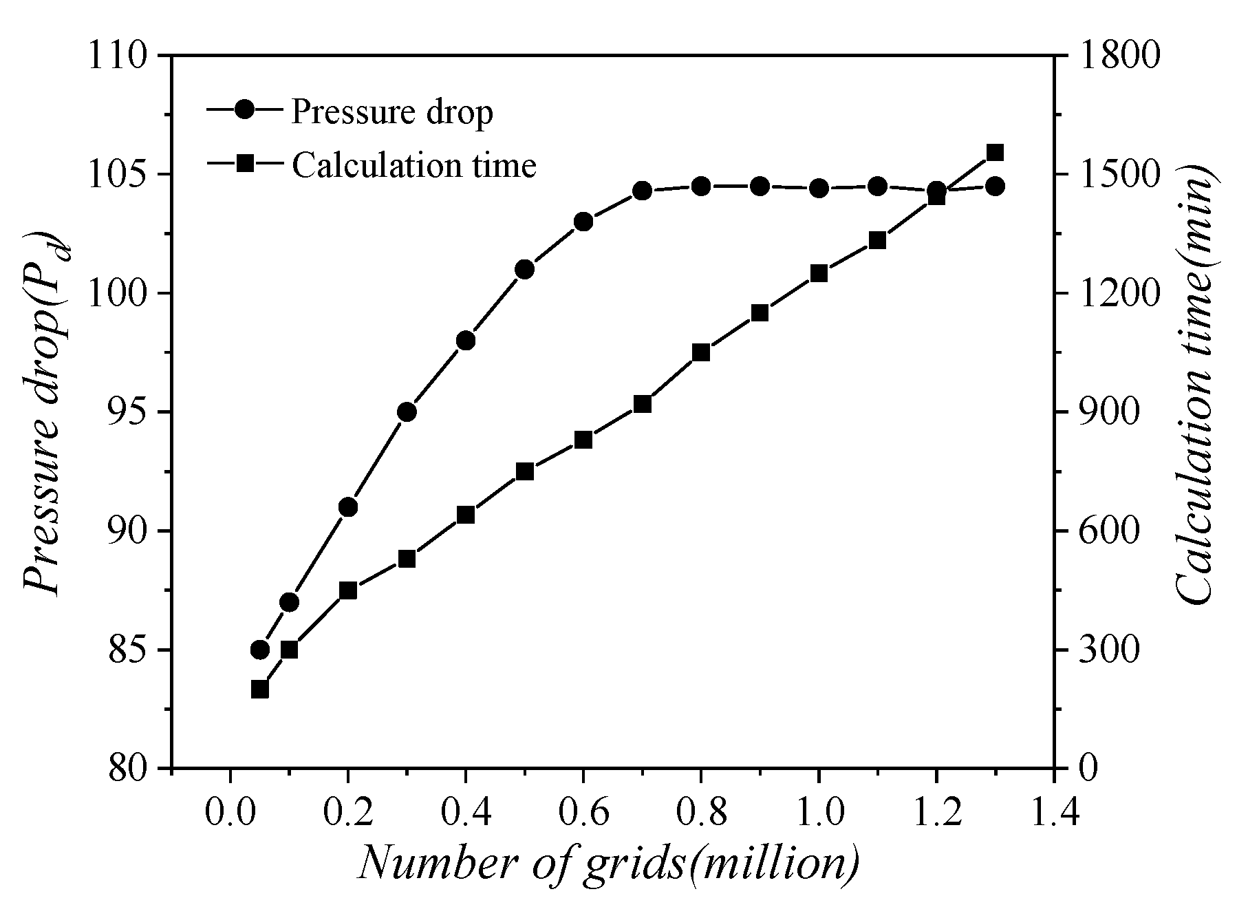
2.2. Independence of the Number of Grids and Reliability Verification

As shown in Figure 3, when the number of meshes reached a certain value, further increases in the number of meshes had no significant effect on the calculation results but increased the calculation time. Considering the balance between solution accuracy and calculation time, the number of grids selected for this study was approximately 0.9 million.
This paper uses the PIV experiment to verify the stator blade shape to ensure the accuracy of CFD simulation. The experimental equipment is shown in Figure 4. In the PIV experiment, in order to reduce the error caused by the double refraction caused by the laser, the entire cascade runner is made of plexiglass. Its refractive index is close to water, The interface between the flow channel and the pipe is made by 3D printing. In order to avoid the reflection of the laser on the surface of the non-flow channel and affect the image capture, black processing is performed around the shooting area. The main equipment used for PIV measurement experiment includes: Dual cavity UV laser; PIV Camera; Timing circuit; DynamicStudio.
In order to verify the accuracy of the CFD simulation flow state, the vector diagram measured by PIV is shown in Figure 5a, which is a CFD simulation trace diagram with the same boundary conditions. It can be seen from the figure that the vortex position simulated by CFD is very close to the vortex position measured by PIV. Then extract the velocity distribution data at the trailing edge of the hydrofoil (FL = 0.30 C; FA = 10°; AOA = 6°); as shown in Figure 5b, the velocity distribution is also close. This shows that the simulation has high reliability.

3. Results and Analysis

3.1. Influence of Flap Angle (FA) on Hydrodynamic Performance of Hydrofoil

Figure 6 shows the hydrodynamic performance and streamline of hydrofoils with different flap angles. This paper mainly analyzes the influence of flap on hydrofoil according to hydrodynamic performance, so the flow field is not analyzed in detail, However, as can be seen in Figure 6a, the lift coefficient of the hydrofoil increases with the increase of the angle of attack, then decreases and then increases again, this shows that stall and deep stall effects appear in this range of attack angle. In order to explain this phenomenon, the flow field is analyzed for AOA = 9°, AOA = 12°, AOA = 15°, as shown in Figure 6d. and there will be no more analysis later.
Combined with Figure 6a,d, it can be found that when the angle of attack is small, Due to the Coanda effect, the flow of the hydrofoil is an attached flow. With the increase of the angle of attack, the suction surface of the hydrofoil produces a pressure gradient, resulting in flow separation at the trailing edge of the hydrofoil and small-scale trailing edge vortex (AOA = 9°); when the angle of attack increases, the pressure gradient increases, the hydrofoil has complete flow separation, resulting in large-scale trailing edge vortex (AOA = 12°) and the hydrofoil stalls; With the increase of the angle of attack again, the leading edge vortex and double separation vortex appear in the hydrofoil (AOA = 15°), the hydrofoil has a deep stall and the lift coefficient rises again. It can be seen that the size of vortex affects the hydrodynamic performance of the hydrofoil. The larger the vortex, the worse the hydrodynamic performance.
It can be seen from Figure 6a–c that the hydrodynamic performance of the hydrofoil with clockwise flap rotation(FA = 5°, FA = 10°) is obviously better than that of the hydrofoil with counterclockwise flap rotation(FA = 0°, FA = −5°, FA = −10°) at a small angle of attack (AOA ≤ 6°), this is because when the flap rotates clockwise, it increases the differential pressure up and down the trailing edge and increases the lift coefficient, but it also increases the differential pressure resistance at the leading edge and trailing edge, so the resistance coefficient will also increase. Because the angle of attack is small (AOA ≤ 6°), the influence of the flap on lift coefficient is greater than that on the drag coefficient, so the hydrodynamic performance of hydrofoil with a clockwise flap is better. With the increase of the angle of attack, the influence of the flap on the lift coefficient and the drag coefficient is almost the same, so the lift drag ratio of the hydrofoil is very close with or without flap. When the flap rotates counterclockwise, part of the water flow at the trailing edge of the hydrofoil will change the direction and change the pressure distribution due to the Coanda effect, the existence of flap not only reduces the pressure difference between the upper and lower trailing edges, resulting in the decrease of lift coefficient, but also reduces the pressure difference between the leading and trailing edges of hydrofoil, resulting in the decrease of the drag coefficient. Although the counterclockwise flap will reduce the hydrodynamic performance of hydrofoil, the lift decreases little under the condition of critical stall angle, indicating that we can try to change the flap angle to increase the critical stall angle.

3.2. Influence of Flap Length (FL) on Hydrodynamic Performance of Hydrofoil

It is concluded in the previous section that the clockwise rotation of the flap can improve the hydrodynamic performance of the hydrofoil. In this section, two models (FA = 5°, FA = 10°) with clockwise flap rotation are used to analyze the influence of flap length (FL) on the hydrofoil’s hydrodynamic performance, as shown in Figure 7. It can be seen from the figure that changing the flap length has little effect on the critical stall angle (the slope is almost constant). Under the same angle of attack, the drag coefficient increases with the increase of flap length, and the lift coefficient increases with the increase of flap length before stall; When AOA ≥ 12°, the lift coefficient decreases with the increase of flap length, but it is always greater than the original hydrofoil. The influence of flap length on the hydrofoil with a larger flap angle is more obvious. This is because the larger the flap angle is, the increase of flap length will increase the pressure difference between the upper and lower ends of the hydrofoil trailing edge (lift coefficient increases), and also increase the pressure difference resistance at both ends of the hydrofoil’s leading edge and trailing edge (drag coefficient increases). However, with the change of angle of attack, the influence of flap length on lift coefficient and the drag coefficient is different (slope is different). As can be seen from Figure 7e,f, compared with the original hydrofoil, when AOA = 0° and AOA = 3°, the influence of flap on lift coefficient is greater than that on drag coefficient, and the hydrodynamic performance with flap is always better than that of the original hydrofoil; With the increase of angle of attack (AOA = 6°), the influence of long flap (FL = 0.25C, FL = 0.3C) on drag coefficient is greater than that on lift coefficient. The hydrodynamic performance of a hydrofoil with a long flap is worse than that of the original hydrofoil; Until AOA = 9°, the hydrodynamic performance of the original hydrofoil is the best, and the flap will reduce the hydrodynamic performance of the hydrofoil. It shows that the flap can improve the hydrodynamic performance of the hydrofoil in the small angle of attack range, a hydrofoil with a short flap has a better angle of attack characteristics and can maintain a higher hydrodynamic performance in a wider angle of attack range.

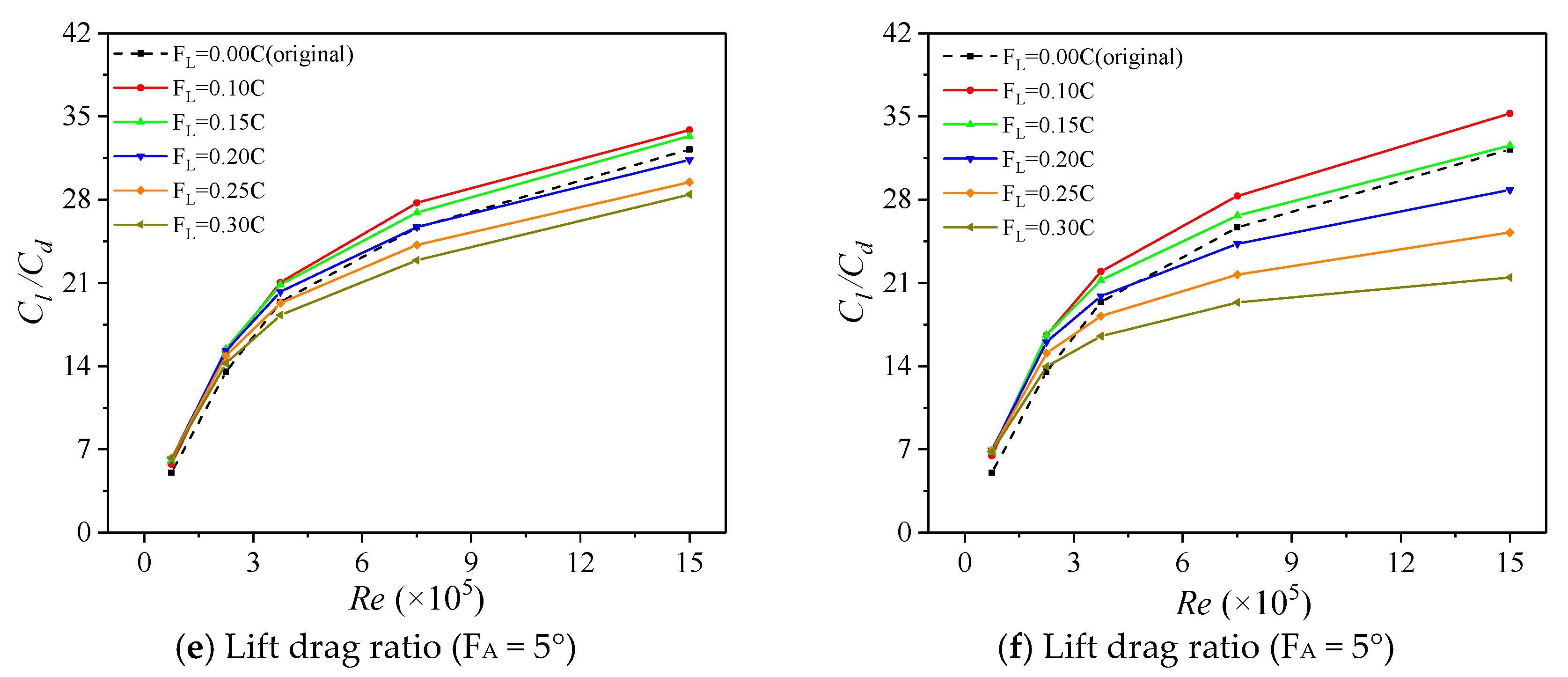
3.3. Influence of Flap on Hydrodynamic Performance of Hydrofoil at Different REYNOLDS Numbers

Through the analysis of two sections, it was found that when AOA = 6°, the lift-drag ratio of the hydrofoil reached the maximum and the hydrodynamic performance of the hydrofoil was the best. Therefore, in this section, we took the angle of attack as quantitative (AOA = 6°) and Reynolds number and flap length (FL) as variables to analyze the influence of different Reynolds numbers on the hydrodynamic performance of hydrofoils with flaps of different lengths, as shown in Figure 8. It can be seen from the figure that the lift coefficient increases with the increase of the Reynolds number and the drag coefficient decreases with the increase of Reynolds number, but the slopes of both decrease with the increase of the Reynolds number, which causes the slope of the lift–drag ratio to decrease with the increase of Reynolds number. By analyzing the lift-drag ratio diagram (Figure 6e,f), it can be found that when the Reynolds number is small (Re ≤ 2.1 × 10⁵), the hydrodynamic performance of the hydrofoil with a flap was better than that of the original hydrofoil. With the increase of Reynolds number, the hydrodynamic performance of the hydrofoil with a long flap (FL = 0.2C; FL = 0.25C; FL = 0.3C) is worse than that of the original hydrofoil. It shows that the hydrofoil with a short flap has a better Reynolds number characteristics and can maintain a higher hydrodynamic performance in a wider Reynolds number range.

4. Conclusions

In this paper, ansys-fluent numerical calculation software is used to analyze the influence of flap on the hydrodynamic performance of naca66 hydrofoil. The accuracy of CFD simulation was verified by the PIV experiment, and the influence of flap length (FL) and flap angle (FA) on the hydrodynamic performance of the hydrofoil was studied through the lift coefficient and drag coefficient of the hydrofoil. The main conclusions include:
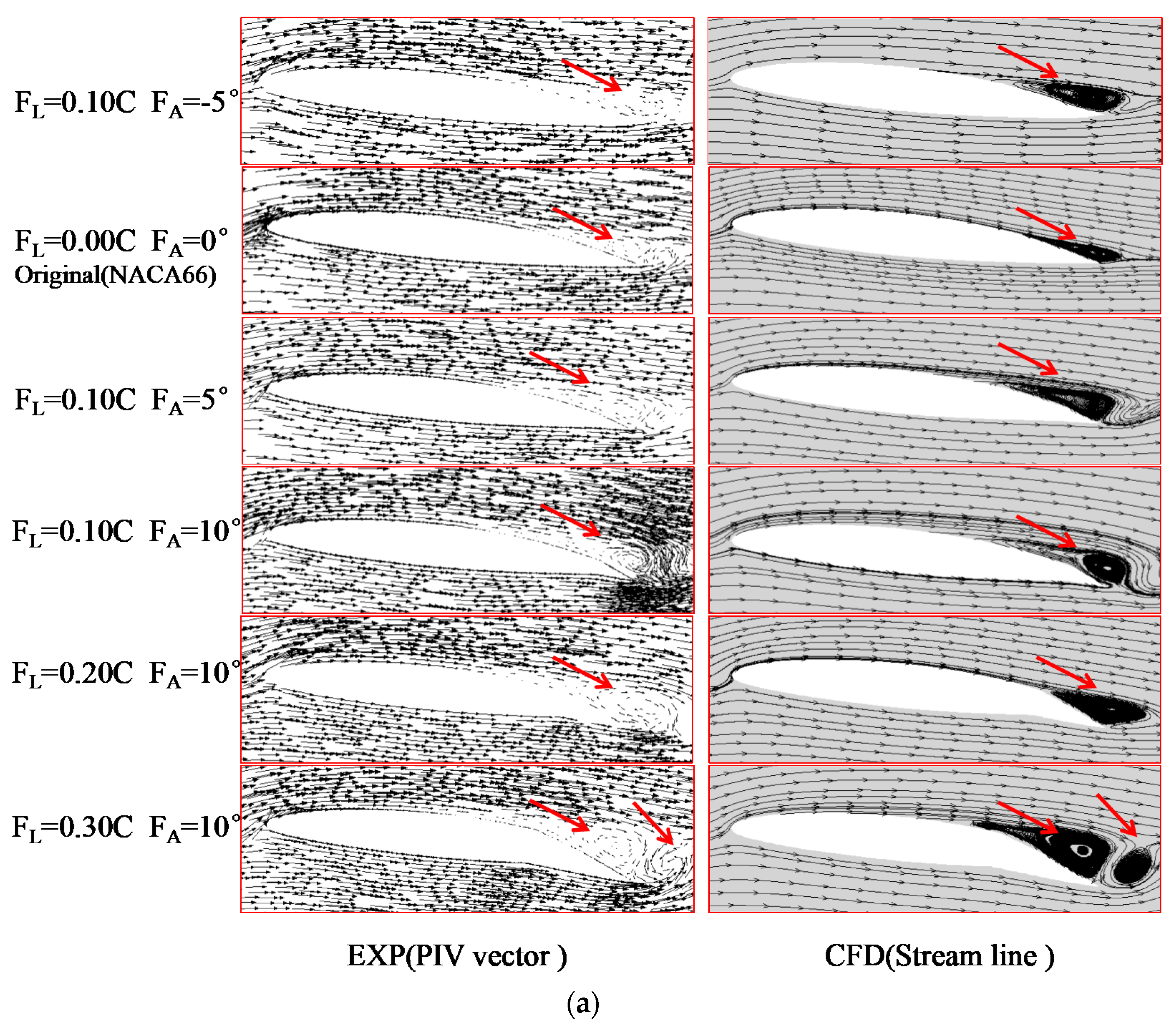
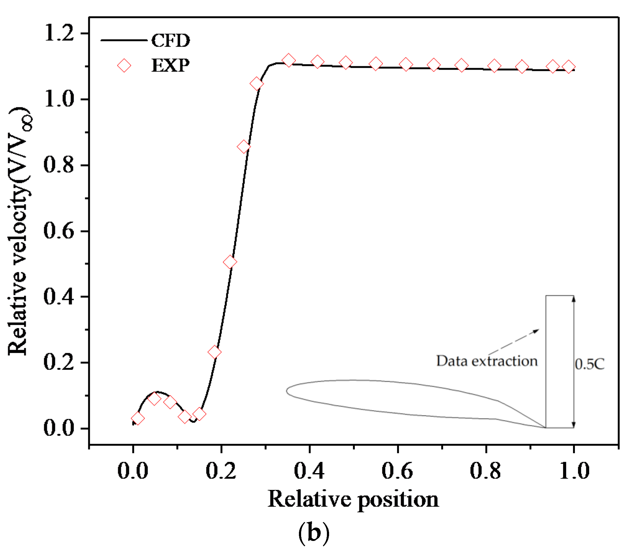
  • By comparing the vector diagram of the PIV experiment with the trace diagram of CFD, it is found that the size and position of the vortex measured in the experiment are close to that obtained by CFD, which shows that the simulation has high reliability.
  • By comparing the streamline diagrams of AOA = 9°, AOA = 12°, and AOA = 15°, it is found that when AOA = 9°, partial flow separation occurs at the tail of the hydrofoil; With the increase of the angle of attack (AOA = 12°), the hydrofoil appears complete flow separation, the hydrofoil stalls and the lift coefficient decreases; As the angle of attack continues to increase (AOA = 15°), the hydrofoil appears double separation vortex. At this time, the hydrofoil has a deep stall effect and the lift increases again.
  • By analyzing the influence of flap angle (FA) on the hydrodynamic performance of hydrofoil, it is found that the hydrofoil with clockwise flap can have better hydrodynamic characteristics at a small angle of attack (AOA ≤ 6°) under the same Reynolds number and flap length (FL). Although the counterclockwise flap will reduce the hydrodynamic characteristics of the hydrofoil, it will increase the critical stall angle to improve the navigation stability of the hydrofoil.
  • By analyzing the influence of flap length (FL) on the hydrofoil hydrodynamics, it is found that hydrofoil with flap has better hydrodynamic characteristics at a small angle of attack(AOA ≤ 6°), and hydrofoil with a short flap has a better angle of attack characteristics, which can maintain a higher hydrodynamic performance in a wider range of angle of attack.
  • By analyzing the influence of different Reynolds numbers on the hydrodynamic performance of hydrofoil, it is found that under the same small angle of attack, the hydrofoil with a short flap has better Reynolds number characteristics and can maintain a higher hydrodynamic performance in a wider range of Reynolds numbers.
  • Compared with the original hydrofoil, the short flap improves the hydrodynamic performance of the hydrofoil at a small angle of attack. The hydrofoil can also be applied to various working conditions by adjusting the angle of the flap. Therefore, when designing the hydrofoil, a rotatable short flap can be added at the tail of the hydrofoil to enable the hydrofoil to navigate in a more complex flow environment.

Author Contributions

Conceptualization, P.X. and J.D.; methodology, P.X. and X.C.; software, P.X.; validation, P.X. and X.C.; formal analysis, P.X.; resources, X.C.; data curation, P.X. and J.D.; writing—original draft preparation, P.X.; writing—review and editing, J.D.; supervision, X.C. All authors have read and agreed to the published version of the manuscript.

Funding

This research received no external funding.

Institutional Review Board Statement

Not applicable.

Informed Consent Statement

Not applicable.

Data Availability Statement

Data is contained within the article.

Conflicts of Interest

The authors declare no conflict of interest.

References

  1. Nachtane, M.; Tarfaoui, M.; Goda, I.; Rouway, M. A review on the technologies, design considerations and numerical models of tidal current turbines. Renew. Energy 2020, 157, 1274–1288. [Google Scholar] [CrossRef]
  2. Xu, W.; Xu, G.; Duan, W.; Song, Z.; Lei, J. Experimental and numerical study of a hydrokinetic turbine based on tandem flapping hydrofoils. Energy 2019, 174, 375–385. [Google Scholar] [CrossRef]
  3. Hao, W.; Li, C. Performance improvement of adaptive flap on flow separation control and its effect on VAWT. Energy 2020, 213, 118809. [Google Scholar] [CrossRef]
  4. Yan, H.; Su, X.; Zhang, H.; Hang, J.; Zhou, L.; Liu, Z.; Wang, Z. Design approach and hydrodynamic characteristics of a novel bionic airfoil. Ocean Eng. 2020, 216, 108076. [Google Scholar] [CrossRef]
  5. Velte, C.M.; Hansen, M. Investigation of flow behind vortex generators by stereo particle image velocimetry on a thick airfoil near stall. Wind Energy 2013, 16, 775–785. [Google Scholar] [CrossRef]
  6. Hussain, S.; Liu, J.; Wang, L.; Sundén, B. Suppression of endwall heat transfer in the junction region with a symmetric airfoil by a vortex generator pair. Int. J. Therm. Sci. 2019, 136, 135–147. [Google Scholar] [CrossRef]
  7. Itsariyapinyo, P.; Sharma, R.N. Large Eddy simulation of a NACA0015 circulation control airfoil using synthetic jets. Aerosp. Sci. Technol. 2018, 82–83, 545–556. [Google Scholar] [CrossRef] [Green Version]
  8. Tousi, N.M.; Coma, M.; Bergadà, J.M.; Pons-Prats, J.; Mellibovsky, F.; Bugeda, G. Active Flow Control Optimisation on SD7003 Airfoil at Pre and Post-stall Angles of Attack using Synthetic Jets. Appl. Math. Model. 2021, 98, 435–464. [Google Scholar] [CrossRef]
  9. Somers, D.M. An Exploratory Investigation of a Slotted, Natural-Laminar-Flow Airfoil; Langley Research Center: Hampton, VA, USA, 2012. [Google Scholar]
  10. Coder, J.G.; Dan, M.S. Design of a slotted, natural-laminar-flow airfoil for commercial transport applications. Aerosp. Sci. Technol. 2020, 106, 106217. [Google Scholar] [CrossRef]
  11. Xiao, Q.; Zhu, Q. A review on flow energy harvesters based on flapping foils. J. Fluid Struct. 2014, 46, 174–191. [Google Scholar] [CrossRef]
  12. Young, J.; Lai, J.C.S.; Platzer, M.F. A review of progress and challenges in flapping foil power generation. Prog. Aerosp. Sci. 2014, 67, 2–28. [Google Scholar] [CrossRef]
  13. Triantafyllou, M.S.; Techet, A.H.; Hover, F.S. Review of Experimental Work in Biomimetic Foils. IEEE J. Ocean. Eng. 2004, 29, 585–594. [Google Scholar] [CrossRef] [Green Version]
  14. Johari, H.; Henoch, C.; Custodio, D.; Levshin, A. Effects of Leading-Edge Protuberances on Airfoil Performance. AIAA J. 2007, 45, 2634–2642. [Google Scholar] [CrossRef]
  15. Rostamzadeh, N.; Hansen, K.L.; Kelso, R.M.; Dally, B.B. The formation mechanism and impact of streamwise vortices on NACA 0021 airfoil’s performance with undulating leading edge modification. Phys. Fluids 2014, 26, 51–60. [Google Scholar] [CrossRef]
  16. Skillen, A.; Revell, A.; Pinelli, A.; Piomelli, U.; Favier, J. Flow over a Wing with Leading-Edge Undulations. AIAA J. 2014, 53, 464–472. [Google Scholar] [CrossRef]
  17. Cai, C.; Zuo, Z.; Liu, S. Numerical investigations of hydrodynamic performance of hydrofoils with leading-edge protuberances. Adv. Mech. Eng. 2015, 7. [Google Scholar] [CrossRef] [Green Version]
  18. Chae, E.J.; Akcabay, D.T.; Lelong, A.; Astolfi, J.A.; Young, Y.L. Numerical and experimental investigation of natural flow-induced vibrations of flexible hydrofoils. Phys. Fluids 2016, 28, 075102. [Google Scholar] [CrossRef]
  19. Ni, Z.; Dhanak, M.; Su, T.C. Performance of a slotted hydrofoil operating close to a free surface over a range of angles of attack. Ocean Eng. 2019, 188, 106296. [Google Scholar] [CrossRef]
  20. Belamadi, R.; Djemili, A.; Ilinca, A.; Mdouki, R. Aerodynamic performance analysis of slotted airfoils for application to wind turbine blades. J. Wind Eng. Ind. Aerodyn. 2016, 151, 79–99. [Google Scholar] [CrossRef]
  21. Wilga, C.D.; Lauder, G.V. Biomechanics—Hydrodynamic function of the shark’s tail. Nature 2004, 430, 850. [Google Scholar] [CrossRef]
  22. Lauder, G.V.; Nauen, J.C.; Drucker, E.G. Experimental Hydrodynamics and Evolution: Function of Median Fins in Ray-finned Fishes. Integr. Comp. Biol. 2002, 42, 1009–1017. [Google Scholar] [CrossRef] [PubMed] [Green Version]
  23. Sfakiotakis, M.; Lane, D.M.; Davies, J. Review of fish swimming modes for aquatic locomotion. IEEE J. Ocean. Eng. 1999, 24, 237–252. [Google Scholar] [CrossRef] [Green Version]
  24. Karbasian, H.R.; Moshizi, S.A.; Maghrebi, M.J. Dynamic Stall Analysis of S809 Pitching Airfoil in Unsteady Free Stream Velocity. J. Mech. 2016, 32, 227–235. [Google Scholar] [CrossRef] [Green Version]
  25. Karbasian, H.R.; Esfahani, J.A.; Barati, E. Effect of acceleration on dynamic stall of airfoil in unsteady operating conditions. Wind Energy 2014, 19, 17–33. [Google Scholar] [CrossRef]
  26. Wang, S.; Ingham, D.B.; Ma, L.; Pourkashanian, M.; Tao, Z. Numerical investigations on dynamic stall of low Reynolds number flow around oscillating airfoils. Comput. Fluids 2010, 39, 1529–1541. [Google Scholar] [CrossRef]
Figure 1. Whale swimming and tail fin flapping.
Processes 09 01656 g001
Figure 2. Fluid domain and fluid mesh.
Processes 09 01656 g002
Figure 3. Independence of the number of grids.
Processes 09 01656 g003
Figure 4. PIV experimental equipment.
Processes 09 01656 g004
Figure 5. Reliability verification (AOA = 6; Re = 3.75 × 10⁵): (a) velocity vector diagram; (b) relative velocity.
Processes 09 01656 g005aProcesses 09 01656 g005b
Figure 6. Influence of FA on hydrodynamic performance of hydrofoil (Re = 3.5 × 10⁵; FL = 0.1C).
Processes 09 01656 g006
Figure 7. Influence of FL on hydrodynamic performance of hydrofoil (Re = 3.5 × 10⁵).
Processes 09 01656 g007
Figure 8. Influence of Re on hydrodynamic performance of hydrofoil (AOA = 6°).
Processes 09 01656 g008aProcesses 09 01656 g008b
Table 1. CFD model.
Table 1. CFD model.
TypeStateTypeState
Fluid density1000 kg·m−31st layer thickness (mm)0.01
Turbulence modelSST k-ωGrowth ratio1.1
Turbulence intensity2%Chord (C/mm)75
InletVelocity inletFlap Length (FL: ×C)0, 0.1, 0.15, 0.2, 0.25, 0.3
OutletPressure outletAngle of attack (AOA)0, 3, 6, 9, 12, 15, 18, 21
Reynolds number (×105)0.7, 2.1, 3.5, 7, 15Flap Angle (FA)−10, −5, 0, 5, 10
Number of grids (million)0.9y+≤1
Publisher’s Note: MDPI stays neutral with regard to jurisdictional claims in published maps and institutional affiliations.

