1. Introduction
The eco-friendly vehicle is a global trend and future of the automobile industry. Electric vehicles need charging to run on the road and charging can be accomplished by various techniques. EV charging can be categorized as plug-in charging and wireless charging. Wireless charging can further be divided into inductive charging and capacitive charging [
1]. Presently, most of the near-field wireless charging is based on the principle of induction (i.e., Inductive Charging method [ICT]) [
2] which is the only solution currently employed in the industry for transferring power at the kW level wirelessly. A lot of research has already been carried out in this area [
3]. The above-mentioned method also has many limitations [
4,
5,
6,
7] which aroused the interest of researchers to develop an alternative method to transmit power wirelessly. ICT utilizes the concept of transformer action or induction between the transmitter as well as receiver coil, respectively. The transmitter coil is excited by an AC source with appropriate compensation topology and the receiver coil is energized by mutual induction. Several kinds of research work have been demonstrated under this technology. A power transfer up to 60 W with a distance of 2 m between transmitter and receiver coils is demonstrated in [
8]. Continuous efforts by research have enabled them to achieve a power transfer efficiency of 96% at a 200 mm distance with up to 7.7 kW of power [
9]. Another method of wireless charging which can be an alternative to ICT is the capacitive power transfer (CPT) technique. CPT has addressed some of the challenges faced by ICT [
10,
11], but it has minor disadvantages as well. The leverage of utilizing capacitive power transfer (CPT) technology over ICT includes the elimination of ferrite core for magnetic flux guidance and shielding, which reduces the cost. CPT also eliminates high-frequency losses in the ferrite material. Employing CPT reduces the size of the system and enhances power transfer density because CPT operates at higher frequencies and also the electric field density is highly constrained within the vicinity of the plates.
ICT is adopted for most of the power levels and applied for large air gap distances, whereas CPT is used for low or medium power levels and small air gaps. According to recent studies, CPT technology is being employed mainly in integrated circuits [
12], LED lighting [
13,
14], biomedical devices [
15,
16] and mobile device charging [
17,
18,
19]. Recent research has shown the viability of CPT in the kW power level related approaches have been demonstrated in [
20]. Several topologies of capacitive coupler configurations such as bipolar along with row/column arranged plates, 6 plate structures with coupling as well as parasitic capacitances have also been well illustrated to make CPT much efficient [
21,
22,
23].
The two main challenges in CPT are power level and distance (or gap of power transfer). Currently, CPT proves to be better than ICT at lower power levels and gaps (less than 1 cm). If CPT can achieve a higher gap with the higher power, CPT can prove to be a better technology than ICT for EV wireless charging. This forms the main motivation for the present research work on CPT and the paper aims to address these issues.
Contribution and Road Map of the Paper
The main contributions of this research work are:
Several geometries have been analyzed for CPT plates and simulation on a variation of electric field strength for these plate geometries has been carried out using COMSOL software and results are presented. The best geometrical shape is proposed.
In the case of EVs, for real-time applications on tracks, the performance of CPT also becomes affected by the presence of naturally occurring foreign particles such as dust, water, etc. This paper demonstrates a study of the effect these foreign particles cause with respect to the thickness of deposition on the plates.
The effect of adding other dielectric materials is studied and these details are given in
Section 4.
The effect of ceramic coating on plates has also been analyzed and the results on a single-cell CPT and a double-cell CPT are given in
Section 6 and
Section 7 respectively.
A comparative analysis between CPT and ICT based charging has been presented in
Section 2. This paper is organized as follows. The comparison between ICT and CPT is presented in
Section 2 and
Section 3, respectively. In
Section 4, the analysis of CPT is carried out for different plate geometries to find out the most efficient geometric shape for energy transfer.
Section 5 and
Section 6 of the paper focuses on the effects of inserting foreign particles between the plates over plate capacitance and energy transfer density. The whole analysis is also carried on a two-module system which comprises two identical parallel plate capacitors, attached in parallel circuits sharing a common dielectric.
Section 7 discusses the effect of ceramic coating on both plates of the wireless charging system.
Section 8 evaluates the pros and cons of the presence of naturally occurring materials such as sand, water and wet sand on special charging tracks. Finally, the conclusions are given in
Section 9.
2. Capacitive and Inductive Charging Methods
2.1. Capacitive Charging
The capacitive coupling employs an electric field to transfer power. An electric field is set up between the anode (+ve plate) and the cathode (−ve plate), which developing a capacitance to transfer power. That utilizes the term of electrostatic induction. An effective coupling can be accomplished by inserting a dielectric medium in between the transmitter and receiver plates, by reducing the area of plates or by expanding the distance between these plates.
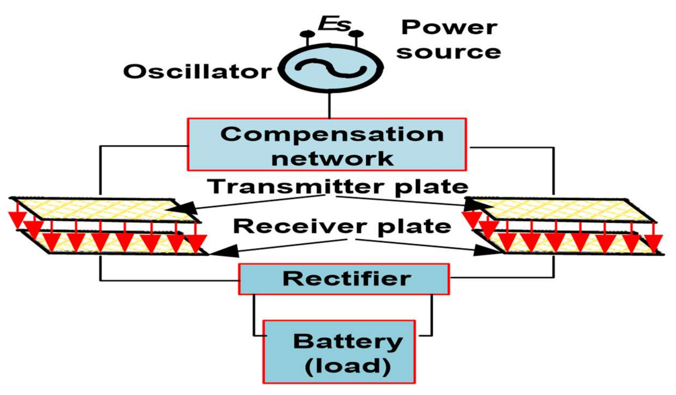
As illustrated in
Figure 1, the transmitter/primary plate can be energized using a higher frequency inverter and appropriate compensation anatomy. Which is implemented to acquire charging more effective. The receiver/secondary plate becomes energized based on electrostatic induction. An appropriate rectifier circuit topology is employed to transform the AC power to the desired DC output for charging the associated battery. The efficiency and the power transfer density are enhanced by increasing the frequency of the power source in the primary circuit or increasing the capacitance value. Since the power transfer density is directly proportional to the value of operating frequency as well as capacitance values.
One of the key benefits of capacitive coupling is different from inductive coupling, it does not require ferrite cores. So reduced weight, reduced losses result in higher power density at a lower cost. Generally, the ICT power density is higher than the 1 in CPT. It works well with high frequencies, so a more compact size and higher power densities.
The drawback of this technology is that it produces an electric field that can interact with most of the materials, containing the human body because of dielectric polarization. Insinuating other material near the vicinity of the plates will cause serious aberration in power transfer and the presence of the human body near the plates will cause excessive exposure to electromagnetic fields leading to serious health issues. For this reason, CPT is usually employed in low-power applications.
In electric transportation, capacitive charging can be employed on road in a transverse configuration as shown in
Figure 2. This configuration consists of two plates, i.e., the transmitter/primary as well as receiver/secondary plate. The primary plate is capacitively coupled with the receiver plate and energized by an oscillator in the opposite phase (180 degrees) using a high alternating voltage [
24]. An alternating electric field induces an alternating voltage of the opposite phase in the receiver plate. The receiver is terminated to the battery through a rectifier [
25,
26]. For efficient charging, there should be a proper alignment of both plates.
In the longitudinal configuration, either the transmitter or the receiver plate will be the active electrode. For the return path of the current, the ground electrode is the large passive electrode that is used between the passive as well as active electrodes. The transmitter oscillator and the load are connected between the active and passive electrodes. The introduction of alternating charge displacement in the loaded dipole through electrostatic induction is initiated by the transmitter oscillator.
To transfer power at the kW level, several efforts have been made. An efficiency of 90.1% has been reported in [
27] at a power of 1034 W at 200 kHz frequency. In the double-sided LCLC topology, a power of 2.4 kW has been transferred based on the efficiency of 90.8% at a switching frequency of 1 MHz [
28]. An improved topology is given in [
29], in which the number of switching components has been reduced from 10 to 8, and an efficiency of 95.87% is achieved from the same power level and switching frequency. In the modified LLC topology [
30], an efficiency of 94% was obtained from the power of 1 kW at a switching frequency of 250 kHz. In [
21], capacitive charging through bumper by employing cylindrical capacitive plates for 1 kW charging with operating at a frequency of 540 kHz at an efficiency of 83% is illustrated. The [
20] presents the CPT through multiple phase-shifted capacitive plates for and reduces the fringing effect as well field focusing.
2.2. Inductive Charging
Inductive charging employs the concept of transformer action, i.e., mutual induction [
31,
32,
33] between the primary/transmitter and the secondary/receiver coil. In
Figure 3, the transmitter coil is placed on the track whereas the receiver coil is implanted in the EV chassis. The transmitter coil is energized by a high-frequency converter. Due to the magnetic coupling between the coils, the receiver coil is energized through mutual induction [
34]. By employing a proper rectifier circuit, the AC is converted to DC and fed into the associated load or battery source. To transfer low power, usually, an electronic oscillator is used to generate high-frequency AC. Inductive charging is one of the most popular wireless charging methods nowadays and it is accepted widely; even Tesla Model 3 employs inductive charging which is still under development phase. A lot of research has already been carried out in this section in the last decade. A novel inductive coupler acquiring 97% efficiency at 8.3 kW output power with the air gap of 3 mm at 100 kHz is presented in [
35] and proved that the distance between the coils can be enhanced to make charging automatic. Through inductive charging, one can charge vehicles maintaining the air gap up to a few centimeters.
The charging distance can be increased by using proper power electronics compensation technology without affecting the power level [
16,
36]. The only disadvantage of using this method is that it operates at a low frequency up to 100 kHz to limit the losses in the ferrite core, which rises the system size. In addition, the efficiency will be poor due to losses in the ferrite core. Efficiency can be increased through proper shielding and field focusing techniques, but it will eventually increase its cost and size. Proper compensation topology is required to make charging more efficient. The OLEV project has discerned that at a frequency of 20 kHz, the high-power transfer efficiency is 83% for a power level of 60 kW with a 20 cm air gap and 24 cm lateral tolerance [
37,
38].
Various category of charging coil pads is now being proposed [
39] to make charging more efficient such as bipolar pads, circular pads, and DD-Q pads (for the control of current in double D coil ‘DD’ as well as in the quadrature ‘Q’ coil independently, that permits the overall coupler to be tuned and dependent on all kind of geometry used as the transmitting coil), and H-shaped pads. For circular pads, there is poor coupling between the transmitter and the receiver pads, because the flux path height is nearly one-fourth of its diameter. So, a circular pad of a larger dimension is adopted to obtain high power transfer efficiency. However, this makes the design impractical. However, newer bipolar pads which have almost the same performance indices as DD-Q pads have 25% lesser copper content [
40].
3. Survey Data Analysis and Comparison Based on Data Obtained
Recently, several novelties have been proposed and the data has been summarized for Inductive Power Transfer (IPT) in
Table 1 and Capacitive Power Transfer (CPT) in
Table 2, respectively. These tables show the recent advancements and development in the electric vehicle charging domain. In future research, this data can be used for the development of a more effective prototype.
The comparative analysis based on efficiency, power/volume ratio, power, power/coupler area ratio, frequency, air gap distance, etc. are given below. COMSOL simulation has been used to study the effect of gap distance () on output power and frequency, and the effect of frequency over output power.
Table 3 provides the survey of wireless EV charging infrastructure allocation in various organizations. Above, comprehensive survey providing a way to optimize the wireless charging solutions and their feasibility enhancement. The primary aim of this state-of-the-art is to support the wireless charging EVs in practical scenarios, which further promotes the promising novel wireless WPT in a real-time setup. On the other hand, these research work has achieved significant substantial achievements, but still there is adequate to be examined feasibility before CPT technologies comes to practical setups. Thus, there are three key research directions for WPT enhancement: highly efficient coupler shape with compact size to enhance the density, to mitigate the adverse impact of higher switching frequencies and to improve the safety requirements of CPT system in practical design.
3.1. Output Power vs. Gap Distance
Figure 4, illustrates the variation of output power with a length of the gap for two different efficiencies 100%, 80%, 70%, 60% and 40%, In this
Figure 4, the circle indicating the IPT while the square shape indicates the CPT. Moreover, the color of shape represents the efficiency such as green color for 100% (
n = 1), orange color for 80% (
n = 0.8), purple color for 70% and 60% (
n = 0.6), blue for 40%, respectively.
From
Figure 4, we can see that IPT has higher efficiency for air gap range of 0.1 cm to 10 cm, in the power level domain 1 kW to 10 kW. IPT has low efficiency for small gap length, i.e., (distance < 0.1 cm) [
64]. CPT has high efficiency for all power levels for gap length less than 0.001 cm.
3.2. Efficiency vs. Frequency
Figure 5 shows the variation of efficiency with respect to frequency (in kHz). IPT shows a moderate efficiency in the range of 60% to 80% for a wide frequency range. For IPT, it has been observed that at medium frequencies, i.e., from 10 kHz to 500 kHz, it shows higher efficiency but increasing its frequency above the range it causes a drop in efficiency due to the constraints of power electronics circuitry. Whereas in the case of CPT, it is observed as frequency increases its efficiency also increases while the coupler area decreases. Thus, it is clear from
Figure 5 that CPT operates efficiently at high frequencies, i.e., from 100 kHz to 1500 kHz.
3.3. Output Power/Area vs. Frequency
For both IPT and CPT, with an increase in the coupler area 1 and 2, respectively, power transfer also increases. From
Figure 6, it can be deduced that output power/area is comparable for all the frequency range for IPT whereas in CPT, it is comparable only for higher frequencies, i.e., from 500 s of kHz to 10 s of MHz.
3.4. Frequency vs. Gap Distance
Figure 7 shows the plot of frequency v/s gap distance for IPT (circle) and CPT (triangle). It can be seen that IPT performs well at medium frequencies, i.e., from 10 kHz to 500 kHz for gap distance in the range 1 cm to 1000 cm while CPT requires high frequencies, i.e., from 500 kHz to 10 MHz for low gap distance, i.e., (<0.1 cm). This proves that “CPT operates more efficiently at comparably higher frequencies at smaller air gap distances whereas IPT operates efficiently at larger air gap distances at a wide range of medium frequencies”.
3.5. Output Power vs. Coupler Volume
The coupler area denotes the receiver area. The coupler volume is the product of air gap distance and coupler area. For both IPT and CPT, output power increases with an increase in the coupler area, considering an increase in the air gap distance depicted to in
Figure 8.
Since coupler volume is a product of two quantities, i.e., coupler area and air gap distance, likewise its variation depends on the variation of the two:
Both quantities increase by some amount.
The former quantity increases by a larger amount as compared to the latter which decreases by a smaller amount, and vice versa.
Table 4 demonstrating the comparative analysis between IPT and CPT based on the practical parameters.
4. Comparison among Different Geometries of Plates
In this section, the effect of the geometry of the plates on the power transfer efficiency has been studied through computer simulation using COMSOL software. To acquire a fair comparison, the same proportions such as gap distance, area and dielectric medium are considered. It is performed to analyze for the geometries having the least fringing field strength to lie in the safety standards [
80]. The above simulation is performed for a separate capacitive module. This also performed to analyze if the geometries have some impact on changing the power losses or power transfer density.
The distance of air gap is remained fixed at 0.5 cm. Different plate shapes have been analyzed such as triangle, rectangle, pentagon, hexagon, heptagon and octagon. Dimensions of all plates are kept accordingly to acquire a constant area of 25 cm2 for all geometries. The air is used as the dielectric medium between the plates which are made up of copper. A constant voltage of 250 V is impressed on the plates to obtain the results.
The number of electric field lines between the plates is kept constant at 200. The results are given in
Figure 9a–g, from these results, it can be concluded that all geometric shapes except the rectangular plate have a significant fringing effect. So only the rectangular plate has the highest power transfer capacity for a given gap distance.
It can be observed that taking rectangular plates as a reference, as the number of edges is increased and tends towards circular structure, the fringing field strength increases drastically. It can be easily visualized that the number of field lines is directly proportional to the electric field energy (intensity). For all
Figure 9a–g, if the number of field lines is fixed, rectangular plates will have the least field density.
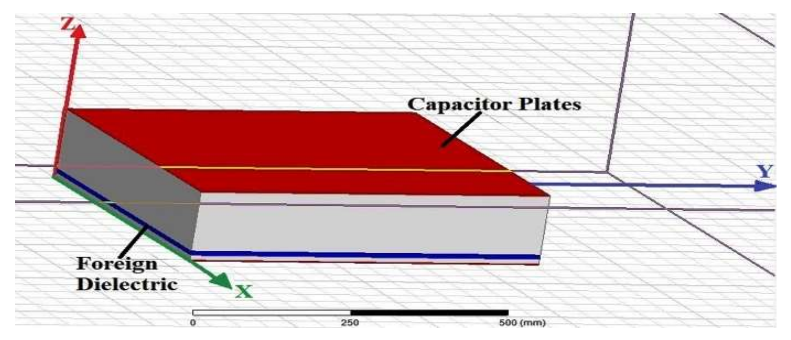
5. Effects of Insertion of Foreign Particles in Single Module CPT System
In this section, the simulation studies (depicted in
Figure 10 and
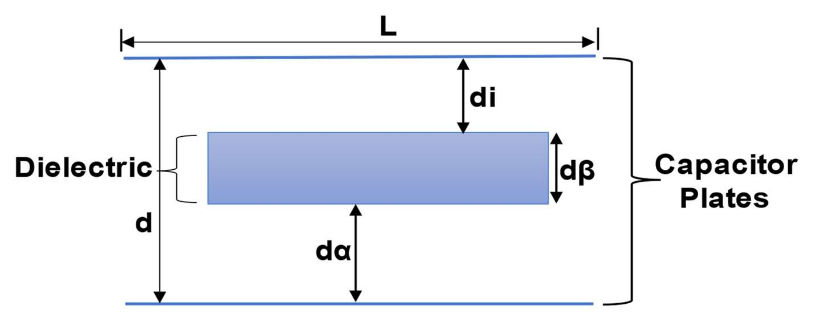
Figure 11) on the effect of inserting foreign particles in the gap between the plates. The thickness of the plate and the air gap is kept constant at 1 mm and 150 mm, respectively. The proportions of plates are (50 × 50 × 1) mm
3 and the width (
dβ) of the proposed foreign object (dielectric) is changed throughout. The overall distance of air gap between the plates is represented by “
d” and the distance of dielectric from the transmitter and receiver plate is represented by
di and
dα, respectively. The mutual capacitance (
) value is determined using the empirical Formula (1).
In the absence of a foreign object, i.e., (
) the capacitance is constant. For a foreign object or dielectric (
), the capacitance rising with
. By using the ANSYS Maxwell software, primary, secondary and coupling capacitance values can be simulated at various thicknesses of the related dielectric medium based on the constant parameters. These parameters comprise air gap distance (
d), plate dimension and distance from the transmitter plate (
di). The
. values are taken for five distinct materials namely aluminum (al), polyethylene (poly), PVC, glass and high-density polyethylene (hdpe). Generally, the respective relative permittivity as 4–10, 1–3.4, 2.7, 2.25 and 8.2, respectively. The plot of
v/s thickness of the foreign material for these five different materials has been plotted in
Figure 12.
From
Figure 12, it is visible that the
increases with the thickness of the dielectric medium. If the capacitance value is rising, then it has an effect on the resonance of the proposed charging circuit topology, eventually that will disturb the power transfer and slow down the overall charging process.
6. Effects of Insertion of Foreign Particles in Two Module CPT System
In this section, the investigation is carried out on a two-module based CPT system. Since, the directly proportional to the width of the foreign particles at that instant and relative permittivity of the proposed medium, respectively.
In
Figure 13, the capacitance of plate (P
1, P
2 refer to primary capacitance and P
3, P
4 refer to secondary capacitance), closer the proximity of dielectric to the plates (P
1, P
2 or P
3, P
4) more will be the corresponding plates capacitance. The primary, as well as secondary capacitance values, can be raises along with an increment in dielectric object between these plates. Thus, the secondary capacitance value substantially raises than the primary capacitance value due to dielectric was incorporated near to the secondary plates. We have concluded that a dielectric foreign object and a horizontal capacitance coupler raises the coupling capacitance.
The capacitances can be significantly increased if the area of the foreign object is higher eventually which can affect the total power transferred due to there is a disturbance in the resonance circuit. In the experimental case study, if a parallel plate capacitor is linked to a similar side of the that is a case study of LCLC based compensation topology, resulting in raised of equivalent self-capacitance. The relative change is triggered and lowered by add-on the foreign or metallic object, so that the effect of resonance will be reduced.
To solve the issue of the impact of a foreign object or dielectric, a suitable circuit can be employed that can just achieve by analyzing the susceptibility of proposed system enhancement to acquire variation in the system parameters. For a horizontal capacitive coupler, there is a smaller size metallic foreign object which is not affecting the average working of the proposed CPT system referred from
Figure 14. However, a larger size of a metallic foreign object in between the 2 pairs of plates. These larger sizes metallic foreign object having a substantial impact on the coupling capacitances as well as the subsequent working process of the proposed CPT system.
Figure 15 and
Figure 16 demonstrate that self-capacitance (primary and secondary) increasing with permittivity as well as dielectric thickness of the foreign objects. Since it is closer to secondary plates, secondary self-capacitance is increased more significantly.
Figure 17 illustrates that the mutual capacitance is increased with the dielectric thickness of the proposed foreign object. In addition, the relative permittivity increasing with increment in mutual capacitance.
7. Effects of Adding Ceramic Coating
Ceramic as a dielectric can easily be used to enhance the capacitance between the charging plates and hence improve the overall charging efficiency. It can be introduced in the charging system by spraying a coat of it on the charging plates. The analysis is carried out in this section with varying thickness of the ceramic coating, i.e., from 0.0 to 1.0 mm with a step of 0.1 mm thickness. The relative permittivity is taken as 6000.
The simulation results are given in
Figure 18a–f, The results obtained illustrate that upon increasing the thickness of the ceramic coating, the actual capacitance, as well as the energy transfer density across the two plates keeps on increasing. If we observe the energy transfer density at thickness 0.0 mm, it comes out to be 0.0110 J/m
3. However, if we expand the thickness of the coating to 0.5 mm, then the value of the same increases by 1.5 times to 0.0170 J/m
3, Furthermore, if we consider the maximum coating thickness of 1.0 mm, then the energy transfer density obtained is 0.0305 J/m
3 which thrice the value at no coating.
One more important consideration is that the characteristics of the system are not changing at a drastic level for the coating thickness 0.0 to 0.5 mm, but it shows an appreciable change for the range 0.5 to 1.0 mm. The whole scenario can easily be understood with the help of the corresponding graphs for energy transfer density, capacitance and the ratio of energy transfer density obtained theoretically and practically v/s the coating thickness as shown in
Figure 19. The above simulation analysis will be utilized in our experimental setup so we can obtain appropriate values of parameters that can be used for creating a better and highly efficient charging environment A general conclusion can be drawn from the above analysis is as the capacitance increases with the increases in thickness of ceramic coating it affects the resonance of the charging environment which eventually causes disturbance in the charging, So it is mandatory to perform an experimental analysis and define what thickness of ceramic should be used for highly efficient charging.
Apart from its functional advantages, the ceramic coating can also entertain some aesthetic values. Its application leads to the protection of the plate from oxidation by UV rays as the charging plates are bound to be left outside in the sun. It also provides the plate with some chemical resistance against chemical stains and etching. Due to these protective qualities, this technology is currently being used to protect the exterior of cars. Even though the coating has these advantages, there are still a few drawbacks. The ceramic coating will increase the overall production cost, and with ageing it becomes brittle. Overall, the experimental analysis shows that it is beneficial to add a layer of coating (say 1 mm because it’s practical) to increase the charging effectiveness of the proposed wireless charging of EVs.
8. Effects of Naturally Occurring Materials on Charging Track Pads
Another study that can be made in the wireless charging system of vehicles is the incorporation of certainly occurring materials such as sand as well as water for charging phenomena (referred in
Figure 20,
Figure 21 and
Figure 22). This can be employed through the advancement of a specifically designed lanes. On the other hand, these materials are the barrier to effective EV charging, while in-depth study of the same displays various distinct results.
Direct incorporation of these materials in this study is not feasible. However, this can be achieved by adjusting the proportion of similarity between these plates. The study has been performed by using the proposed three basics naturally occurring materials such as sand, water and air. A layer comprising these materials in a certain proportion which is presented between the thickness and the plates that are changed from 0.0 mm to 1.0 mm. In addition, three factors (energy transfer density, efficiency and capacitance), are evaluated with the change in the coating thickness. The thickness is varied in 10 steps with each step incrementing 0.1 mm to the thickness.
8.1. For Dry Sand
At 0.0 mm coating, here the energy transfer density is 0.0100 J/m3 and the relative permittivity is assigned as 4. In addition, we are rising the coating thickness to 0.5 mm and rising this value by 1.2 times to 0.0127 J/m3. Furthermore, if we rise the material thickness to 1.0 mm, then the value reaches the maximum value of 0.0157 J/m3 which is more than 1.5 times the original value without the implication of the sand layer. This tells us that the presence of sand on the charging plate only increases its effectiveness and not hinders the process.
8.2. For Wet Sand
At 0.0 mm coating, here the energy transfer density is 0.0110 J/m3. The relative permittivity is assigned as 24. In addition, we are rising the coating thickness to 0.5 mm the value rises by 1.3 times to 0.0133 J/m3. Furthermore, when we rise the thickness to 1.0 mm, then these value reaches the maximum value of 0.0167 J/m3 which is more than 1.6 times the original value without the implication of the wet sand layer. This tells us that the presence of wet sand also has the same effect on the charging system however, the characteristics are a bit amplified in this case as compared to the dry sand.
8.3. For Water Layer
At 0.0 mm coating, here the energy transfer density is 0.0110 J/m3. The relative permittivity is assigned as 80. Its incidence can be implemented by manually spraying the track with water. In addition, we rise the coating thickness value to 0.5 mm and the value raises by 1.3 times to 0.0134 J/m3. Furthermore, if we rise the thickness to 1.0 mm, then the related value reaches the maximum value of 0.0170 J/m3 which is 1.7 times the original value without the implication of the water layer. This interprets as the presence of water has the most desirable effect on the charging system among the three elements.
The main notion that comes out is that these naturally occurring elements would lead to desirable changes in the wireless charging system. This can easily be understood based on the plots given in the
Figure 23,
Figure 24 and
Figure 25. For the mixture of air and sand, air and water and air and moisture sand between the capacitive charging tracks, the capacitance can be obtained through simulation.
To transfer power efficiently without affecting the resonance of the circuit, proper limits should be decided so that its value of capacitance should not be unusual from its set value because if it happens, then it will cause fluctuations in energy transfer that is not appropriate for the charging system. Since the values of the power transfer density is not that pervasive than that of the combinations involving the elements in their pure form, so these situations need to be avoided because it will ultimately affect the overall efficiency of the systems.
For the mixture of air and sand, air and water and air and moisture sand between the capacitive charging tracks, the capacitances obtained are 7.08 pF, 8.74 pF and 9.24 pF, respectively. The above simulations show an appreciable result as compared to the ones where we are taking the elements in their pure form. Since it is not affecting our overall charging system, it’s replenishing the capacitance so obtained.
To transfer power efficiently without affecting the resonance of the circuit, proper limits which will be explained and utilized in the future experimental analysis that its value of capacitance should not be aberrant from its prescribed value because if it happens, it will cause fluctuations in energy transfer which is not sustainable for the charging system. That will eventually demand further improvisation. In
Figure 26, the energy density so obtained from the appropriate combinations is 0.0177 J/m
3, 0.2185 J/m
3 and 0.0231 J/m
3.
Since, the values of the power transfer density (referred from
Figure 27) are not that pervasive than that of the combinations involving the elements in their pure form. So, these situations need to be avoided because they will ultimately impact the overall effectiveness of the proposed system.
9. Conclusions
The aim of the paper was an in-depth analysis of the two wireless charging systems, i.e., IPT and CPT. Through simulation studies, it is demonstrated that in the case of IPT, above 500 Hz, efficiency decreases while it is opposite with CPT. Another observation is that CPT is more efficient if the air gap is low and frequency high. Whereas IPT shows higher efficiency, if the air gap is high and frequency is medium. The FEM simulation of various geometries, namely circular, triangular, rectangular, pentagon, hexagon, heptagon and octagon are conducted. The quantities such as capacitance and energy transfer density are calculated and analyzed. The results demonstrate that the rectangular plates have the least fringing, so it is efficient.
The effects of foreign particles between the two capacitor plates of a single-module CPT system are studied. The materials taken are aluminum, glass, PVC, HDPE and polyethylene and their effectiveness are found out to be in the same order. The effect of these foreign particles is most prominent when the thickness is between 3–4 mm. A double-module CPT system that shows the variation in primary and secondary capacitance is presented. The former shows almost no variation, constant-like characteristics while in the case of the latter, aluminum leads the group with better scores of capacitances and energy transfer density.
The effects of ceramic coating on the inside of the capacitor plates and the variation of capacitance and energy transfer density with thickness. The result comes out to be the same as that of the insertion of foreign particles, i.e., positive. It is further appended by replacing the ceramic coating with naturally occurring substances such as water, sand and wet sand. It is carried out to replicate different weather conditions such as storm, rains and dust particles.
Author Contributions
Conceptualization, M.T. and M.S. (Mohd Shahvez); formal analysis, M.T. and M.S. (Mohd Shahvez); funding acquisition, C.-H.L., M.T., B.A. and A.A.; investigation, M.T., M.A. and M.S. (Mohd Shahvez); methodology, M.A., M.T. and M.S. (Mohd Shahvez); supervision, M.T.; writing—original draft, M.A., M.T., M.S. (Mohd Shahvez) and M.S. (Mobashshir Siddiqui); writing—review and editing, C.-H.L., B.A., A.A. and A.R.B. All authors have read and agreed to the published version of the manuscript.
Funding
This research was funded in part by the Taif University Researchers Supporting Project Number (TURSP-2020/278), Taif University, Taif, Saudi Arabia and in part by the Ministry of Science and Technology, Taiwan, R.O.C., grant number (MOST 110-2221-E-011-081, MOST 110-2622-E-011-004.)
Institutional Review Board Statement
This article does not contain any studies with human participants /animals performed by any of the authors.
Informed Consent Statement
Not applicable.
Data Availability Statement
Does not contain any third-party data, data analyzed or generated during this study are included in this manuscript.
Acknowledgments
The authors would like to acknowledge the financial support from Taif University Researchers Supporting Project Number (TURSP-2020/278), Taif University, Taif, Saudi Arabia. The authors also acknowledge the support provided by the Hardware-In-the-Loop (HIL) Lab, Department of Electrical Engineering, Aligarh Muslim University, India by project grant number CRGS/MOHD TARIQ/02. The authors sincerely appreciate support from the Taiwan Building Technology Center from The Featured Areas Research Center Program within the framework of the Higher Education Sprout Project by the Ministry of Education in Taiwan.
Conflicts of Interest
The authors declare no conflict of interest.
References
- Qiu, C.; Chau, K.; Liu, C.; Chan, C. Overview of wireless power transfer for electric vehicle charging. In Proceedings of the 2013 World Electric Vehicle Symposium and Exhibition (EVS27), Barcelona, Spain, 17–20 November 2013; pp. 1–9. [Google Scholar]
- Wu, H.H.; Gilchrist, A.; Sealy, K.; Israelsen, P.; Muhs, J. A review on inductive charging for electric vehicles. In Proceedings of the 2011 IEEE International Electric Machines & Drives Conference (IEMDC), Niagara Falls, ON, Canada, 15 May–18 May 2011; pp. 143–147. [Google Scholar]
- Wu, H.H.; Gilchrist, A.; Sealy, K.D.; Bronson, D. A High Efficiency 5 kW Inductive Charger for EVs Using Dual Side Control. IEEE Trans. Ind. Inform. 2012, 8, 585–595. [Google Scholar] [CrossRef] [Green Version]
- Lukic, S.; Pantic, Z. Cutting the Cord: Static and Dynamic Inductive Wireless Charging of Electric Vehicles. IEEE Electrif. Mag. 2013, 1, 57–64. [Google Scholar] [CrossRef]
- Kalwar, K.A.; Aamir, M.; Mekhilef, S. Inductively coupled power transfer (ICPT) for electric vehicle charging—A review. Renew. Sustain. Energy Rev. 2015, 47, 462–475. [Google Scholar] [CrossRef] [Green Version]
- Stamati, T.-E.; Bauer, P. On-road charging of electric vehicles. In Proceedings of the 2013 IEEE Transportation Electrification Conference and Expo (ITEC), Detroit, MI, USA, 16–19 June 2013; pp. 1–8. [Google Scholar]
- Bosshard, R.; Kolar, J.W. Inductive power transfer for electric vehicle charging: Technical challenges and tradeoffs. IEEE Power Electron. Mag. 2016, 3, 22–30. [Google Scholar] [CrossRef]
- Kurs, A.; Karalis, A.; Moffatt, R.; Joannopoulos, J.D.; Fisher, P.; Soljačic, M. Wireless Power Transfer via Strongly Coupled Magnetic Resonances. Science 2007, 317, 83–86. [Google Scholar] [CrossRef] [Green Version]
- Li, S.; Li, W.; Deng, J.; Nguyen, T.D.; Mi, C.C. A Double-Sided LCC Compensation Network and Its Tuning Method for Wireless Power Transfer. IEEE Trans. Veh. Technol. 2014, 64, 2261–2273. [Google Scholar] [CrossRef]
- Lu, F.; Zhang, H.; Mi, C. A Two-Plate Capacitive Wireless Power Transfer System for Electric Vehicle Charging Applications. IEEE Trans. Power Electron. 2017, 33, 964–969. [Google Scholar] [CrossRef]
- Dai, J.; Ludois, D.C. A Survey of Wireless Power Transfer and a Critical Comparison of Inductive and Capacitive Coupling for Small Gap Applications. IEEE Trans. Power Electron. 2015, 30, 6017–6029. [Google Scholar] [CrossRef]
- Culurciello, E.; Andreou, A.G. Capacitive Inter-Chip Data and Power Transfer for 3-D VLSI. IEEE Trans. Circuits Syst. II Express Briefs 2006, 53, 1348–1352. [Google Scholar] [CrossRef]
- Shmilovitz, D.; Abramovitz, A.; Reichman, I.; Abramovitz, A.; Reichman, I. Quasi Resonant LED Driver with Capacitive Isolation and High PF. IEEE J. Emerg. Sel. Top. Power Electron. 2015, 3, 633–641. [Google Scholar] [CrossRef]
- Liu, C.; Hu, A.P.; Nair, N.-K.C. Coupling study of a rotary Capacitive Power Transfer system. In Proceedings of the 2009 IEEE International Conference on Industrial Technology, Victoria, Australia, 10–13 February 2009; pp. 1–6. [Google Scholar]
- Yilmaz, G.; Dehollain, C. Capacitive detuning optimization for wireless uplink communication in neural implants. In Proceedings of the 5th IEEE International Workshop on Advances in Sensors and Interfaces IWASI, Bari, Italy, 13–14 June 2013; pp. 45–50. [Google Scholar] [CrossRef]
- Jegadeesan, R.; Agarwal, K.; Guo, Y.; Yen, S.-C.; Thakor, N.V. Wireless Power Delivery to Flexible Subcutaneous Implants Using Capacitive Coupling. IEEE Trans. Microw. Theory Tech. 2017, 65, 280–292. [Google Scholar] [CrossRef]
- Wang, K.; Sanders, S.; Sanders, S. Contactless USB A capacitive power and bidirectional data transfer system. In Proceedings of the 2014 IEEE Applied Power Electronics Conference and Exposition—APEC 2014, Fort Worth, TX, USA, 16–20 March 2014; pp. 1342–1347. [Google Scholar]
- Mostafa, T.M.; Muharam, A.; Hattori, R. Wireless battery charging system for drones via capacitive power transfer. In Proceedings of the 2017 IEEE PELS Workshop on Emerging Technologies: Wireless Power Transfer (WoW), Chongqing, China, 21–22 May 2017; pp. 1–6. [Google Scholar]
- Hu, A.P.; Liu, C.; Li, H.L. A Novel Contactless Battery Charging System for Soccer Playing Robot. In Proceedings of the 2008 15th International Conference on Mechatronics and Machine Vision in Practice, Auckland, New Zealand, 2–4 December 2008; pp. 646–650. [Google Scholar]
- Zhang, H.; Lu, F.; Hofmann, H.; Liu, W.; Mi, C.C. A Four-Plate Compact Capacitive Coupler Design and LCL-Compensated Topology for Capacitive Power Transfer in Electric Vehicle Charging Application. IEEE Trans. Power Electron. 2016, 31, 8541–8551. [Google Scholar]
- Al-Saadi, M.; Al-Gizi, A.; Ahmed, S.; Al-Chlaihawi, S.; Craciunescu, A. Analysis of Charge Plate Configurations in Unipolar Capacitive Power Transfer System for the Electric Vehicles Batteries Charging. Procedia Manuf. 2019, 32, 418–425. [Google Scholar] [CrossRef]
- Lu, F.; Zhang, H.; Hofmann, H.; Mi, C. A CLLC-compensated high power and large air-gap capacitive power transfer system for electric vehicle charging applications. In Proceedings of the 2016 IEEE Applied Power Electronics Conference and Exposition (APEC), Long Beach, CA, USA, 20–24 March 2016; pp. 1721–1725. [Google Scholar]
- Lu, F.; Zhang, H.; Hofmann, H.; Mi, C.C. An Inductive and Capacitive Combined Wireless Power Transfer System With LC-Compensated Topology. IEEE Trans. Power Electron. 2016, 31, 8471–8482. [Google Scholar] [CrossRef]
- Majumdar, A.; Cunningham, J.E.; Krishnamoorthy, A.V. Alignment and Performance Considerations for Capacitive, Inductive, and Optical Proximity Communication. IEEE Trans. Adv. Packag. 2010, 33, 690–701. [Google Scholar] [CrossRef]
- Erfani, R.; Marefat, F.; Sodagar, A.M.; Mohseni, P. Transcutaneous capacitive wireless power transfer (C-WPT) for biomedical implants. In Proceedings of the 2017 IEEE International Symposium on Circuits and Systems (ISCAS), Baltimore, MD, USA, 28–31 May 2017; pp. 1–4. [Google Scholar]
- Camurati, P.; Kyoto-fu, H.B. Device for Transporting Energy by Partial Influence through a Delectric Medum. Available online: https://patentimages.storage.googleapis.com/5e/87/a8/c7c74fe8c29b46/US20090206675A1.pdf (accessed on 27 June 2021).
- Dai, J.; Ludois, D.C. Single Active Switch Power Electronics for Kilowatt Scale Capacitive Power Transfer. IEEE J. Emerg. Sel. Top. Power Electron. 2014, 3, 315–323. [Google Scholar] [CrossRef]
- Lu, F.; Zhang, H.; Hofmann, H.; Mi, C. A Double-Sided LCLC-Compensated Capacitive Power Transfer System for Electric Vehicle Charging. IEEE Trans. Power Electron. 2015, 30, 6011–6014. [Google Scholar] [CrossRef]
- Yao, Y.; Wang, Y. LC/CL Compensation Topology and Efficiency-based Optimization Method for Wireless Power Transfer. IET Power Electron. 2018, 11, 1029–1037. [Google Scholar] [CrossRef]
- Rozario, D.; Azeez, N.A.; Williamson, S.S. A modified resonant converter for wireless capacitive power transfer systems used in battery charging applications. In Proceedings of the 2016 IEEE Transportation Electrification Conference and Expo (ITEC), Busan, Korea, 1–4 June 2016; pp. 1–6. [Google Scholar]
- López-Ramos, A.; Menéndez, J.R.; Pique, C. Conditions for the validity of Faraday’s law of induction and their experimental confirmation. Eur. J. Phys. 2008, 29, 1069–1076. [Google Scholar] [CrossRef] [Green Version]
- Ampere’s Law—Reference Notes. Available online: http://notes.tyrocity.com/amperes-law/ (accessed on 18 August 2019).
- Justin, A. Biot-Savart Law. Int. J. Res. 2015, 2, 2348–6848. [Google Scholar]
- Dashora, H.K.; Bertoluzzo, M.; Buja, G. Reflexive properties for different pick-up circuit topologies in a distributed IPT track. In Proceedings of the 2015 IEEE 13th International Conference on Industrial Informatics (INDIN), Cambridge, UK, 22–24 July 2015; pp. 69–75. [Google Scholar]
- Sakamoto, H.; Harada, K.; Washimiya, S.; Takehara, K.; Matsuo, Y.; Nakao, F. Large air gap coupler for inductive charger. IEEE Int. Magn. Conf. 1999, 35, 3526–3528. [Google Scholar] [CrossRef]
- Hui, S.Y.R. Planar Wireless Charging Technology for Portable Electronic Products and Qi. Proc. IEEE 2013, 101, 1290–1301. [Google Scholar] [CrossRef] [Green Version]
- Anthony, S. World’s First Road-Powered Electric Vehicle Network Switches on in South Korea—ExtremeTech. 2013. Available online: https://www.extremetech.com/extreme/163171worldsfirst-road-powered-electric-vehicle-network-switches-on-in-southkorea (accessed on 12 August 2017).
- Huh, J.; Lee, S.W.; Lee, W.Y.; Cho, G.H.; Rim, C.T. Narrow-Width Inductive Power Transfer System for Online Electrical Vehicles. IEEE Trans. Power Electron. 2011, 26, 3666–3679. [Google Scholar] [CrossRef]
- Vincent, D.; Sang, P.H.; Williamson, S.S. Feasibility study of hybrid inductive and capacitive wireless power transfer for future transportation. In Proceedings of the 2017 IEEE Transportation Electrification Conference and Expo (ITEC), Chicago, IL, USA, 22–24 June 2017; pp. 229–233. [Google Scholar]
- Khalilian, M.; Guglielmi, P. Primary-Side Control of a Wireless Power Transfer System with Double-Sided LCC Compensation Topology for Electric Vehicle Battery Charging. In Proceedings of the 2018 IEEE International Telecommunications Energy Conference (INTELEC), Turino, Italy, 7–11 October 2018; pp. 1–6. [Google Scholar] [CrossRef]
- Laouamer, R.; Brunello, M.; Ferrieux, J.; Normand, O.; Buchheit, N. A multi-resonant converter for non-contact charging with electromagnetic coupling. In Proceedings of the IECON’97 23rd International Conference on Industrial Electronics, Control, and Instrumentation, New Orleans, LA, USA, 9–14 November 2002; Volume 2, pp. 792–797. [Google Scholar]
- Nagatsuka, Y.; Ehara, N.; Kaneko, Y.; Abe, S.; Yasuda, T. Compact contactless power transfer system for electric vehicles. In Proceedings of the 2010 International Power Electronics Conference—ECCE ASIA, Sapporo, Japan, 21–24 June 2010; pp. 807–813. [Google Scholar]
- Ning, P.; Onar, O.; Miller, J. Genetic algorithm based coil system optimization for wireless power charging of electric vehicles. In Proceedings of the 2013 IEEE Transportation Electrification Conference and Expo (ITEC), Detroit, MI, USA, 16–19 June 2013; pp. 1–5. [Google Scholar]
- Onar, O.; Miller, J.M.; Campbell, S.; Coomer, C.; White, C.P.; Seiber, L.E. A novel wireless power transfer for in-motion EV/PHEV charging. In Proceedings of the 2013 Twenty-Eighth Annual IEEE Applied Power Electronics Conference and Exposition (APEC), Long Beach, CA, USA, 17–21 March 2013; pp. 3073–3080. [Google Scholar]
- Mecke, R.; Rathge, C. High frequency resonant inverter for contactless energy transmission over large air gap. In Proceedings of the 2004 IEEE 35th Annual Power Electronics Specialists Conference, Aachen, Germany, 20–25 June 2004; Volume 3, pp. 1737–1743. [Google Scholar]
- Kurschner, D.; Rathge, C. Contactless energy transmission systems with improved coil positioning flexibility for high power applications. In Proceedings of the 2008 IEEE Power Electronics Specialists Conference, Rhodes, Greece, 15–19 June 2008; pp. 4326–4332. [Google Scholar]
- Valtchev, S.; Borges, B.; Brandisky, K.; Ben Klaassens, J. Resonant Contactless Energy Transfer with Improved Efficiency. IEEE Trans. Power Electron. 2009, 24, 685–699. [Google Scholar] [CrossRef]
- Lee, S.-H.; Lorenz, R.D. Development and Validation of Model for 95%—Efficiency 220-W Wireless Power Transfer Over a 30-cm Air Gap. IEEE Trans. Ind. Appl. 2011, 47, 2495–2504. [Google Scholar] [CrossRef]
- Imura, T.; Okabe, H.; Hori, Y. Basic experimental study on helical antennas of wireless power transfer for Electric Vehicles by using magnetic resonant couplings. In Proceedings of the 2009 IEEE Vehicle Power and Propulsion Conference, Dearborn, MI, USA, 7–10 September 2009; pp. 936–940. [Google Scholar]
- Basnayaka, C.M.W.; Jayakody, D.N.K.; Sharma, A.; Wang, H.-C.; Muthuchidambaranathan, P.; Kaur, K. Performance Study of Strongly Coupled Magnetic Resonance. arXiv 2019, arXiv:1908.02541. [Google Scholar]
- Karalis, A.; Joannopoulos, J.; Soljačić, M. Efficient wireless non-radiative mid-range energy transfer. Ann. Phys. 2008, 323, 34–48. [Google Scholar] [CrossRef] [Green Version]
- Calder, R.J.; Lee, S.-H.; Lorenz, R.D. Efficient, MHz frequency, resonant converter for sub-meter (30 cm) distance wireless power transfer. In Proceedings of the 2013 IEEE Energy Conversion Congress and Exposition, Denver, CO, USA, 15–19 September 2013; pp. 1917–1924. [Google Scholar]
- Ghahary, A.; Cho, B.H. Design of transcutaneous energy transmission system using a series resonant converter. IEEE Trans. Power Electron. 1992, 7, 261–269. [Google Scholar] [CrossRef]
- Joung, G.; Cho, B. An energy transmission system for an artificial heart using leakage inductance compensation of transcutaneous transformer. In Proceedings of the PESC Record. 27th Annual IEEE Power Electronics Specialists Conference, Baveno, Italy, 23–27 June 1996. [Google Scholar]
- Choi, B.; Nho, J.; Cha, H.; Ahn, T.; Choi, S. Design and Implementation of Low-Profile Contactless Battery Charger Using Planar Printed Circuit Board Windings as Energy Transfer Device. IEEE Trans. Ind. Electron. 2004, 51, 140–147. [Google Scholar] [CrossRef] [Green Version]
- Sample, A.; Meyer, D.T.; Smith, J.R. Analysis, Experimental Results, and Range Adaptation of Magnetically Coupled Resonators for Wireless Power Transfer. IEEE Trans. Ind. Electron. 2011, 58, 544–554. [Google Scholar] [CrossRef]
- Jang, Y.; Jovanovic, M. A contactless electrical energy transmission system for portable-telephone battery chargers. In Proceedings of the INTELEC. Twenty-Second International Telecommunications Energy Conference, Phoenix, AZ, USA, 10–14 September 2000. [Google Scholar]
- Lee, E.; Huh, J.; Thai, X.; Choi, S.Y.; Rim, C. Impedance transformers for compact and robust coupled magnetic resonance systems. In Proceedings of the 2013 IEEE Energy Conversion Congress and Exposition, Denver, CO, USA, 15–19 September 2013; pp. 2239–2244. [Google Scholar]
- Hui, S.Y.; Chung, H.; Tang, S.C. Coreless printed circuit board (PCB) transformers for power MOSFET/IGBT gate drive circuits. IEEE Trans. Power Electron. 1999, 14, 422–430. [Google Scholar] [CrossRef]
- Waffenschmidt, E.; Staring, T. Limitation of inductive power transfer for consumer applications. In Proceedings of the 13th European Conference on Power Electronics and Applications, Barcelona, Spain, 8–10 September 2009; pp. 1–10. [Google Scholar]
- Budhia, M.; Covic, G.A.; Boys, J.T.; Huang, C.-Y. Development and evaluation of single sided flux couplers for contactless electric vehicle charging. In Proceedings of the 2011 IEEE Energy Conversion Congress and Exposition, Phoenix, AZ, USA, 16–21 September 2011; pp. 614–621. [Google Scholar]
- Wang, C.-S.; Stielau, O.H.; Covic, G. Design Considerations for a Contactless Electric Vehicle Battery Charger. IEEE Trans. Ind. Electron. 2005, 52, 1308–1314. [Google Scholar] [CrossRef]
- Wang, C.-S.; Covic, G.A.; Stielau, O.H. Power Transfer Capability and Bifurcation Phenomena of Loosely Coupled Inductive Power Transfer Systems. IEEE Trans. Ind. Electron. 2004, 51, 148–157. [Google Scholar] [CrossRef]
- Sun, M.; Zhang, Y.P. Performance of inter-chip RF-interconnect using CPW, capacitive coupler, and UWB transceiver. IEEE Trans. Microw. Theory Tech. 2005, 53, 2650–2655. [Google Scholar] [CrossRef]
- Sodagar, A.M.; Amiri, P. Capacitive coupling for power and data telemetry to implantable biomedical microsystems. In Proceedings of the 2009 4th International IEEE/EMBS Conference on Neural Engineering, Antalya, Turkey, 29 April–2 May 2009; pp. 411–414. [Google Scholar]
- Liu, C.; Hu, A.P.; Wang, B.; Nair, N. A Capacitively Coupled Contactless Matrix Charging Platform with Soft Switched Transformer Control. IEEE Trans. Ind. Electron. 2013, 60, 249–260. [Google Scholar] [CrossRef]
- Chao, L.; Hu, A.P.; Xin, D. A contactless power transfer system with capacitively coupled matrix pad. presented at the Energy Conversion Congress and Exposition (ECCE), Phoenix, AZ, USA, 16–21 September 2011; pp. 3488–3494. [Google Scholar]
- Kline, M.; Izyumin, I.; Boser, B.; Sanders, S. Capacitive power transfer for contactless charging. In Proceedings of the 2011 Twenty-Sixth Annual IEEE Applied Power Electronics Conference and Exposition (APEC), Fort Worth, TX, USA, 6–11 March 2011; pp. 1398–1404. [Google Scholar] [CrossRef] [Green Version]
- Liu, C.; Hu, A.; Nair, N.-K. Modelling and analysis of a capacitively coupled contactless power transfer system. IET Power Electron. 2011, 4, 808–815. [Google Scholar] [CrossRef]
- Ludois, D.C.; Erickson, M.J.; Reed, J.K. Aerodynamic Fluid Bearings for Translational and Rotating Capacitors in Noncontact Capacitive Power Transfer Systems. IEEE Trans. Ind. Appl. 2013, 50, 1025–1033. [Google Scholar] [CrossRef]
- Dai, J.; Ludois, D.C. Wireless electric vehicle charging via capacitive power transfer through a conformal bumper. In Proceedings of the 2015 IEEE Applied Power Electronics Conference and Exposition (APEC), Charlotte, NC, USA, 15–19 March 2015; pp. 3307–3313. [Google Scholar]
- Ko, Y.D.; Jang, Y.J.; Lee, M.S. The optimal economic design of the wireless powered intelligent transportation system using genetic algorithm considering nonlinear cost function. Comput. Ind. Eng. 2015, 89, 67–79. [Google Scholar] [CrossRef]
- Deflorio, F.; Castello, L. Dynamic charging-while-driving systems for freight delivery services with electric vehicles: Traffic and energy modelling. Transp. Res. Part C Emerg. Technol. 2017, 81, 342–362. [Google Scholar] [CrossRef]
- Feasibility Analysis and Development of On-Road Charging Solutions for Future Electric Vehicles. Available online: https://www.fabric-project.eu/www.fabric-project.eu/index.html (accessed on 11 March 2021).
- Wireless Charging of Electric Vehicles-Crada Report, Technical Report; Oak Ridge National Laboratory (ORNL): Oak Ridge, TN, USA; National Transportation Research Center (NTRC): Knoxville, TN, USA, 2015.
- Jeong, S.; Jang, Y.J.; Kum, D. Economic Analysis of the Dynamic Charging Electric Vehicle. IEEE Trans. Power Electron. 2015, 30, 6368–6377. [Google Scholar] [CrossRef]
- Möller, C. Carbon Neutral Road Transportation: An Assessment of the Potential of Electrified Road Systems. 2017. Available online: http://www.diva-portal.org/smash/record.jsf (accessed on 8 August 2021).
- Rim, C.T.; Mi, C. Wireless Power Transfer for Electric Vehicles and Mobile Devices. In Wireless Power Transfer for Electric Vehicles and Mobile Devices; IEEE Press: Piscataway, NJ, USA, 2017; pp. 161–208. [Google Scholar]
- Off Road Trials for Electric Highways Technology. OLEV Annual Progress Report (System Division). KAIST OLEV Report 1. 2015. Available online: https://www.gov.uk/government/news/off-road-trials-for-electric-highways-technology (accessed on 21 March 2021).
- IEEE Standards University. Developments in Wireless Power Transfer Standards and Regulations. Available online: http://www.standardsuniversity.org/e-magazine/june-2016/selecteddevelopments-wireless-power-transfer-standards-regulations/ (accessed on 3 January 2017).
Figure 1.
The basic longitudinal capacitive charging.
Figure 1.
The basic longitudinal capacitive charging.
Figure 2.
Block diagram for transverse capacitive charging technique in vehicles.
Figure 2.
Block diagram for transverse capacitive charging technique in vehicles.
Figure 3.
Block diagram for transverse inductive charging technique in vehicles.
Figure 3.
Block diagram for transverse inductive charging technique in vehicles.
Figure 4.
Graph of OUTPUT POWER (w) vs. GAP DISTANCE (cm).
Figure 4.
Graph of OUTPUT POWER (w) vs. GAP DISTANCE (cm).
Figure 5.
Graph of EFFICIENCY (inductive, capacitive) vs. FREQUENCY (in x axis).
Figure 5.
Graph of EFFICIENCY (inductive, capacitive) vs. FREQUENCY (in x axis).
Figure 6.
Graph of OUTPUT POWER/COUPLER AREA (W/cm2) vs. FREQUENCY (kHz).
Figure 6.
Graph of OUTPUT POWER/COUPLER AREA (W/cm2) vs. FREQUENCY (kHz).
Figure 7.
Graph of FREQUENCY vs. GAP DISTANCE (mm).
Figure 7.
Graph of FREQUENCY vs. GAP DISTANCE (mm).
Figure 8.
Graph of OUTPUT POWER vs. COUPLER VOLUME (mm3).
Figure 8.
Graph of OUTPUT POWER vs. COUPLER VOLUME (mm3).
Figure 9.
(a) Simulation of octagon plate geometry in COMSOL. (b) Simulation of heptagon plate geometry in COMSOL. (c) Simulation of hexagon plate geometry in COMSOL. (d) Simulation of circular plate geometry in COMSOL. (e) Simulation of pentagon plate geometry in COMSOL. (f) Simulation of rectangular plate geometry in COMSOL. (g) Simulation of triangular plate geometry in COMSOL.
Figure 10.
A dielectric foreign object in a single module CPT system in ANSYS MAXWELL environment.
Figure 10.
A dielectric foreign object in a single module CPT system in ANSYS MAXWELL environment.
Figure 11.
A Dielectric foreign object in a single module capacitive based CPT system.
Figure 11.
A Dielectric foreign object in a single module capacitive based CPT system.
Figure 12.
Variation of capacitance with dielectric thickness (mm).
Figure 12.
Variation of capacitance with dielectric thickness (mm).
Figure 13.
A dielectric foreign object in a two-module CPT system.
Figure 13.
A dielectric foreign object in a two-module CPT system.
Figure 14.
A dielectric foreign object in a single module CPT system in ANSYS Maxwell. Environment.
Figure 14.
A dielectric foreign object in a single module CPT system in ANSYS Maxwell. Environment.
Figure 15.
Primary capacitance.
Figure 15.
Primary capacitance.
Figure 16.
Secondary capacitance.
Figure 16.
Secondary capacitance.
Figure 17.
Mutual capacitance.
Figure 17.
Mutual capacitance.
Figure 18.
(a) Capacitor plate arrangement with ceramic thickness (d = 0.5 mm). (b) Capacitor plate arrangement with ceramic thickness (d = 0.6 mm). (c) Capacitor plate arrangement with ceramic thickness (d = 0.7 mm). (d) Capacitor plate arrangement with ceramic thickness (d = 0.8 mm). (e) Capacitor plate arrangement with ceramic thickness (d = 0.9 mm). (f) Capacitor plate arrangement with ceramic thickness (d = 1 mm).
Figure 19.
(a) Variation of capacitance due to ceramic coating on both plates. (b) Variation of energy transfer density due to ceramic coating on both plates. (c) Variation of ratio% (theoretical obtained energy transfer density by actual electric transfer density) due to ceramic coating on both plates.
Figure 20.
(a) Single module capacitor incorporates with dry sand in ANYSYS Maxwell Simulation. (b) Material electric energy density (for dry sand) with coating thickness of 0 mm. (c) Material electric energy density (for dry sand) with coating thickness of 0.5 mm. (d) Material electric energy density (for dry sand) with coating thickness of 1 mm.
Figure 21.
(a) Single module capacitor incorporates with wet sand in ANYSYS Maxwell Simulation. (b) Material electric energy density (for wet sand) with coating thickness of 0 mm. (c) Material electric energy density (for wet sand) with coating thickness of 0.5 mm. (d) Material electric energy density (for wet sand) with coating thickness of 1 mm.
Figure 22.
(a) Single module Capacitor incorporate with water in ANYSYS Maxwell Simulation. (b) Material electric energy density (for water) with coating thickness of 0 mm. (c) Material electric energy density (for water) with coating thickness of 0.5 mm. (d) Material electric energy density (for water) with coating thickness of 1 mm.
Figure 23.
Variation of ratio of theoretical obtained energy transfer density to the electric transfer density with respect to material thickness.
Figure 23.
Variation of ratio of theoretical obtained energy transfer density to the electric transfer density with respect to material thickness.
Figure 24.
Variation of energy transfer density with respect to material thickness.
Figure 24.
Variation of energy transfer density with respect to material thickness.
Figure 25.
Variation of capacitance with respect to material thickness.
Figure 25.
Variation of capacitance with respect to material thickness.
Figure 26.
(a) Single module capacitor incorporated with mixture of air and sand. (b) Single module capacitor incorporated with mixture of air and water. (c) Single module capacitor incorporated with mixture of sand and water.
Figure 26.
(a) Single module capacitor incorporated with mixture of air and sand. (b) Single module capacitor incorporated with mixture of air and water. (c) Single module capacitor incorporated with mixture of sand and water.
Figure 27.
(a) Energy transfer density of air and sand. (b) Energy transfer density of air and water. (c) Energy transfer density of air, sand and water mixture.
Figure 27.
(a) Energy transfer density of air and sand. (b) Energy transfer density of air and water. (c) Energy transfer density of air, sand and water mixture.
Table 1.
Inductive Power Transfer (IPT).
Table 1.
Inductive Power Transfer (IPT).
| Power (W) | η
(%) | Frequency
(kHz) | Gap
(mm) | Transmitter
Area
(cm2) | Receiver
Area
(cm2) | Coupler
Volume
(cm3) | Power per
Unit Area (W/cm2) | References |
|---|
| 3 k | 89 | 22.95 | 6~8 | ~25 | ~25 | 20 | 120 | [41] |
| 1.5 k | 95 coil | 20 | 70 | 600 | 600 | 4200 | 2.5 | [42] |
| 2 k | 91 | 23.5 | 75 | 1134 | 855~1134 | 8505 | 1.763 | [43,44] |
| 1 k | 90 | 100 | 30~300 | 133~1257 | 133~1257 | 7500 | 2 | [45,46] |
| 315~522 | 75~83 | 90 | 0~2 | ~0.25 | ~0.25 | 0.05 | 1600 | [47] |
| 220 | 95 coil | 3.7 MHz | 300 | 908 | 908 | 27,240 | 0.242 | [48] |
| 100 | 97 coil | 15.9 MHz | 200 | 707 | 707 | 14,140 | 0.141 | [49] |
| 60 | 40 | 9.9 MHz | 2000 | 2827 | 2827 | 565,400 | 0.0213 | [50,51] |
| 50 | 80 | 3.5 MHz | 300 | 1257 | 1257 | 3771 | 0.0397 | [52] |
| 48 | 72~76 | 53~123 | 20 | 37 | 37 | 74 | 0.037 | [53,54] |
| 24 | 68 | 950 | 2.4 | 9.08 | 9.08 | 2.179 | 2.643 | [55] |
| 12 | 50 | 7650 | 700 | 2734 | 2734 | 191,380 | 4.84 × 10⁻³ | [56] |
| 4.5 | 60~70 | 65~140 | 1.5 | 6.24 | 6.24 | 0.936 | 0.721 | [57] |
| 1.2 | 40 | 500 | 130 | 314 | 314 | 4082 | 3.80 × 10⁻³ | [58] |
| 1 | - | 1 MHz | 1.54 | 1 | 1 | 0.154 | 1 | [59,60] |
| 7 k | - | 20 | 125 | 3200 | 3200 | 40,000 | 2.13 | [61] |
| 300 k | - | 20 | 45 | 4800 | 4800 | 21,600 | 6.25 | [62,63] |
Table 2.
Capacitive Power Transfer (CPT).
Table 2.
Capacitive Power Transfer (CPT).
| Power (W) | η
(%) | Frequency
(kHz) | Gap
(mm) | Transmitter
Area
(cm2) | Receiver
Area
(cm2) | Coupler Vlume
(cm3) | Power per Unit Area (W/cm2) | References |
|---|
| 0.0008 | - | 15 | 0.008 | 8.1 × 10⁻⁵ | 8.1 × 10⁻⁵ | 6.48 × 10⁻⁸ | 9.87 | [64] |
| 0.001~0.1 | - | 250~18,000 | 0.1~1 | 6.25 | 6.25 | 0.625 | 0.008 | [65] |
| 1.6 | 54 | 449 | 0.5 | 50 | 50 | 2.5 | 0.032 | [66,67] |
| 3.7 | 80 | 4200 | 0.13 | 6 | 6 | 0.078 | 0.616 | [68] |
| 7.6 | 41 | 840 | 0.5 | 100 | 100 | 5 | 0.076 | [69] |
| 100 | 94 | 848 | 0.125 | 2413 | 2011 | 30.1623 | 0.0414 | [70] |
| 1021 | 83 | 540 | 0.25 | 2000 | 2000 | 50 | 0.5105 | [71] |
Table 3.
Practical allocation of wireless EV charging infrastructure.
Table 3.
Practical allocation of wireless EV charging infrastructure.
| Practical Setup/Demos | Distance of Charging Route
(in km) | Number of Wireless EVs in Operation | Targeted
Vehicle, Types, and Operational Facilities | Battery Storage Capacity (in kWh) | Charging
Power
(in kW) | References |
|---|
| Seoul grand park, South Korea | 2.2 | 3 | Trolly service (demo and CPT/IPT testing phase) | 100 | 100 | [72] |
| Polito solution, Italy | 0.70 | testing phase | Track development (research phase) | testing phase | 20 | [73] |
| Vedecom, France | 0.10 long track and 0.2 paved lanes | 2 | Micro (research phase) | testing phase | 20 | [74] |
| APEEMF, Tennessee state, USA | - | testing phase | Dynamic wireless charging (CPT/IPT research phase) | testing phase | 2.2 (six coil with track) | [75] |
| Gumi buses setup transient, South Korea | 32 | 4 | Transit buses service (testing phase) | 100 | 100 | [76] |
| Lommel, Belgium | 1.2 | 1 | Transit buses service (testing phase) | testing phase | 40–80 | [77] |
| University of Malaga, Spain | dynamic charging 0.1 long | 1 | Gulliver vehicle: U520 ESP (IPT testing phase) | 20 | 50 (two inductive charging infrastructure) | [78] |
| KAIST, South Korea | 3.76 | 5 | Shuttle buses service (CPT/IPT development phase) | 100 | 60 | [79] |
Table 4.
Various practical parameters based on the Inductive and capacitive power transfer.
Table 4.
Various practical parameters based on the Inductive and capacitive power transfer.
| Parameter | Inductive Power Transfer (IPT) | Capacitive Power Transfer (CPT) |
|---|
| Efficiency | Comparably high [45]
Greater than or up to 90% | Comparably high [70]
Greater than or up to 90% |
| Power Scalability | W to kW | W to kWConstrained by charge surface area |
| Frequency of Operation | <500 kHz [47] | Varies from 500 kHz to 10’s MHz [68] |
| Cost Points | Micro and Coils | Electrode, Amplifier and Transformer |
| Size and Weight | Bulky due to expensive coils | Light in weight due to the absence of coils |
| Power Frequency Product | 10-fold increment in the past 10 years | 10-fold increment in the past 10 years |
| Position Dependency | Two dimensional | Two dimensional |
| Cost | Higher due to complex windings and ferrites | Lower due to plates |
| Range | Efficiently up to 10’s cm | <1 mm [68] |
| EMI Radiation Losses | Yes, scattered due to coil | No, confined within the plates |
| Publisher’s Note: MDPI stays neutral with regard to jurisdictional claims in published maps and institutional affiliations. |
© 2021 by the authors. Licensee MDPI, Basel, Switzerland. This article is an open access article distributed under the terms and conditions of the Creative Commons Attribution (CC BY) license (https://creativecommons.org/licenses/by/4.0/).


 ,
, 


