Article

Counter-Current Suspension Extraction Process of Lignocellulose in Biorefineries to Reach Low Water Consumption, High Extraction Yields, and Extract Concentrations

Hamburg University of Technology, TUHH, Institute of Thermal Separation Processes, Eißendorfer Straße 38, 21073 Hamburg, Germany
*
Author to whom correspondence should be addressed.
Processes 2021, 9(9), 1585; https://doi.org/10.3390/pr9091585
Submission received: 6 August 2021 / Revised: 27 August 2021 / Accepted: 2 September 2021 / Published: 4 September 2021
(This article belongs to the Special Issue Recent Advances in Biorefining Processes)

Abstract

:
The processing of large quantities of water in biorefining processes can lead to immense costs for heating, evaporation, and wastewater disposal. These costs may prohibit the exploitation of alternative products, e.g., xylooligosaccharides from straw, which are regarded as too costly. A new counter-current extractions method is proposed that aims at low solvent (water) consumption, as well as high yields and extract concentrations. This process was evaluated with suspension extraction experiments with steam pretreated wheat straw and the process window analysis based on a mass balance for a washing and a leaching scenario. The latter was conducted with two other suspension extraction processes as a comparison. The equilibration time was found to be well below 10 min. While the suspension extraction with and without recycling need to be designed to achieve a high yield or a high concentration and low solvent consumption, the proposed extraction method can reach all three simultaneously. Thus, this new process is evaluated as a potential method to spare water and downstream costs and allow new processing pathways in second-generation biorefineries.

1. Introduction

Solid–liquid extractions play an essential role in biorefining processes. They can be applied to remove the substrate’s contaminants or gain a product after (pre-) treatment. In both applications, solvent consumption, most often water, is a significant concern. Low water consumption will not allow a high extraction yield. Enormous water will dilute the product and cause further problems. In general, processing large quantities of water leads to space-consuming vessels, pumping capacity demand, heat demand to reach the process temperature and evaporation of dilute streams, and high wastewater costs. Recycling the excess water will be costly or even not feasible. The improvement of solid–liquid extraction processes can reduce operating costs and valorize the biomass constituents in more profitable pathways. This work proposes a new counter-current, solid–liquid extraction process that aims to reach high extractions yields, high extract concentrations, low solvent consumption, and small space demand.
Solid–liquid extractions used to remove contaminants, also called washing, are investigated for many materials and processes. For bioethanol production, the washing of lignocellulosic materials was investigated with animal bedding as a potentially cheaper substrate as opposed to fresh straw [1,2]. Moreover, straw washing before autohydrolysis pretreatment can improve product yields by removing ash [3,4]. The washing of straw biogas digestate for further use in biorefineries or fiber-based materials [5] is discussed. Furthermore, washing the substrate before pretreatment helps remove ash, fines, non-structural carbohydrates, and other contaminants that may be unwanted in the subsequently produced extract, e.g., for the purification of xylooligosaccharides [6]. Contaminants can be particulate or water-soluble as in animal manure, fermentation residues, non-structural substances, or soil.
In contrast to washing, solid–liquid extraction designed to gain a product from a solid is also called leaching. The type of processes regarded here is pretreatment of lignocellulose followed by leaching to produce an extract rich in hemicellulose-derived components. The remaining solids are hydrolyzed to dissolved glucose and solid lignin. These hemicellulose-rich extracts can be used as a substrate for fermentation to a variety of products [7,8], the conversion to furfural [9,10,11,12], and the purification of components such as xylooligosaccharides [6]. Often, separate hemicellulose and glucose valorization pathways are deemed too expensive. Thus, an efficient extraction process is regarded as an enabling technology for the process discussed above. In industrial biorefineries, hemicellulose extraction is avoided. Instead, the pretreated material is enzymatically treated in whole slurry hydrolysis. A process layout to separate pentose, hexose, and lignin in high yields for separate valorization pathways was proposed in previous studies [13,14]. One central idea to avoid forming inhibitors in the reaction stage is to divide the reaction into two mild steps and leach the dissolved components after the reactors. Here, an efficient leaching process is desired.
In any extraction process, the design parameters and process conditions should be chosen to find a suitable trade-off between the extraction yield on the one hand and the water consumption and extract concentration on the other hand. Often, the extraction yield is prioritized, which is facilitated by increasing the water consumption, thus reducing the extract concentration. This choice has drastic consequences on the downstream processing. After leaching, thin streams increase the heat demand to increase the concentration and capital investment for evaporation stages. This issue is even more relevant for producing pure xylooligosaccharides and fed-batch fermentation, which requires a high carbohydrate concentration.
Lignocellulosic biomass possesses especially challenging properties that need to be considered to design improved extraction processes. These materials’ high porosity [15,16] and low bulk density [14] may lead to voluminous extractors. The cellular structure leads to a high water holding capacity for wheat straw of up to four times its weight, and a long path for solute diffusion from the particle center to the surface. Thus, slow internal mass transport is the result. The fibrous nature of annual lignocellulose and reduced material flowability [15] increases forced transportation demand to avoid bridging in pipes and chutes. Finally, the product concentration on pretreated lignocellulose is relatively low compared to other leaching tasks such as beet sugar processing [16].
The literature on solid–liquid extraction, in general, is vast [17,18,19,20,21,22], but only some types of solid–liquid extraction units are used or considered in biorefinery processing based on annual lignocellulose.
A simple process is the submersion of moist biomass with fresh water in a stirred tank and consequent mechanical dewatering [1]. Recycling a fraction of the extract is discussed [1]. These one-pot extractions with or without recycling can be operated continuously using screw or roll presses or in batch mode using a filter press as a dewatering device. The convective mass transport in submerged and stirred tanks may lead to a low transport residence outside the lignocellulose particles and thus a short time to reach an equilibrium between bulk and intra-particular concentration. However, there is a trade-off between yield and solvent consumption.
The belt extractor is a continuously operated counter-current extractor [17,23,24]. The biomass is transferred to a water-permeable belt and spayed with fluid in several stages. It displaces the fluid adhering to the solids and is collected in different vessels below the belt. The fluid of each belt is spayed on the previous section facilitating a fluid transport counter-current to the solid matter. In addition to the intra-particular mass transport resistance, extra particular mass transport resistances are added. At the numerous particle-particle contacts, the transport from the inside to the outside cannot take place. The active surface area is reduced. Furthermore, the fluid velocity between the particles is rather slow, especially near particle–particle contacts. Thus, the velocity layers are increased significantly, lowering the mass transport rate. The combined internal and external transport residence leads to an enormous extraction time and spacious extractors.
An inclined washing screw with counter-current water flow has been proposed [25], also combined with hydrothermal pretreatment [26,27]. It was found that large amounts of water are required to achieve a measurable extraction performance, and the extract concentrations are low. The poor performance may be attributed to the short contact of water and biomass at each position.
In this work, we propose a new continuous counter-current, solid–liquid extraction process based on two or more stages of suspension extraction in stirred tanks and mechanical dewatering devices, for example, screw presses. This process is designed for lignocellulosic material in biorefinery plants, high extraction yields, high extract concentrations, low solvent consumptions, expansive process windows, low space requirements, and compact design based on widely available equipment. This extraction method is designed to be followed by a continuous screw conveyor reactor equipped with a high-pressure plug screw feeder, dewatering the moist biomass severely. The dewatering and recycling of the filtrate are beneficial for the extraction. The performance of the extraction process was modeled and compared with the suspension extraction processes with and without recycling. The comparison was made for a washing and a leaching scenario. Experimental investigation of the suspension extraction of steam pretreated material was shown to demonstrate the feasibility.

2. Materials and Methods

2.1. Wheat Straw

Cut wheat straw pellets of 1–2 cm length from a local farm in Stelle, Germany, with a moisture content of 9.5 wt %, were used. The composition was determined according to the NREL procedure “Determination of structural carbohydrates and lignin in biomass” [28]. The xylose and arabinose sugars are reported as hemicellulose. The dry matter composition was lignin 27.7 wt %, cellulose 36.0 wt %, hemicellulose 28.0 wt %, and unknown components 18.0 wt %.
Hammer-milled and pelleted wheat straw of the brand “Raiffeisen Bionesto” from a producer in central Germany was used as “ground straw”. The particle sizes were in the range of 1–3 mm. The dry matter composition was lignin 20 wt %, cellulose 32 wt %, hemicellulose 21 wt %, ash 8 wt %, and unknown components 19 wt %.

2.2. Steam Pretreatment in 40 L Reactor

The experimental set-up consisted of the reactor, a removable cartridge with 40 L volume, a steam generator PS200-15 from Stritzel Dampftechnische Geräte GmbH, pressure and temperature sensor at the bottom and top, and a water-cooled condenser.
The cylindrical reactor with an oil heating jacket possessed a bayonet fast closing lit. The top was connected to the steam inlet, the top and bottom were connected to the vapor condenser. The cartridge had an inner diameter of 320 mm and a length of 500 mm. The top and bottom were made of removable metal screens with 250 µm openings.
The biomass was washed with 20.0 kg demineralized water per kilogram of dry mass and pressed in a Wiltec hydro press. The moisture content of less than 66 wt % after pressing was reached. The wet biomass was prepared the same day of the hydrothermal pretreatment and stored in a closed container before usage.
The cartridge, filled with 5.000 kg wet biomass, was loaded into the preheated reactor, which was closed afterward. The reaction mixture was preheated for two minutes by flowing steam slowly in at the top to replace the air to the bottom outlet. Then, the outlet to the condenser was closed, and the steam inlet was opened. After approximately four minutes, the maximal pressure of 10 bar absolute, 180 °C, was reached, and the reaction time of 35 min was started. The steam inlet was closed to stop the reaction, and the two outlets to the condenser were opened. After approximately three minutes, the depressurization was completed, and the cartridge was removed from the reactor.

2.3. Extraction in 10 L Stirred Tank

The mixing time to reach an equilibrium was measured in batch 10 L stirred tank with an anchor stirrer. A total of 3.000 kg deionized water was heated to 70 °C at 150 rpm. After the temperature was reached, pretreated wet wheat straw was added. The dry solids concentration was 2 wt %. Samples were taken after 1, 2.5, 5, 10, 15, 20, 30, and 60 min. Each sample was settled for 30 s; the supernatant was taken and filtered in a 0.02 µm syringe filter to remove particles. The sample was stored at −18 °C until analysis. The concentration of the total pentoses was converted to a dimensionless scale to account for different moisture contents and thus to feed concentrations in the pretreated biomass. The average of the last three concentrations in each experiment was used to define the equilibrium concentration. Here, the equilibrium was defined as the concentration in the bulk that was constant for at least three measurement points. In this state, it was assumed that the particle interior and the bulk phase concentrations were identical, and no further mass transport occurred.

2.4. Analytical Method

The TUHH central laboratory analyzes aqueous samples applying method M03.008 Version 02: “Aqueous samples are centrifuged and directly analyzed by an HPLC system coupled to a refractive index detector to determine free carbohydrates such as cellobiose, glucose, xylose, and arabinose, and degradation products such as HMF and furfural. Bound carbohydrates are extracted with acid hydrolysis (4% H2SO4) beforehand. Separation is performed with an ion exclusion HPLC phase column”. This method is based on the same NREL method as is that in Section 2.3 [28].

2.5. Calculation of Extraction Processes

To investigate the extraction of the new counter-current, solid–liquid extraction method, we calculated the process windows and compared them with two other processes: suspension extraction without recycling and suspension extraction with recycling. Two important design parameters for each process were varied, and the effect on the extract concentration C E in gram solute in 1000 g liquid and the extraction yield Y E in gram solute in extract per gram solute in feed was evaluated. For each extraction vessel, thermodynamic equilibrium was assumed. A washing and a leaching scenario were investigated to account for these possible applications. Mass balance calculations and iterations were performed in Microsoft Excel 2016 using the solver function.
Each scenario was defined by its feed composition. Here, solids, solute, and solvent (water) were considered. The solute was defined as entirely soluble in water. In the washing scenario, water and solute contents were small in order to represent freshly harvested lignocellulose. The solute represented ash, fine particles, and non-structural carbohydrates. The washing feed contained 86.4 wt % solids, 4.5 wt % solute, and 9.1 wt % solvent. The leaching scenario represented steam-pretreated wheat straw. The solute represented soluble hemicellulose-derived components such as oligomeric and monomeric pentoses. The leaching feed contained 25.8 wt % solids, 7.5 wt % solute, and 66.7 wt % solvent.

2.5.1. Suspension Extraction without Recycling
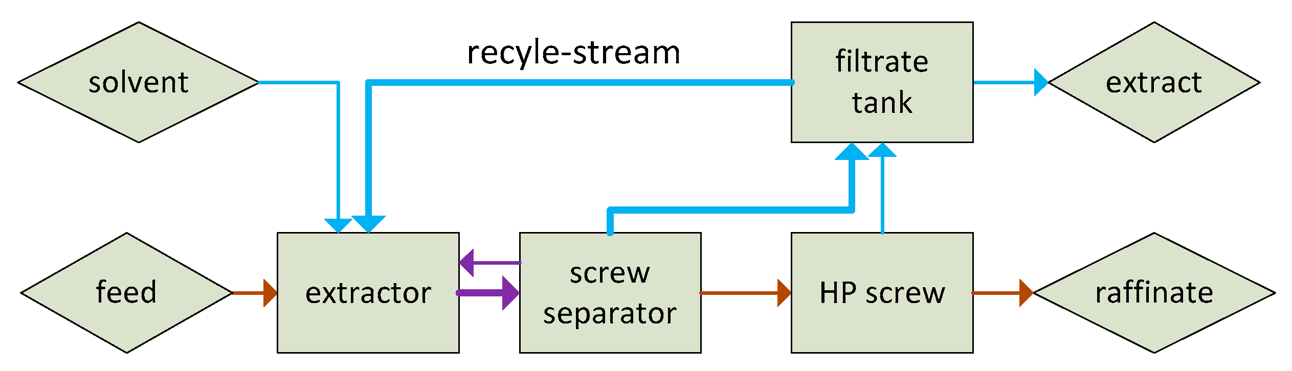
In Figure 1, the block flow diagram of the suspension extraction with and without recycling is displayed. In the extraction process without recycling, the recycling stream was neglected. Feed and solvent (water) were mixed in a continuously stirred tank. The outflowing suspension was pressed in one or two consecutive presses, e.g., screw presses or roll presses. The first one could represent a press near the extraction plant. The second one represented a high-pressure plug screw feeder that dewatered the moist solids while pushing the material into a continuous screw conveyor reactor. A possible presteaming unit to heat the biomass before the input into the reactor, which would be found between the two presses and add a certain amount of water, was neglected. The two presses were considered one press for the calculation since the effluents from both presses were mixed in one filtrate tank.
The first design parameter was the dry matter content in the extraction tank, DM-tank. It was used to determine the water intake. The second parameter was the dry matter content of the pressed material, DM-out. It determined the amount of raffinate leaving the system. The solute mass and concentration were calculated by assuming the same concentrations in the extract and raffinate outflows. The specific solvent consumption L / S in grams of water input to grams of dry solids input was not displayed in the process window.

2.5.2. Suspension Extraction with Recycling

The block flow diagram is represented in Figure 1 and is identical to the extraction without recycling. The recycling stream was determined through the recycling split factor “y”. It was the mass flow ratio of the recycle stream to the filtrate tank inflow. The recycling split factor can take values from 0 to 1. In the case of y = 0, this process was identical to the suspension extraction without recycling. The largest possible value depended on the feed composition and the design parameters to be selected.
The recycling stream was defined as a tear stream to calculate the process by iteration. Initial positive values for the stream amount and concentration were chosen randomly. The water flow to the extractor was calculated on the basis of the dry matter content in the extractor DM-tank, which was set to 5 wt % and not varied in this study. The calculations were executed similarly to those in Section 2.5.1. The recycling split factor was chosen to calculate the recycle flow and concentration. The initially chosen fluid mass flow and solute concentration of the recycle stream were compared with the calculated values and changed to minimize the error calculated as the sum of the squared differences. The extraction yield, the extract concentration, and the solvent consumption are reported.

2.5.3. Counter-Current Extraction

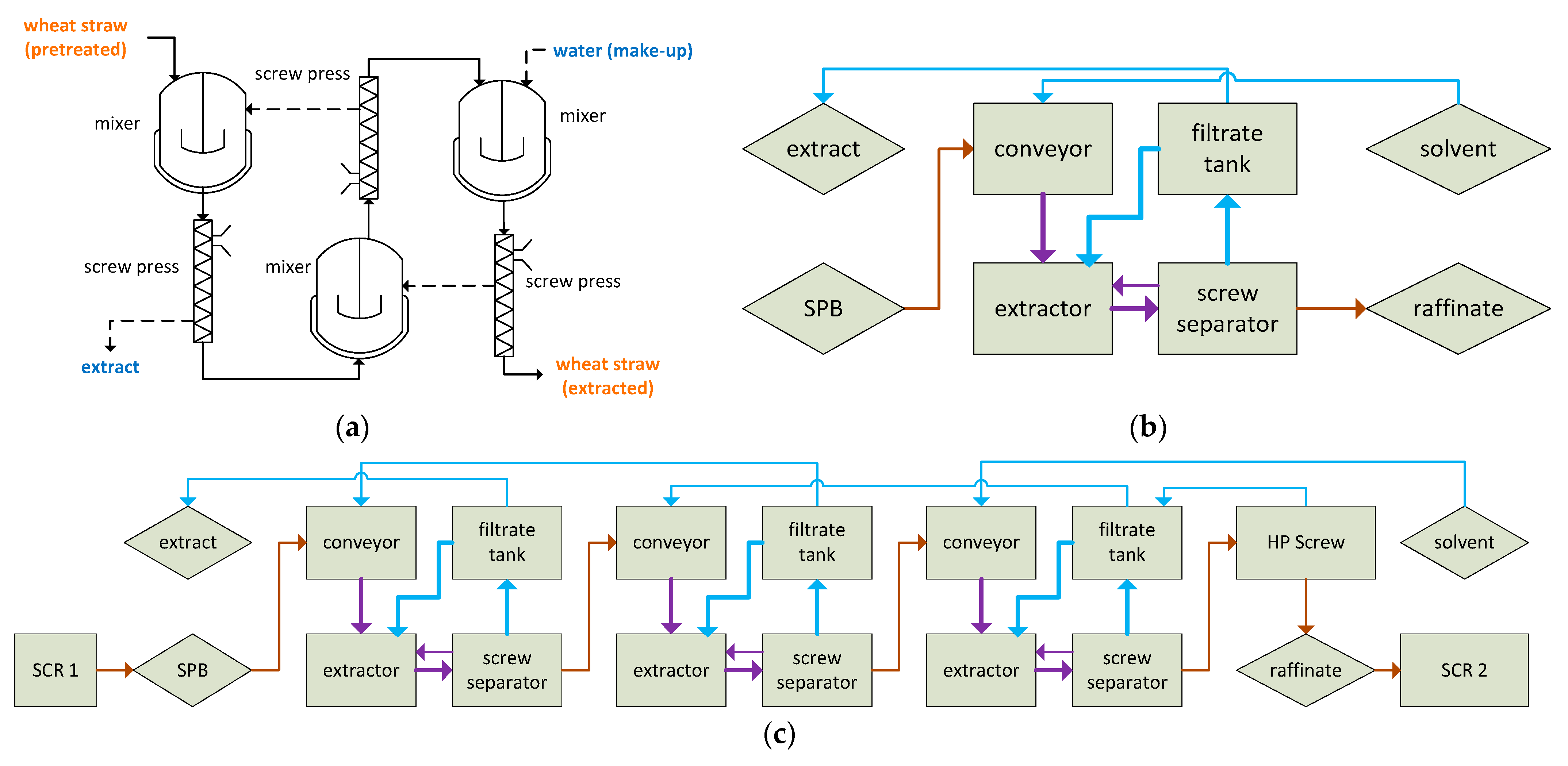
The new counter-current extraction process showed similarities to a mixer-settler extraction process in liquid–liquid extraction systems (see Figure 2a). Solid and liquid phase flow in a counter-current manner through a series of suspension extractors (mixers) and mechanical dewatering devices (settlers) was organized as stages.
To facilitate a low solvent consumption, we recycled the fluid pressed out of the solids, called filtrate, mainly into the extractor, while we fed only a tiny amount of liquid to the next stage (see Figure 2b). A conveyor for the transport of pressed biomass to the next extractor may be required in large plants. In this case, it is suggested that the extract of the next stage is not fed directly to the extractor but the conveyor first. It is regarded as a means to contact the solids with a lower concentrated fluid stream. Therefore, less solute must diffuse from the particle inside to the surface. The conveyor is regarded as optional. Without a conveyor, the wet biomass is transferred directly into the extractor through gravity. To achieve a steady operation of the screw press, we kept the feed tank full at all times by overflowing. The excess amount of suspension was recycled back to the extractor. Additionally, it was a meaningful measure to increase the mixing residence time in a plug flow manner, promoting the achievement of an equilibrium. The residence time distribution in the continuous stirred tank was imperfect in terms of reaching an equilibrium. The filtrate recycle-stream decreased the extract amount fed to the previous stage and allowed for extraction in a suspension similar to the suspension extraction with recycling.
Figure 2c shows the block flow diagram of the extraction process in three stages. Here, it was integrated into a two-step pretreatment approach. The first reactor (SCR 1) produced the steam pretreated lignocellulose leached in the discussed process. The pressed material left the extractor and was pressed further in the second reactor’s high-pressure plug screw feeder (HP screw before SCR 2). The HP screw filtrate was fed to the filtrate tank, while only fresh solvent was fed to the extractor in the last stage. This integration to a high-pressure feeder was beneficial for the extraction process since the pressed out solute could be recovered. In Figure 2d, the exemplary integration of the last stage of the counter-current extraction and the following screw conveyor reactor is shown with 3D symbols.
For the overall mass balance, a component and total mass balance were performed to calculate the flow and composition of the raffinate and the extract, respectively. The overflow input (pure solvent) composition, its amount, and the feed composition were known. Choosing a random extraction yield allowed for the calculation of the solute mass flow in final underflow and overflow.
The stepwise mass balance started at the last stage for the underflow. Here, the underflow output and overflow input were already known from the overall mass balance. The underflow input was known via the screw press moisture content. With the assumption of thermodynamic equilibrium in every stage, the outflowing concentrations of each stage were equal. Thus, the input overflow concentration was equal to the output underflow concentration, which was already known. The missing overflow output was calculated by the stepwise mass balance. This calculation scheme was repeated for the previous stages. For a given stage number, the final overflow concentration must be equal to the overall mass balance’s overflow output (extract). The extraction yield was varied in an iteration to minimize the error, expressed as the square of the stepwise and overall extract concentration difference. Thus, the extraction yield and extract concentration were calculated for a given number of stages and solvent usage.

3. Results

In the following sections, first, the experimental results of the suspension extraction are presented and discussed, and second, the design calculations for suspension extraction with and without recycling and the counter-current suspension extraction are given. The raw data and results can be found in Tables S1–S6 for the modelling results, and in Tables S7 and S8 for the experimental results.

3.1. Batch Suspension Extraction Experiments

The solute mass transport rate from the particle interior to the particle outside is of great importance in an extraction process. The concentration change over time in the bulk phase in a batch suspension extraction was investigated to determine the time to reach the equilibrium concentration for cut and ground pretreated wheat straw. In Figure 3, the total pentose concentration is shown in a dimensionless scale from zero (no solids added) to 100 (equilibrium concentration).
The difference between the two shown samples was the particle size. The ground particles reached 87% of the equilibrium after one minute, while 58% was reached for the larger particles. The ground and coarse samples reached an equilibrium between 1 and 5 min and between 5 and 10 min, respectively.
Smaller particles possess a larger surface area and a shorter average distance inside the particles; thus, mass transfer rates were significantly larger. The oligomer nature of the pentoses after autohydrolysis stream pretreatment and the solute free bulk phase at the beginning of the batch extraction were expected to increase the equilibration time during the suspension extraction. However, the equilibration time was reasonably short for ground particles, which made a continuous extraction feasible. The residence time distribution of a batch extractor and a continuous stirred tank were not comparable. It was assumed that a bulk concentration close to the equilibrium concentration could be achieved by selecting a hydraulic residence time 5 to 10 times greater than the measured equilibrium time in a batch extractor. Therefore, the assumption to reach an equilibrium in the continuous stirred tank suspension extractor in the proposed counter-current extraction was considered feasible. In a continuous stream pretreatment process, the biomass particle size was reduced through the plug screw feeding, similar to a single screw extruder, and the unloading of the reactor, which could be realized as a continuous steam explosion. The composition of the ground pretreated wheat straw was taken as the feed in the leaching scenario.

3.2. Design Calculation for Three Suspension Extraction Processes

In this section, the process windows for the three discussed extraction processes are presented. Here, the process window was the range of the extraction yield Y E and the extract concentration C E that can be achieved by the individually selected design parameters. The design parameters range was chosen as technically possible values on the basis of the authors’ experience. Figure 4 shows the process windows for the three extraction processes and a combined process window for applying the leaching process. Figure 5 displays them in an analog manner for the washing process.
The performance targeted design goal for extraction was to simultaneously reach high extraction yield and extract concentration at a low solvent consumption.

3.2.1. Continuous Suspension Extraction without Recycling

In Figure 4a and Figure 5a, the process windows for the continuous suspension extraction are displayed. The vertical lines refer to the variation in the dry matter content in the tank. As expected, the less the feed was diluted with the solvent, the higher the extract concentration. The near-horizontal lines represent constant values of DM-out. The dry matter content after the pressing DM-out showed no effect on the extract concentration. The drier the material after the press, the higher the extraction yield. The slope of the near-horizontal lines was affected by DM-out. The extraction yield was affected by both design parameters. The dilution of the solids in the tank reduced the raffinate concentration. Thus, the remaining solute in the final underflow—liquid in the pressed solid—was reduced. The dry matter content after pressing determined the amount of solute remaining at the solids in the outflow.
The leaching and the washing case differed in the position of the process window and not in its characteristics. The washing case showed a minor maximal concentration, which was expected to be a consequence of the lower solute amount in the feed. Moreover, a more comprehensive range of extraction yields was possible than in the leaching scenario. This was caused by lower solute content and larger solvent amount in the feed. The solvent consumption was in increasing order of DM-tank: 46, 21, 13, 9, and 6 for the leaching scenario, and 49, 24, 16, 11, and 9 for the washing scenario (compare with the Supplementary Material).

3.2.2. Continuous Suspension Extraction with Recycling

Figure 4b and Figure 5b display the process windows for the continuous suspension extraction with recycling. Here, a dry matter content in the tank was chosen to be 5 wt % and not varied in this study. The dry matter content at the outlet after pressing and the recycling factor were varied to calculate the process window.
The line for a constant recycling rate was vertical at no recycling, and its slope decreased with rising values of the recycling factor itself. The larger the recycling factor at constant DM-out, the larger the concentration, the lower the solvent consumption and the lower the yield. An increase in DM-out improved the extraction yield and extract concentration at the same time if the recycling was larger than zero. Similar to the previous process, the lines for constant DM-out were nearly horizontal, and the slope decreased with decreasing DM-out. When increasing the recycling rate, the lines of constant DM-out were extended towards higher concentrations and lower yields. Changing DM-tank did not affect the position of the lines of constant DM-out but led to a shift of this line along its direction (not shown).
In Figure 6, the effect of the recycling factor is shown on the extraction yield, extract concentration, and solvent consumption for the leaching scenario at DM-tank = 5 wt % and DM-out = 35 wt %. On the one hand, increasing the recycling factor decreased the solvent consumption linearly and increased the extract concentration, which targeted the performance-centered design. On the other hand, an increase in the recycling factor decreased the extraction yield progressively. That meant that the effect on the yield was small for small recycling factors and more significant for larger ones. A recycling factor of 100% was not possible since the water input was larger than the water output adhering to the solids. Thus, some amount of extract needed to be removed from the system. The maximal recycling factor depended on the feed composition and the selected process parameters (not shown).

3.2.3. Counter-Current Continuous Suspension Extraction

In Figure 4c and Figure 5c, the process windows for the continuous counter-current suspension extraction are displayed. The near-vertical lines represent a constant solvent consumption L/S, while the near-horizontal lines represent the number of stages N. The DM-tank did not affect the process windows (not shown). Increasing the number of stages increased the extraction yield and the extract concentration simultaneously, without affecting the solvent consumption. Thus, it became evident that many stages were favorable to reach the performance-centered design criteria. The higher the number of stages, the lower the effect of another stage on the yield and concentration. This effect was more pronounced with an increasing solvent consumption. With an increase in the solvent consumption, the yield was increased, and the extract concentration was decreased. At low solvent consumption, the effect of further stages on yield and concentration remained large.
For this process, the two regarded process parameters can be selected in a wide range of values. Choosing a stage number higher than five did not seem necessary. However, it is possible. For both scenarios, it can be seen that a high yield, high concentration, and low solvent consumption can be achieved with the regarded dry matter contents after pressing.

3.2.4. Comparison of Three Continuous Suspension Extractions

Figure 4d and Figure 5d show the process windows for the three regarded continuous suspension extraction processes. The lines for constant DM-out were identical for the extraction with and without recycling for both scenarios. Thus, recycling a fraction of the extract opened a more extensive process window and allowed for more flexibility in selecting design parameters. Additionally, recycling allowed for achieving substantially larger extract concentrations. Unfortunately, the yield was reduced at the same time. This effect was more pronounced in the leaching scenario than in the washing scenario. A lower DM-tank or a larger recycling factor (>90 wt %) could be chosen to expand the lines of constant DM-out for the suspensions extraction with recycling.
The counter-current extraction process can be found further up and right in the process window diagrams, which means that the extraction yield and the extract concentrations were improved simultaneously. In the counter-current process, the combination of extraction yield and extract concentration was not defined by the DM-out but depended on the number of stages. Moreover, meager solvent consumption was possible with this process, with a comparatively mild decrease in the yield at a constant stage number. In the recycling process, low solvent consumption was possible but with generally worse extraction yields. The yield in the counter-current extraction process was approaching 100%, and concentrations of up to 90 g/1000 g were possible. High performance was possible because the solvent was used to remain a medium but constant concentration difference to the raffinate in each stage. Thus, the underflow concentration was relatively low at the input to the final pressing device. The extract concentration was enriched and approached the feed concentration. The extract concentration can be further improved by choosing a lower solvent consumption and a higher number of stages to compensate for the yield. The limit in yield and concentration were 100 wt % and the feed concentration, respectively.

4. Discussion

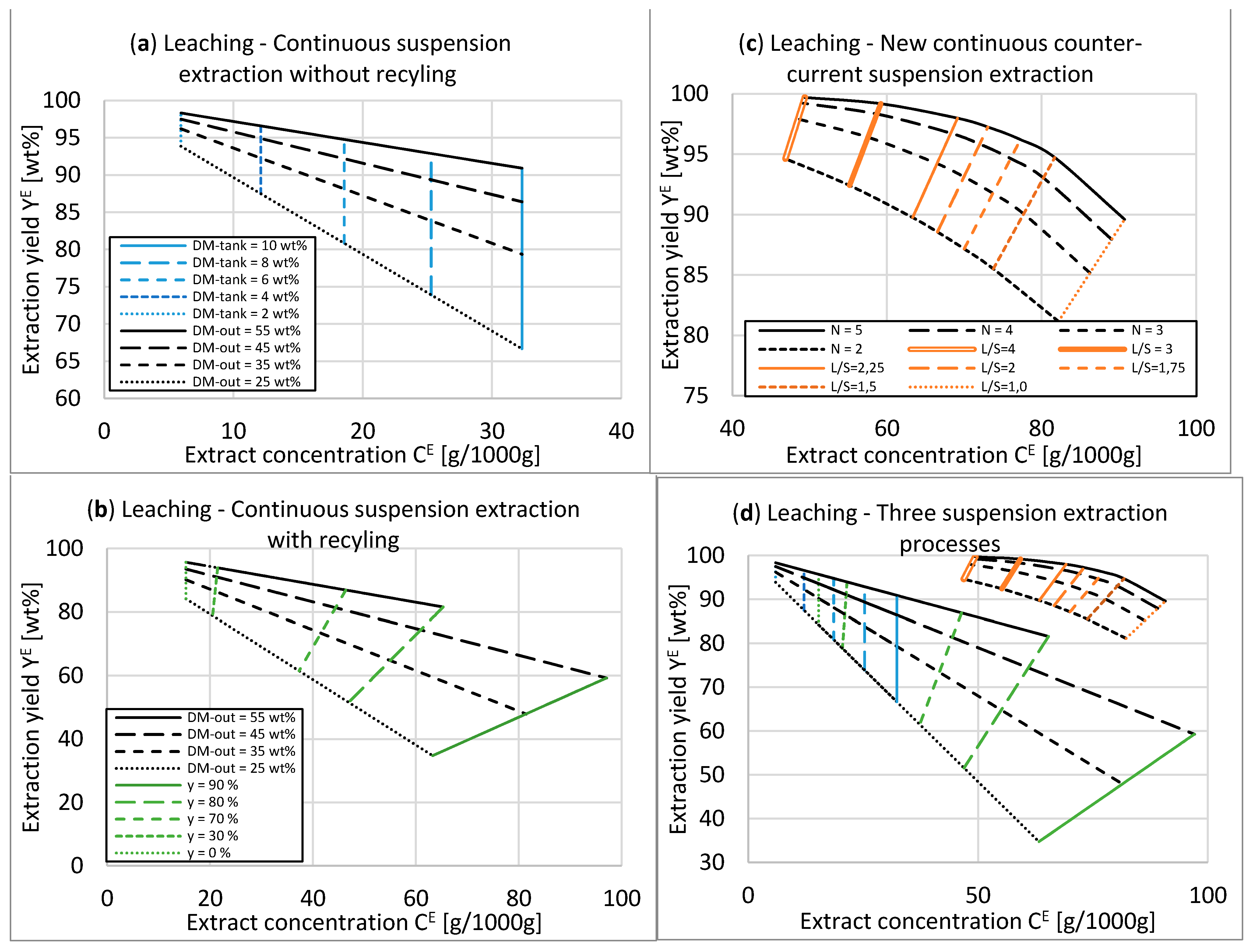
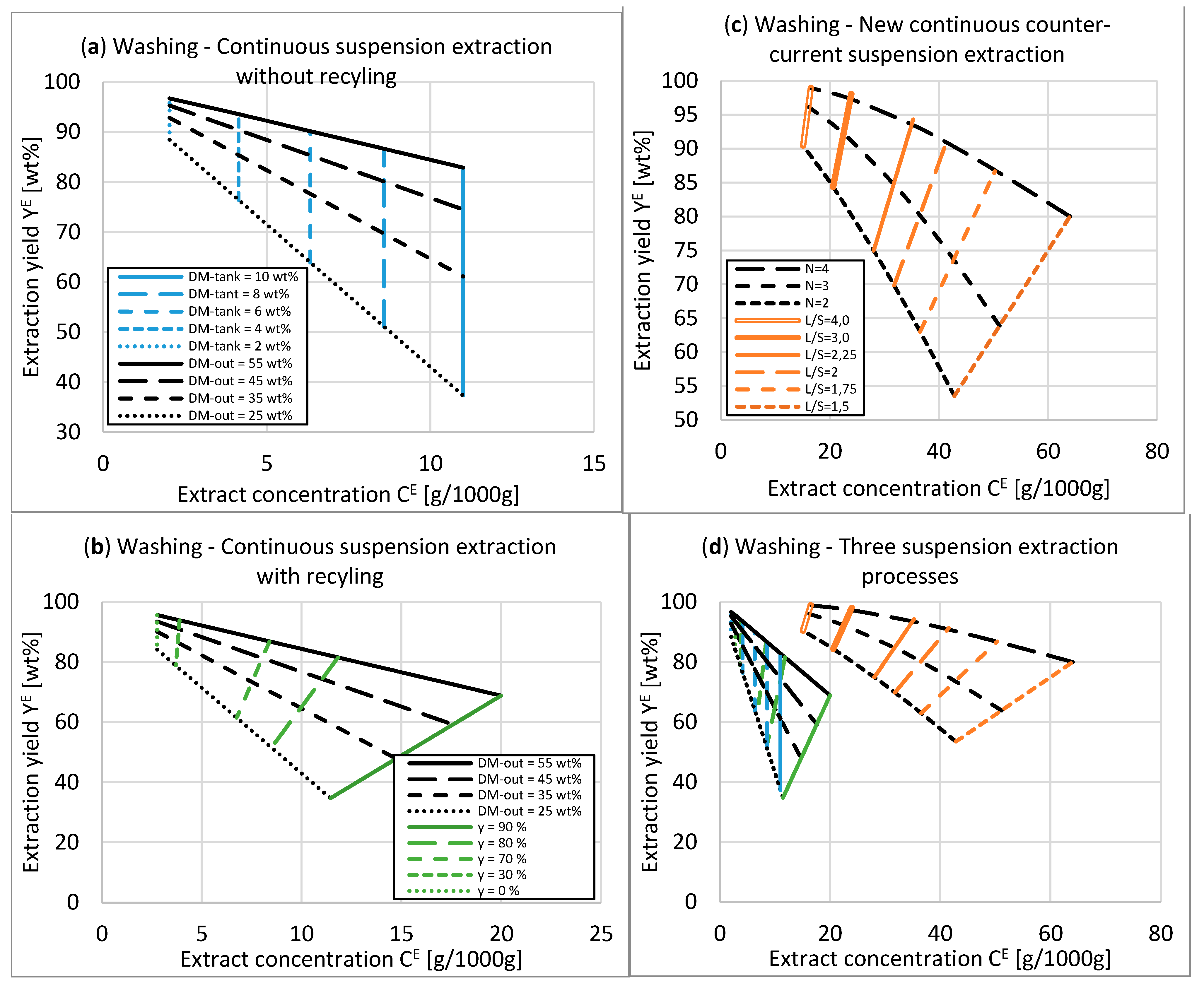
The suspension extraction without recycling possessed low flexibility in the selection of design parameters and extraction performance. Very high extractions yields were possible by a substantial dilution of the extract concentration and enormous solvent consumption. It was not possible to reach concentrations in the extract that were near the feed concentration. However, this process does not require recycling streams; thus, a low effort in the set-up and operation is required.
The suspension extraction with recycling improved flexibility by selecting design parameters from a more comprehensive process window. The advantage of this process is the vastly reduced solvent consumption without a significant increase in the process complexity. Thus, it is suspected that the installation and operational costs are still low. The application for washing and leaching is possible. The application of extreme recycling factors enlarges the process window but is limited by practical constraints. With an increasing recycling factor, the recycling stream increases immensely. A significant reason is that the inflow to the filtrate tank is increased. The amount of liquid recycled at extreme recycling factors becomes a multitude of process solids masses. Additionally, it is challenging to split a stream into two very differently large streams since fluctuations in all streams may be larger than the small outflow. Thus, it is not easy to maintain a steady operation.
It was demonstrated by Sanchis-Sebastiá et al. [1] that suspension extraction with recycling is a feasible approach to wash straw after it is used as animal bedding to gain a straw-rich substrate for the production of bioethanol and one manure-rich stream for bio-methane production. Here, the advantages are an increased concentration for biogas production and reduced demand for costly wastewater treatment. The application is possible due to the moderate requirements for the extraction yield [2].
The process engineer still has to find a trade-off between concentration and extraction yield for the leaching applications. If the two-step pretreatment process is considered, the valuable solute should be removed before further treatment of the solid to avoid product degradation. Thus, a high extraction yield is favored. In this case, there is no significant advantage of the use of a recycling stream.
The continuous counter-current suspensions extraction process proposed in this work allowed us to reach the three desired extraction performance parameters, namely, extraction yield, extract concentration, and low solvent consumption, simultaneously. Thus, this process is favorable for leaching and washing applications over the other two discussed reference processes. Already at two stages, the superiority was shown. There is an extensive range of values for the process parameters that can be chosen; thus, the process can be flexibly adapted to the regarded separation task and processing requirements. An advantage over other counter-current extraction processes is the low solvent consumption and highly concentrated extracts. At the same time, it uses only standard equipment that is widely available and affordable. Furthermore, the spatial arrangement of the plant is flexible, e.g., it can be organized on two or more levels to spare ground area.
A disadvantage is the complexity of the process. The speed of the extraction is achieved by applying external forces in the mixing and pressing. Here, the electrical energy demand must be considered carefully and at best with the help of experiments. The performance and process windows are different for each application and must be evaluated individually. In addition, the screw press must be selected and tested for each material. The throughput, dry matter content in the solids, and the liquid effluent’s fines must be investigated experimentally. The mass of fines in the filtrate may be influenced by the dry matter content in the entrance of the screw press and the rotational speed of the screw. The latter also affects the dry matter content at the outlet and the throughput. As a rule of thumb, the lower the screw speed, the higher the dry matter content of the pressed solids, the lower the throughput, and the lower the content of fines in the filtrate. The amount and size of fines in the filtrate are essential for the plant design. Due to many possible (screw) press configurations and the non-predictable behavior of the feed material, the apparatus size and energy demand require individual process development. The process was not realized experimentally in its entirety. Thus, many essential characteristics remain unknown, such as the stage efficiency, the energy demand for pressing, and the pressing throughput.
The stage efficiency is mainly determined by mass transport in the extractor. Therefore, the assumptions of equilibrium and thus an efficiency of 100% in every stage might not be appropriate in every application. The main parameters affecting the efficiency are the solids loading in the tank; the energy input by stirring; the residence time and residence time distribution in the conveyor, extractor, and piping to the press; and the positions of the extract inlet. If the efficiency was less than 100%, the process windows were not correct. It was suspected that a reduced efficiency and a lower dry matter content after pressing can be compensated by an increase in the number of stages. While the removal of fines in a washing application might be desirable, it may cause the need for additional fines removal, e.g., filtration in the extract before further use.
Overall, this study has shown the favorable characteristics of the newly proposed counter-current, solid–liquid extraction process and points out that the demand for experimental and analytical research is needed. The careful selection of a continuous pressing device and its operational parameters at first and secondly the operation of the entire process is proposed for further investigations. Additionally, the economic effects on the plant-wide cost structure of biorefinery processes through integrating the proposed extraction process can be evaluated with flow sheet models. It would allow the evaluation to which extent the extraction process can improve the economic feasibility for known and new biorefining applications.

5. Conclusions

Suspension extraction was evaluated for use in biorefineries as washing before pretreatment or leaching after pretreatment. The leaching of pretreated wheat straw was shown to be reasonably fast in a suspension extractor. A new continuous counter-current suspension extraction was proposed, and its corresponding process windows were calculated and compared with two co-current reference processes from the literature. It was shown that the new process reached the three design goals simultaneously, and the experiments support the assumptions in the calculation.

6. Patents

A patent application in Luxemburg was submitted on 2 August 2021 with the following title: “PROCESS FOR CONTINUOUS EXTRACTION OF LIGNOCELLULOSIC MATERIAL”. And reference number LU102852.

Supplementary Materials

The following are available online at https://www.mdpi.com/article/10.3390/pr9091585/s1, Table S1: Suspension extraction without recycling. Washing scenario. Table S2: Suspension extraction without recycling. Leaching scenario. Table S3: Suspension extraction with recycling. Washing scenario. Table S4: Suspension extraction with recycling. Leaching scenario. y = recycling factor as a percentage. Table S5: Counter-current suspension extraction. Washing scenario. Table S6: Counter-current suspension extraction. Leaching scenario. Table S7: Experimental data of batch suspensions extraction. Cut pretreated wheat straw. Table S8: Experimental data of batch suspensions extraction. Ground pretreated wheat straw.

Author Contributions

Conceptualization, M.C.; methodology, M.C.; software, M.C.; validation, M.C.; formal analysis, M.C.; investigation, M.C.; resources, I.S.; data curation, M.C.; writing—original draft preparation, M.C. and I.S.; writing—review and editing, M.C. and I.S.; visualization, M.C.; supervision, I.S.; project administration, I.S.; funding acquisition, I.S. All authors have read and agreed to the published version of the manuscript.

Funding

This research was funded by Bundesministerium für Bildung, Wissenschaft und Forschung, grant number Az 031 B 0660 A. The APC was funded by Open Access Publishing.

Institutional Review Board Statement

Not applicable.

Informed Consent Statement

Not applicable.

Data Availability Statement

Data are contained within the article or Supplementary Material.

Acknowledgments

We acknowledge the experimental and analytical support of Mohammad Ali Karimi, Stanislav Parsin, and Timo Steinbrecher. We acknowledge support for the Open Access fees by Hamburg University of Technology (TUHH) in the funding program Open Access Publishing.

Conflicts of Interest

The authors declare no conflict of interest. The funders had no role in the design of the study; in the collection, analyses, or interpretation of data; in the writing of the manuscript, or in the decision to publish the results.

References

  1. Sanchis-Sebastiá, M.; Gomis-Fons, J.; Galbe, M.; Wallberg, O. Techno-Economic Evaluation of Biorefineries Based on Low-Value Feedstocks Using the BioSTEAM Software: A Case Study for Animal Bedding. Processes 2020, 8, 904. [Google Scholar] [CrossRef]
  2. Sanchis-Sebastiá, M.; Erdei, B.; Kovacs, K.; Galbe, M.; Wallberg, O. Introducing Low-Quality Feedstocks in Bioethanol Production: Efficient Conversion of the Lignocellulose Fraction of Animal Bedding through Steam Pretreatment. Biotechnol. Biofuels 2019, 12, 215. [Google Scholar] [CrossRef] [PubMed]
  3. He, Y.; Fang, Z.; Zhang, J.; Li, X.; Bao, J. De-Ashing Treatment of Corn Stover Improves the Efficiencies of Enzymatic Hydrolysis and Consequent Ethanol Fermentation. Bioresour. Technol. 2014, 169, 552–558. [Google Scholar] [CrossRef] [PubMed]
  4. Huang, C.; Wu, X.; Huang, Y.; Lai, C.; Li, X.; Yong, Q. Prewashing Enhances the Liquid Hot Water Pretreatment Efficiency of Waste Wheat Straw with High Free Ash Content. Bioresour. Technol. 2016, 219, 583–588. [Google Scholar] [CrossRef] [PubMed]
  5. Andersen, L.F.; Parsin, S.; Lüdtke, O.; Kaltschmitt, M. Biogas Production from Straw—The Challenge Feedstock Pretreatment. Biomass Conv. Bioref. 2020, 1–24. [Google Scholar] [CrossRef]
  6. Carvalho, A.F.A.; Neto, P.d.O.; da Silva, D.F.; Pastore, G.M. Xylo-Oligosaccharides from Lignocellulosic Materials: Chemical Structure, Health Benefits and Production by Chemical and Enzymatic Hydrolysis. Food Res. Int. 2013, 51, 75–85. [Google Scholar] [CrossRef]
  7. Humbird, D.; Davis, R.; Tao, L.; Kinchin, C.; Hsu, D.; Aden, A.; Schoen, P.; Lukas, J.; Olthof, B.; Worley, M.; et al. Process Design and Economics for Biochemical Conversion of Lignocellulosic Biomass to Ethanol: Dilute-Acid Pretreatment and Enzymatic Hydrolysis of Corn Stover; National Renewable Energy Lab.: Golden, CO, USA, 2011. [Google Scholar]
  8. Larsen, J.; Haven, M.Ø.; Thirup, L. Inbicon Makes Lignocellulosic Ethanol a Commercial Reality. Biomass Bioenergy 2012, 46, 36–45. [Google Scholar] [CrossRef]
  9. Schmidt, L. Wertschöpfungssteigerung aus Lignocellulosen mittels thermisch-enzymatischer Hydrolyse im Hochdruck-Festbett Ökonomische Bewertung am Beispiel von Getreidestroh. Ph.D. Thesis, Technische Universität Hamburg, Hamburg, Germany, 2019. [Google Scholar]
  10. Forstner, J.; Unkelbach, G.; Pindel, E.; Schweppe, R. Heterogen katalysierte Herstellung von Furfural aus Xylose. Chem.-Ing.-Tech. 2012, 84, 503–508. [Google Scholar] [CrossRef]
  11. Schmidt, L.M.; Pérez Martínez, V.; Kaltschmitt, M. Solvent-Free Lignin Recovered by Thermal-Enzymatic Treatment Using Fixed-Bed Reactor Technology—Economic Assessment. Bioresour. Technol. 2018, 268, 382–392. [Google Scholar] [CrossRef] [PubMed]
  12. Gairola, K.; Smirnova, I. Hydrothermal Pentose to Furfural Conversion and Simultaneous Extraction with SC-CO2—Kinetics and Application to Biomass Hydrolysates. Bioresour. Technol. 2012, 123, 592–598. [Google Scholar] [CrossRef] [PubMed]
  13. Conrad, M.; Smirnova, I. Two-Step Autohydrolysis Pretreatment: Towards High Selective Full Fractionation of Wheat Straw. Chem. Ing. Tech. 2020, 92, 1723–1732. [Google Scholar] [CrossRef]
  14. Conrad, M.; Häring, H.; Smirnova, I. Design of an Industrial Autohydrolysis Pretreatment Plant for Annual Lignocellulose. Biomass Conv. Bioref. 2019, 362, 1. [Google Scholar] [CrossRef]
  15. Crawford, N.C.; Nagle, N.; Sievers, D.A.; Stickel, J.J. The Effects of Physical and Chemical Preprocessing on the Flowability of Corn Stover. Biomass Bioenergy 2016, 85, 126–134. [Google Scholar] [CrossRef] [Green Version]
  16. Asadi, M. Beet-Sugar Handbook; Wiley-Interscience: Hoboken, NJ, USA, 2007; ISBN 978-0-471-76347-5. [Google Scholar]
  17. Voeste, T.; Weber, K.; Hiskey, B.; Brunner, G. Liquid–Solid Extraction. In Ullmann’s Encyclopedia of Industrial Chemistry; American Cancer Society, 2006; ISBN 978-3-527-30673-2. Available online: https://onlinelibrary.wiley.com/doi/10.1002/14356007.b03_07 (accessed on 20 August 2021).
  18. Conrad, S. Process of Extraction from Substances Containing Oil, Fat, Etc. U.S. Patent 1,862,945A, 14 June 1932. [Google Scholar]
  19. Appel, G.F.B. Juice Extraction by Hydraulic Displacement. U.S. Patent 3,248,262A, 26 April 1966. [Google Scholar]
  20. Bockisch, M. The Extraction of Vegetable Oils. In Fats and Oils Handbook; Elsevier: Amsterdam, The Netherlands, 1998; pp. 345–445. ISBN 978-0-9818936-0-0. [Google Scholar]
  21. Fellows, P.J. Extraction and separation of food components. In Food Processing Technology; Elsevier: Amsterdam, The Netherlands, 2017; pp. 235–289. ISBN 978-0-08-101907-8. [Google Scholar]
  22. Krotscheck, A.W. Pulp Washing. In Handbook of Pulp; WILEY-VCH Verlag GmbH & Co. KGaA: Weinheim, Germany, 2006; pp. 511–559. ISBN 978-3-527-61988-7. [Google Scholar]
  23. Sievers, D.A.; Tao, L.; Schell, D.J. Performance and Techno-Economic Assessment of Several Solid–Liquid Separation Technologies for Processing Dilute-Acid Pretreated Corn Stover. Bioresour. Technol. 2014, 167, 291–296. [Google Scholar] [CrossRef] [PubMed]
  24. Sievers, D.A.; Kuhn, E.M.; Tucker, M.P.; McMillan, J.D. Effects of Dilute-Acid Pretreatment Conditions on Filtration Performance of Corn Stover Hydrolyzate. Bioresour. Technol. 2017, 243, 474–480. [Google Scholar] [CrossRef] [PubMed]
  25. Kim, K.H.; Tucker, M.P.; Keller, F.A.; Aden, A.; Nguyen, Q.A. Continuous Countercurrent Extraction of Hemicellulose from Pretreated Wood Residues. In Twenty-Second Symposium on Biotechnology for Fuels and Chemicals; Davison, B.H., McMillan, J., Finkelstein, M., Eds.; ABAB Symposium; Humana Press: Totowa, NJ, USA, 2001; pp. 253–267. ISBN 978-1-4612-0217-2. [Google Scholar]
  26. Thomsen, M.H.; Thygesen, A.; Thomsen, A.B. Hydrothermal Treatment of Wheat Straw at Pilot Plant Scale Using a Three-Step Reactor System Aiming at High Hemicellulose Recovery, High Cellulose Digestibility and Low Lignin Hydrolysis. Bioresour. Technol. 2008, 99, 4221–4228. [Google Scholar] [CrossRef] [PubMed]
  27. Thomsen, M.H.; Thygesen, A.; Jørgensen, H.; Larsen, J.; CHRISTENSEN, B.H.; THOMSEN, A.B. Preliminary Results on Optimization of Pilot Scale Pretreatment of Wheat Straw Used in Coproduction of Bioethanol and Electricity. Appl. Biochem. Biotech. 2006, 129, 13. [Google Scholar]
  28. Sluiter, A. Determination of Structural Carbohydrates and Lignin in Biomass: Laboratory Analytical Procedure (LAP). Issue Date: 17 July 2005; 2008; p. 16. Available online: https://www.nrel.gov/docs/gen/fy13/42618.pdf (accessed on 3 September 2021).
Figure 1. Suspension extraction with and without recycling. Diamonds represent streams. Rectangles represent process units. Arrows represent mass flows. Brown: solids, purple: slurry, blue: liquid.
Processes 09 01585 g001
Figure 2. Proposed counter-current solid-liquid extraction process for lignocellulosic material (a) Simplified process scheme of the proposed counter-current solids-liquid extraction process with three stages for the case of pretended wheat straw leaching. Alternating mixing and dewatering units, shown as screw presses, for solid and fluid flow. Solid containing stream (solid arrows). Mainly solid free stream (dashed arrows). (b) Block flow diagram of a single stage of the new counter-current extraction process. Diamonds represent overall input and output flows; steam pretreated biomass (SPB), raffinate, solvent, and extract. Rectangles represent the units of each stage, conveyor (optional) with initial mixing of moist solids and solvent, extractor as a continuous stirred tank, screw separator as mechanical dewatering device, and filtrate tank. Recycle streams are overflow from the screw press feed tank (not shown) back to the extractor and fluid from the filtrate tank to the extractor. (c) Block flow diagram of counter-current solid-liquid extraction with three stages for the usage as leaching process of steam pretreated biomass (SPB). Integration into a two-step autohydrolysis concept, including two screw conveyor reactors (SCR). (d) Graphic representation of the counter-current solids extraction integrated into the subsequent HP screw of the screw conveyor reactor.
Processes 09 01585 g002aProcesses 09 01585 g002b
Figure 3. Dimensionless concentration of total pentoses of a suspension extraction of steam pretreated wheat straw (180 °C, 35 min) in a stirred tank. Solid lines are shown for visual orientation only.
Processes 09 01585 g003
Figure 4. Process windows for the continuous suspension extraction processes for the leaching scenario. (a) Continuous suspension extraction without recycling. (b) Continuous suspension extraction with recycling. (c) New continuous counter-current suspension extraction. (d) All three suspension extraction processes. DM-tank = dry matter content in the extraction tank. DM-out = dry matter content at the stage outlet (press). y = recycling factor. N = number of stages. L/S = liquid to solid ratio (solvent consumption).
Processes 09 01585 g004
Figure 5. Process windows for the continuous suspension extraction processes for the washing scenario. (a) Continuous suspension extraction without recycling. (b) Continuous suspension extraction with recycling. (c) New continuous counter-current suspension extraction. (d) All three suspension extraction processes. DM-tank = dry matter content in the extraction tank. DM-out = dry matter content at the stage outlet (press). y = recycling factor. N = number of stages. L/S = liquid to solid ratio (solvent consumption).
Processes 09 01585 g005
Figure 6. Suspension extraction with recycling for leaching scenario. Extraction yield, extraction concentration, and solvent consumption as a function of the recycling factor. DM-tank = 5 wt % and DM-out = 35 wt %.
Processes 09 01585 g006
Publisher’s Note: MDPI stays neutral with regard to jurisdictional claims in published maps and institutional affiliations.

