Operation Strategy for Electric Vehicle Battery Swap Station Cluster Participating in Frequency Regulation Service


 and
and 
Abstract
:1. Introduction
- The unified model of BSS cluster participating in the FR service is designed and established, which clearly describes the multi-time scale behavior of BSSs. The key items that determine the economic effect are systematically given, including battery degradation costs, power purchase costs, FR service income and battery swap service income.
- The optimization problem constructed in this paper is based on fewer assumptions and is more in line with engineering reality than existing research. Processes such as the battery swap service and FR service are accurately described by only integer variables and linear functions, which can avoid solving complex optimization problems and can obtain more detailed results, including charge and discharge power profiles, SOC, charger plug-in status and battery swap state.
- The index that characterizes the busyness of the battery swap service of BSSs is defined and, in the FR service, the FR power is optimally allocated based on it, which realizes the power support between the BSSs and minimizes the impact of the FR service on the battery swap service.
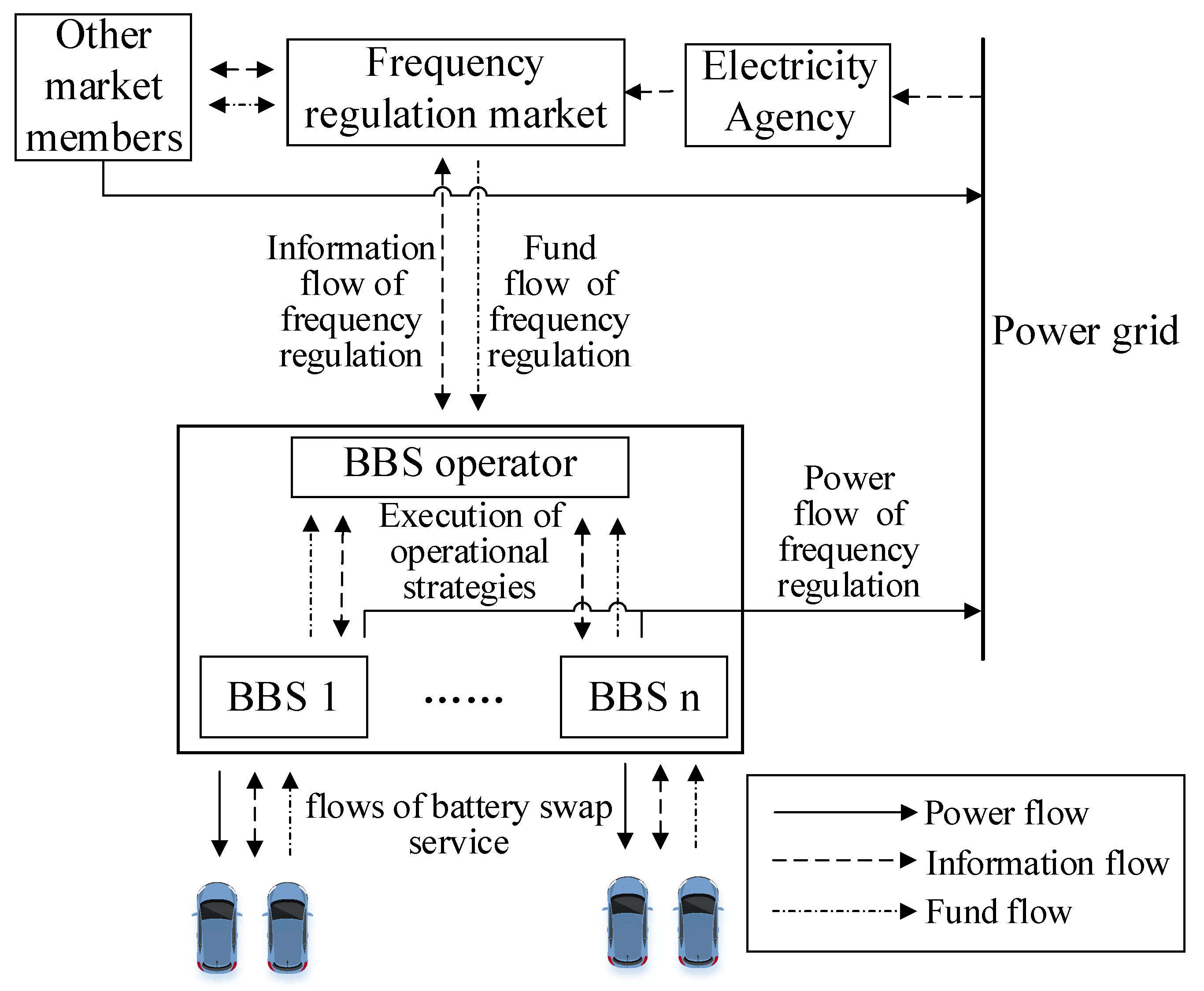
2. Model for Battery Swap Station Cluster Participating in Frequency Regulation Service
2.1. Model for Battery Swap Station Cluster Participating in Frequency Regulation Service
2.2. Model for Battery Swap Station Cluster Participating in Frequency Regulation Service
2.2.1. Operating Costs
2.2.2. Operating Income
2.2.3. Model for Battery Swap Station Cluster Participating in Frequency Regulation Service
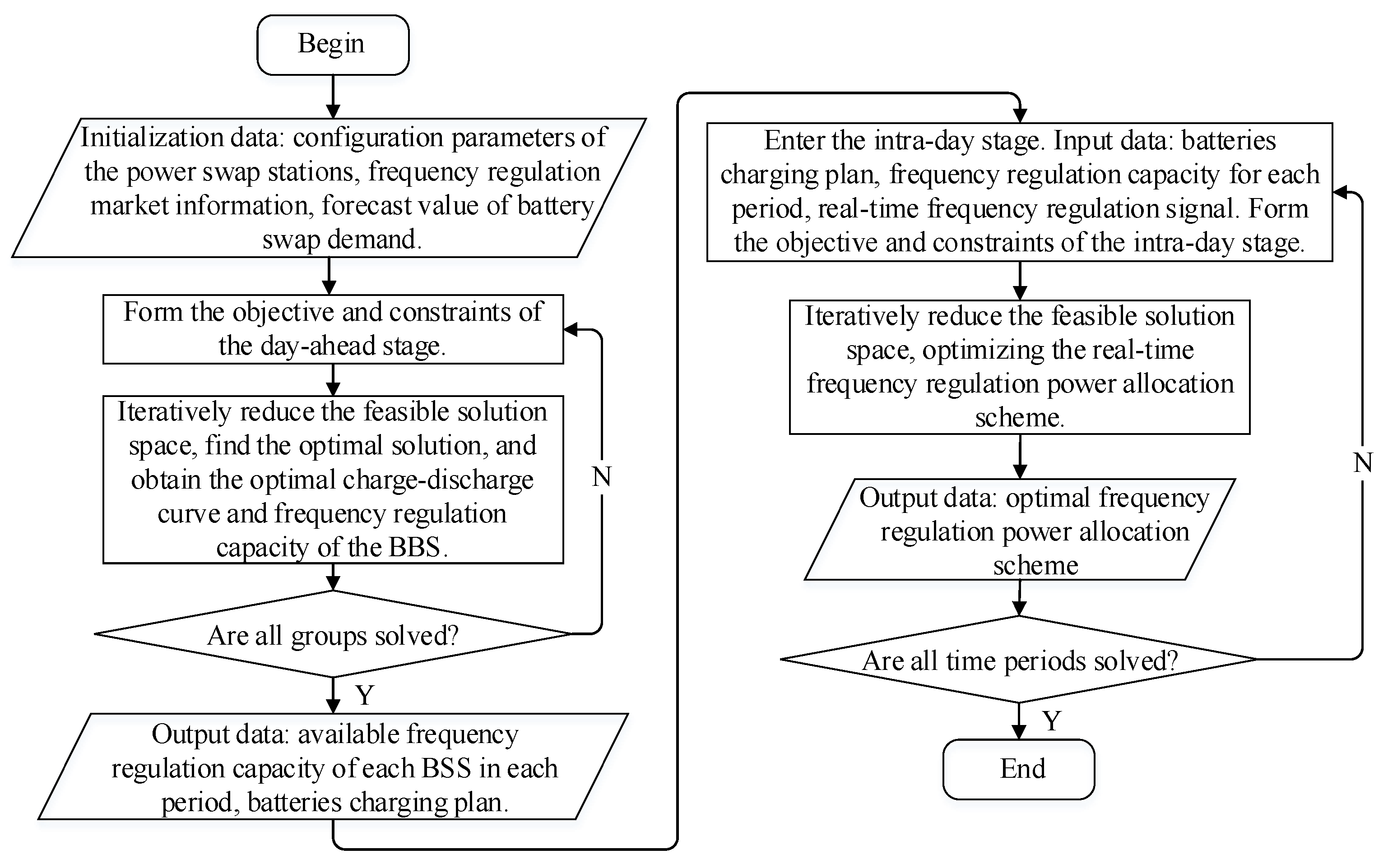
3. Two-Stage Strategy for Battery Swap Station Cluster Participating in Frequency Regulation Service
3.1. Day-Ahead Operation
- Determining the available FR capacity of each station on the next day;
- Arranging a battery charging plan. In order to achieve the above goal, it is necessary to optimize the solution based on the predicted value of battery swap demand and the FR demand issued by the power sector.
3.1.1. Objective Function
3.1.2. Constraints
- Battery energy constraints
- 2.
- FR service rules
- 3.
- Battery swap demand
3.2. Intra-Day Operation
3.2.1. Objective Function
3.2.2. Constraints
- (1)
- Loss of revenue
- (2)
- Power constraints of the grid and battery
3.3. Two-Stage Strategy for Battery Swap Station Cluster Participating in Frequency Regulation Service
- Divide the original problem into n MILP problems according to the number of BSSs;
- Perform linear relaxation on the MILP problem and determine the relaxed solution space and the corresponding upper and lower bounds of the objective function;
- The substitution problem, after linear relaxation, is divided into several sub-problems , whose solution set is and requires . For each sub-problem, if the optimal solution of the sub-problem is a feasible solution of the original problem, it is the optimal solution of the MILP problem and the calculation is completed; otherwise, the value of the objective function is regarded as the new upper bound of the MILP problem. The optimal solution of the sub-problem that is the feasible solution of the MILP problem is selected and its objective function is regarded as the lower bound of the MILP problem;
- Abandon the sub-problems where the objective function value of the optimal solution is less than and keep the sub-problems where the objective function value of the optimal solution is greater than ;
- Select the sub-problem with the largest objective function of the optimal solution and repeat 1 and 2. If the optimal feasible solution of the sub-problem is found, the maximum value of the objective function of the feasible solution and all the previously retained sub-problems is regarded as the new lower bound and d is repeated until the optimal solution is found;
- Judge whether to traverse all the BSSs; if yes, end, otherwise, select the next BSS and go back to 2.
4. Case Study
4.1. Basic Data
4.2. Results and Comparisons
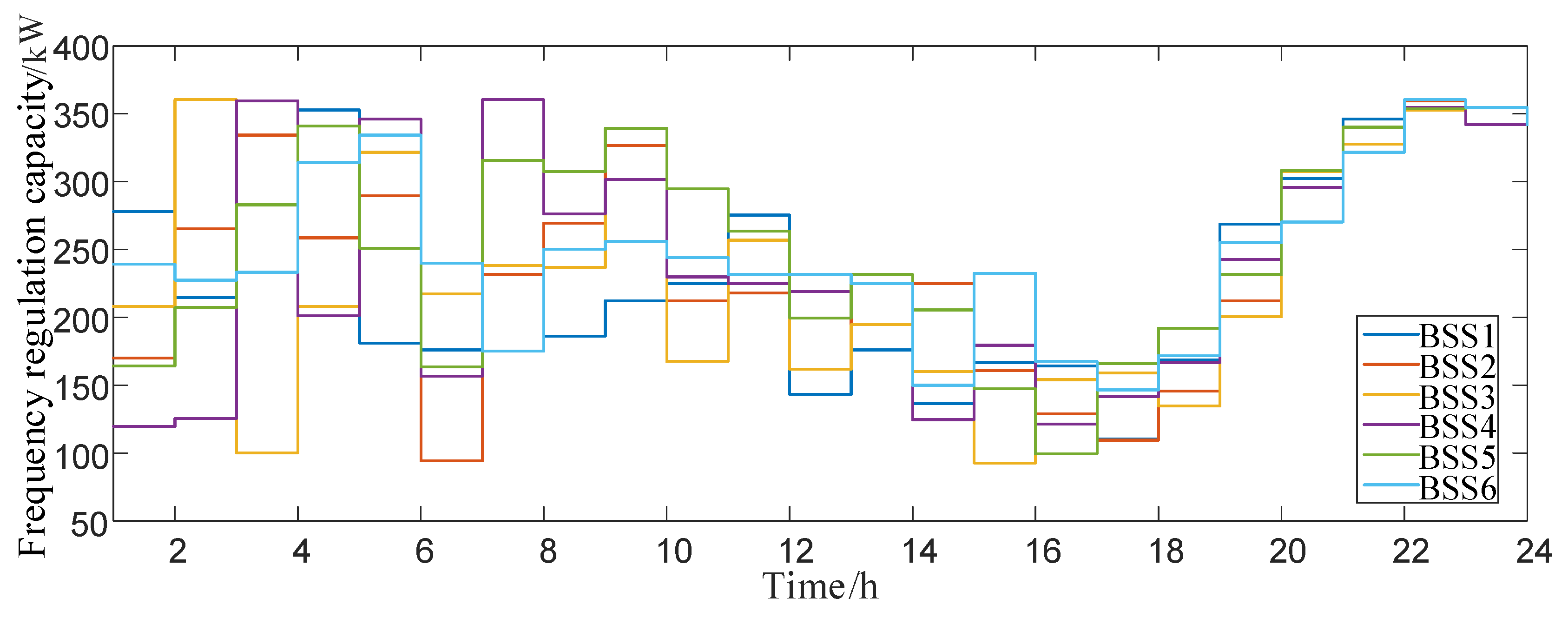
4.2.1. Results and Comparisons of Strategy in the Day-Ahead Stage
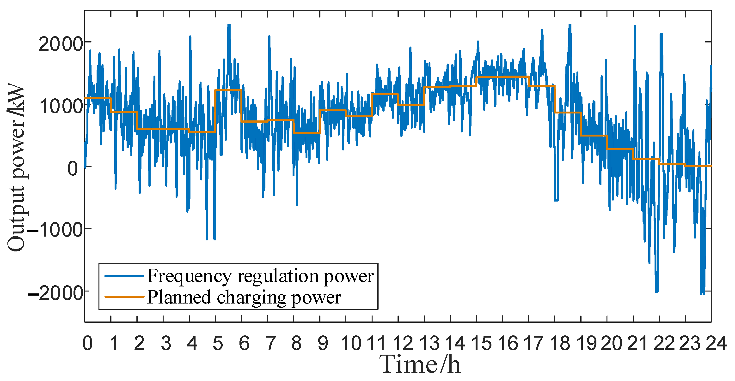
4.2.2. Results and Comparisons of Strategy in the Intra-Day Stage
5. Conclusions
- This work has a two-fold contribution. In theory, it provides a systematic and achievable method for a BSS cluster to participate in the FR service. In practice, it makes full use of idle batteries to participate in the FR service, which can improve the operating economy of BSSs. In addition, different from the conservativeness of other methods, such as robust optimization [39], the method in this paper is more conducive to improving the economy, while still maintaining a certain level of robustness through the power support and the planned use of limited resources.
- From the results of optimized operations, it can be seen that the battery swap income and FR income are complementary. When the battery exchange income is high/low, FR income is low/high. By using limited resources in a planned way, the FR service can bring great economic benefits to BSS operators, especially when the battery swap demand is low.
- FR power is allocated based on the busyness of the battery swap service, which realizes the power support between the BSSs. Numerical experiments using a realistic battery swapping project date and including comparison with the traditional method show that this method is more economical and synergistic, while still maintaining fast calculation speed, which is conducive to real-time regulation.
Author Contributions
Funding
Institutional Review Board Statement
Informed Consent Statement
Data Availability Statement
Conflicts of Interest
Appendix A

| Station Number | 1 | 2 | 3 | 4 | 5 | 6 |
|---|---|---|---|---|---|---|
| 0 | 0 | 0 | 0 | 0 | 0 | |
| 0 | 0 | 0 | 0 | 0 | 0 | |
| 0 | 0 | 0 | 0 | 0 | 0 | |
| 0 | 0 | 0 | 0 | 0 | 0 | |
| 0 | 0 | 0 | 0 | 0 | 0 | |
| 0 | 1 | 1 | 2 | 1 | 0 | |
| 3 | 1 | 2 | 1 | 1 | 3 | |
| 4 | 2 | 3 | 3 | 2 | 2 | |
| Battery swap demand/pc | 8 | 8 | 10 | 7 | 6 | 5 |
| 9 | 7 | 7 | 5 | 5 | 8 | |
| 6 | 6 | 8 | 6 | 4 | 4 | |
| 4 | 6 | 5 | 7 | 4 | 5 | |
| 4 | 5 | 6 | 4 | 5 | 4 | |
| 6 | 5 | 5 | 5 | 4 | 6 | |
| 5 | 5 | 4 | 6 | 5 | 4 | |
| 7 | 7 | 8 | 6 | 7 | 5 | |
| 12 | 10 | 9 | 8 | 9 | 9 | |
| 11 | 12 | 12 | 13 | 12 | 12 | |
| 10 | 11 | 10 | 12 | 11 | 13 | |
| 6 | 7 | 9 | 7 | 8 | 6 | |
| 4 | 4 | 4 | 4 | 4 | 4 | |
| 3 | 4 | 3 | 4 | 1 | 4 | |
| 1 | 2 | 2 | 1 | 2 | 1 | |
| 0 | 0 | 1 | 0 | 1 | 1 |
References
- Yang, J.; Yang, H.; Zhang, X. A Charging Optimization Strategy on Charging and Swapping Station for Electric Buses Based on Optimization of Switching Rules and Matching of Buses and Batteries. Proc. CSEE 2019, 39, 2337–2346. [Google Scholar]
- Liang, Y.; Cai, H.; Zou, G. Configuration and system operation for battery swapping stations in Beijing. Energy 2021, 214, 118883. [Google Scholar] [CrossRef]
- Wang, X.; Wang, J.; Liu, J. Vehicle to Grid FR Capacity Optimal Scheduling for Battery Swapping Station Using Deep Q-Network. IEEE Trans. Ind. Inform. 2021, 17, 1342–1351. [Google Scholar] [CrossRef]
- Worley, O.; Klabjan, D. Optimization of battery charging and purchasing at electric vehicle battery swap stations. In Proceedings of the 2011 IEEE Vehicle Power and Propulsion Conference (VPPC), Chicago, IL, USA, 6–9 September 2011; pp. 1–4. [Google Scholar]
- Deilami, S.; Masoum, A.S.; Moses, P.S. Real-time coordination of plug-in EV charging in smart girds to minimize power losses and improve voltage profile. IEEE Trans. Smart Grid 2011, 2, 456–467. [Google Scholar] [CrossRef]
- Takagi, M.; Iwafune, Y.; Yamamoto, Y.; Yamaji, K.; Okano, K.; Hiwatari, R.; Ikeya, T. Energy Storage of PV using batteries of battery-switch stations. In Proceedings of the 2010 IEEE International Symposium on Industrial Electronics, Bari, Italy, 4–7 July 2010. [Google Scholar]
- Liu, X.; Zhao, T.; Yao, S.; Soh, C.B.; Wang, P. Distributed Operation Management of Battery Swapping-Charging Systems. IEEE Trans. Smart Grid 2019, 10, 5320–5333. [Google Scholar] [CrossRef]
- Ban, M.; Zhang, Z.; Li, C.; Li, Z.; Liu, Y. Optimal scheduling for electric vehicle battery swapping-charging system based on nanogrids. Int. J. Electr. Power Energy Syst. 2021, 130, 106967. [Google Scholar] [CrossRef]
- Wang, L.; Chen, S.; Pedram, M. Optimal joint management of charging and battery swapping service for electric vehicles. In Proceedings of the 2017 9th Annual IEEE Green Technologies Conference (GreenTech), Denver, CO, USA, 29–31 March 2017; pp. 328–333. [Google Scholar]
- Chu, H.; Xie, D. Charging/discharging control strategy of EV charging-discharging-storage integrated station considering operational status of power grid. Electr. Power Autom. Equip. 2018, 38, 96–101. [Google Scholar]
- Yuan, H.; Wei, G.; Zhu, L. Optimal scheduling for micro-grid considering EV charging-swapping-storage integrated station. IET Gener. Transm. Distrib. 2018, 14, 1127–1137. [Google Scholar] [CrossRef]
- Habibifar, R.; Aris Lekvan, A.; Ehsan, M. A risk-constrained decision support tool for EV aggregators participating in energy and frequency regulation markets. Electr. Power Syst. Res. 2020, 185, 106367. [Google Scholar] [CrossRef]
- Han, S.; Han, S.; Sezaki, K. Estimation of Achievable Power Capacity from Plug-in Electric Vehicles for V2G Frequency Regulation: Case Studies for Market Participation. IEEE Trans. Smart Grid 2011, 2, 632–641. [Google Scholar] [CrossRef]
- Han, S.; Han, S.; Sezaki, K. Development of an optimal vehicle-to-grid aggregator for Frequency Regulation. IEEE Trans. Smart Grid 2010, 1, 65–72. [Google Scholar]
- Liu, H.; Qi, J.; Wang, J.; Li, P.; Li, C.; Wei, H. EV Dispatch Control for Supplementary Frequency Regulation Considering the Expectation of EV Owners. IEEE Trans. Smart Grid 2018, 9, 3763–3772. [Google Scholar] [CrossRef] [Green Version]
- Lv, L.; Gao, C.; Li, H.; Shen, T.; Wei, X.; Liu, L. Estimation of plug-in electric vehicles schedulable capacity. In Proceedings of the 2016 3rd International Conference on Systems and Informatics (ICSAI), Shanghai, China, 19–21 November 2016; pp. 223–229. [Google Scholar]
- Wu, C.; Lin, X.; Sui, Q. Two-stage self-scheduling of battery swapping station in day-ahead energy and Frequency Regulation markets. Appl. Energy 2020, 283, 116285. [Google Scholar] [CrossRef]
- Yao, E.; Wong, V.W.S.; Schober, R. Robust Frequency Regulation Capacity Scheduling Algorithm for Electric Vehicles. IEEE Trans. Smart Grid 2017, 8, 984–997. [Google Scholar] [CrossRef]
- Sun, S.; Dong, M.; Liang, B. Real-time welfare-maximizing regulation allocation in dynamic aggregator-EVs system. IEEE Trans. Smart Grid 2014, 5, 1397–1409. [Google Scholar] [CrossRef] [Green Version]
- Scarabaggio, P.; Carli, R.; Cavone, G.; Dotoli, M. Smart Control Strategies for Primary Frequency Regulation through Electric Vehicles: A Battery Degradation Perspective. Energies 2020, 13, 4586. [Google Scholar] [CrossRef]
- Yan, G.; Liu, D.; Li, J.; Mu, G. A cost accounting method of the Li-ion battery energy storage system for frequency regulation considering the effect of life degradation. Prot. Control Mod. Power Syst. 2018, 3, 4. [Google Scholar] [CrossRef]
- Gao, H.; Wu, X. A Survey on Battery-Swapping Mode of Electric Vehicles. Power Syst. Technol. 2013, 37, 891–897. [Google Scholar]
- Zhao, Z.; Yang, P.; Wang, Y.; Xu, Z.; Guerrero, J.M. Dynamic Characteristics Analysis and Stabilization of PV-Based Multiple Microgrid Clusters. IEEE Trans. Smart Grid 2019, 10, 805–818. [Google Scholar] [CrossRef] [Green Version]
- Wang, M.; He, Y.; Yang, T.; Jia, Y.; Xu, Z. Cascaded Voltage Control for Electric Springs with DC-Link Film Capacitors. IEEE J. Emerg. Sel. Top. Power Electron. 2020, 8, 3982–3994. [Google Scholar] [CrossRef]
- Schneider, F.; Thonemann, U.W.; Klabjan, D. Optimization of Battery Charging and Purchasing at Electric Vehicle Battery Swap Stations. Transp. Sci. 2017, 52, 1211–1234. [Google Scholar] [CrossRef]
- Zhe, L.; Ouyang, M. The pricing of charging for electric vehicles in China—Dilemma and solution. Energy 2011, 36, 5765–5778. [Google Scholar]
- Carli, R.; Dotoli, M. A Distributed Control Algorithm for Optimal Charging of Electric Vehicle Fleets with Congestion Management. IFAC-Pap. 2018, 51, 373–377. [Google Scholar] [CrossRef]
- Wu, X.; Feng, Q.; Bai, C.; Lai, C.S.; Jia, Y.; Lai, L.L. A novel fast-charging stations locational planning model for electric bus transit system. Energy 2021, 224, 120106. [Google Scholar] [CrossRef]
- Lai, C.S.; Jia, Y.; Dong, Z.; Wang, D.; Tao, Y.; Lai, Q.H.; Wong, R.T.; Zobaa, A.F.; Wu, R.; Lai, L.L. A review of technical standards for smart cities. Clean Technol. 2020, 2, 290–310. [Google Scholar] [CrossRef]
- Zhao, Z.; Guo, J.; Lai, C.S.; Xiao, H.; Zhou, K.; Lai, L.L. Distributed Model Predictive Control Strategy for Islands Multimicrogrids Based on Noncooperative Game. IEEE Trans. Ind. Inform. 2021, 17, 3803–3814. [Google Scholar] [CrossRef]
- Symeonidou, M.M.; Zioga, C.; Papadopoulos, A.M. Life cycle cost optimization analysis of battery storage system for residential photovoltaic panels. J. Clean. Prod. 2021, 309, 127234. [Google Scholar] [CrossRef]
- Wang, Z.; Zhong, J.; Li, J. Design of performance-based frequency regulation market and its implementations in real-time operation. Int. J. Electr. Power Energy Syst. 2017, 87, 187–197. [Google Scholar] [CrossRef]
- Nassourou, M.; Blesa, J.; Puig, V. Robust Economic Model Predictive Control Based on a Zonotope and Local Feedback Controller for Energy Dispatch in Smart-Grids Considering Demand Uncertainty. Energies 2020, 13, 696. [Google Scholar] [CrossRef] [Green Version]
- Sortomme, E.; El-Sharkawi, M.A. Optimal power flow for a system of microgrids with controllable loads and battery storage. In Proceedings of the 2009 IEEE/PES Power Systems Conference and Exposition, Seattle, WA, USA, 15–18 March 2009; pp. 1–5. [Google Scholar]
- Wang, H.; Zhang, Y.; Mao, H. Load forecasting method of EVs based on time charging probability. In Proceedings of the 2018 International Conference on Power System Technolohy, Guangzhou, China, 6–8 November 2018; p. 1731. [Google Scholar]
- Wang, M.; He, Y.; Jia, Y.; Xu, Z. A Power-Decoupled Current Source Inverter for PV Energy Harvest and Grid Voltage Regulation. IEEE Trans. Ind. Electron. 2020, 68, 9540–9549. [Google Scholar] [CrossRef]
- Tomasz, P.P.; O’Neill, M. Grammatical evolution for constraint synthesis for mixed-integer linear programming. Swarm Evol. Comput. 2021, 64, 100896. [Google Scholar]
- Pjm-Data Miner 2. Available online: https://dataminer2.pjm.com/feed/reg_market_results/definition (accessed on 13 January 2016).
- Hosseini, S.M.; Carli, R.; Dotoli, M. A residential demand-side management strategy under nonlinear pricing based on robust model predictive control. In Proceedings of the 2019 IEEE International Conference on Systems, Man and Cybernetics (SMC), Bari, Italy, 6–9 October 2019; pp. 3243–3248. [Google Scholar]


| Stage | Number of Real Variables | Number of Integer Variables | Number of Bounding Constraints | Number of Inequality Constraints | Number of Equality Constraints |
|---|---|---|---|---|---|
| day-ahead | 2i 1t 2 | 4it | 4it | (8i + 5)t | it + j3 |
| intra-day | 2i + 1 | 0 | 4i + 2 | 6i + j + d 4 | i + 4 |
| Parameter | Set Value |
|---|---|
| Number of stations/pc | 6 |
| Number of batteries/pc | 40 |
| Number of chargers/pc | 30 |
| Electricity price for battery swap service/(USD/kWh) | 0.1566 |
| Basic fee for battery swap service/USD | 1.566 |
| Operating commercial electricity price/USD | 0.1181 |
| Battery capacity/kWh | 40 |
| Single battery power upper limit/kW | 12 |
| Charger efficiency/% | 95 |
| SOC lower limit/% | 20 |
| Station | Operating Costs/USD | Battery Swap Income/USD | FR Income/USD | Net Income/USD |
|---|---|---|---|---|
| BSS 1 | 429.01 | 780.46 | 268.38 | 619.82 |
| BSS 2 | 429.39 | 780.83 | 268.95 | 620.39 |
| BSS 3 | 452.61 | 826.12 | 261.10 | 634.61 |
| BSS 4 | 418.27 | 765.49 | 271.39 | 618.60 |
| BSS 5 | 386.29 | 697.28 | 286.66 | 597.64 |
| BSS 6 | 401.91 | 727.59 | 280.65 | 606.33 |
| Sum | 2517.53 | 4577.83 | 1637.18 | 3697.46 |
| Station | Prediction of the Number of Battery Swap Demand/pc | When the Battery Swap Demand Arises |
|---|---|---|
| BSS 1 | 4 |  |
| BSS 2 | 2 |  |
| BSS 3 | 3 |  |
| BSS 4 | 3 |  |
| BSS 5 | 2 |  |
| BSS 6 | 2 |  |
Publisher’s Note: MDPI stays neutral with regard to jurisdictional claims in published maps and institutional affiliations. |
© 2021 by the authors. Licensee MDPI, Basel, Switzerland. This article is an open access article distributed under the terms and conditions of the Creative Commons Attribution (CC BY) license (https://creativecommons.org/licenses/by/4.0/).
Share and Cite
Zhang, F.; Yao, S.; Zeng, X.; Yang, P.; Zhao, Z.; Lai, C.S.; Lai, L.L. Operation Strategy for Electric Vehicle Battery Swap Station Cluster Participating in Frequency Regulation Service. Processes 2021, 9, 1513. https://doi.org/10.3390/pr9091513
Zhang F, Yao S, Zeng X, Yang P, Zhao Z, Lai CS, Lai LL. Operation Strategy for Electric Vehicle Battery Swap Station Cluster Participating in Frequency Regulation Service. Processes. 2021; 9(9):1513. https://doi.org/10.3390/pr9091513
Chicago/Turabian StyleZhang, Fan, Senjing Yao, Xiankai Zeng, Ping Yang, Zhuoli Zhao, Chun Sing Lai, and Loi Lei Lai. 2021. "Operation Strategy for Electric Vehicle Battery Swap Station Cluster Participating in Frequency Regulation Service" Processes 9, no. 9: 1513. https://doi.org/10.3390/pr9091513
APA StyleZhang, F., Yao, S., Zeng, X., Yang, P., Zhao, Z., Lai, C. S., & Lai, L. L. (2021). Operation Strategy for Electric Vehicle Battery Swap Station Cluster Participating in Frequency Regulation Service. Processes, 9(9), 1513. https://doi.org/10.3390/pr9091513