Article

CFD Study of the Numbering up of Membrane Microreactors for CO2 Capture

1
Department of Chemical Engineering, Cyprus University of Technology, 57 Corner of Athinon and Anexartisias, Limassol 3036, Cyprus
2
Division of Chemical & Energy Engineering, School of Engineering, London South Bank University, London SE1 0AA, UK
3
Department of Chemical Engineering, University College London, London WCIE 7JE, UK
*
Author to whom correspondence should be addressed.
Processes 2021, 9(9), 1515; https://doi.org/10.3390/pr9091515
Submission received: 29 June 2021 / Revised: 24 August 2021 / Accepted: 24 August 2021 / Published: 26 August 2021
(This article belongs to the Special Issue Gas Emissions Control and Utilization)

Abstract

:
Carbon dioxide (CO2) is one of the major atmospheric greenhouse gases (GHG). The continuous increase of CO2 concentration and its long atmospheric lifetime may cause long-term negative effects on the climate. It is important to develop technologies to capture and minimize those emissions into the atmosphere. The objective of this work is to design and study theoretically and experimentally a numbering-up/scale-out membrane microreactor in order to be used as a capture system. The main aim of the work is to obtain an even flow distribution at each plate of the reactor. Nearly uniform flow distribution was achieved at each layer of the numbering-up microreactor according to the carried-out CFD models. The maximum difference between the average velocities was less than 6% for both gas and liquid flows. To obtain better flow distribution into the microreactor, the radius of the inlet/outlet tube was optimized. Results from CFD and experimental simulations do not match, and slightly maldistribution in achieved in the experimental system due to phase breakthrough and imperfections on the fabrication of the plates. Moreover, comparing the single channel microreactor to the scale-out microreactor, the latter showed poorer performance on CO2 removal while expecting the reactors to have similar performance. By installing inserts with different channel widths, the experimental results were identical to the original case.

1. Introduction

The rapid development of industries, in recent years, has led to increase greenhouse gas (GHG) emissions in the atmosphere [1]. Carbon dioxide (CO2) is the most important GHG due to the dependence of fossil fuels as energy source. The concentration of CO2 has increased over the past years. Continuous increase of CO2 concentration may cause long-term impacts on the climate. Moreover, it is expected that the global annual mean temperature continue increasing for at least the next two centuries by 3–5 °C per century [2]. The impact of CO2 in global warming is one of the most important contemporary environmental issues. Therefore, it is important to have the appropriate technologies to minimize the discharge of CO2 into the atmosphere [3].
Carbon capture and storage (CCS) is the most indicated technology to stabilize the concentration of CO2 in the atmosphere. CCS involves the capture of CO2 at the point of generation, compressing it to a supercritical fluid and then sequestering it. CCS is more often used at non-biological processes where combustion takes place and produces CO2 [4]. So far, several carbon capture technologies have been developed and tested on laboratory and pilot scale. Those separation techniques include physical and chemical absorption, adsorption, membrane separation [5] and cryogenic distillation. Capture systems’ aim is the separation of CO2 from a gas mixture which consists only the combustion products. The capture can be achieved with three different technological concepts: post combustion technology, pre combustion technology and oxyfuel capture systems [4].
CO2 capture can be achieved through many techniques including membrane gas absorption. The concept of the use of microchannel gas-liquid contactor improves the vapor-liquid mass transfer [6]. Membrane contactors bring two phases into contact, for the purpose of mass transfer between them, without dispersion of one phase into the other. The membrane acts as a fixed interface while the transport of volatiles takes place through the membrane. The advantages of these contactors include relatively large interfacial area between the two phases, no fluid-fluid dispersion while floating, foaming and emulsion formation can be avoided and scale-up can be facilitated [7]. They can also have low weight and low capital investment which make them an attractive research area [8].
Membrane contactors also have some disadvantages, where they can be minimized by using an ideal membrane with high porosity and well defined pore size together with short mass transfer paths [7]. Hafeez et al. [9], reviewed the usage of membrane contactors as a capture system and showed that not only membrane contactors are widely used but also amine solvents for CO2 removal. Constantinou et al. [10,11,12,13], studied the CO2 absorption in a silicon nitrite mesh contactor, in a flat membrane micro-structured contactor and in a metal mesh micro-structured reactor using diethanolamine (DEA), monoethanolamine (MEA) and sodium hydroxide (NaOH) solutions. Furthermore, three membrane/mesh contactors (PTFE membrane contactor, nickel mesh contactor and an eight-channel PTFE membrane contactor) were examined for capturing CO2 using NaOH as absorbent.
Rostami et al. [14] investigated experimentally the absorption of CO2 in a polypropylene hollow fiber membrane contactors (HFMC) using a mixture of ionic liquid ([Bmim][BF4]) and methyl-diethanolamine [MDEA] as absorbents increasing the physical solubility of CO2 in the solvent. The absorption of CO2 in membrane contactors using ionic liquid solutions in physical and chemical absorbents was examined using CFD models [15]. Magnone et al. [16] investigated the absorption efficiency of CO2 using five single amine-based absorbents and sixteen correlations between single and blended amine-based absorbents in a hydrophobic modified ceramic HFMCs. Sohaib et al. [17], developed a mathematical model for a non-isothermal absorption process of CO2 in HFMC using four amino acid-basic ionic liquids as absorbents.
Microchannel reactors are a very promising development for carbon capture. The reactors under investigation have an array of parallel microchannels for reaction’s requirements that could not be achieved with a single microchannel. Griffini and Gavriilidis [18], analyzed the effects of a microplate design on a fluid flow uniformity. Mohammati et al. [19] used a CFD model to show how the flow uniformity is affected by the dimensions of the microchannels. Tonomura et al. [20] showed that the flow uniformity within the microchannels depends on the shape of the manifold, length, location of fins and inlet flow rate. A plate-fin microreactor was examined by Huang et al. [21] in order to optimize the shape of the manifold in order to achieve the best uniformity in the system. Castedo et al. [22] examined the flow distribution of a silicon microreactor containing microchannels using CFD simulations. The design of the microreactor has an important role on flow distribution. To achieve uniform flow distribution based on literature, the channels must have high length, small width and the manifold design has to be symmetric.
The production of a product may not meet the requirements of an industry. A microreactor must be demonstrated to increase the production volume of a process and be used on industrial scale. This can be achieved by using scale-out or numbering-up approach. This approach is therefore cost-effective, time-efficient, with a small-footprint and better control of reactions enabling changes in production volume by simply increasing or decreasing the number of reactors employed [23,24]. Scaling-up is a cost- and time-consuming process, which is not feasible for microreactors considering heat and mass transfer problems, so an alternative solution was developed. It is the most optimal way of enhancing the production capacity while retaining the advantages of small channels.
Numbering-up can be performed in two ways. External numbering-up is referred to as the increase of the number of microreactors by stacking up several microreactors [25] and internal numbering-up means the parallel connection of the functional elements only, rather than of the complete devices [23]. Togashi et al. [24] developed a micro-structured system using 20 numbering-up microreactors showing that the system was able to increase the production scale without decreasing the yield. Kikutani et al. [25] constructed and operated a numbering-up system where a single-layered and a ten-layered pile-up microreactors were compared. They found that the throughput of the ten-layered microreactor was almost ten times more that the throughput of the single-layered microreactor. Castedo et al. [22] examined the flow distribution in a single and a triple stack microreactor by developing CFD models. The simulations revealed the homogeneous distribution of the gas stream among the channels. CFD simulations were carried out to characterize the fluid distribution within a flat constructed distributor with dichotomic tree structures by Su et al. [26] and a numbering-up strategy for the scale-up of gas-liquid photocatalytic reactions [23]. The flow distribution was examined for a 2-, 4- and an 8-capillary system and showed a very good performance of the uniformity in the reactors. Another numbering-up study was examined for a luminescent solar concentrator-based photo microreactor by Zhao et al. [27]. This study investigated the flow distribution in 8, 16 and 32 parallel microchannels using bifurcated flow distributor. Tonomura et al. [28] developed a split-and-recombined-type flow distributor (SRFD) and five parallelized monolithic microreactors.
The objective of this work is to design and study theoretically and experimentally micro-structured reactors in parallel. Based on the approach of the numbering-up microreactors this work examines the flow uniformity of each plate of the microreactor. The aim of the numbering-up study is to design a microreactor capable to be used at industrial scale with high throughput comparing to the single microchannel reactor. Pressure profiles are discussed and the effect of the radius of inlet and outlet tube on flow uniformity is examined theoretically and experimentally.

2. Materials and Methods

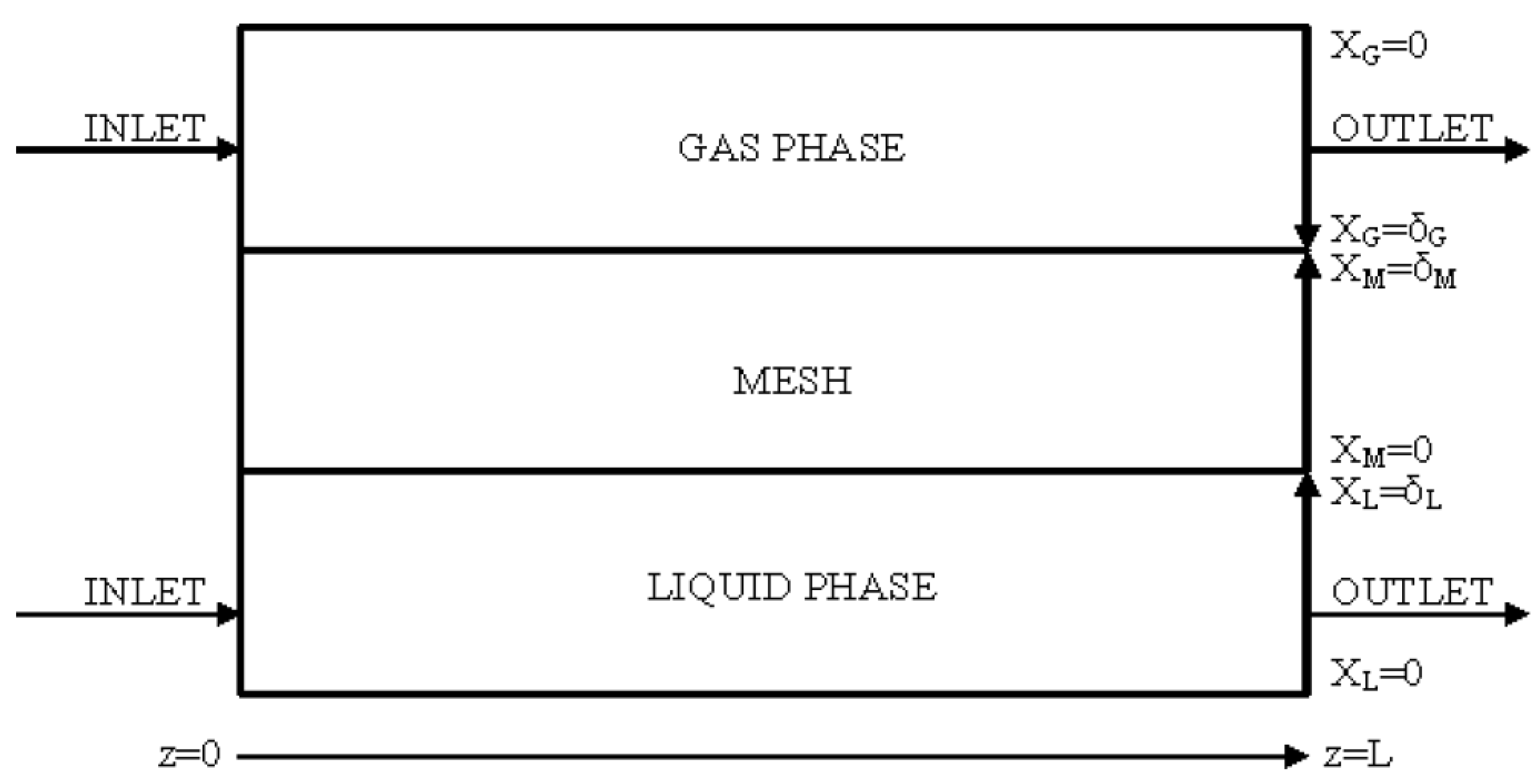
2.1. CFD Methodology

In this work the numbering-up or scale-out approach of a microreactor refers to four microplates which were placed in a parallel configuration. A microreactor was designed to examine the velocity profile within each microplate for both gas and liquid flows. The dimensions of the microreactor are 850 μm chamber thickness for the gas stream and 200 μm for the liquid stream, 90 mm chamber length and the inlet and outlet widths are 20 mm, respectively. To ensure equal flow distribution, CFD simulations carried out. The fluid flow in microchannels is considered to be laminar and also, the fluid behavior is time-independent during the optimizations in the manifold design problems. Reaction phenomena are not considered. The gas stream consists of 20% CO2/N2. Figure 1 represents a schematic of the CFD modelling domains.
For laminar flow in the microchannels to be valid, Reynolds number should be lower than 2000, the Reynolds number can be defined as:
Re = ρ i   u i   D H μ i
where ui is the characteristic velocity of the gas or liquid stream, and DH the hydraulic diameter.
The inlet velocity for the gas flow, that has been used, was 0.648 m/s and for the liquid flow the inlet velocity was 0.02 m/s. In both cases, the Reynolds number was found below the critical value in every channel (a maximum value of Re = 76.32 was found for the inlet gas flow and a maximum value of Re = 19.54 was found for the inlet liquid flow) allowing the flow to be regarded to as laminar.
CFD simulations were carried out to ensure that the fluid is equally distributed in each layer of the microreactor. For the CFD simulations the Navier stokes equations:
u   u = p + μ i 2 u
combined with the equation of continuity,
u = 0
where u is the fluid vector, and p the pressure, are solved using COMSOL 5.5. A three-dimensional model (see Figure 2) was employed with no-slip boundary conditions at all walls and a fixed pressure at the outlet (p = 0 N m−2). By increasing the number of degrees of freedom, no significant variation in the results was detected meaning that the mesh grid has no influence on the calculates distribution. By increasing the number of degrees of freedom, the number of the elements is also increased, and the solution is obtained with high accuracy. Using boundary layers, the mesh has higher resolution in the channels area (porous area). Table 1 displays the parameters used for the CFD modelling study. The boundary conditions are as follows:
At   z = 0 ;    C CO 2 , l = 0 ,   C NAON , l   =   C NAON , 0
At   z = L ;    ϑ C CO 2 ϑ z = 0 ,   ϑ C NaOH ϑ z = 0 .
At   x L   = δ L ;    C CO 2 , l   =   C CO 2 , M ,   D CO 2 , l   ϑ C CO 2 , l ϑ x l = D CO 2 , M   ϑ C CO 2 , M ϑ x M
At   x L = 0 ;    ϑ C NaOH ϑ x l = 0 ,   ϑ C CO 2 ϑ x l = 0
At   x M = δ M ;    C CO 2 , M = mC CO 2 , g ,   D CO 2 , M   ϑ C CO 2 , M ϑ x M =   D CO 2 , g   ϑ C CO 2 , g ϑ x g ,   ϑ C NaOH ϑ x M = 0
At   x G = δ G ;    mC CO 2 , g = C CO 2 , M ,   D CO 2 , g   ϑ C CO 2 , g ϑ x g =   D CO 2 , M   ϑ C CO 2 , M ϑ x M
At   z = L ;    ϑ C CO 2 , M ϑ z = 0
At   z = 0 ;    C CO 2 , g = C CO 2 , 0

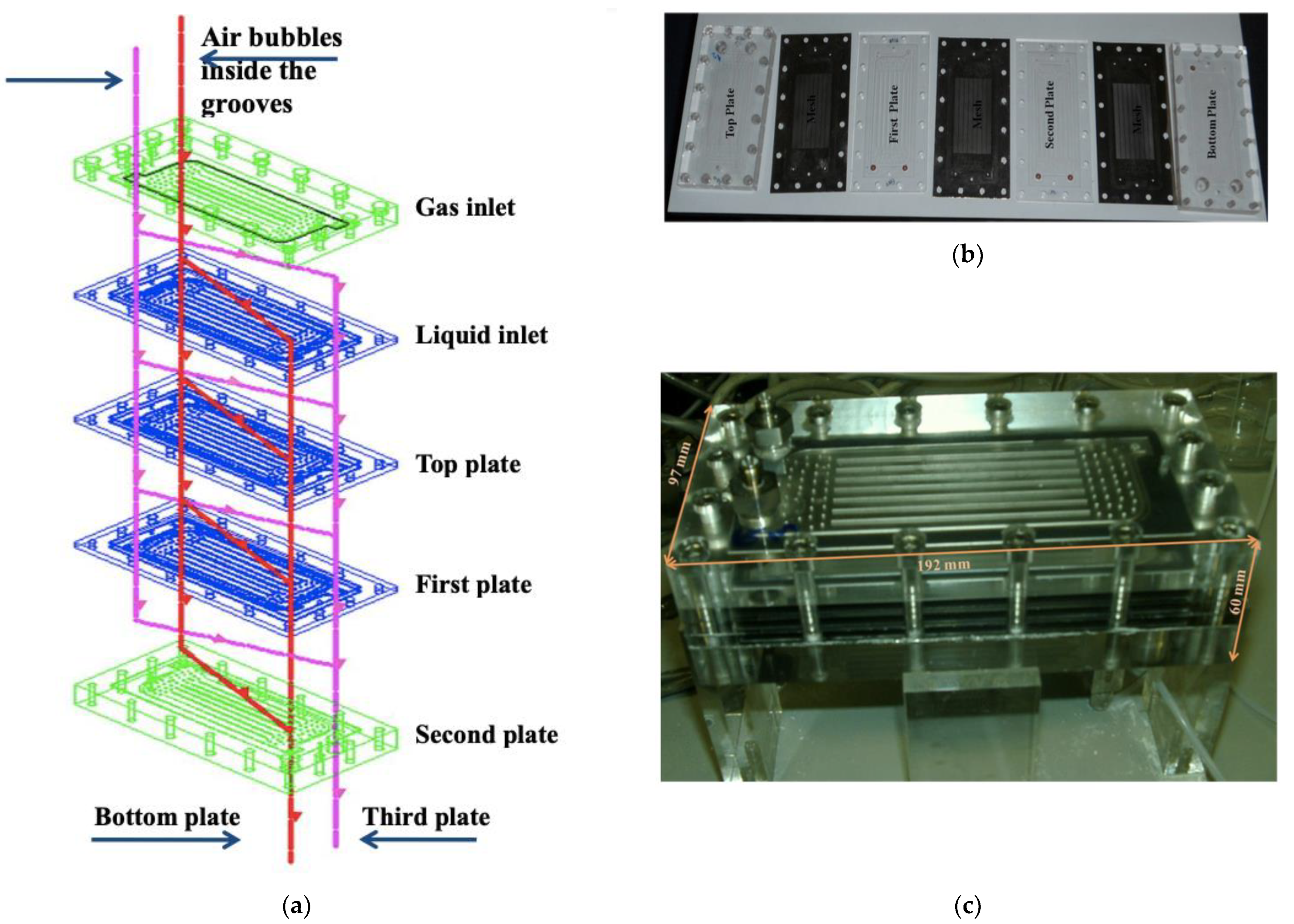
2.2. Experimental Methodology

A numbering-up metallic mesh microreactor was investigated for the absorption of CO2 in NaOH solution. The reaction system considered refers to the absorption of CO2 from 20 vol% CO2/N2 mixture within a solution of 2 M NaOH. The absorption of CO2 in the aqueous solution of sodium hydroxide is occurred in three steps [32]:
C O 2 ( g )     C O 2 ( l )
C O 2 ( l ) + O H     H C O 3
H C O 3 + O H     C O 3 2 + H 2 .
The overall reaction can be written as:
2 NaOH + C O 2     N a 2 C O 3 + H 2 O
In this ‘scale-out’ micromesh reactor, four meshes were integrated. (see Figure 3). The experimental set-up for a single plate, which was studied in previously published work [12], was used in order to examine the flow distribution and the performance of a numbering-up microreactor. The flow configuration for the scale-out metallic mesh reactor and a picture of the components of the microreactor with the meshes are shown in Figure 3. Three acrylic plates were machined together and placed in parallel between the top and the bottom plates of the metallic mesh reactor in order to have the configuration of Figure 3 and use four meshes. The liquid 2M NaOH enters the system in the bottom chamber of each microreactor, while the gas 20 vol% CO2/N2 flows above the mesh of each microplate. The outlet of the gas phase, before it gets into the gas chromatograph (GC), is passing through a liquid trap in order to collect any liquid in a case of breakthrough. The device used in this work comprises of 4 microreactors in which micro-structured mesh placed between two 18 mm thick acrylic plates. Gas flow rate varied from 920–1416 mL/min and liquid flowrate varied from 6.64–10.24 mL/min, which is four times larger the flowrate of the single metallic mesh reactor. The pressure difference between gas and liquid phase was kept at PG–PL ≈ 15–20 cm H2O.
To improve the flow distribution of each plate, experiments were performed by installing inserts with different channel widths (0.2, 0.5, 0.75 and 1 mm) in every inlet of each plate of the numbering-up reactor, for both flows (see Figure 4). The shape of the inserts was selected in this star shape to avoid the blocking of the inlets/outlets of the microreactor by the metallic mesh. Before the installation of the inserts blocking of the inlets/outlets of the microreactor was observed by the mesh as a result an excessive pressure drop was created withing the channels. The experimental ring is the same used for the single mesh reactor [12], with the difference that the flow rate is four times the flow rate used for the single mesh reactor. The main aim of that experiment was to better control the pressure drop over each plate and to keep it the same at each plate of the numbering-up reactor.

3. Results and Discussion

3.1. CFD Results

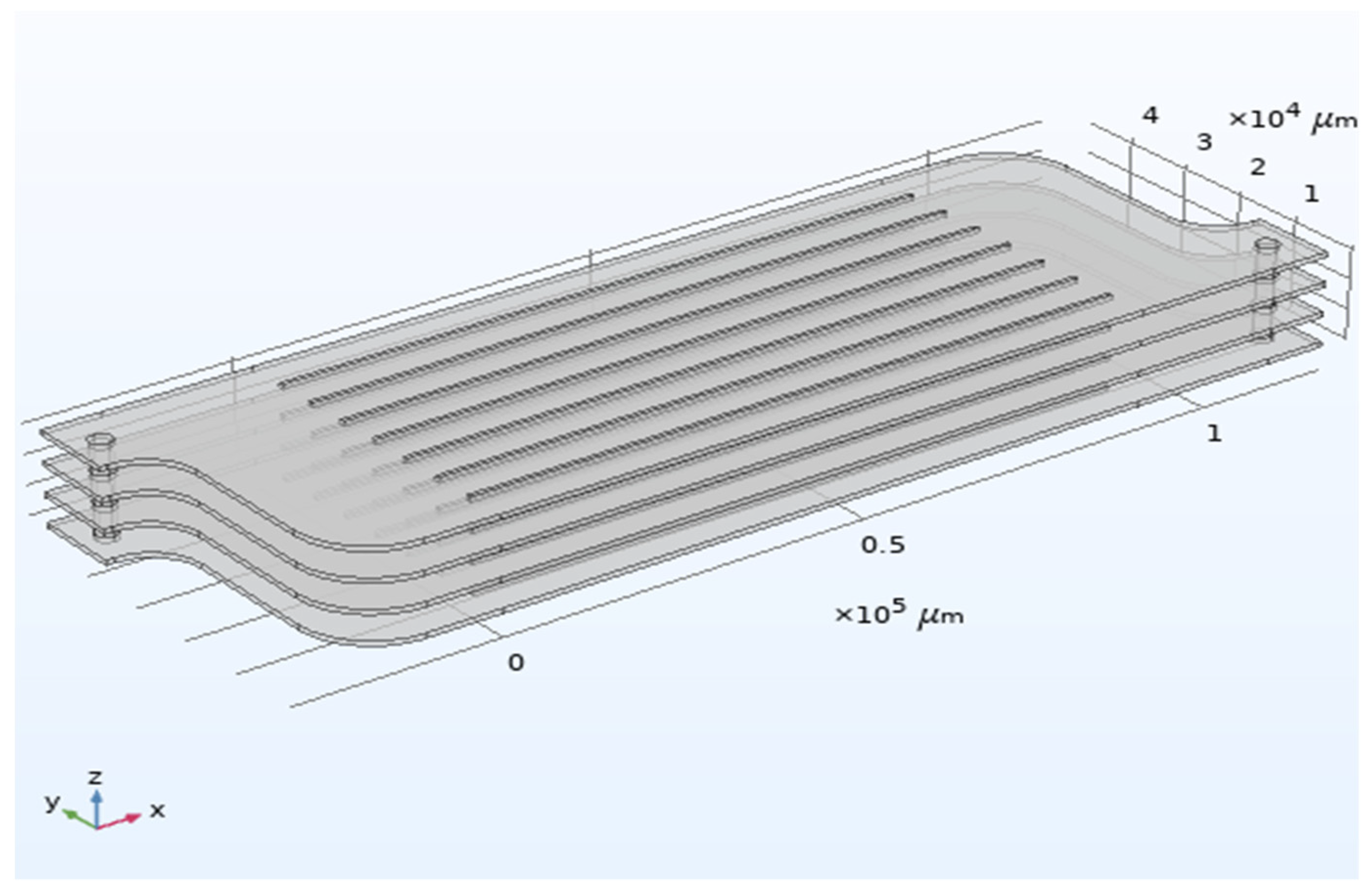
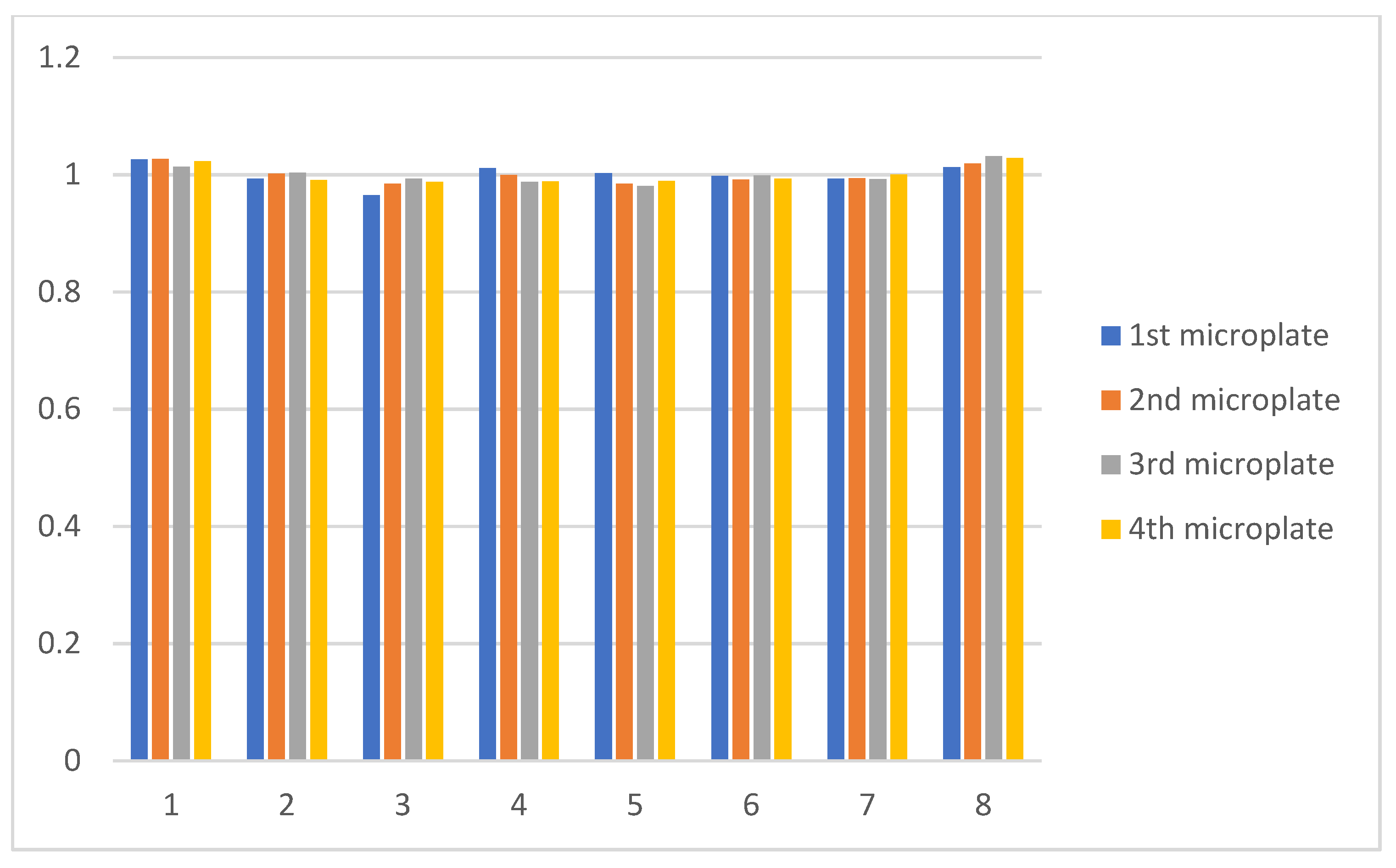
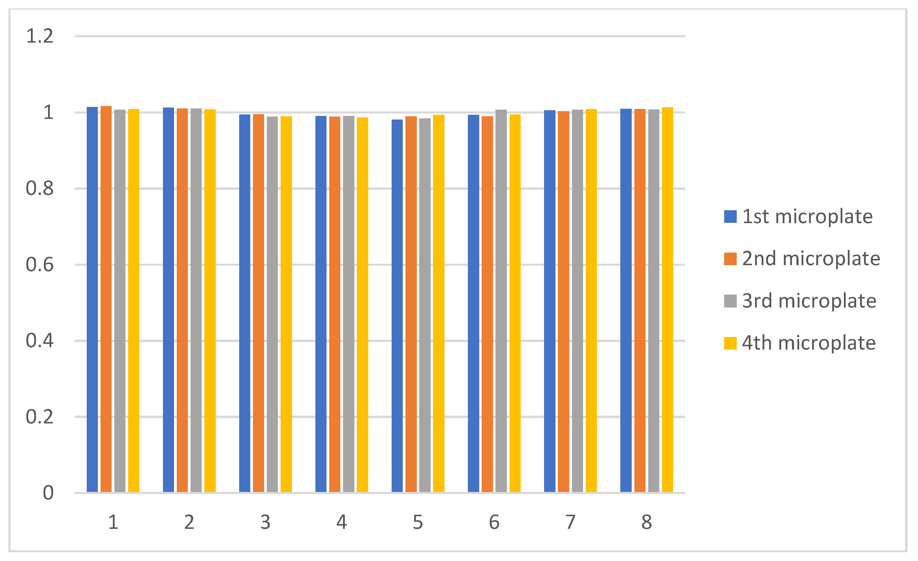
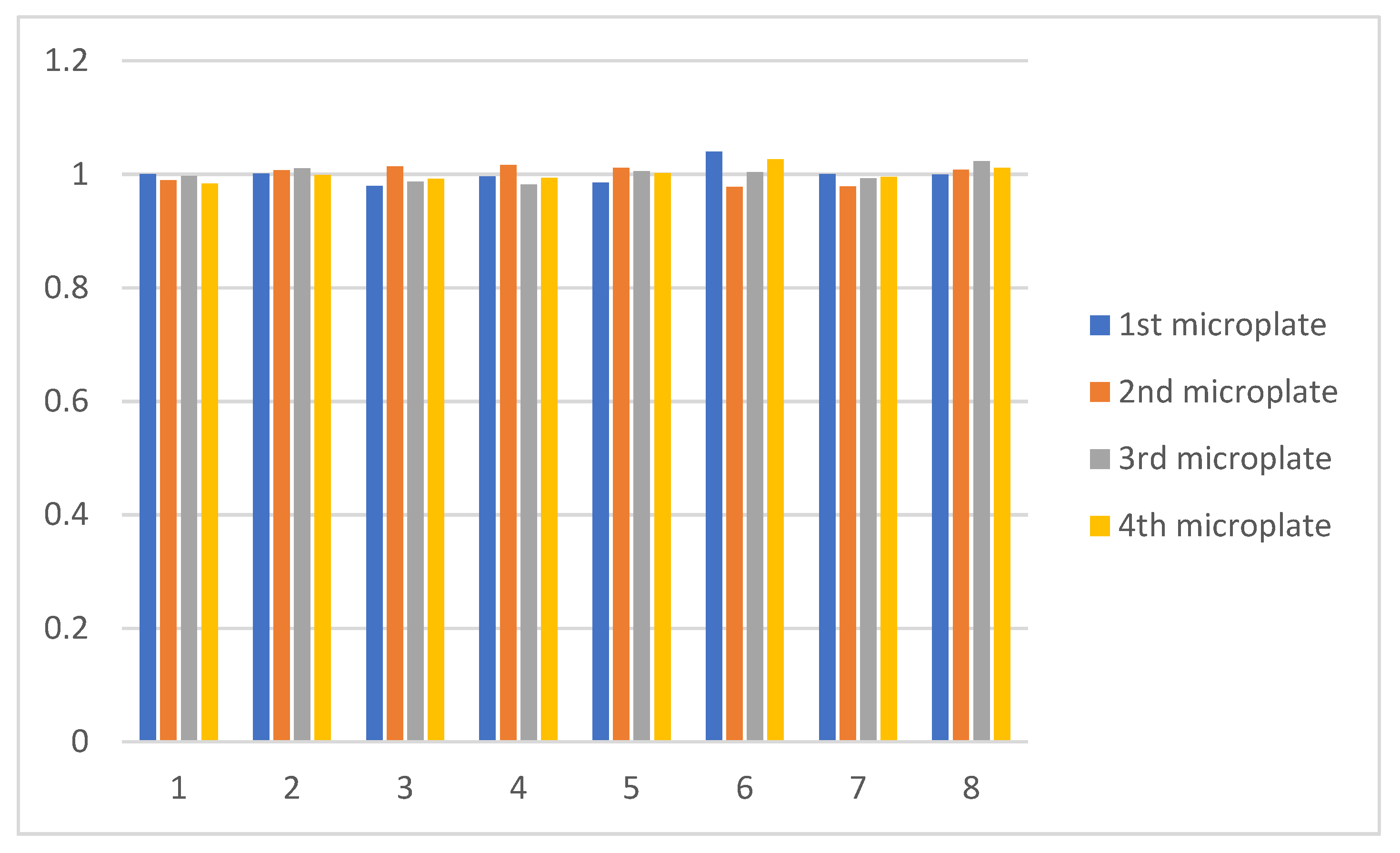
3.1.1. Flow Distribution in the Numbering-Up Microreactor

The performance of flow distribution at each layer of the numbering-up microreactor is discussed in this section. To compare the velocity distribution of each channel of the microplates, the average velocities are calculated using Equation (8). The maximum difference between the average velocities shows the standard deviation between the channels is defined as [ui(max) − ui(min)]/umean where the average velocity is given by:
u m e a n = 1 n i = 1 n u ( i )
The results from Figure 5 show the average velocities from the top to the bottom microplate for the gas flow. The performance of velocity distribution is good (nearly uniform) according to the figures, with the maximum difference between the average velocities to be less than 6%. Liquid flow showed similar results as those for the gas flow. Figure 6 shows the average velocities from the top to the bottom microplate for the liquid flow. The maximum difference between the average velocities was less than 3.3%. Comparing the two flows, the liquid flow showed better results on flow distribution within each layer of the numbering-up microreactor. The solution for the gas flow was checked from 1091688 to 4311048 degrees of freedom where negligible difference in the results was observed, therefore, the CFD results were mesh independent.

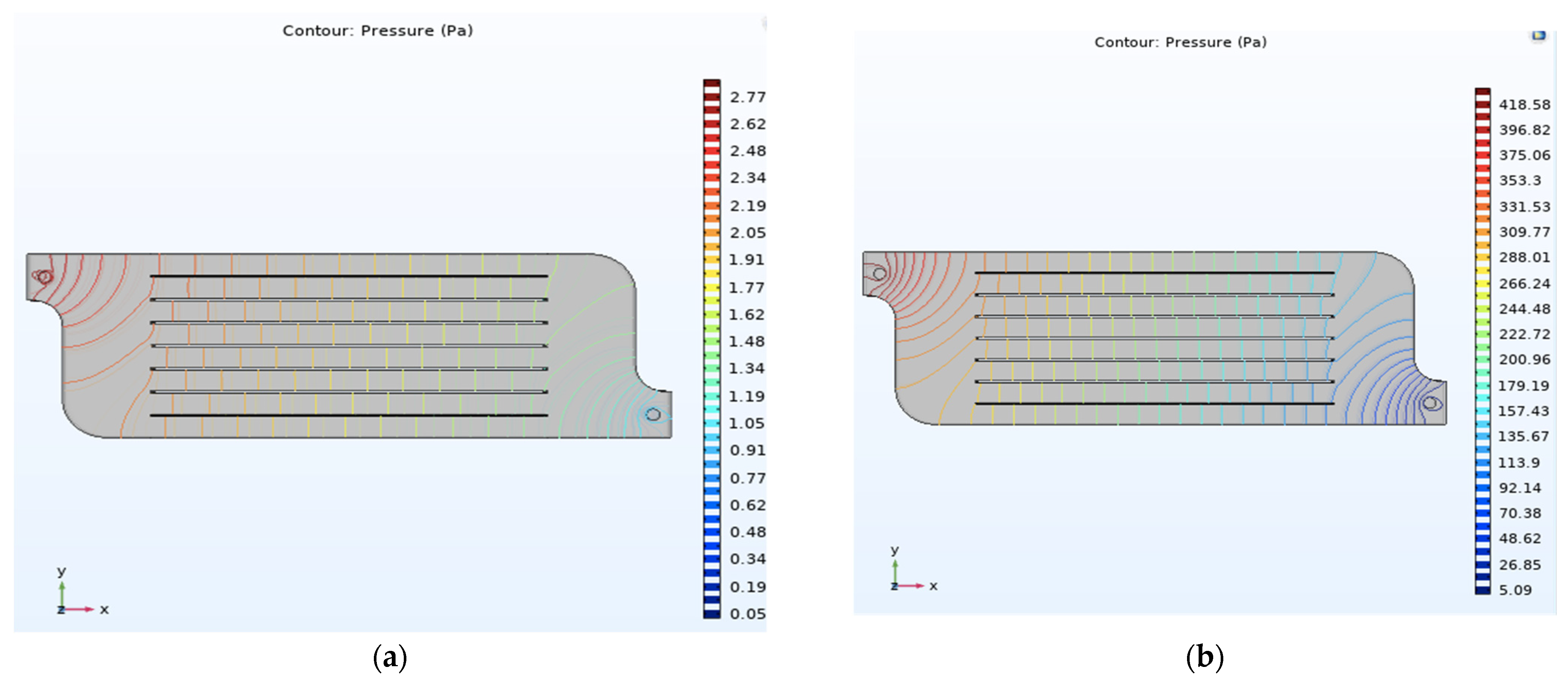
3.1.2. Pressure Profiles

As mentioned before, the pressure at the outlet of the microreactor was fixed at 0 N m2. Fluids tend to flow from high pressure levels to lower. The inlet pressure of the fluid for all the studied domains was 1 atm. Figure 7 shows the pressure profile for the gas and liquid flow, respectively. Each of the four microplates of the numbering-up microreactor had equal performance. According to the figures, the reduction of the pressure over the microplate is uniform and ensures the fact that the fluid is uniformly distributed over the microplates.

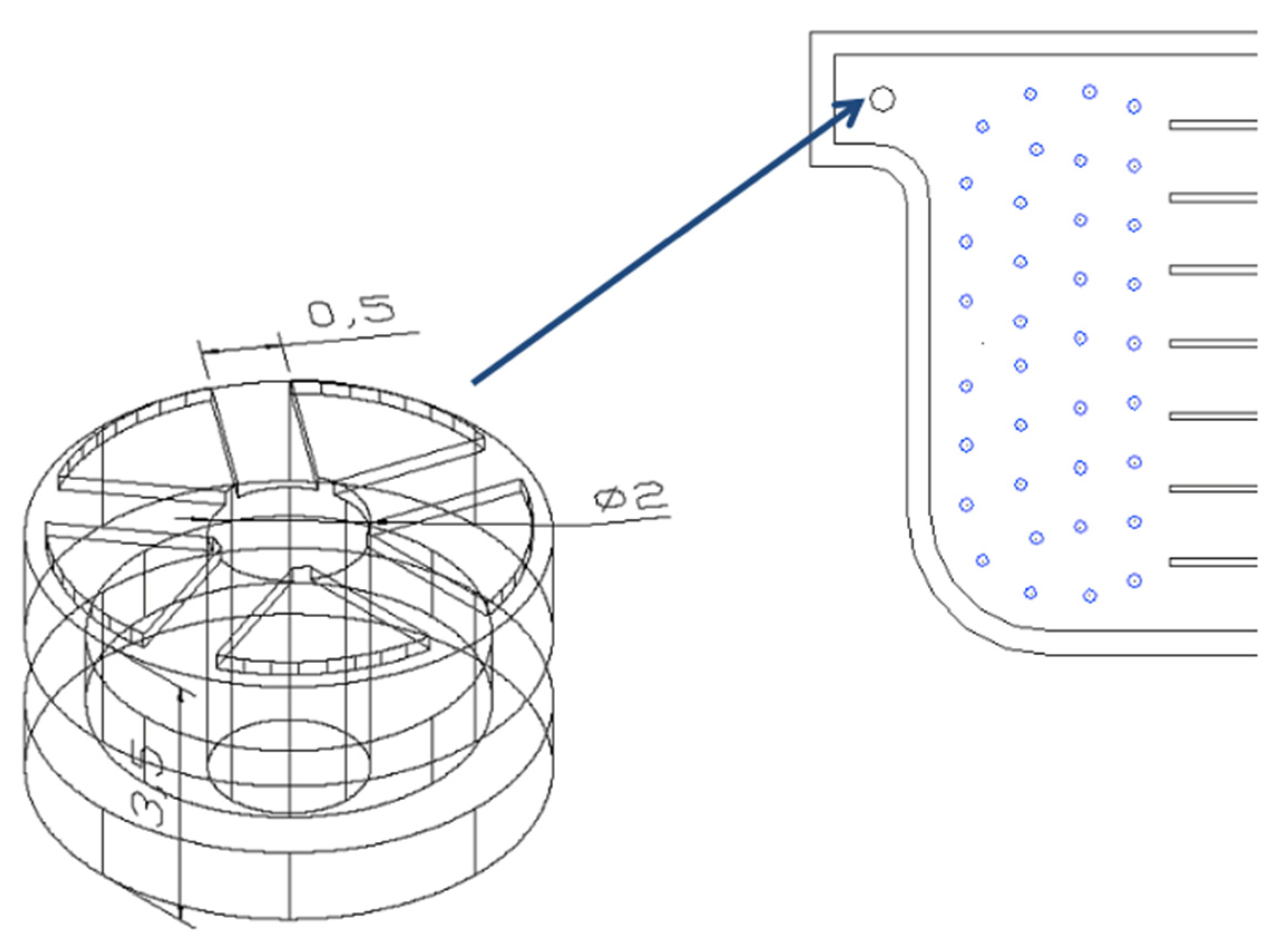
3.1.3. Effect of the Radius of Inlet and Outlet Tubes on the Flow Distribution

The effect of the radius of inlet and outlet tube on the distribution of the flow is examined. Inlet and outlet tubes were connected to the microplates and the fluid enters in each plate. The radius is increased from 1.5 mm to 2 mm to examine if optimal results could be observed. The remaining modelling parameters were kept constant. To examine the velocity distribution for each microplate the Equation (16) was used to calculate the mean velocities. Figure 8 shows the normalized velocity distribution from the top to the bottom microplate for the gas flow. Slightly better performance on uniformity was observed for the examined microplate when the radius of the tube was 2 mm, however better results were observed for the velocity distribution over the microplate as can be seen from Figure 7. The maximum difference of the average velocities was still less than 6%, but the average difference between the average velocities was slightly smaller when the radius of the tube was 2 mm.

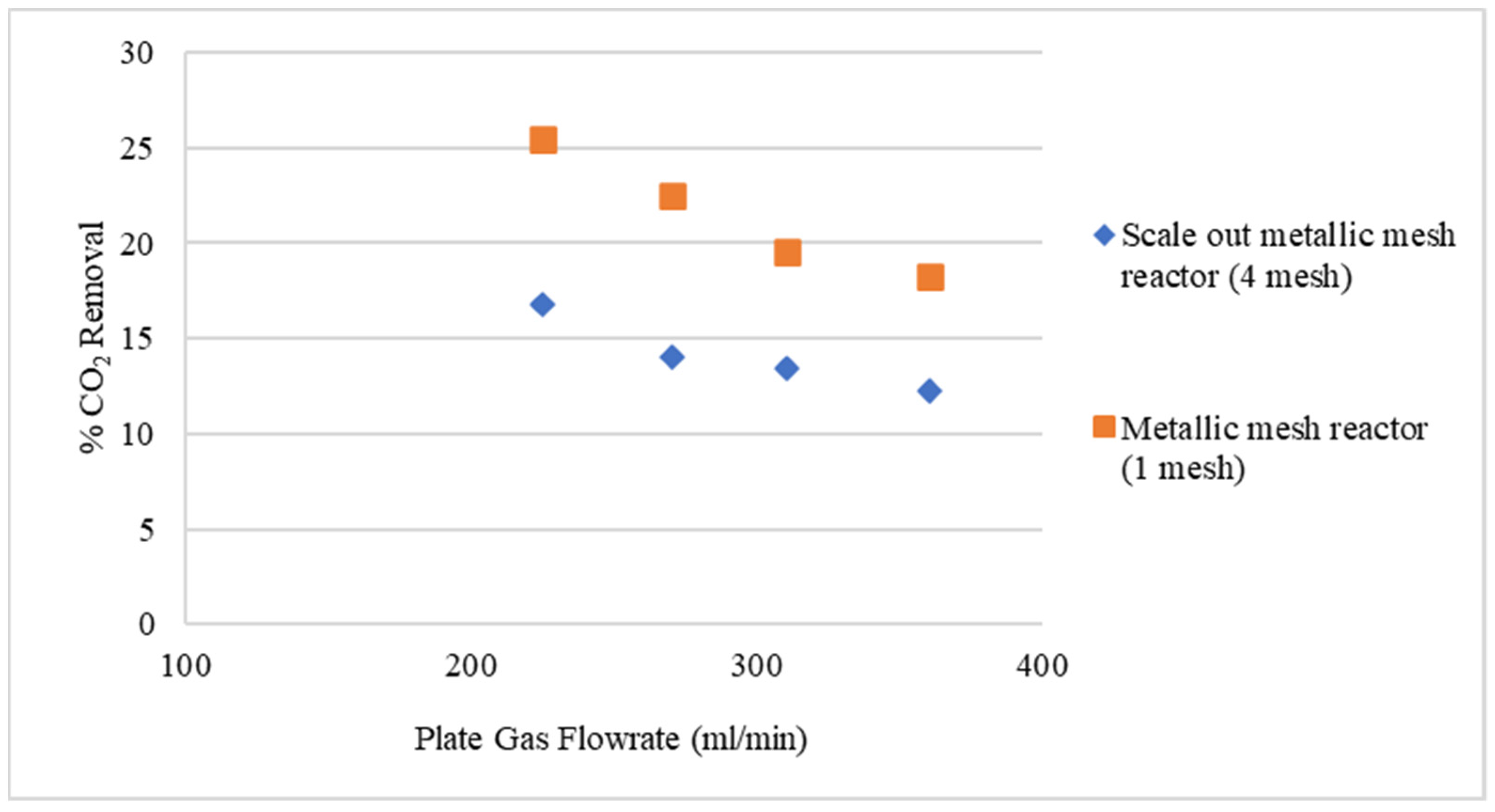
3.2. Experimental Results

The comparison between the two metallic mesh reactors (single and scale-out) for the absorption of CO2 in NaOH solution as a function of plate gas flowrates is shown in Figure 9. It is observed from the experimental data that the performance of the scale-out microreactor is relatively lower matched to the single channel reactor, even though it is expected that the performance of the two microreactors would be similar. The experimental results of the numbering-up microreactor do not demonstrate a good validation with the CFD simulations, implying that uneven flow distribution (maldistribution) can be the reason for a significantly lower performance with the experimental error to be below 5%. Based on the experimental results the metallic mesh reactor needs improvements in order to be used at industrial level. Furthermore, the CFD simulations demonstrate an even flow distribution to each plate and cannot realistically predict the difference in performance of the two configurations. The behavior of the scale out reactor led us to claim that the breakthrough of liquid in the gas phase or vice versa may take place in the second or in the third plate where visualization is not possible. At that point the breakthrough might cause the development of stagnant liquid in the gas phase which can potentially have an effect on the gas residence times, resulting in a diminished removal efficiency of CO2. Equal distribution can be guaranteed at each layer of the microreactor by ensuring each plate is perfectly made. In this case the gas and liquid chamber heights from the inlet to the outlet of each plate differed by approximately 10%. The imperfections on the fabrication of the plates can lead to uneven flow distribution at each plate of the reactor.
Yu et al. [33] studied the effects of flow distribution and mass transfer characteristics in a parallel microchannel contactor. The microchannel contactor consisted of two constructal distributers with a dichotomic tree structure which fed 16 microchannels, each with a hydraulic diameter of 667 µm. The experimental results showed that there was prominent maldistribution within the parallel microchannels, even though the CFD modelling studies demonstrated that there was no difference in results (even distribution). These results are consistent with those in the current work.

4. Conclusions

It is important to eliminate CO2 emissions in the atmosphere using the appropriate technologies. Through the years, membrane contactor technology has shown great potential to be used as a capture system for CO2. This study was mainly focused to examine the flow distribution of a numbering-up reactor using CFD models and the CO2 removal efficiency in a scale-out metallic mesh reactor.
In this work the flow distribution of a numbering-up microreactor was studied using 3D CFD models to examine if perfectly uniform flow distribution could be obtained and if it can be used on industrial scale by maximizing the throughput of CO2 removal. CFD simulations showed nearly uniform flow distribution for both gas and liquid flows. The pressure profile over the microplates showed that the pressure within the channels is uniformly decreased because fluids tend to flow from higher pressure levels to lower. The equal pressure, at every vertical point of the channels, signifies the flow uniformity within the channels at each vertical point of the microplate. Furthermore, experimental results were obtained from studies on CO2 removal, to compare to the single channel microreactor and the CFD models. Single and scale-out microreactors didn’t show similar results on CO2 removal as it was expected. The CFD simulations showed nearly uniform flow distribution in contrast to the experimental results which showed that uneven flow distribution might obtained leading to claim that the maldistribution is due to the imperfections on the fabrication of the plates. Furthermore, phase breakthrough of liquid into the gas phase or vice versa might be the reason of the discrepancy between the experimental results of the single mesh and the 4-mesh microreactor. Furthermore, the effect of the radius of the inlet and outlet tubes is examined on flow distribution. The aim of this examination is to optimize the velocity distribution by increasing the radius of the inlet and outlet tubes and compare to the distribution which was obtained at the first case. A slightly better performance on the flow distribution was achieved at each layer of the microreactor. Future studies will be focused on experimental breakthrough studies to improve the performance of the scale-out microreactor.

Author Contributions

Conceptualization, A.C.; methodology, E.H., G.M., S.H. and A.C.; software, E.H.; theoretical validation, E.H., G.M. and A.C.; formal analysis, E.H., G.M., A.C. and S.H.; resources, A.C.; writing—original draft preparation, E.H. and A.C.; writing—review and editing, E.H., S.H. and G.M.; visualization, E.H. and A.C.; supervision, A.C.; project administration, A.C. and G.M.; funding acquisition, A.C. All authors have read and agreed to the published version of the manuscript.

Funding

This research received no external funding.

Institutional Review Board Statement

Not applicable.

Informed Consent Statement

Not applicable.

Conflicts of Interest

The authors declare no conflict of interest.

References

  1. Ma, D.; Zhu, C.; Fu, T.; Yuan, X.; Ma, Y. An effective hybrid solvent of MEA/DEEA for CO2 absorption and its mass transfer performance in microreactor. Sep. Purif. Technol. 2020, 242, 116795. [Google Scholar] [CrossRef]
  2. Abolhasani, M.; Günther, A.; Kumacheva, E. Microfluidic Studies of Carbon Dioxide. Angew. Chem. Int. Ed. 2014, 53, 7992–8002. [Google Scholar] [CrossRef]
  3. Meisen, A.; Shuai, X. Research and development issues in CO2 capture. Energy Convers. Manag. 1997, 38, S37–S42. [Google Scholar] [CrossRef]
  4. Pires, J.C.M.; Martins, F.G.; Alvim-Ferraz, M.C.M.; Simões, M. Recent developments on carbon capture and storage: An overview. Chem. Eng. Res. Des. 2011, 89, 1446–1460. [Google Scholar] [CrossRef]
  5. Zhu, K.; Yao, C.; Liu, Y.; Chen, G. Theoretical approach to CO2 absorption in microreactors and reactor volume prediction. Chem. Eng. Process. Process. Intensif. 2020, 150, 107904. [Google Scholar] [CrossRef]
  6. Constantinou, A.; Ghiotto, F.; Lam, K.F.; Gavriilidis, A. Stripping of acetone from water with microfabricated and membrane gas–liquid contactors. Analyst 2014, 139, 266–272. [Google Scholar] [CrossRef] [PubMed]
  7. Sun, X.; Constantinou, A.; Gavriilidis, A. Stripping of acetone from isopropanol solution with membrane and mesh gas–liquid contactors. Chem. Eng. Process. Process. Intensif. 2011, 50, 991–997. [Google Scholar] [CrossRef]
  8. Ibrahim, M.H.; El-Naas, M.H.; Zhang, Z.; Van der Bruggen, B. CO2 Capture Using Hollow Fiber Membranes: A Review of Membrane Wetting. Energy Fuels 2018, 32, 963–978. [Google Scholar] [CrossRef]
  9. Hafeez, S.; Safdar, T.; Pallari, E.; Manos, G.; Aristodemou, E.; Zhang, Z.; Al-Salem, S.M.; Constantinou, A. CO2 capture using membrane contactors: A systematic literature review. Front. Chem. Sci. Eng. 2020, 15, 720–754. [Google Scholar] [CrossRef]
  10. Constantinou, A.; Barrass, S.; Pronk, F.; Bril, T.; Wenn, D.A.; Shaw, J.E.A.; Gavriilidis, A. CO2 absorption in a high efficiency silicon nitride mesh contactor. Chem. Eng. J. 2012, 207–208, 766–771. [Google Scholar] [CrossRef]
  11. Constantinou, A.; Barrass, S.; Gavriilidis, A. CO2 Absorption in Polytetrafluoroethylene Membrane Microstructured Contactor Using Aqueous Solutions of Amines. Ind. Eng. Chem. Res. 2014, 53, 9236–9242. [Google Scholar] [CrossRef]
  12. Constantinou, A.; Gavriilidis, A. CO2 Absorption in a Microstructured Mesh Reactor. Ind. Eng. Chem. Res. 2010, 49, 1041–1049. [Google Scholar] [CrossRef]
  13. Constantinou, A.; Barrass, S.; Gavriilidis, A. CO2 absorption in flat membrane microstructured contactors of different wettability using aqueous solution of NaOH. Green Process. Synth. 2018, 7, 471–476. [Google Scholar] [CrossRef]
  14. Rostami, S.; Keshavarz, P.; Raeissi, S. Experimental study on the effects of an ionic liquid for CO2 capture using hollow fiber membrane contactors. Int. J. Greenh. Gas. Control. 2018, 69, 1–7. [Google Scholar] [CrossRef]
  15. Pahlavanzadeh, H.; Darabi, M.; Ghaleh, V.R.; Bakhtiari, O. CFD Modeling of CO2 Absorption in Membrane Contactors Using Aqueous Solutions of Monoethanolamine–Ionic Liquids. Ind. Eng. Chem. Res. 2020, 59, 18629–18639. [Google Scholar] [CrossRef]
  16. Magnone, E. A performance comparison study of five single and sixteen blended amine absorbents for CO2 capture using ceramic hollow fiber membrane contactors. J. Ind. Eng. Chem. 2021, 100, 174–185. [Google Scholar] [CrossRef]
  17. Sohaib, Q. Rigorous non-isothermal modeling approach for mass and energy transport during CO2 absorption into aqueous solution of amino acid ionic liquids in hollow fiber membrane contactors. Sep. Purif. Technol. 2021, 254, 117644. [Google Scholar] [CrossRef]
  18. Griffini, G.; Gavriilidis, A. Effect of Microchannel Plate Design on Fluid Flow Uniformity at Low Flow Rates. Chem. Eng. Technol. 2007, 30, 395–406. [Google Scholar] [CrossRef]
  19. Mohammadi, M.; Jovanovic, G.N.; Sharp, K.V. Numerical study of flow uniformity and pressure characteristics within a microchannel array with triangular manifolds. Comput. Chem. Eng. 2013, 52, 134–144. [Google Scholar] [CrossRef]
  20. Tonomura, O.; Tanaka, S.; Noda, M.; Kano, M.; Hasebe, S.; Hashimoto, I. CFD-based optimal design of manifold in plate-fin microdevices. Chem. Eng. J. 2004, 101, 397–402. [Google Scholar] [CrossRef]
  21. Huang, C.-H.; Wang, C.-H.; Kim, S. A manifold design problem for a plate-fin microdevice to maximize the flow uniformity of system. Int. J. Heat Mass Transf. 2016, 95, 22–34. [Google Scholar] [CrossRef]
  22. Castedo, A.; Uriz, I.; Soler, L.; Gandía, L.M.; Llorca, J. Kinetic analysis and CFD simulations of the photocatalytic production of hydrogen in silicone microreactors from water-ethanol mixtures. Appl. Catal. B Environ. 2017, 203, 210–217. [Google Scholar] [CrossRef] [Green Version]
  23. Su, Y.; Kuijpers, K.; Hessel, V.; Noël, T. A convenient numbering-up strategy for the scale-up of gas–liquid photoredox catalysis in flow. React. Chem. Eng. 2016, 1, 73–81. [Google Scholar] [CrossRef]
  24. Togashi, S.; Miyamoto, T.; Sano, T.; Suzuki, M. Microreactor System Using the Concept of Numbering-Up. In New Trends in Fluid Mechanics Research; Zhuang, F.G., Li, J.C., Eds.; Springer: Berlin/Heidelberg, Germany, 2007; pp. 678–681. ISBN 978-3-540-75994-2. [Google Scholar]
  25. Kikutani, Y.; Hibara, A.; Uchiyama, K.; Hisamoto, H.; Tokeshi, M.; Kitamori, T. Pile-up glass microreactor. Lab. Chip 2002, 2, 193. [Google Scholar] [CrossRef]
  26. Su, Y.; Lautenschleger, A.; Chen, G.; Kenig, E.Y. A Numerical Study on Liquid Mixing in Multichannel Micromixers. Ind. Eng. Chem. Res. 2014, 53, 390–401. [Google Scholar] [CrossRef]
  27. Zhao, F.; Cambié, D.; Janse, J.; Wieland, E.W.; Kuijpers, K.P.L.; Hessel, V.; Debije, M.G.; Noël, T. Scale-up of a Luminescent Solar Concentrator-Based Photomicroreactor via Numbering-up. ACS Sustain. Chem. Eng. 2018, 6, 422–429. [Google Scholar] [CrossRef]
  28. Tonomura, O.; Taniguchi, S.; Nishi, K.; Nagaki, A.; Yoshida, J.; Hirose, K.; Ishizuka, N.; Hasebe, S. Blockage Detection and Diagnosis of Externally Parallelized Monolithic Microreactors. Catalysts 2019, 9, 308. [Google Scholar] [CrossRef] [Green Version]
  29. Cussler, E.L. Diffusion Mass Transfer in Fluid Systems; Cambridge University Press: Cambridge, UK, 2009. [Google Scholar]
  30. Versteeg, G.F.; van Swaaij, W.P.M. On the kinetics between CO2 and alkanolamines both in aqueous and non-aqueous solutions—I. Primary and secondary amines. Chem. Eng. Sci. 1988, 43, 573–585. [Google Scholar] [CrossRef] [Green Version]
  31. Nijsing, R.A.T.O.; Hendriksz, R.H.; Kramers, H. Absorption of CO2 in jets and falling films of electrolyte solutions, with and without chemical reaction. Chem. Eng. Sci. 1959, 10, 88–104. [Google Scholar] [CrossRef]
  32. Pohorecki, R.; Moniuk, W. Kinetics of reaction between carbon dioxide and hydroxyl ions in aqueous electrolyte solutions. Chem. Eng. Sci. 1988, 43, 1677–1684. [Google Scholar] [CrossRef]
  33. Yue, J.; Boichot, R.; Luo, L.; Gonthier, Y.; Chen, G.; Yuan, Q. Flow distribution and mass transfer in a parallel microchannel contactor integrated with constructal distributors. Aiche J. 2009, 56, 298–317. [Google Scholar] [CrossRef]
Figure 1. Schematic representation of the mathematical modelling domains with coordinates and boundaries.
Processes 09 01515 g001
Figure 2. Three-dimensional computational domain of the numbering-up microreactor.
Processes 09 01515 g002
Figure 3. (a) Scale-out metallic mesh reactor’s flow configuration (b) Picture of the components of the scale out metallic mesh reactor (c) Picture of assembled scale out metallic mesh reactor.
Processes 09 01515 g003
Figure 4. Diagram of the 0.5 mm acrylic insert displaying the location of insertion in the reactor.
Processes 09 01515 g004
Figure 5. Normalized velocity distribution from the 1st to the 4th microplate of the numbering-up microreactor at inlet gas flow rate Yg = 274.8 mL/min and Re = 76.32.
Processes 09 01515 g005
Figure 6. Normalized velocity distribution from the 1st to the 4th microplate of the numbering-up microreactor at inlet liquid flow rate Yl = 8.48 mL/min and Re = 19.54.
Processes 09 01515 g006
Figure 7. (a) Pressure profile of the numbering-up microreactor at inlet gas flow rate Yg = 274.8 mL/min Re = 76.32 and P0 = 1 atm, (b) Pressure profile of the numbering-up microreactor at inlet liquid flow rate Yl = 8.48 mL/min, Re = 19.54 and P0 = 1 atm.
Processes 09 01515 g007
Figure 8. Normalized velocity distribution from the 1st to the 4th microplate of the numbering-up microreactor for radius of inlet and outlet tube 2 mm, at inlet gas flow rate Yg = 488.58 mL/min and Re = 101.76.
Processes 09 01515 g008
Figure 9. Comparison between the scale out and metallic mesh reactors (1-mesh and 4-mesh) for CO2 absorption in 2 M NaOH solution. δG = 850 μm, δL = 200 μm, YCO2/YNaOH = 139.5, mesh porosity 15%.
Processes 09 01515 g009
Table 1. Parameters used for the CFD modelling study.
ParameterValueRef.
DCO2,g (m2/s) 1.64 × 10 5 [29]
DCO2,l (m2/s) 2.35 × 10 6 e x p ( 2119 T ) [30]
DNaOH,l (m2/s)1.64 × DCO2,l[31]
ρg (kg/m3)1.327[12]
μg (Pa.s)1.69 × 10⁻⁵[12]
ρl (kg/m3)1088[12]
μl (Pa.s)1.67 × 10⁻³[12]
Publisher’s Note: MDPI stays neutral with regard to jurisdictional claims in published maps and institutional affiliations.

