Article

Titanium Dioxide/Activated Carbon Electrode with Polyurethane Binder for the Removal of Indium Ions via Capacitive Deionization

1
Department of Cosmetic Science, Providence University, Taichung City 43301, Taiwan
2
Graduate Institute of Environmental Engineering, National Central University, Taoyuan City 32001, Taiwan
3
Biomedical Technology and Device Research Laboratories, Industrial Technology Research Institute, Hsinchu 310401, Taiwan
4
Material and Chemical Research Laboratories, Industrial Technology Research Institute, Hsinchu 310401, Taiwan
*
Author to whom correspondence should be addressed.
Processes 2021, 9(8), 1427; https://doi.org/10.3390/pr9081427
Submission received: 12 July 2021 / Revised: 8 August 2021 / Accepted: 14 August 2021 / Published: 18 August 2021
(This article belongs to the Section Environmental and Green Processes)

Abstract

:
The process of removing indium ions from aqueous solutions by applying capacitive deionization (CDI) is reported in this manuscript. First, a modified carbon material was prepared by incorporating titanium dioxide (TiO2) into activated carbon (AC). A microwave-assisted ionothermal synthesis (MAIS) method was used to produce evenly distributed nanostructured anatase TiO2 on the surface of AC. A polyurethane (PU) elastomer was then synthesized as the binder material instead of using conventional polyvinylidene fluoride (PVDF). By combining the aforementioned materials, a MAIS TiO2/AC-PU electrode was synthesized and applied to CDI tests. Scanning electron microscopy (SEM) was used to characterize the size and dispersion of the composites. For electrochemical properties, cyclic voltammetry (CV) and electrochemical impedance spectroscopy (EIS) were used to analyze the synthesized electrode. The performance of the prepared electrode during the CDI process was tested in different concentrations of indium solutions. It was discovered that the indium removal efficiency can be as high as 84% in 1 and 5 ppm of indium solutions.

1. Introduction

Capacitive deionization (CDI) is a technology known for removing charged ions from water [1,2,3]. Ideally, when the charged ions in the aqueous solution pass by the electrodes, only electrosorption of the ions to the electrodes occurs without any additional redox reaction. Therefore, when the potential of the electrodes is reversed, desorption of the ions takes place, leaving a fresh set of electrodes for reuse. The major application of CDI has always been desalination, especially for brackish water. However, CDI has gained much popularity recently due to the development of new nanosize carbon electrode materials which could greatly enhance desalination efficiency [4]. Other than salt removal, more applications have been found using CDI, including biomass hydrolyzate and heavy metal removal [5]. Huang et al. reported the removal of cadmium, lead, and chromium from water using CDI and they discovered that the applied voltage can influence the removal efficiency, and each metal had a different optimum applied voltage [6]. From their results, chromium and lead had a similar removal efficiency around 80%, whereas cadmium had only a low removal efficiency of 40%. Another study by Huang’s group reported the removal of copper ions using CDI [7]. Their research showed that the removal of copper ions did not interfere with salt ions, natural organic matter, or reactive silica dissolved in the aqueous solution. Furthermore, a recent study by Liu et al. demonstrated a wide application for CDI by removing metals including lead, copper, iron, cadmium, cobalt, nickel, zinc, magnesium, and calcium [8]. Highly porous N-doped graphene nanosheets were used as the electrode material, and the removal efficiencies were more than 90% for all the metal ions. In a recent article, recovery of indium ions was reported by using CDI technology [9]. The effectiveness of this recovering process was due to the acidic environment in the solution. The porous activated carbon electrode provided sufficient spacing for the cations, including In3+ and H+, to be electrosorbed in their capacity. According to the report, the deionization capacity of In3+ could be as high as 7.95 mg/g under optimum conditions. Therefore, the authors suggested that this process showed high potential in recovering indium ions from acidic solutions.
To the best of our knowledge, other than the aforementioned article, there is scarce literature on the removal of indium ions from aqueous solutions using CDI. Indium is a less abundant metal and can be found as a minor component in many mineral ores, such as zinc and copper ores. The major application of indium is for making indium tin oxide (ITO), which is a transparent conducting oxide widely used in flat panel displays and other electronic devices. Therefore, indium is often contained in the wastewater from the optoelectronics and semiconductor industry. Many reports about recovering or removing indium from the ITO etching wastewater [10,11,12,13]. Commercially, the main treatment for indium in ITO etching wastewater was by dilution, since after dilution, the indium concentration meets the effluent standards [14]. This method was considered simple and relatively inexpensive. However, it could consume a large volume of freshwater, which is currently a valuable natural resource. Therefore, alternative methods for removing indium from wastewater are still needed to be introduced.
In order to enhance the removal efficiency, two approaches were taken to modify the conventional CDI electrode. The first approach was to incorporate titanium dioxide into the surface and pores of the activated carbon. According to the literature, TiO2 has some special affinity with indium ions [15]. Zhang et al. discovered that TiO2 had a high adsorption efficiency of trace indium ions in pH 3.5–4.0 and a high desorption efficiency when pH was lower than 1.5 [16]. They also discovered that anatase TiO2 had a higher adsorption efficiency for indium than rutile TiO2. Hang et al. studied the adsorption of indium on nanosize TiO2 [17]. They also discovered that TiO2 had a high adsorption ratio and capacity to indium ions. Therefore, titanium dioxide and activated carbon composite (TiO2/AC) could have a high potential for efficient adsorption-desorption of indium ions. The other approach was to substitute the binder material since the binder of the electrode could also be influential to the electrode performance. One of the most widely used binder materials is polyvinylidene fluoride (PVDF) [18]. It is a hydrophobic polymer and can maintain the consistency of the carbon electrodes. However, cracking of the electrodes was often found when using the PVDF binder electrodes. Therefore, a polyurethane (PU) binder with stronger mechanical strength was developed. Less cracking was found when using CDI, and the electrode performance was maintained similar to the PVDF ones. In this manuscript, a microwave-assisted ionothermal synthesized (MAIS) nanostructured anatase titanium oxide/activated carbon composite was mixed with a polyurethane elastomer to prepare a MAIS TiO2/AC-PU electrode. The physical and electrochemical properties of the MAIS TiO2/AC-PU electrode were characterized. Applying the MAIS TiO2/AC-PU electrode for removing indium from the solution was tested, and the results indicated that the MAIS TiO2/AC-PU electrode is very suitable for the removal of indium ions.

2. Materials and Methods

2.1. Instrumentation

Inductively coupled plasma atomic emission spectroscopy (ICP-AES) was performed by iCAP 6300 (Thermo Fisher Scientific; Waltham, MA, USA) to analyze the concentration of the indium solutions. Scanning electron microscopy (SEM) was performed by JEOL JSE-6500F (Tokyo, Japan). The surface area and pore volume of the carbon material were measured by NOVA4000e and Autosorp MP1 instruments (Quantachrome; Boynton Beach, FL, USA). The Brunauer–Emmet–Teller (BET) method was used for analyzing the surface area, and the Barrett–Joyner–Halenda (BJH) model was used for determining the pore size and volume. Transmission electron microscopy (TEM) coupled with energy dispersive spectroscopy (EDS) were performed by a PHILIPS CM100 to measure particle size and metal content.

2.2. Preparation of Polyurethane Elastomer

The detailed synthesis procedure and material characterization of the polyurethane (PU) elastomer are provided in a previous report [19]. Polytetramethylene glycol (PTMEG; number average molecular weight = 2000) was purchased from Lidye Chemical, Taiwan. Glycerin monostearate diol (GMS) was purchased from First Chemical Manufacture, Taiwan. 2,4-toluene diisocyanate (TDI) was purchased from Tokyo Chemical Industry, Japan. N-methyl-2-pyrrolidone (NMP) was purchased from Sigma–Aldrich. All chemicals were used as received. In brief, PTMEG was first mixed with GMS and then TDI at 70 °C in NMP solvent to produce the prepolymer of PU. Followed by the moisture-curing step, the free isocyanate groups of the prepolymer reacted with water molecules. After complete reaction, the prepolymer transformed into a PU elastomer with a high molecular weight.

2.3. Microwave-Assisted Ionothermal Synthesis of TiO2/AC Composite

The detailed synthesis procedure and material characterization of the MAIS TiO2/AC composite are provided in a previous report [20]. Activated carbon (AC) was purchased from Formosa Plastics Corporation (Taiwan). Titanium tetraisopropoxide (TIP), isopropanol, and 1-butyl-3-methylimidazolium tetrafluoroborate ([Bmim]+[BF4]) ionic liquid were all purchased from Merck and used as received. In brief, MAIS contains two stages: a controlled sol-gel reaction and a subsequent ionic liquid-inducing crystallization. In a typical trial, 0.5 g of TIP, 2 g of AC, and 0.4 g of ionic liquid [Bmim]+[BF4] were mixed together with 200 mL of isopropanol using ultrasonication for dispersion. A small amount of water (less than 1 g) was added to the mixture for a sol-gel reaction. Afterward, the mixture was transferred into a microwave system with a power of 800 W, a frequency of 2.45 GHz for 30 min with reflux. After microwaving, the mixture was filtered and dried in an oven at 70 °C.
For crystallization in the second stage, as in a typical trial, 2 g of the dried sample powder from the first stage was mixed together with 80 mL of isopropanol, 7.2 g of ionic liquid [Bmim]+[BF4] and 9.6 g of water using ultrasonication. The mixture was then transferred into a microwave system with the same conditions mentioned above for 1 h. After microwaving, the mixture was again filtered and dried in an oven at 70 °C. The synthesized TiO2/AC composite had 8.2 wt% of TiO2. The percent loading of TiO2 in TiO2/AC composite was determined by conducting thermogravimetric analysis (TGA) (Perkin Elmer-TAC7/DX, Thermal Analysis Controller). While measuring the sample mass, the sample was heated from 30 to 800 °C to burn off any carbon-based material. The heating rate was 20 °C/min. The weight difference between the coated and uncoated samples was used to determine the percent loading of the TiO2. Moreover, the TiO2 had a particle size in a range of 7–12 nm, which was observed by TEM [21].

2.4. Fabrication of the Electrodes

Graphite powder (particle size: 3.5 micron) was purchased from Emaxwin, Taiwan. Polyvinylidene fluoride (PVDF) was purchased from Sigma–Aldrich. In a typical trial, the TiO2/AC composite, the binder (PU elastomer or PVDF), and graphite were mixed together in NMP solvent with a mass ratio of 8: 1: 1. After carefully stirring the mixture for 24 h, the slurry mixture was cast onto a titanium board by a doctor blade technique with a wet thickness of 300 micron. The coated electrode was then dried in an oven at 120 °C for 4 h.

2.5. Electrochemical Characterization

Indium nitrate (In(NO3)3; 99.9%) was purchased from Merck. Sodium chloride (NaCl) was purchased from Shimadzu. Cyclic voltammetry (CV) and electrochemical impedance spectroscopy (EIS) were conducted by an electrochemical workstation (CHI 614D; CH Instruments) and in a three-compartment cell. The capacitance of the prepared electrodes was determined by CV using an Ag/AgCl reference electrode, a platinum wire counter electrode, and a 0.5 M NaCl electrolyte. The scan rate was 10 mV/s from a potential range of −0.5 V–0.5 V, and the capacitance was measured accordingly. On the other hand, the EIS measurements were organized using an alternating current perturbation amplitude of 5 mV around the equilibrium potential of 0 V. The frequency range was from 1 mHz to 100 kHz.

2.6. CDI Performance

The detailed CDI apparatus setup is illustrated in a previous report [20]. In brief, a DC power supply was connected to a CDI cell equipped with a peristaltic pump. The sample feed was pumped to pass through the CDI cell and back to the feed for measurements and data analysis. The electrodes in the CDI cell were placed on both sides of the silicon packing and kept parallel with 0.2 cm apart. The electrode’s total opening area was 80 cm2 (5 cm × 8 cm × 2). In a typical trial, a sample solution of 100 mL was pumped into the CDI cell with an influent rate of 12 mL/min. A potential of 0.7 V was applied for a total adsorption time of 156 min. The pH value of the solution was monitored throughout the experiment. After the experiment was finished, the indium concentration was analyzed by ICP-AES.
For the calculation of the electrosorption capacity, the following equation is used:
E l e c t r o s o r p t i o n   c a p a c i t y   ( mg / g ) = ( C 0 C e ) V / m
where C0 is the initial concentration of iridium, Ce is the equilibrium concentration for iridium, V is the volume of the iridium solution, and m is the mass of the AC electrode.

3. Results

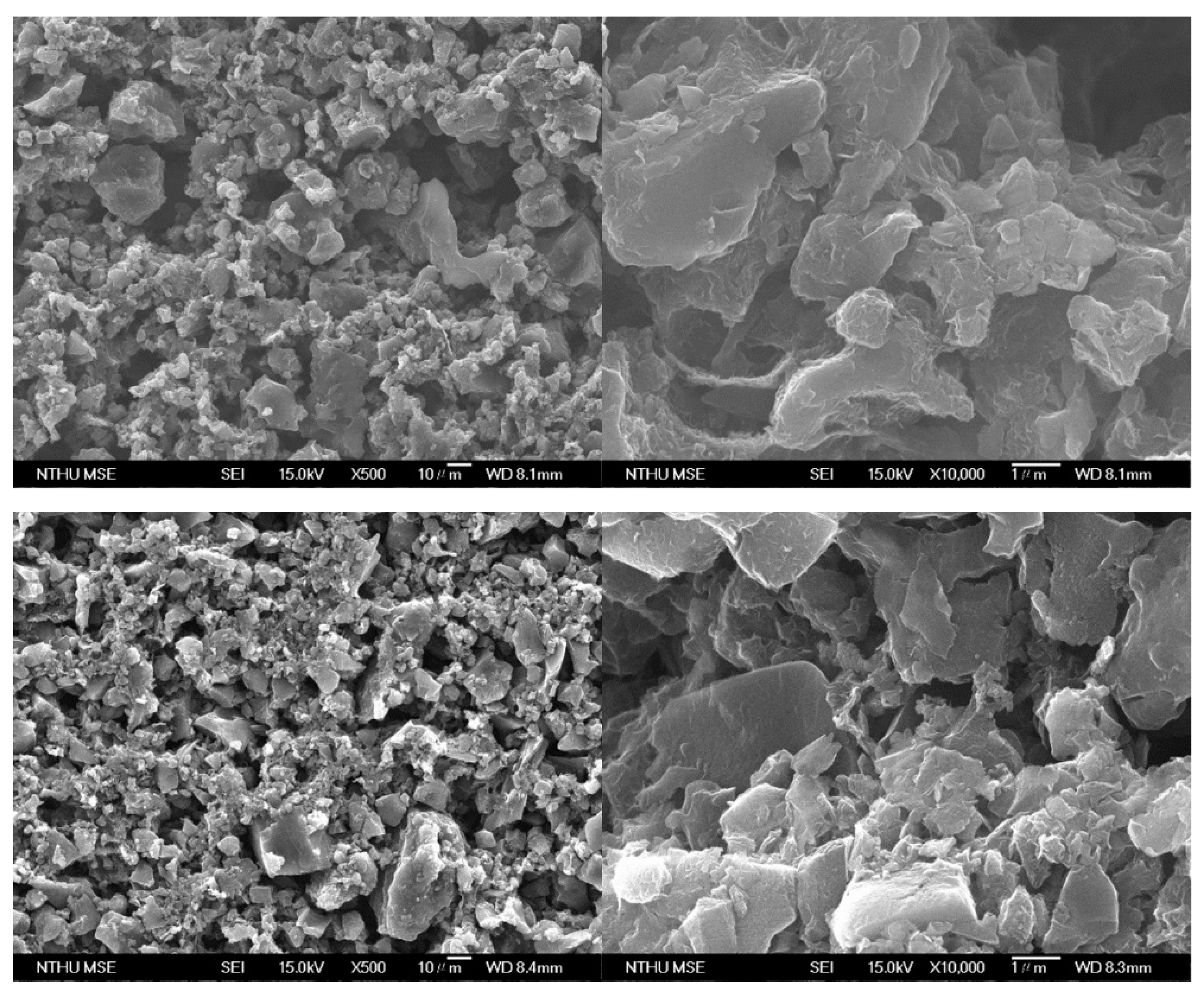
3.1. Characterization of the Electrode Materials

A petroleum coke-based activated carbon was selected as the AC material for our experiments due to its high surface area and large mesopore volume (2–50 nm). Table 1 shows the characteristics of the petroleum coke-based activated carbon from BET and BJH analysis. The mesopores in the activated carbon may help adsorb more ions due to the larger surface area. Additionally, some reports discovered that micropores are also very efficient for ion adsorption in CDI, and the AC material provides some [22,23].
The MAIS TiO2/AC-PU electrode was successfully prepared, and its scanning electron microscopy (SEM) images, together with the images of AC-PU, are shown in Figure 1. Both electrodes had similar SEM images, which were mostly showing the activated carbon and graphite particles. The TiO2 particles (7–12 nm) and AC were well-mixed with the PU binder and distributed evenly in the SEM images.

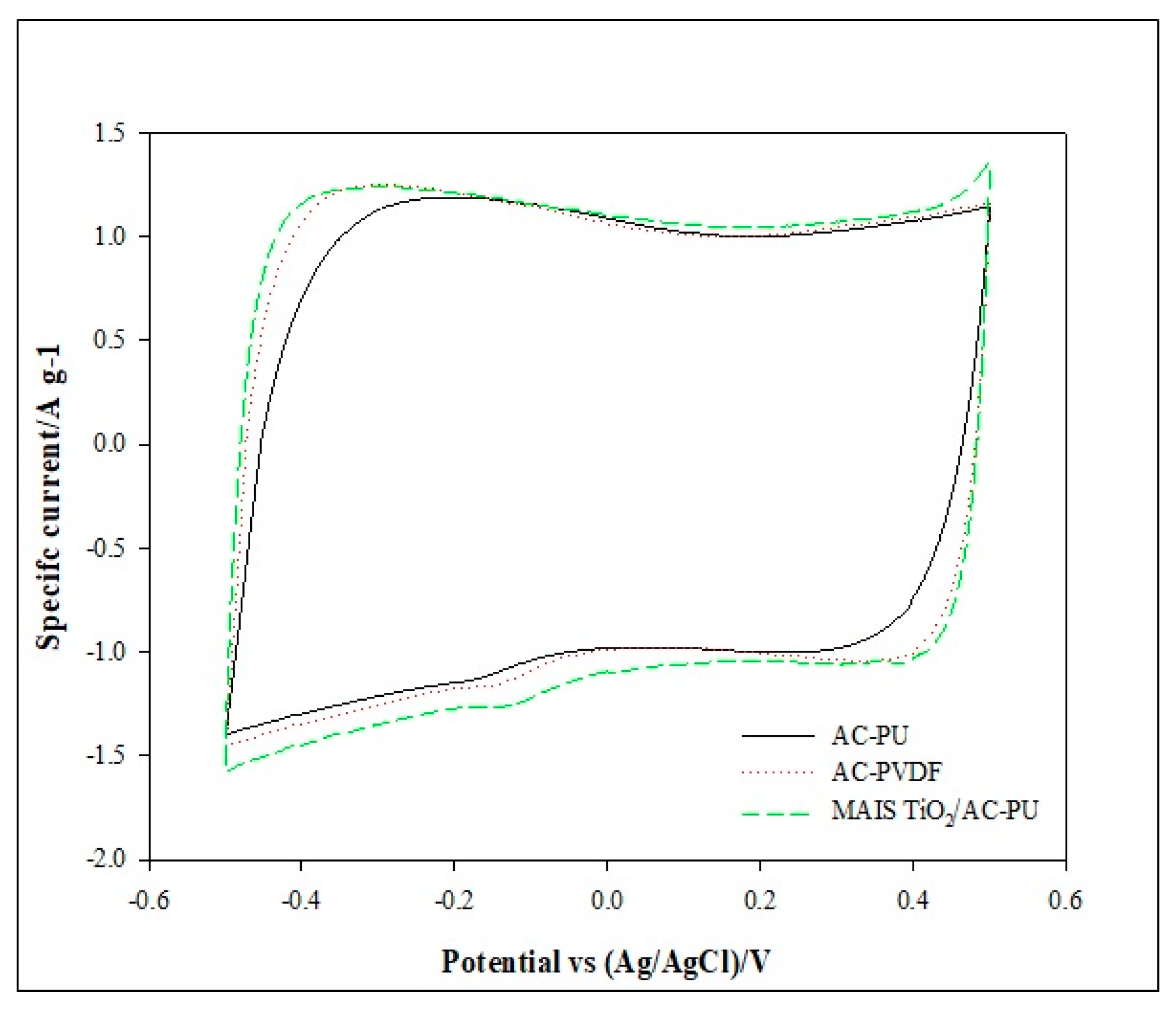
3.2. Cyclic Voltammetry Analysis of the Electrodes

The electrochemical properties of the MAIS TiO2/AC electrodes were first analyzed by cyclic voltammetry (CV), and their CV plots and average capacitance are shown in Figure 2 and Table 2, respectively. The CV plots were conducted in a 0.5 M NaCl aqueous electrolyte at a scan rate of 10 mV/s, and the plots showed rectangular-like curves attributable to an ideal double-layer capacitive behavior for the electrodes. Two activated carbon electrodes without incorporating TiO2 (AC-PU and AC-PVDF) were also tested for comparison. The results showed that the MAIS TiO2/AC electrodes had higher average capacitance than those without TiO2; this could be due to the dielectric constant of TiO2 (86–173), which is approximately an order of magnitude higher than those of activated carbon and graphite (10–15) [24]. In our previous study [20,21], the increase in electrode capacitance after TiO2 modification is due to the deposition of anatase TiO2 with a suitable amount of Ti–OH. Higher amounts of the Ti–OH can improve the surface wetting ability of the AC electrode, thereby facilitating the access ability of solution ions to the surface of the AC electrode and a higher uptake capacity of the ions on the electrode. Meanwhile, the resistivity measurement also indicates that the nanosized TiO2 lowers the resistivity of electrode material prepared by our MAIS synthesis method. Since the average capacitance of these electrodes is high, they all are suitable materials for being CDI electrodes.

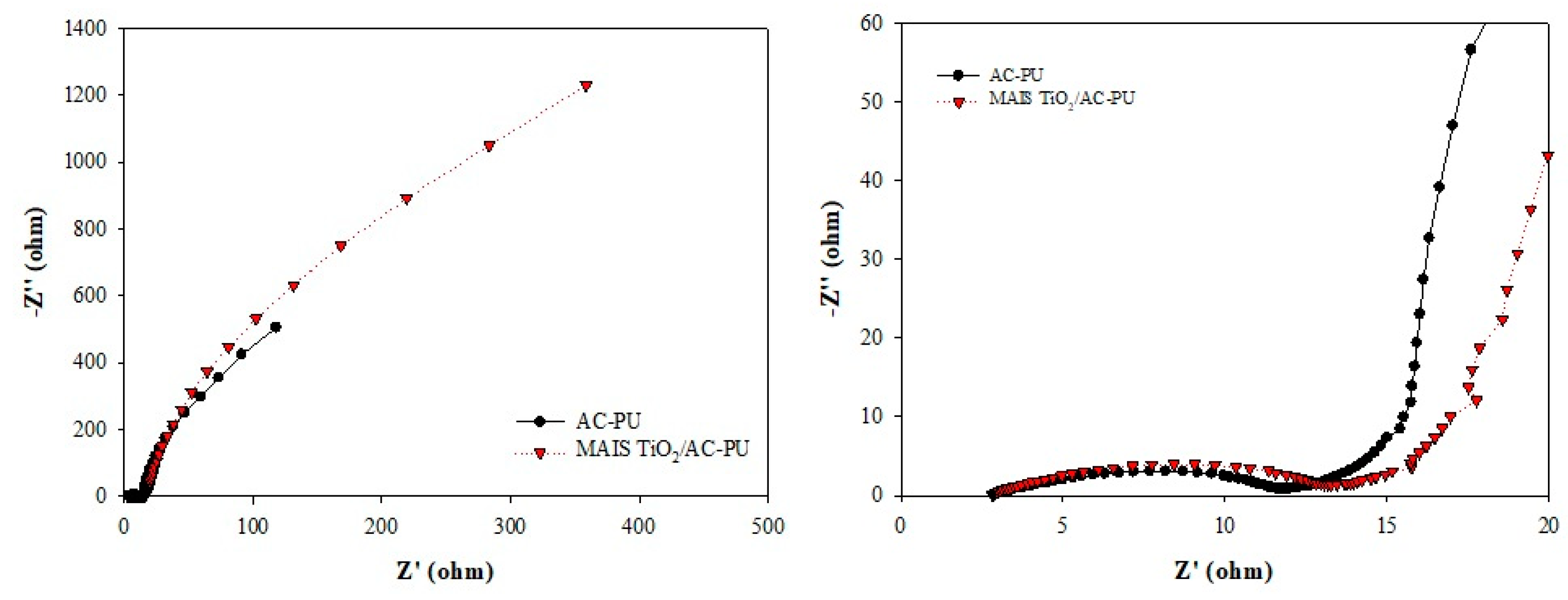
3.3. Electrochemical Impedance Spectroscopy Analysis of the Electrodes

Electrochemical impedance spectroscopy (EIS) was also applied to measure some of the electrochemical properties of the electrodes, and the Nyquist plots are shown in Figure 3. In Nyquist plots, the semicircle diameter can be assigned as the polarization resistance or, in other words, the contact resistance. Therefore, a shorter diameter for the semicircle is preferred since lower contact resistance is beneficial for electrical conduction. From our results, the MAIS TiO2/AC-PU and AC-PU electrodes had very similar semicircle diameters. This result indicated that incorporating TiO2 into the activated carbon only had a marginal effect on the resistance of the electrode; thus, the MAIS TiO2/AC-PU electrode could work just as efficiently as the AC-PU electrode.
The Bode plots for the different electrodes are shown in Figure 4, and the resistance and capacitive behaviors of the electrodes can also be compared. A phase angle closer to −90° indicates that the electrode has higher capacitance, whereas a phase angle closer to 0° signifies that the electrode has a higher resistance. From our results, the maximum phase angles (closer to −90°) were observed at a lower frequency range for both electrodes with the AC-PU electrode had a slightly higher phase angle than that of the MAIS TiO2/AC-PU electrode. Therefore, the results from the Bode and Nyquist plots confirmed with each other that both kinds of electrodes were fabricated well enough for CDI applications.

3.4. CDI Performance of the MAIS TiO2/AC-PU Electrode

The CDI performance of the MAIS TiO2/AC electrode was tested by batch adsorption experiments, and the indium removal efficiency and electrosorption capacity was calculated accordingly. From Table 3, the MAIS TiO2/AC-PU electrode had high indium removal efficiency (about 80% or more) when the initial indium concentration was in the range of 1–10 ppm. As the initial concentration of indium increased, the removal efficiency decreased since the adsorption sites in the electrode material were limited. On the other hand, the electrosorption capacity increased with the increase in the initial concentration of indium. However, the electrosorption capacity reached a plateau in higher concentration conditions, and this adsorption phenomenon was speculated to follow the Langmuir adsorption model during lower concentrations (1–10 ppm) and the Freundlich model during higher concentrations (>10 ppm). Also, the results are quite comparable with a relatively similar work in the literature by Khan et al. [25]. In their study, a carbon nanotube-PU composite was used as a CDI electrode to remove lead, a post-transition metal resembling indium, from an aqueous solution. The carboxyl group on the carbon nanotube reacted with the amide group of PU, and the dispersibility of the carbon nanotube increased in the solution, which also improved the lead adsorption. Nevertheless, the lead removal rate in neutral and acidic solutions was reported to be approximately 97% and 85%, respectively.
AC-PU and AC-PVDF, which are AC electrodes without TiO2, were compared with the CDI tests. However, precipitation of indium and its hydroxide occurred during the CDI process. Moreover, the pH of the solutions increased rapidly and even changed from acidic into weak basic for both AC-PU and AC-PVDF electrodes. It should be noted that precipitation can be avoided when the initial pH is less than 3 for the AC-PU and AC-PVDF electrodes. However, a stronger acidic solution would be more difficult to handle due to safety issues. According to the Pourbaix diagram, or potential/pH diagram, in an acidic solution with 0.7 V, most indium ions are in the form of In3+ while some [In(OH)]2+ may also be formed near neutral conditions [26]. In a basic solution with 0.7 V, the indium starts to form In(OH)3 and precipitate. If precipitation of indium and its hydroxide occurred during the CDI process, it might require extra treatments to remove the precipitation. Generally, the pH value should be stable throughout the whole CDI process [7]. In our case, the indium solutions using the MAIS TiO2/AC-PU electrode were all maintained at an acidic pH ranging from 3.5 to 5.6, and no precipitation or hydrolysis was observed during the process. It is speculated that the TiO2 particles may have stabilized the indium ions during the CDI adsorption process since TiO2 is reported to have special electrical and chemical properties when doping indium [27,28,29]. The stabilization of TiO2 to indium may also be related to stabilizing the solution’s pH value. Therefore, the MAIS TiO2/AC-PU electrode is suitable for indium removal using CDI.

4. Conclusions

The MAIS TiO2/AC-PU demonstrated in this report that it could be a very effective electrode for indium removal using CDI. The PU binder can help improve the removal efficiency, and it can be a good alternative to the conventional PVDF binder. Moreover, using the MAIS TiO2/AC-PU electrode could result in steadier pH control of the solution than using a conventional electrode; this could help prevent precipitation of the indium. It is very promising to apply CDI to remove indium from industrial wastewater as this report’s removal efficiency could be as high as 84%. Based on our results, improving the selectivity and efficiency of the electrode is critical for CDI applications, and it will be our priority task in the near future.

Author Contributions

Conceptualization, S.-H.C. and M.-C.C.; methodology, R.-Y.H. (Ren-Yang Horng) and M.-C.C.; formal analysis, P.-I.L. and R.-Y.H. (Ren-Yang Horng); investigation, C.H.Y., M.-C.C. and S.-H.C.; data curation, P.-I.L. and R.-Y.H. (Ren-Yang Horng); writing—original draft preparation, C.H.Y. and M.-C.C.; writing—review and editing, C.H.Y. and S.-H.C.; project administration, R.-Y.H. (Ren-Yi Huang). All authors have read and agreed to the published version of the manuscript.

Funding

This research was funded by the Ministry of Science and Technology, grant number 101-2221-E-324-013-MY3 and by TPC-(061)-(090001901).

Institutional Review Board Statement

Not applicable.

Informed Consent Statement

Not applicable.

Data Availability Statement

Not applicable.

Acknowledgments

The authors would like to thank L.C. Chung of ITRI for the research support.

Conflicts of Interest

The authors declare no conflict of interest.

References

  1. Porada, S.; Zhao, R.; van der Wal, A.; Presser, V.; Biesheuvel, P.M. Review on the science and technology of water desalination by capacitive deionization. Prog. Mater. Sci. 2013, 58, 1388–1442. [Google Scholar] [CrossRef] [Green Version]
  2. AlMarzooqi, F.A.; Al Ghaferi, A.A.; Saadat, I.; Hilal, N. Application of capacitive deionisation in water desalination: A review. Desalination 2014, 342, 3–15. [Google Scholar] [CrossRef]
  3. Zhang, X.; Zuo, K.; Zhang, X.; Zhang, C.; Liang, P. Selective ion separation by capacitive deionization (CDI) based technologies: A state-of-the-art review. Environ. Sci. Water Res. Technol. 2020, 6, 243–257. [Google Scholar] [CrossRef]
  4. Thamilselvan, A.; Nesaraj, A.S.; Noel, M. Review on carbon-based electrode materials for application in capacitive deionization process. Int. J. Environ. Sci. Technol. 2016, 13, 2961–2976. [Google Scholar] [CrossRef]
  5. Suss, M.E.; Porada, S.; Sun, X.; Biesheuvel, P.M.; Yoon, J.; Presser, V. Water desalination via capacitive deionization: What is it and what can we expect from it? Energy Environ. Sci. 2015, 8, 2296–2319. [Google Scholar] [CrossRef] [Green Version]
  6. Huang, Z.; Lu, L.; Cai, Z.; Ren, Z.J. Individual and competitive removal of heavy metals using capacitive deionization. J. Hazard. Mater. 2016, 302, 323–331. [Google Scholar] [CrossRef] [PubMed]
  7. Huang, S.Y.; Fan, C.S.; Hou, C.H. Electro-enhanced removal of copper ions from aqueous solutions by capacitive deionization. J. Hazard. Mater. 2014, 278, 8–15. [Google Scholar] [CrossRef]
  8. Liu, L.; Guo, X.; Tallon, R.; Huang, X.; Chen, J. Highly porous N-doped graphene nanosheets for rapid removal of heavy metals from water by capacitive deionization. Chem. Commun. 2017, 53, 881–884. [Google Scholar] [CrossRef] [Green Version]
  9. Shen, Y.Y.; Wu, S.W.; Hou, C.H. Exploring the electrosorption selectivity and recovery of indium ions with capacitive deionization in acidic solution. J. Colloid Interface Sci. 2021, 586, 819–829. [Google Scholar] [CrossRef]
  10. Liu, H.M.; Wu, C.C.; Lin, Y.H.; Chiang, C.K. Recovery of indium from etching wastewater using supercritical carbon dioxide extraction. J. Hazard. Mater. 2009, 172, 744–748. [Google Scholar] [CrossRef] [PubMed]
  11. Swain, B.; Mishra, C.; Hong, H.S.; Cho, S.S. Treatment of indium-tin-oxide etching wastewater and recovery of In, Mo, Sn and Cu by liquid–liquid extraction and wet chemical reduction: A laboratory scale sustainable commercial green process. Green Chem. 2015, 17, 4418–4431. [Google Scholar] [CrossRef]
  12. Hasegawa, H.; Rahman, I.M.M.; Umehara, Y.; Sawai, H.; Maki, T.; Furusho, Y.; Mizutani, S. Selective recovery of indium from the etching waste solution of the flat-panel display fabrication process. Microchem. J. 2013, 110, 133–139. [Google Scholar] [CrossRef] [Green Version]
  13. Chou, W.S.; Shen, Y.H.; Yang, S.J.; Hsiao, T.C.; Huang, L.F. Recovery of indium from the etching solution of indium tin oxide by solvent extraction. Environ. Prog. Sustain. Energy 2016, 35, 758–763. [Google Scholar] [CrossRef] [Green Version]
  14. Hsu, K.U.; Hu, Y.T.; Chu, C.P.; Chung, Y.R. Current investigation and control of new pollutants in wastewater and recycled water (translated from Chinese). Sinotech Eng. 2014, 123, 3–15. [Google Scholar]
  15. Atanacio, A.J.; Bak, T.; Nowotny, J. Effect of indium segregation on the surface versus bulk chemistry for indium-doped TiO2. ACS Appl. Mater. Interfaces 2012, 4, 6626–6634. [Google Scholar] [CrossRef]
  16. Zhang, L.; Wang, Y.; Guo, X.; Yuan, Z.; Zhao, Z. Separation and preconcentration of trace indium(III) from environmental samples with nanometer-size titanium dioxide. Hydrometallurgy 2009, 95, 92–95. [Google Scholar] [CrossRef]
  17. Hang, Y.; Qin, Y.; Jiang, Z.; Hu, B. Study on the adsorption behavior of Ga, In and Tl on nanometer-size titanium dioxide by ICP-AES. Spectrosc. Spect. Anal. 2005, 25, 1131–1134. [Google Scholar]
  18. Choi, J.Y.; Choi, J.H. A carbon electrode fabricated using a poly(vinylidene fluoride) binder controlled the Faradaic reaction of carbon powder. J. Ind. Eng. Chem. 2010, 16, 401–405. [Google Scholar] [CrossRef]
  19. Fang, C.H.; Liu, P.I.; Chung, L.C.; Shao, H.; Ho, C.H.; Chen, R.S.; Fan, H.T.; Liang, T.M.; Chang, M.C.; Horng, R.Y. A flexible and hydrophobic polyurethane elastomer used as binder for the activated carbon electrode in capacitive deionization. Desalination 2016, 399, 34–39. [Google Scholar] [CrossRef]
  20. Liu, P.I.; Chung, L.C.; Shao, H.; Liang, T.M.; Horng, R.Y.; Ma, C.C.M.; Chang, M.C. Microwave-assisted ionothermal synthesis of nanostructured anatase titanium dioxide/activated carbon composite as electrode material for capacitive deionization. Electrochim. Acta 2013, 96, 173–179. [Google Scholar] [CrossRef]
  21. Liu, P.I.; Chung, L.C.; Ho, C.H.; Shao, H.; Liang, T.M.; Horng, R.Y.; Chang, M.C.; Ma, C.C.M. Effects of activated carbon characteristics on the electrosorption capacity of titanium dioxide/activated carbon composite electrode materials prepared by a microwave-assisted ionothermal synthesis method. J. Colloid Interface Sci. 2015, 446, 352–358. [Google Scholar] [CrossRef] [PubMed]
  22. Porada, S.; Borchardt, L.; Oschatz, M.; Bryjak, M.; Atchison, J.S.; Keesman, K.J.; Kaskel, S.; Biesheuvel, P.M.; Presser, V. Direct prediction of the desalination performance of porous carbon electrodes for capacitive deionization. Energy Environ. Sci. 2013, 6, 3700–3712. [Google Scholar] [CrossRef] [Green Version]
  23. Zhao, S.; Yan, T.; Wang, Z.; Zhang, J.; Shi, L.; Zhang, D. Removal of NaCl from saltwater solutions using micro/mesoporous carbon sheets derived from watermelon peel via deionization capacitors. RSC Adv. 2017, 7, 4297–4305. [Google Scholar] [CrossRef] [Green Version]
  24. Engineering ToolBox. Relative Permittivity—the Dielectric Constant. 2010. Available online: https://www.engineeringtoolbox.com/relative-permittivity-d_1660.html (accessed on 6 August 2021).
  25. Khan, T.A.; Nazir, M.; Khan, E.A.; Riaz, U. Multiwalled carbon nanotube-polyurethane (MWCNT/PU) composite adsorbent for safranin T and Pb(II) removal from aqueous solution: Batch and fixed-bed studies. J. Mol. Liq. 2015, 212, 467–479. [Google Scholar] [CrossRef]
  26. Pourbaix, M. Atlas of Electrochemical Equilibria, 2nd ed.; National Association of Corrosion Engineers: Houston, TX, USA, 1974; pp. 436–442. [Google Scholar]
  27. Nowotny, J.; Alim, M.A.; Bak, T.; Atanacio, A.J.; Malik, A. Electrical properties and defect chemistry of indium-doped TiO2. Thermoelectric power. Ionics 2015, 21, 2019–2029. [Google Scholar] [CrossRef] [Green Version]
  28. Nowotny, J.; Bak, T.; Ionescu, M.; Alim, M.A. Electrical Properties and Defect Chemistry of In-Doped TiO2 in Terms of the Jonker Formalism. J. Phys. Chem. A 2015, 119, 4032–4040. [Google Scholar] [CrossRef] [PubMed]
  29. Atanacio, A.J.; Alim, M.A.; Bak, T.; Ionescu, M.; Nowotny, J. Segregation in Titanium Dioxide Co-Doped with Indium and Niobium. J. Am. Ceram. Soc. 2017, 100, 419–428. [Google Scholar] [CrossRef] [Green Version]
Figure 1. Scanning electron microscopy (SEM) of the electrodes: top left is AC-PU (× 500); top right is AC-PU (× 10,000); bottom left is MAIS TiO2/AC-PU (× 500), and bottom right is MAIS TiO2/AC-PU (× 10,000). (For each image, scale bars on the left are 10 microns and on the right are 1 micron).
Processes 09 01427 g001
Figure 2. Cyclic voltammetry (CV) plots of different electrodes in 0.5 M NaCl aqueous electrolyte at a scan rate of 10 mV/s.
Processes 09 01427 g002
Figure 3. Nyquist plots for the electrodes: left is whole region; right is close-up of the near region.
Processes 09 01427 g003
Figure 4. Bode plots for the electrodes.
Processes 09 01427 g004
Table 1. Characteristics of the petroleum coke-based activated carbon.
Specific Surface AreaTotal Pore VolumeMicropore Volume (<2 nm)Mesopore Volume (2–50 nm)
AC2715 m2/g1.55 cm3/g0.06 cm3/g1.10 cm3/g
Table 2. The average capacitance of the different electrodes 1.
CDI ElectrodeAverage Capacitance (F/g)
AC-PU122.4 ± 4.3
AC-PVDF129.6 ± 2.3
MAIS TiO2/AC-PU135.2 ± 4.0
1 Electrolyte: 0.5 M NaCl.
Table 3. Removal efficiency of indium ions using different electrode materials in batch experiments of CDI.
Electrode TypeInitial Concentration (ppm)Final Concentration (ppm)Final pH 1Electrosorption Capacity (mg/g)Removal Efficiency (%)
MAIS TiO2/AC-PU004.6n/an/a
MAIS TiO2/AC-PU1.20.24.70.484.8
MAIS TiO2/AC-PU5.30.85.62.584.3
MAIS TiO2/AC-PU10.32.14.54.679.6
MAIS TiO2/AC-PU23.513.63.95.442.2
MAIS TiO2/AC-PU48.830.33.57.537.9
AC-PU10.2precipitated7.8n/an/a
AC-PVDF12.3precipitated7.5n/an/a
1 All initial pH = 3.5.
Publisher’s Note: MDPI stays neutral with regard to jurisdictional claims in published maps and institutional affiliations.

