Article

Fractional Modeling and Characteristic Analysis of Hydro-Pneumatic Suspension for Construction Vehicles

1
School of Mechanical and Automotive Engineering, Qilu University of Technology (Shandong Academy of Sciences), Jinan 250353, China
2
College of Mechanical and Electronic Engineering, Shandong University of Science and Technology, Qingdao 266590, China
3
School of Mathematics and Statistics, Qilu University of Technology (Shandong Academy of Sciences), Jinan 250353, China
*
Author to whom correspondence should be addressed.
Processes 2021, 9(8), 1414; https://doi.org/10.3390/pr9081414
Submission received: 26 July 2021 / Revised: 9 August 2021 / Accepted: 11 August 2021 / Published: 16 August 2021

Abstract

:
The motion differential equation of hydro-pneumatic suspension is established to describe the vibration characteristics for a certain type of construction vehicle. The output force was deduced from the suspension parameters. Based on the suspension characteristics of a multi-phase medium, fractional calculus theory was introduced, and its fractional Bagley–Torvik equation was formed. The numerical computation by a low-pass filter of the Oustaloup algorithm was performed. The numerical solution of a nonlinear fractional equation was obtained to investigate the vibration characteristics of the suspension fractional system. Through the building of an equal-ratio test platform and simulation model, the fractional- integer-order model simulation and experimental data were compared. When the fractional order is 0.9, it better describes the motion characteristics of suspension system. The experiments show that the experimental data can fit the fractional-order system model well, and thereby prove the model on a hydro-pneumatic suspension system.

1. Introduction

Hydro-pneumatic suspension has good nonlinear elastic characteristics and damping characteristics, and is widely used in mining dump trucks. Its characteristics have an important influence on the ride comfort and handling stability of vehicles. Domestic and foreign scholars have performed a lot of research on the modeling and characteristics of hydro-pneumatic suspension. Michele [1] and Gao [2] modeled and simulated the active hydro-pneumatic suspension of heavy vehicles. Sun Tao et al. [3] established a long-hole turbulence damping model of a hydro-pneumatic suspension and simulated its stiffness and damping characteristics. Wang Hanping [4] conducted a modeling study based on the theory of heat transfer. The mathematical model of the hydro-pneumatic suspension established by the above research takes into account the nonlinear characteristics of the gas and the seal. When considering the compressibility of oil, it is mostly considered that the bulk elastic modulus changes after the oil contains gas. Therefore, a number of assumptions were made [5,6,7,8,9], such as keeping the gas quality constant, no leakage, no deformation, etc. The research by Huang Xiaxu et al. [10] also showed that the effect of gas dissolution and the compressibility of oil cannot be ignored in the process of hydro-pneumatic suspension design and research.
The work of the actual suspension system is much more complicated, not only related to its own parameters, but it is also affected by the relative displacement of its parts, the wear condition of the parts, the viscosity of the oil, and the flow and compressibility of the oil in the hydro-pneumatic suspension. It can be seen that there are too many assumptions in many of the above studies. Always focusing on the changes in certain parameters and the impact on the suspension system, or by adding calculation items to ensure the calculation accuracy, it is difficult to achieve an accurate and rapid description on the whole.
The traditional integer-order derivative model requires the introduction of multiple derivative terms and material parameters. This study proposes that according to the mechanical characteristics of the multiphase medium of the hydro-pneumatic suspension, the analyzed equivalent viscoelasticity of the hydro-pneumatic suspension, the vibration model of a certain type of engineering of vehicle hydro-pneumatic suspension is established, and the fractional-order equation is used to numerically solve the vibration characteristics of the suspension under this model.
This article introduces the structure and working principle of the hydro-pneumatic suspension, and the analysis found that the characteristics of the hydro-pneumatic suspension are very consistent with the characteristics of viscoelastic materials. In this study, the entire hydro-pneumatic suspension system is equivalent to a viscoelastic system for research, and a fractional-order model is established to describe the damping loss term to analyze the basic hydro-pneumatic suspension system. A proportional test bench is designed to simulate the working state of the hydro-pneumatic suspension during the actual operation of the vehicle. A three-dimensional model of the entire bench is established, and the hydraulic simulation software is combined to obtain the multi-rigid integer-order simulation model and results of the test bench. The fractional-order and integer-order simulation and experimental results are compared to verify the correctness of the fractional-order model.

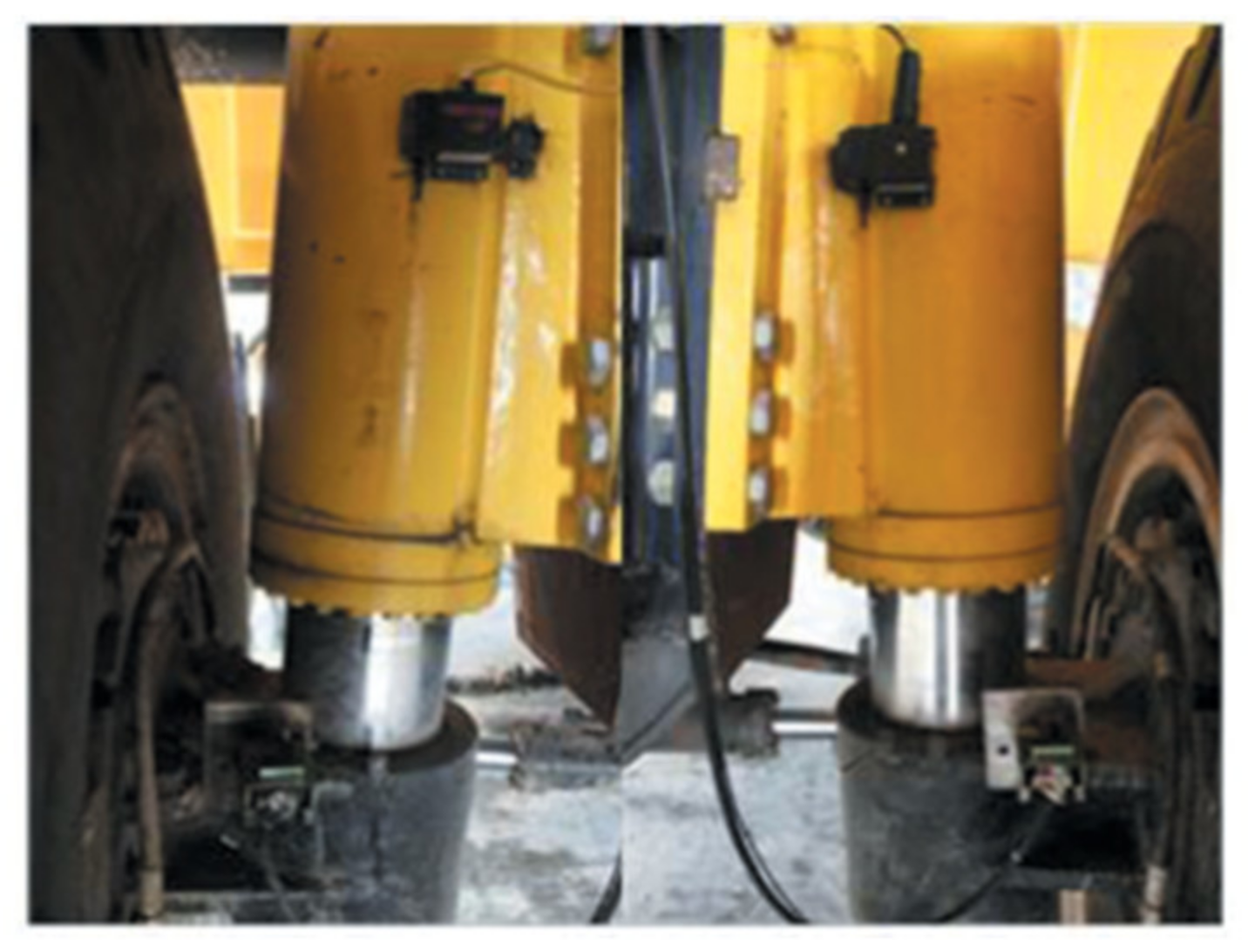
2. Hydro-Pneumatic Suspension Structure and Working Principle

The single-chamber hydro-pneumatic suspension is mainly composed of a cylinder barrel, a piston rod and a piston assembly. The gas chamber (accumulator) is placed in the inner cavity of the piston rod. The entire suspension cylinder forms a working cavity and an annular cavity, the piston rod wall is provided with damping holes and check valves. Figure 1 is a simplified physical model of the hydro-pneumatic suspension based on the above principles. When the piston rod moves upward and is in the compression stroke, the volume of nitrogen in the working chamber decreases and the pressure increases. The check valve and orifice connect the working chamber and the annular chamber at the same time, resulting in a relatively small oil damping force, the elastic effect of the gas in the accumulator is mainly used to restrain the upward movement of the piston rod. When the piston rod moves downward and is in the extension stroke, the one-way valve is closed and the damping force generated is relatively large, which has the strong effect of attenuating vibration. The general vehicle hydro-pneumatic suspension installation method is shown in Figure 2. The combination of the hydro-pneumatic spring suspension and tires, has the function of attenuating vibration and buffering shock.
After the above analysis and experiments, it was found that the dissolution rate of gas in the oil varies with temperature and pressure. The viscosity of the oil and the flow of the oil in the cylinder of the oil-air suspension all affect the characteristics of the oil-air suspension. The calculation accuracy of the hydro-pneumatic suspension damping characteristics equivalent to the pure viscous body needs to be improved. The characteristics of the hydro-pneumatic suspension are not only related to the magnitude of the external force, but also related to changes in temperature, time of force action and loading history, which are very consistent with the characteristics of viscoelastic materials.
The mechanical properties of viscoelastic materials are between ideal elastomers and Newtonian fluids. They not only exhibit elasticity, but also have viscous characteristics. Its stress-strain response depends on time and strain rate, and is also related to load and deformation history, that is, the stress-strain changes have memory. The fractional viscoelastic calculus model can accurately describe the dynamic characteristics of a large number of complex viscoelastic materials in a wide frequency range with fewer parameters [11] and can more accurately describe the dynamic characteristics of viscoelastic materials.
Based on the above ideas, this study equates the entire hydro-pneumatic suspension system as a viscoelastic system for research, and a fractional-order model is introduced to describe the damping loss term to analyze the basic hydro-pneumatic suspension system.

3. Establishment of Fractional Model of Hydro-Pneumatic Suspension

3.1. Definition of Fractional Derivative

There are many definitions of fractional calculus, and the most adopted one is the Riemann–Liouville (R–L) fractional calculus, which is defined as [12]:
a D t q f t = 1 Γ n q d n d x n a t t ξ n q 1 f ξ d ξ
where
  • D is the differential operator, the upper right corner q represents the order, the lower left corner a indicates the lower limit of the integral, and the lower right corner t indicates the upper limit of the integral.
  • Γ (nq) is the gamma function, n is any integer.
  • q is the fractional order, ξ is the integral variable.
In addition, the Caputo definition is more commonly used in engineering, which is defined as:
D t q a C f t = 1 Γ n q a t t ξ n q 1 f n ξ d ξ
The definition of fractional calculus and the definition of Caputo fractional calculus are both the definition of the function f(x) in the time domain. The Laplace transform of the R–L fractional derivative involves the initial value of the fractional integral and the initial value of the R–L fractional calculus. Although the solution containing the R–L fractional derivative can be obtained, it is difficult to provide reasonable physical meaning to these solutions. The biggest advantage of the definition of Caputo fractional calculus is that its initial value is the same as that of integer-order calculus, which has a clear physical meaning [13].

3.2. Fractional Model of Hydro-Pneumatic Suspension

Since there are many factors that affect the output characteristics of the suspension, it is necessary to make corresponding assumptions based on the specific conditions before establishing the mathematical model and simulating the characteristics of the hydro-pneumatic suspension. This study mainly studies the performance of the equivalent fractional viscoelasticity of the damping force of the hydro-pneumatic suspension. With the help of the research experience of the cylindrical hydraulic shock absorber [14], the working parameters are appropriately simplified and neglected when the characteristics of the hydro-pneumatic suspension are studied, and make the following assumptions: no leakage occurs between the piston, piston rod and cylinder; the elastic deformation of the rigid components of the system caused by the pressure change is not considered; the influence of the gravitational potential energy of the working fluid is not considered; the same instantaneous pressure is equal everywhere in the enclosed area under study.
The hydro-pneumatic spring is mainly composed of a cylinder barrel, a piston rod and a piston assembly. The piston rod wall is provided with a one-way valve and a damping hole. The entire suspension cylinder has a working cavity and an annular cavity. When the hydro-pneumatic suspension is externally excited, the piston rod and the piston assembly and the cylinder barrel have relative movement. Starting from the output force, its vibration characteristics were analyzed as a whole. Under external excitation, relative movement between the piston rod, the piston assembly and the cylinder barrel are required. The output force is mainly composed of gas elastic force, oil damping force and friction between the piston and the cylinder barrel. The output force formula is:
F = F k + F c + F f
where
  • F is the output force of the hydro-pneumatic suspension.
  • F k is the gas elastic force, F c is the oil damping force.
  • F f is the friction between the piston and the cylinder.
For the calculation of elastic force, damping force and friction force, the basic integer-order common calculation method was used [14], the elastic force is:
F k = p A 3 = M g V 0 γ v 0 A 3 x γ
where
  • p is the gas pressure in the working chamber.
  • γ is the gas multivariable index, the thermodynamic process can be regarded as an adiabatic process during rapid loading, taking 1.4.
  • A3 is the piston rod area, Mis the fluid density.
  • V0 is the gas volume at a static equilibrium position.
  • x is the relative displacement of piston and cylinder.
For the damping force of the hydro-pneumatic suspension, a thin-walled orifice type damping flow calculation method was selected [15], as:
F c = A 1 A 3 3 x ˙ 2 r s i g n x ˙ 2 n [ C z A z + C d A d 0.5 + 0.5 s i g n x ˙ ] 2
where
  • Cz, Az is the flow coefficient and flow area of the orifice.
  • Cd, Ad is the flow coefficient and flow area of the one-way valve.
  • Ρ is the oil density.
  • s i g n x ˙ is the sign function, which takes positive and negative values according to the speed direction of the input signal. The compression stroke is 1, and the extension stroke is −1. In order to facilitate calculation and description, only compression was considered.
For the calculation of the friction force of the hydro-pneumatic suspension, the calculation of the friction resistance of the seals of the hydraulic cylinder and the piston rod were used to calculate as follows:
F f = 2 μ π Δ p D b D k D + d b d k d
where
  • μ is the friction factor of the seal ring.
  • Δp is the pressure difference on both sides of the hydraulic cylinder sealing ring.
  • D is the inner diameter of hydraulic cylinder.
  • d is the outer diameter of piston rod.
  • bD, bd are the piston, and piston rod seal ring width.
  • kD, kd is the friction correction coefficient of the sealing ring.
The suspension model is shown in Figure 1. According to Equations (4)–(6), the integer-order equations of the suspension output force were obtained, and the dimensionless processing was performed at the same time, to make a 1 = A 1 A 3 3 r / [ 2 n 2 C z A z + C d A d 2 ] , a 2 = M g V 0 γ , a 3 = V 0 , a 4 = A 3 , then:
F = a x ˙ 2 + a 2 a 3 a 4 x 1.4 + F f
According to Figure 1, there are basic geometric relations:
x t = y t z t
x ¨ t = y t z ¨ t
where
  • z(t) is the output displacement at the upper end of the suspension.
  • y(t) is the input excitation displacement under the suspension.
In this study, a sinusoidal displacement excitation y(t) = Asin(ωt) was applied under the hydro-pneumatic suspension as input, that is, A is the excitation amplitude and ω is the excitation frequency.
According to the known integer-order equations, the simultaneous Equations (3)–(9), introduced fractional parameters for the dissipation damping term, and considered its own gravity to establish an equivalent fractional-order Bagley–Torvik damped vibration equation system [16]. After sorting, the nonlinear fractional-order equation of the output force of the hydro-pneumatic suspension was found.
m x ¨ = a 1 D q x 2 + a 2 a 3 a 4 1.4 + F f + m g m ω 2 A sin w t
Equation (10) is a fractional nonlinear ordinary differential equation. The variable x in the elastic force term is located on the denominator, which is a nonlinear term, and the damping force term is squared, which causes the vibration output force of the suspension to be nonlinear. It is impossible to find analytical solutions for most fractional differential equations, and the analytical solutions of such fractional differential equations can only be represented by special functions. Generally, numerical solutions of such equations are obtained.
For unknown signals, designing a continuous filter based on the Oustaloup algorithm [17] to achieve fractional calculus on the signal is a common method to solve its numerical solution. The Oustaloup algorithm uses Taylor expansion and first-order approximation to obtain the transfer function in the frequency range. At the same time, considering that the numerator and denominator of the filter have the same order, it may lead to a modern number loop in the simulation process, and then a low-pass filter is connected behind. In this way, the zero-pole and gain functions of the filter can be programmed, and the fractional differentiator module shown in Figure 3 can be established in Simulink. Furthermore, the entire differential equation can be constructed and its numerical solution can be obtained.

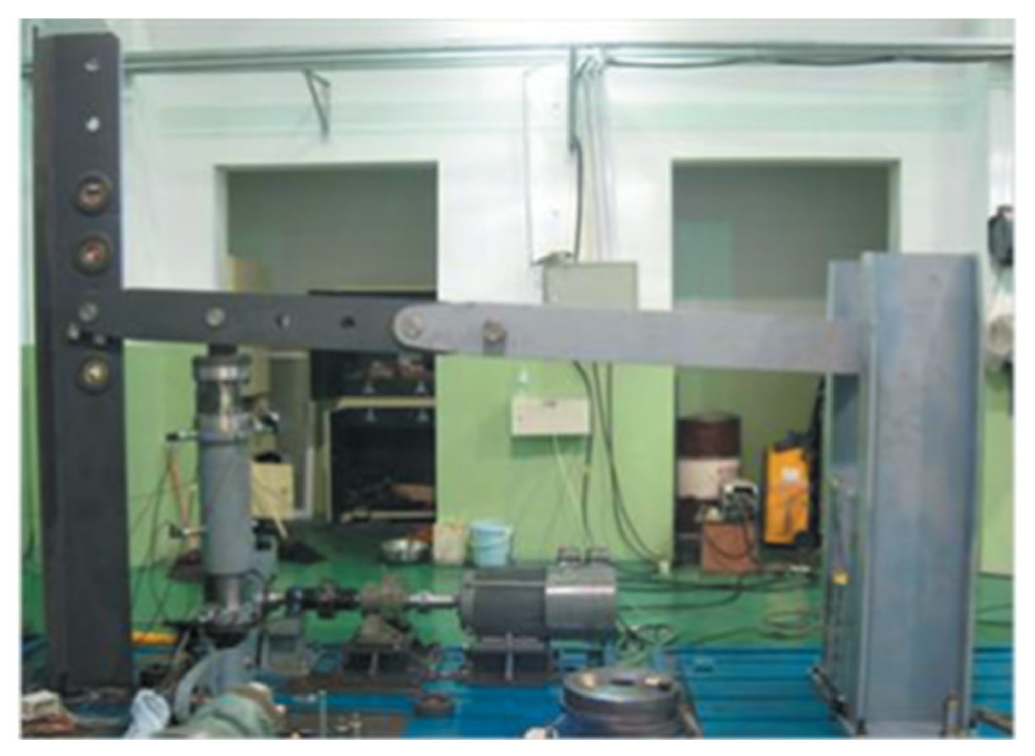
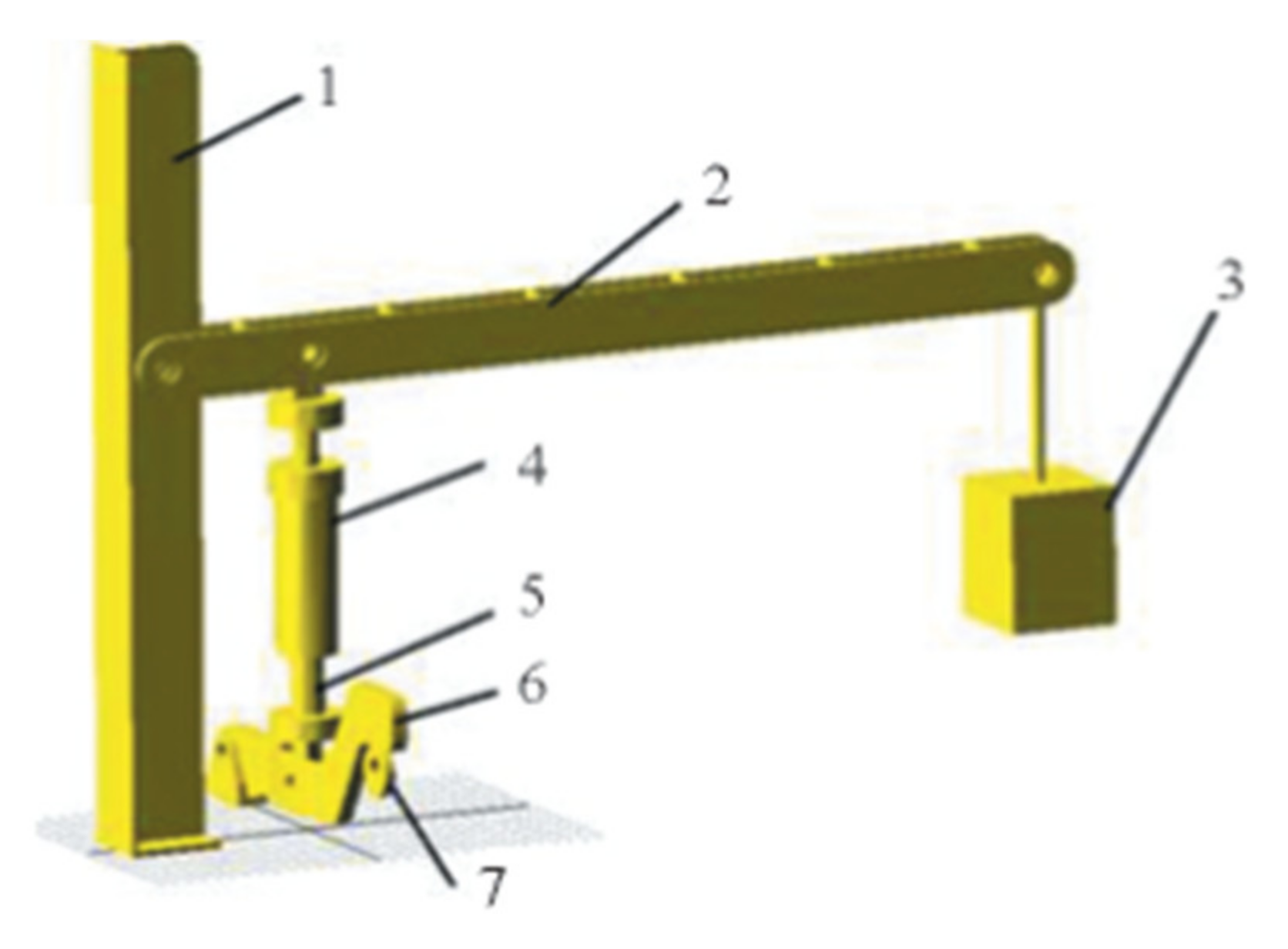
4. Numerical Solution and Test of the Fractional Characteristics of Suspension

The self-designed isometric test bench is shown in Figure 4, referring to the vibration model of a 1/4 vehicle to simulate the working state of the hydro-pneumatic suspension during the actual operation of the vehicle. A number of sensors such as displacement, acceleration, tension and pressure were installed to test the output characteristics of the hydro-pneumatic suspension when subjected to external excitation and load.
The power of the whole bench was sent by the three-phase asynchronous motor with frequency conversion and speed regulation at the lower end, which then acted on the eccentric wheel contacting the bracket after passing through the reducer. The eccentric wheel was kept in contact with the transmission beam, and the transmission beam was hinged with the piston rod of the suspension cylinder through the joint bearing, and the hinge point was located in the middle part of the transmission beam. When the eccentric wheel rotates with the motor at a uniform speed, it drives the transmission beam to swing up and down, and the swing transmission to the hinged joint between the piston rod of the suspension cylinder and the transmission beam is a vertical sinusoidal excitation. The advantages of this design are: the load of the motor can be effectively reduced by the transmission beam; the frequency of excitation can be changed at any time by adjusting the frequency of the motor; the amplitude of the excitation can be changed by adjusting the eccentricity of the eccentric; the load on the suspension sprung can be changed the number of mass blocks to adjust its size.
In order to verify the accuracy of the fractional-order theory and compare with the integer-order, and fully describe the test process and results, this study established a three-dimensional model of the entire bench based on the structure design of the test bench as shown in Figure 5. The model was imported into ADAMS/View, and each of the material properties of the components were set, component constraints and force relations were added. It was combined with the LMS Amesim hydraulic software to obtain the multi-rigid integer-order simulation model and the results of the test bench and compare them with the established fractional-order model.
The basic parameters of the suspension cylinder used in the test: cylinder inner diameter 155 mm, piston rod outer diameter 105 mm, orifice diameter 6 mm, check valve equivalent diameter 5.6 mm, and stroke 260 mm. The research mainly compares the output characteristics of the suspension cylinder under the same working conditions, that is, the vibration acceleration of the sprung load, the amplitude and frequency of the output force of the suspension cylinder, and the dynamic stroke of the suspension cylinder.
This article focuses on the analysis of sinusoidal excitation when the eccentricity of the eccentric is 10 mm and the rotation frequency is 1 Hz, which is also a common frequency for construction vehicles. In this study, a trial-and-error method was selected, and multiple different fractional orders, such as 0.8, 0.9, 1.1, 1.2, etc. were compared and analyzed after the vibration steady state. It was found that the 0.9th order is the closest to the actual measurement result, the waveform and frequency were the most consistent, and the amplitude error range was very small. The following analysis is based on the 0.9th order fractional order result, the integer-order simulation result, and the comparison of the actual measured data.
Figure 6 shows the comparison of the relative displacement of the suspension cylinder. In the amplitude results, the 0.9th order is closer to the actual situation. The integer-order amplitude is larger than the experimental data, and the maximum amplitude exceeds the actual value by 2 mm. In principle, for the relationship between motion and the order of the damping term, as the order q increases, the vibration becomes more and more intense, and the greater the amplitude of the vibration displacement, the influence of the previous motion state on the next moment is weakened. On the contrary, the smaller it is, the more this correlation is, the larger the damping force and the smaller the amplitude. The measured data were measured after the suspension was vibrating stably, and the phase was different from the simulation data, but it is obvious that the fractional modeling is more accurate in terms of amplitude, especially at the bottom dead center position of the displacement.
Figure 7 shows the acceleration curve of the suspension cylinder. Similar frequency and amplitude are very close to those in Figure 6. The curve of the apparent simulation result is smoother than the test result. This is because the construction of the test bench is treated as a rigid body in the simulation model, the high-frequency vibration of the transmission beam and other components is not considered, and the overall difference has little effect on the results.
Figure 8 shows the output force curve of the suspension cylinder. When the model reaches dynamic balance, the output force of the hydro-pneumatic suspension changes periodically, and the amplitude change frequency is similar to the test result. The highly coupled and complex working conditions of the hydro-pneumatic suspension itself make viscoelastic characteristics appear and tend to be stable. The advantage of the fractional model in the compression stroke is not obvious, and the fractional results in the extension stroke are much closer to the measured data than the integer order. This is because the elastic force plays a major role in the compression stroke, while the damping force plays a major role in the extension stroke. The introduction of the fractional-order model is to adjust the damping force, and its advantage is obvious in the extension stroke. The adjustment of the damping force also causes the output force to be delayed compared with the integer order, and the maximum output force appears later.
Figure 9 is the cylinder displacement-output force curve, and Figure 10 is the cylinder speed-output force curve. It is found by comparison that the piston compression and extension strokes are a non-coincident process due to the damping force. Especially in the extension stroke, the extension stroke is made smaller under the action of damping. The introduction of the fractional order emphasizes this point. The results of the fractional-order model have more obvious advantages in the second half of extension and the first half of compression. The time of the minimum value and maximum value is closer to the actual measurement result, and the change trend is more consistent.

5. Conclusions

(1)
According to the working principle of the hydro-pneumatic suspension, highlighting the characteristics of the multi-phase medium of the hydro-pneumatic suspension, using the equivalent viscoelastic damping analysis method, introducing the fractional derivative to describe, and establish the Bagley–Torvik equation of the hydro-pneumatic suspension;
(2)
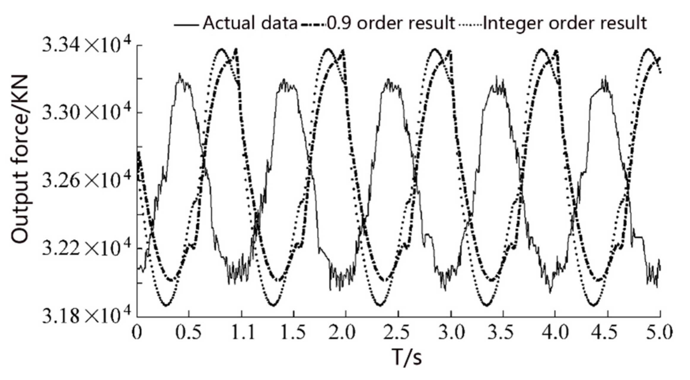
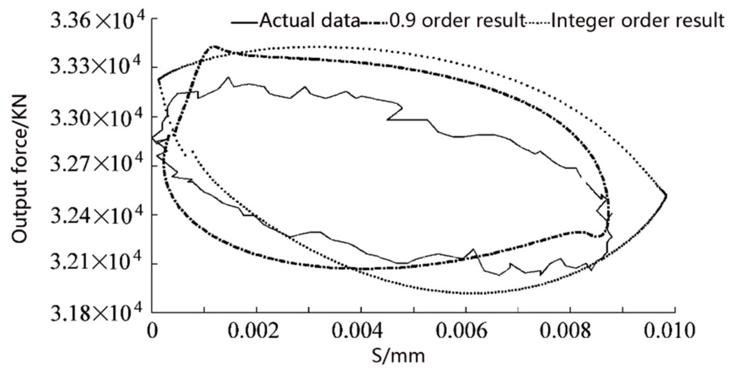
According to the definition of the fractional-order model, the Oustaloup algorithm is used to numerically solve the fractional-order nonlinear differential equation, and the mechanical properties are described from the constitutive equation, and multiple numerical results such as the fractional output force, displacement, and velocity of the hydro-pneumatic suspension are obtained;
(3)
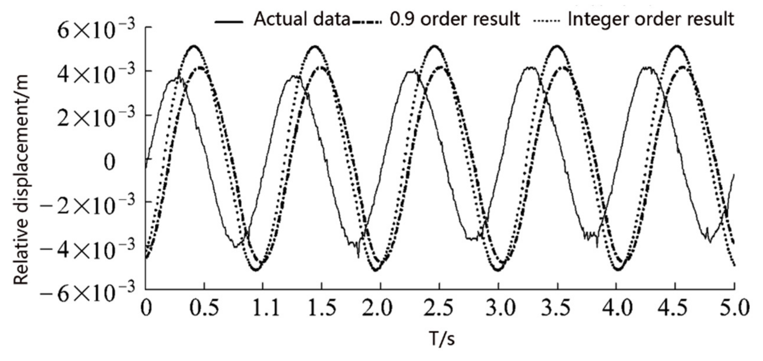
The fractional-order and integer-order simulation and test results are compared to verify the correctness of the fractional-order model. The results show that the fractional order of 0.9 is the closest to the test results. This concise model can describe the characteristics of the hydro-pneumatic suspension more accurately, which is of great significance to the improvement of design and precise control.

Author Contributions

Conceptualization, H.S.; methodology, J.X.; software, B.Z.; validation, R.L.; resources, X.D.; data curation, F.X.; writing—original draft preparation, H.S.; writing—review and editing, R.L.; visualization, B.Z.; supervision, R.L.; project administration, R.L.; funding acquisition, R.L. All authors have read and agreed to the published version of the manuscript.

Funding

This research was funded by 2020 Shandong Province Key Research and Development Program (Major Technological Innovation Project), Large Tractor Hydraulic CVT Intelligent Continuously Variable Transmission Integration Research and Application (2020CXGC010806), and 2020 Shandong Province Key Research and Development Program (Major Technological Innova-tion Project), Con-struction Machinery Integration Research and Application of Key Technologies for Intelligent Integration and Matching of Vehicle Assembly (2020CXGC011005), and 2020 Jinan City Science and Technology Bureau University Institute Innovation Team Project, Research on Key Technologies of Intelligent Electro-hydraulic Control System for Large Power Platform.

Institutional Review Board Statement

Not applicable.

Informed Consent Statement

Not applicable.

Data Availability Statement

The data presented in this study are available on request from the corresponding author.

Conflicts of Interest

The authors declare no conflict of interest.

References

  1. Ieluzzi, M.; Turco, P.; Montiglio, M. Development of a heavy truck semi-active suspension control. Control Eng. Pract. 2006, 14, 305–312. [Google Scholar] [CrossRef]
  2. Gao, B.; Darling, J.; Tilley, D.G.; Williams, R.A.; Bean, A.; Donahue, J. Control of a hydro pneumatic active suspension based on a non-linear quarter-car model. J. Syst. Control Eng. 2006, 220, 15–31. [Google Scholar]
  3. Sun, T.; Yu, F.; Zhang, Z. Uncertainty analysis for a hydro-pneumatic suspension system of heavy duty vehicles and H∞ controller design. J. Vib. Shock 2007, 26, 51–54. (In Chinese) [Google Scholar]
  4. Wang, H.; Zhang, P.; Shao, Z. The viberation Characteristics of the Heavy Vehicle with Composite Interconnecting Oi-Air Suspension. Missles Space Vehic. 2003, 4, 7–11. [Google Scholar]
  5. Tian, J.; Di, Y.; Xiang, H. Study on rigid property and damping capacity of HPS with isolated single-chamber. Trans. Chin. Soc. Agric. Mach. 2007, 38, 35–38. (In Chinese) [Google Scholar]
  6. Yang, J.; Chen, S.; Wu, Z. Design and testing on the hydro-pneumatic suspensions with controllable stiffness and damping. Trans. Chin. Soc. Agric. Mach. 2008, 39, 20–24. (In Chinese) [Google Scholar]
  7. Ma, G.; Tan, R.; Wu, R. Non-linear mathematic model of hydro-pneumatic suspension crane vehicles and its simulation. Chin. J. Mech. Eng. 2002, 38, 95–98. (In Chinese) [Google Scholar] [CrossRef]
  8. Li, Z.; Tong, J.; Wei, L. Optimal design of asingle chamber hydro-pneumatic spring. J. Vib. Shock 2011, 30, 166–171. (In Chinese) [Google Scholar]
  9. Longxin, Z.; Wenming, Z. Research on simulation and experiment of hydro-pneumatic suspension with single gas cell. Chin. J. Mech. Eng. 2009, 45, 290–294. (In Chinese) [Google Scholar]
  10. Hang, X.; Yang, J.; Shen, Y.; Feng, Y. Characteristics Analysis of Hydro Pneumatic suspension based on gas dissolution and oil compressibility. Transact. Chin. Soc. Agric. Mach. 2013, 44, 14–18. (In Chinese) [Google Scholar]
  11. Adolfsson, K.; Enelund, M.; Olsson, P. On the Fractional Order Model of Viscoelasticity. Mech. Time-Depend. Mater. 2005, 9, 15–34. [Google Scholar] [CrossRef]
  12. Friedrich, C. Relaxation and retardation functions of the Maxwell model with fractional derivatives. Rheol. Acta 1991, 30, 151–158. [Google Scholar] [CrossRef]
  13. Song, D.Y.; Jiang, T. Study on the constitutive equation with fractional derivative for viscoelastic fluids-modified Jeffreys models and its application. Rheol. Acta 1998, 37, 512–517. [Google Scholar] [CrossRef]
  14. Yong, C.; Zhonghao, H. Study and review on the resistance specificity of automobile hydraulic damper. J. Liaoning Inst. Technol. 2001, 21, 8–11. (In Chinese) [Google Scholar]
  15. Lei, T. The Second Volume of The New Hydraulic Engineering Manual; Beijing Institute of Technology Press: Beijing, China, 1998; Volume 12, p. 1389. [Google Scholar]
  16. Shujun, S.; Fawang, L. A computational efficient numerical method of solving fractional Bagley-Torvik equation. J. Xiamen Univ. Nat. Sci. 2004, 3, 306–311. [Google Scholar]
  17. Xue, D. MATLAB Solution to Higher Applied Mathematics Problems; Tsinghua University Press: Beijing, China, 2008; pp. 398–399. [Google Scholar]
Figure 1. Schematic diagram of single-chamber hydro-pneumatic suspension. 1. Working cavity 2. Annular cavity 3. Damping hole 4. Check valve.
Processes 09 01414 g001
Figure 2. Suspension test of real vehicle.
Processes 09 01414 g002
Figure 3. Fractional differential filter.
Processes 09 01414 g003
Figure 4. Test stand of hydro-pneumatic suspension.
Processes 09 01414 g004
Figure 5. Software simulation of test stand. 1. Support 2. Beam 3. Mass 4. Cylinder 5. Piston rod 6. Transmission beam 7. Cam.
Processes 09 01414 g005
Figure 6. Data of displacement curves comparison diagram.
Processes 09 01414 g006
Figure 7. Accelerated speed of cylinders comparison.
Processes 09 01414 g007
Figure 8. Output force of suspension cylinders comparison.
Processes 09 01414 g008
Figure 9. Displacement—output force of cylinder comparison.
Processes 09 01414 g009
Figure 10. Speed—output force of cylinder comparison.
Processes 09 01414 g010
Publisher’s Note: MDPI stays neutral with regard to jurisdictional claims in published maps and institutional affiliations.

