
Interactive Effects in Two-Droplets Combustion of RP-3 Kerosene under Sub-Atmospheric Pressure


Abstract
:1. Introduction
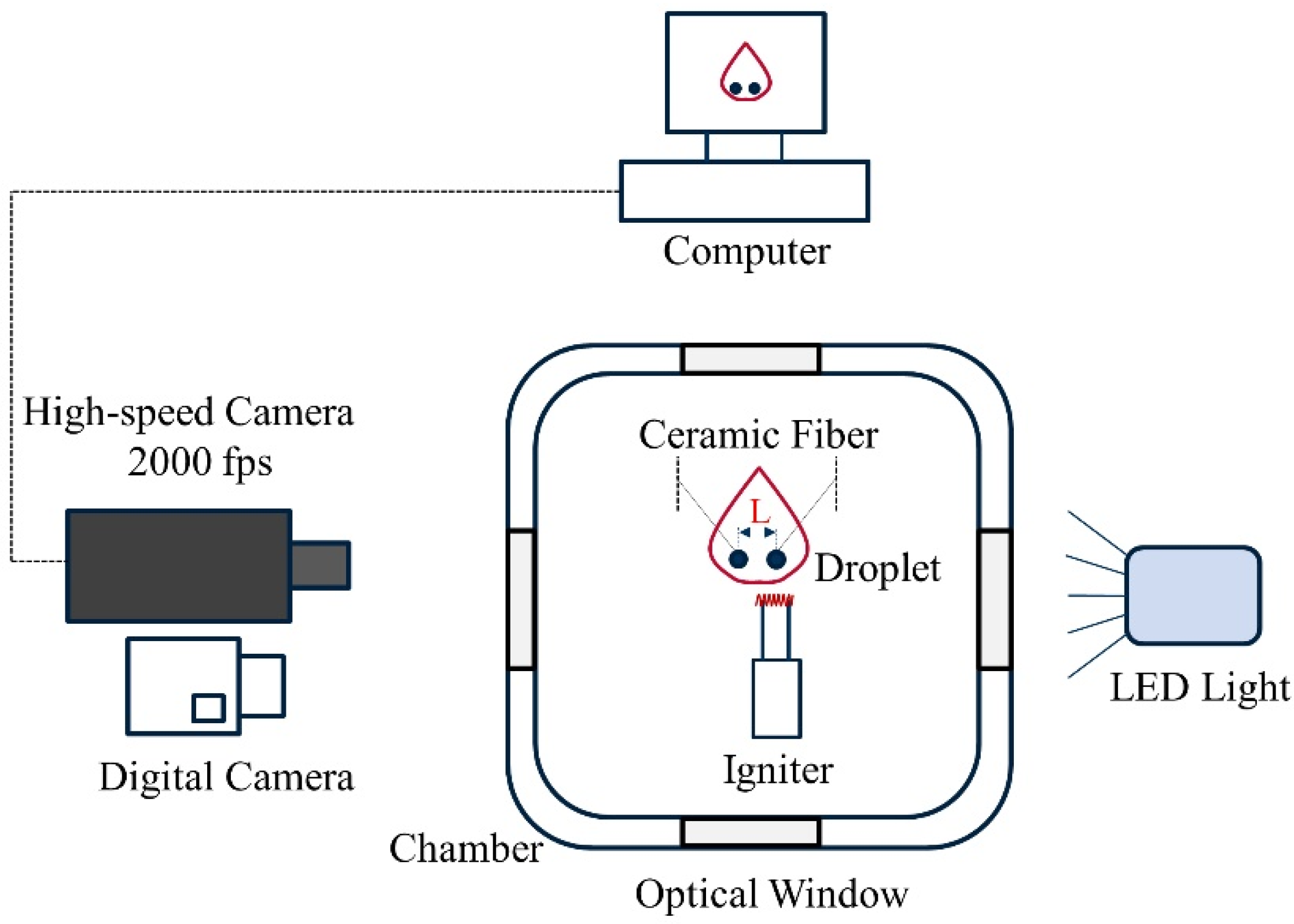
2. Materials and Methods
3. Results and Discussion
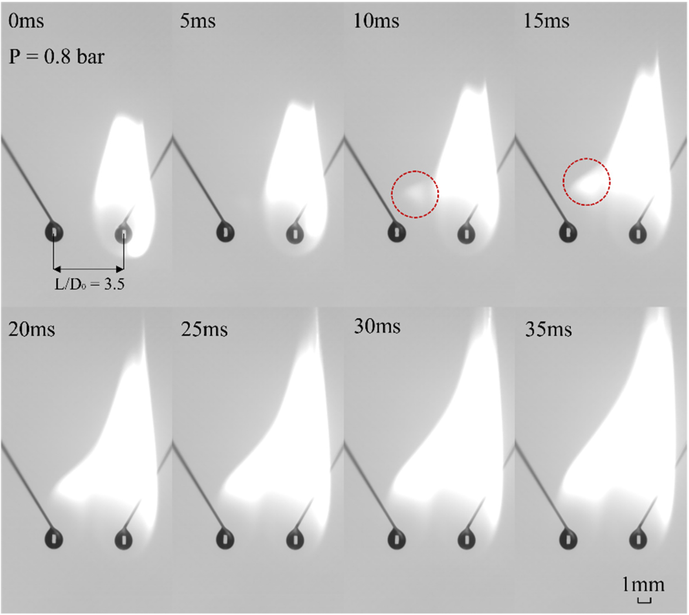
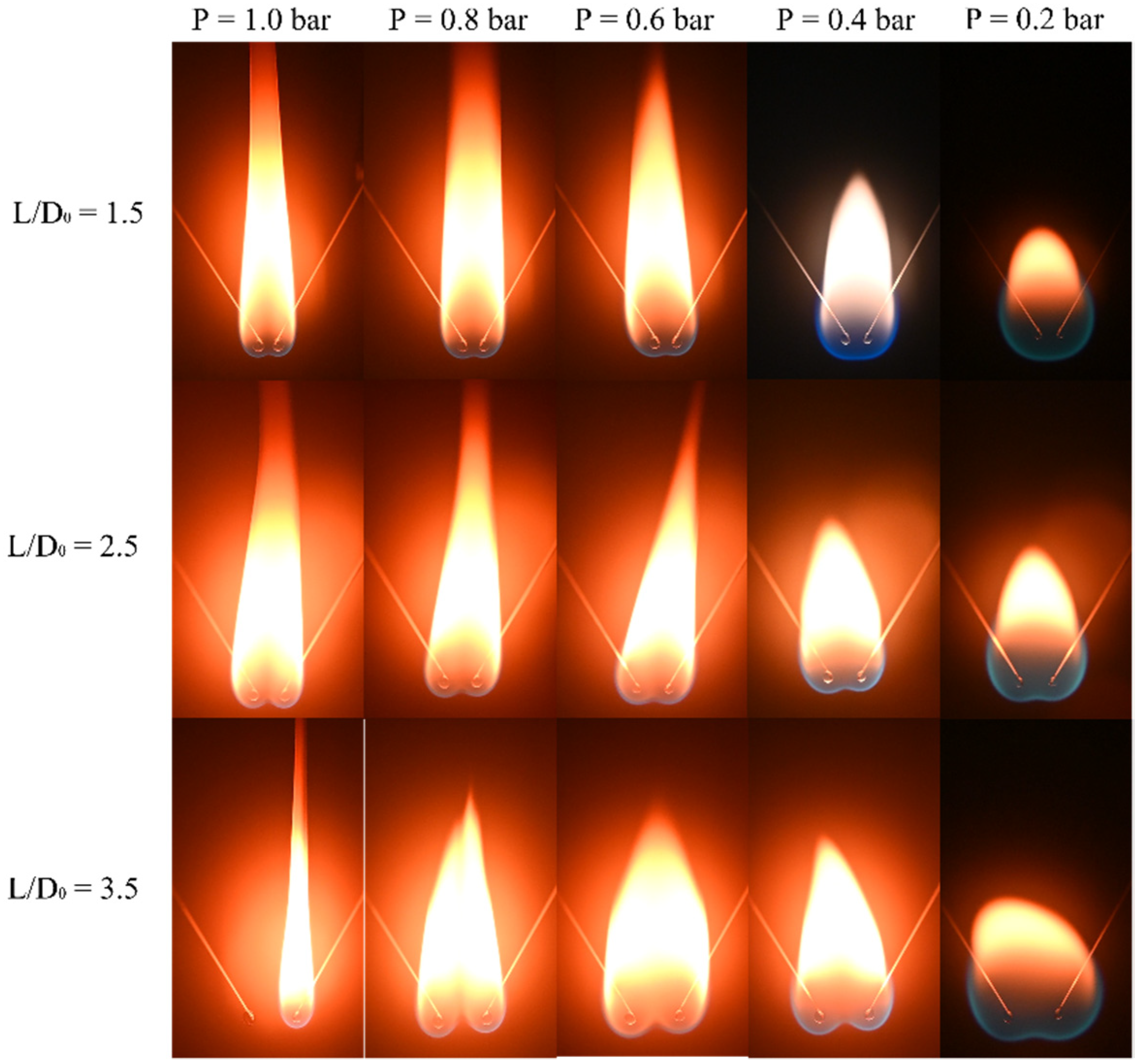
3.1. Ignition and Flame Shape
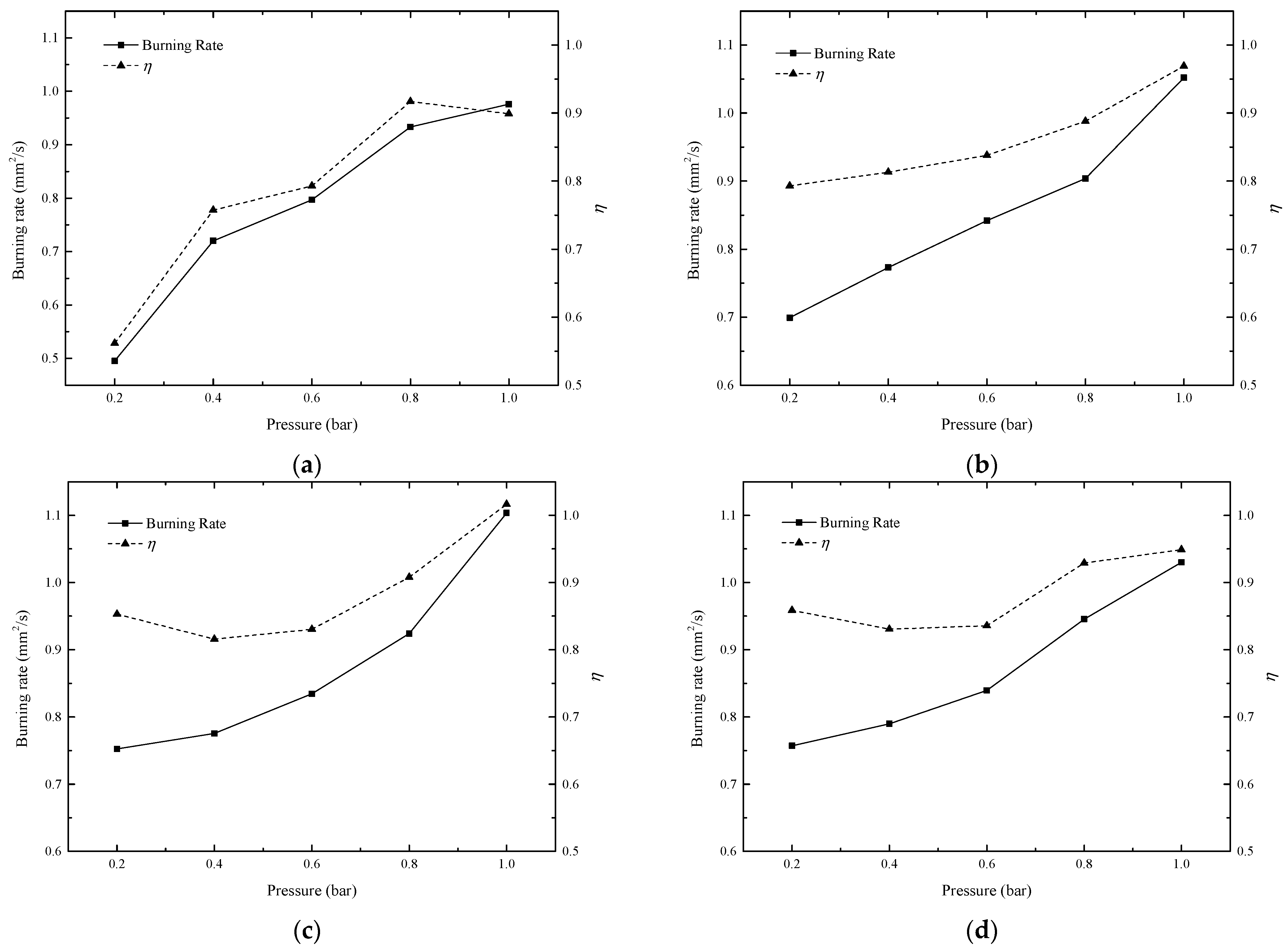
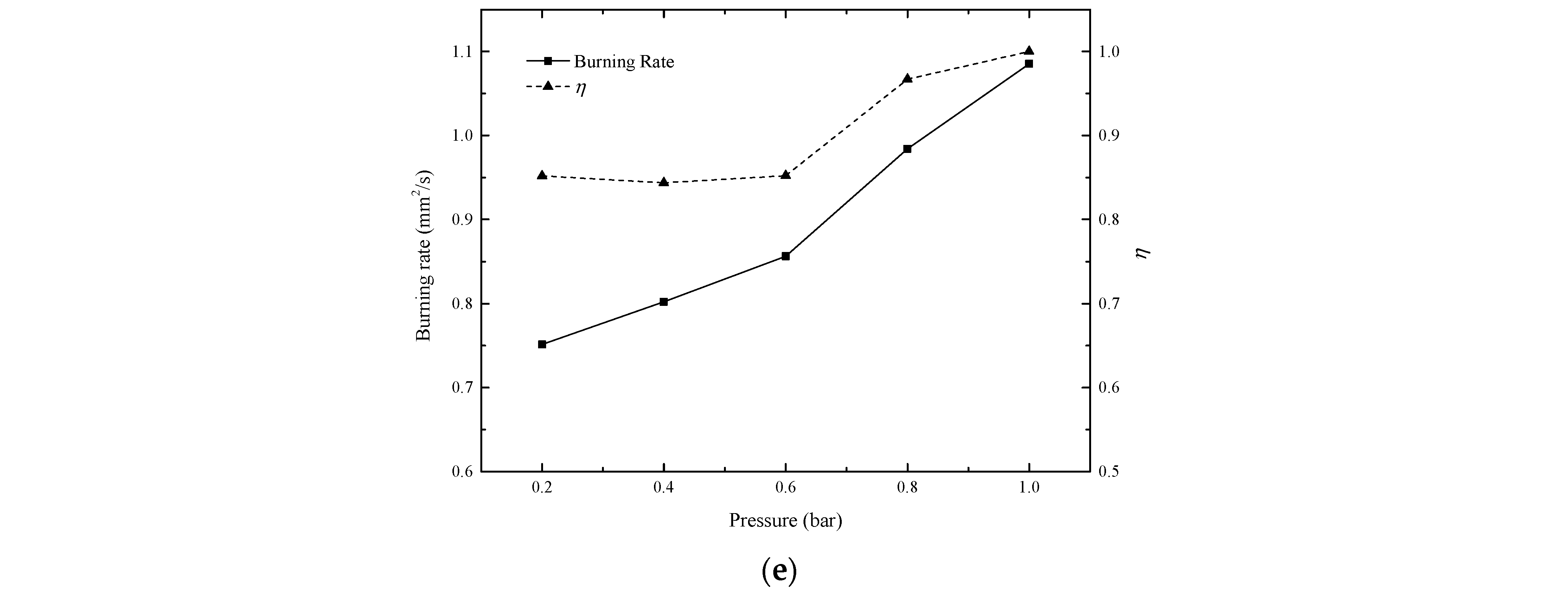
3.2. Burning Rate
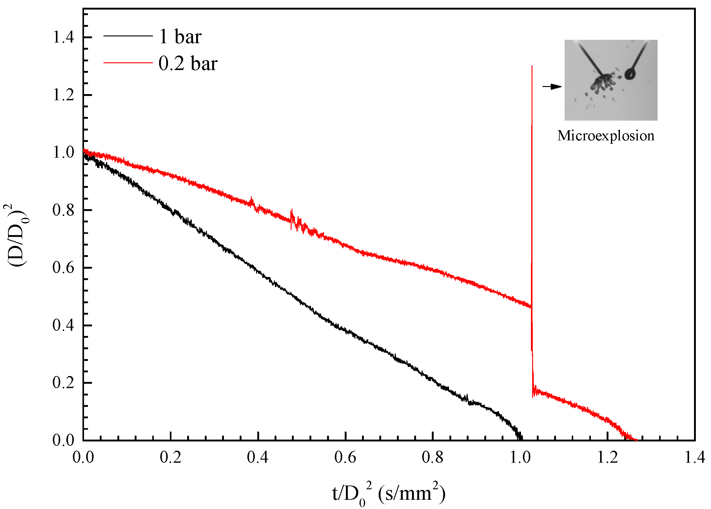
3.3. Effects of Puffing and Microexplosion
4. Conclusions
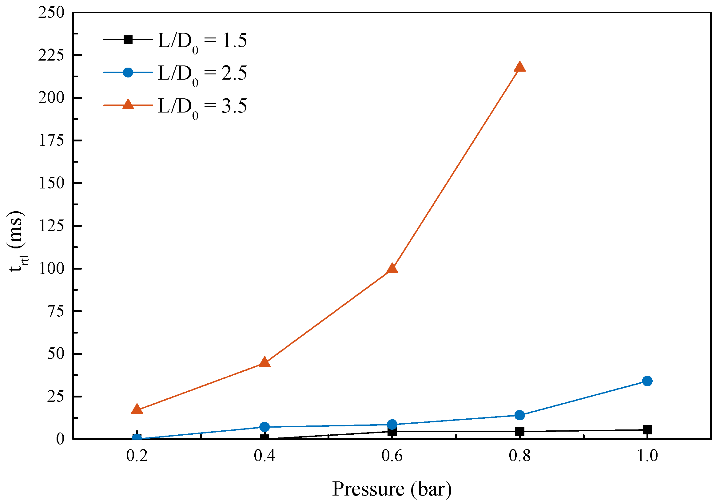
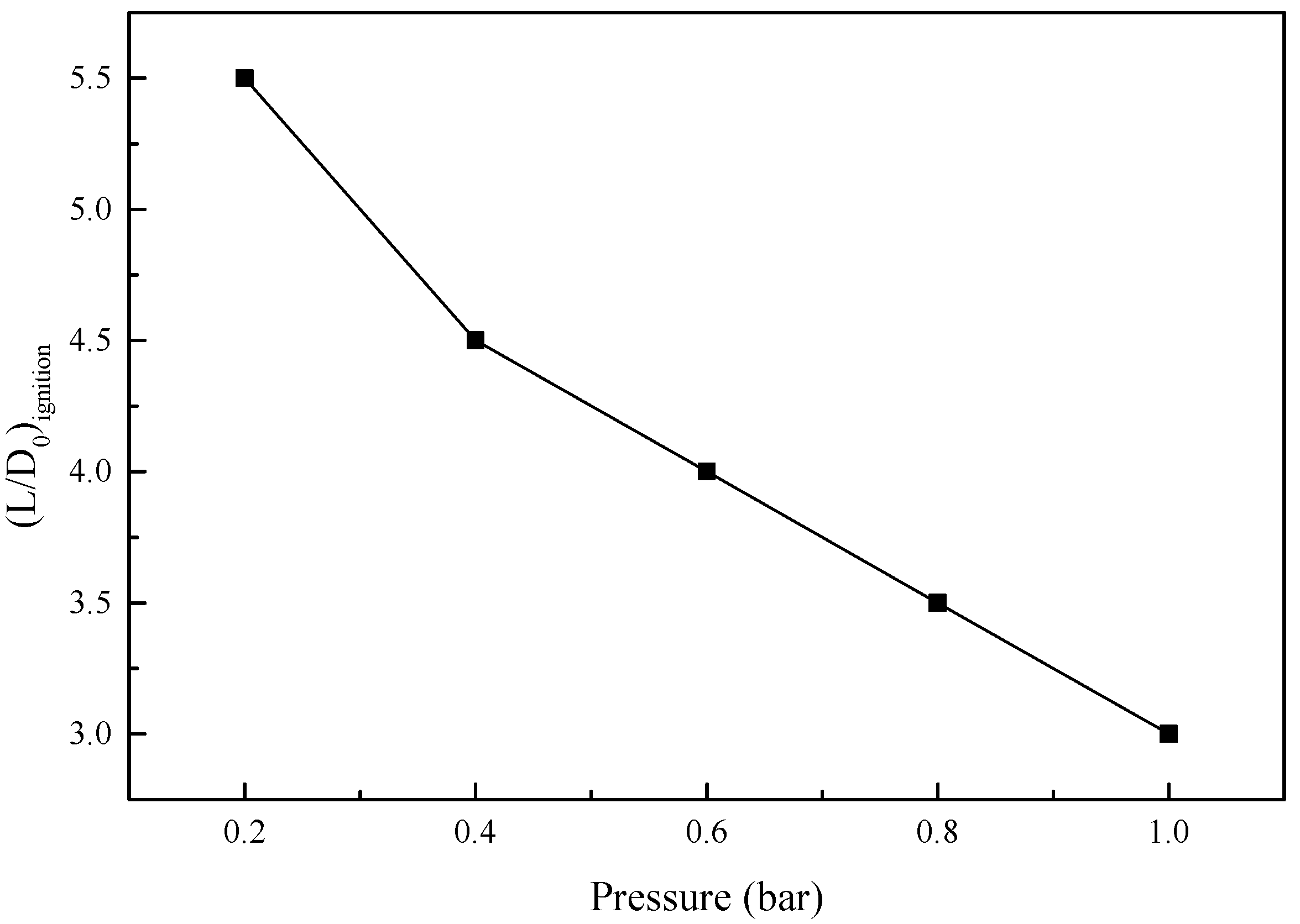
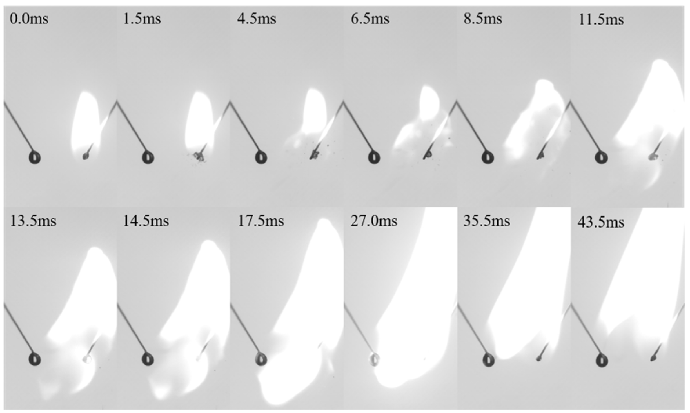
- In a stabilised two-droplets system, the flame propagation time from the right burning droplet to the left droplet elongated exponentially with the increase of the ambient pressure and normalised spacing distance. The maximum normalised spacing distance at which the left droplet could be ignited was extended from 3.0 to 5.5 for an ambient pressure decrease from 1 bar to 0.2 bar, respectively.
- Much like the burning of the single droplet, the reduction in ambient pressure enhanced the possibility and intensity of puffing and microexplosion during the burning. In general, compared to the corresponding isolated RP-3 kerosene droplet, the burning rate of the interacting droplets was reduced, owing to the oxygen competition between the droplets. However, the interactive coefficient η exceeded one when L/D0 = 2.5 and P = 1 bar. This is attributed to the increase in heat transferred from the sooty flame.
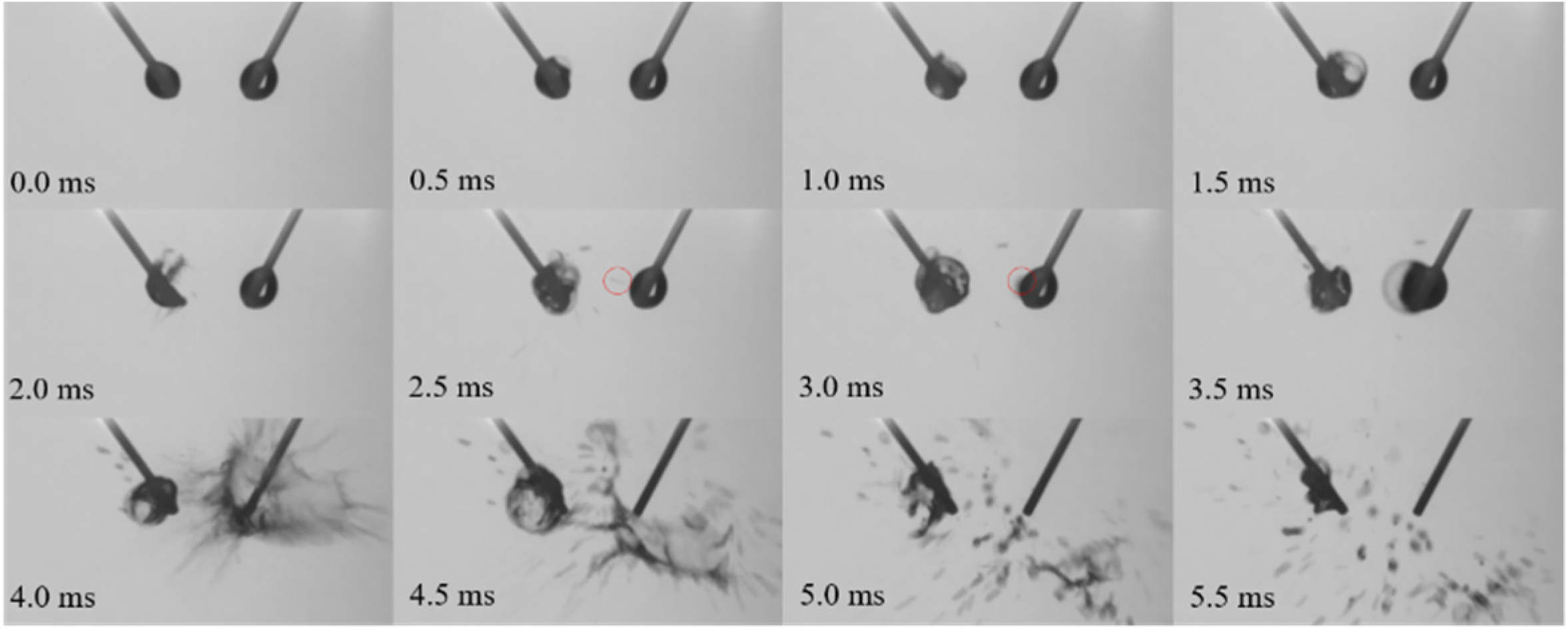
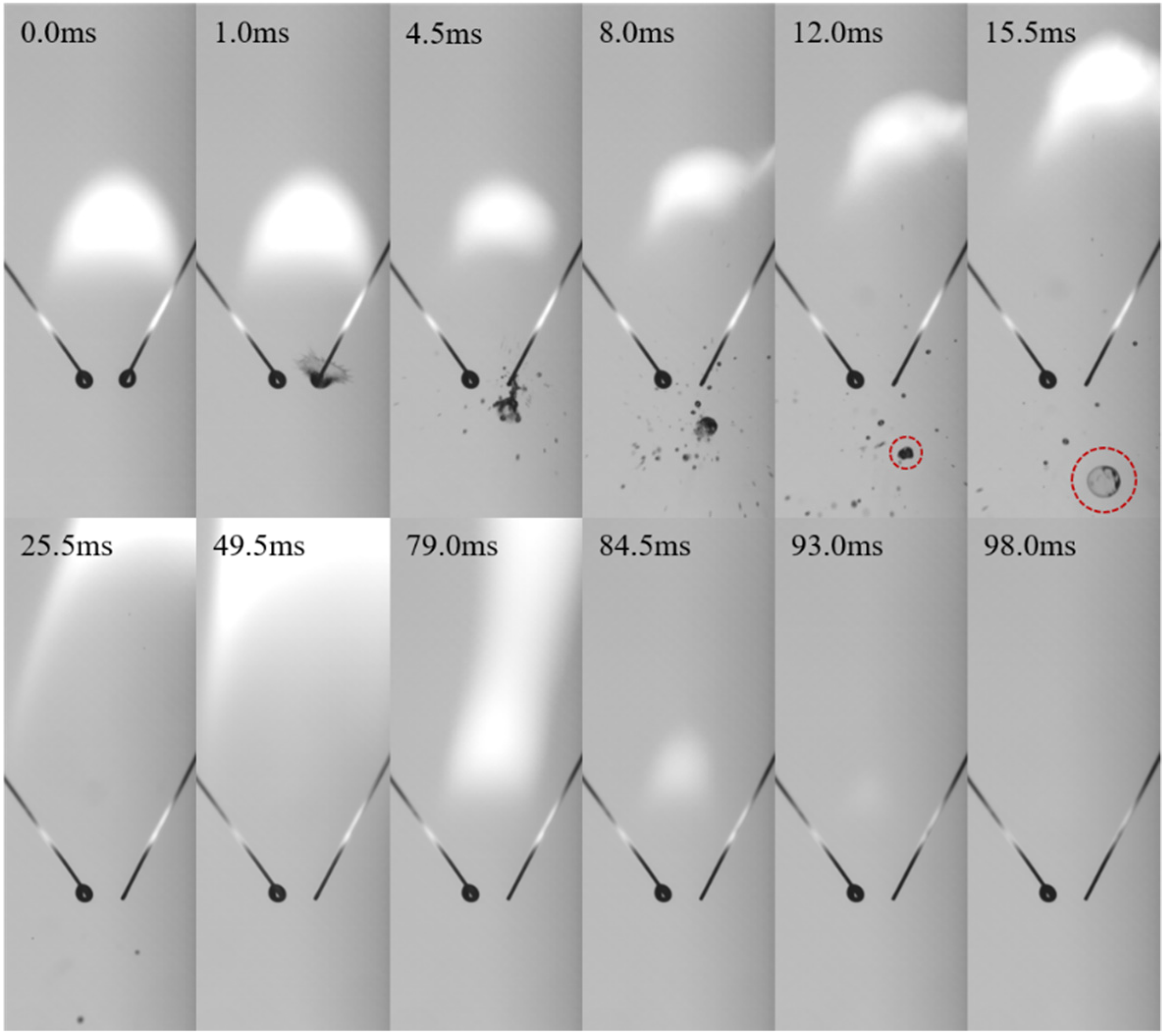
- During the burning of binary droplets, the secondary atomization could be affected by puffing and microexplosion from its neighbouring droplet. Puffing and microexplosion of the right droplet can also extend the limit of the maximum normalised spacing distance at which the left droplet can be ignited. Meanwhile, the extinction of the two-droplets’ burning was caused by the severe microexplosion that occurred when P = 0.2 bar.
Author Contributions
Funding
Institutional Review Board Statement
Informed Consent Statement
Data Availability Statement
Conflicts of Interest
References
- Inamura, T.; Takahashi, M.; Kumakawa, A. Combustion Characteristics of a Liquid-Fueled Ramjet Combustor. J. Propuls. Power 2001, 17, 860–868. [Google Scholar] [CrossRef]
- Luo, W.L.; Pan, Y.; Tan, J.G.; Wang, Z.G. Experimental investigation on combustion efficiency of the ramjet model at low pressure. J. Propuls. Technol. 2010, 31, 270–275. [Google Scholar]
- Dagaut, P.; Cathonnet, M. The ignition, oxidation, and combustion of kerosene: A review of experimental and kinetic modeling. Prog. Energy Combust. Sci. 2006, 32, 48–92. [Google Scholar] [CrossRef]
- Law, C.K. Theory of thermal ignition in fuel droplet burning. Combust. Flame 1978, 31, 285–296. [Google Scholar] [CrossRef]
- Farouk, T.I.; Liu, Y.C.; Savas, A.J.; Avedisian, C.T.; Dryer, F.L. Sub-millimeter sized methyl butanoate droplet combustion: Microgravity experiments and detailed numerical modeling. Proc. Combust. Inst. 2013, 34, 1609–1616. [Google Scholar] [CrossRef]
- Ambekar, A.; Chowdhury, A.; Challa, S.; Radhakrishna, D. Droplet combustion studies of hydrocarbon-monopropellant blends. Fuel 2014, 115, 697–705. [Google Scholar] [CrossRef]
- Shinjo, J.; Xia, J.; Ganippa, L.C.; Megaritis, A. Physics of puffing and microexplosion of emulsion fuel droplets. Phys. Fluids 2014, 26, 103302. [Google Scholar] [CrossRef]
- Wang, C.-H.; Liu, X.Q.; Law, C.K. Combustion and microexplosion of freely falling multicomponent droplets. Combust. Flame 1984, 56, 175–197. [Google Scholar] [CrossRef]
- Mura, E.; Calabria, R.; Califano, V.; Massoli, P.; Bellettre, J. Emulsion droplet micro-explosion: Analysis of two experi-mental approaches. Exp. Therm. Fluid. Sci. 2014, 56, 69–74. [Google Scholar] [CrossRef]
- Avulapati, M.M.; Ganippa, L.C.; Xia, J.; Megaritis, A. Puffing and micro-explosion of diesel–biodiesel–ethanol blends. Fuel 2016, 166, 59–66. [Google Scholar] [CrossRef] [Green Version]
- Hoxie, A.; Schoo, R.; Braden, J. Microexplosive combustion behavior of blended soybean oil and butanol droplets. Fuel 2014, 120, 22–29. [Google Scholar] [CrossRef]
- Liu, Y.; Liu, Y.; Chen, D.; Fang, W.; Li, J.; Yan, Y. A Simplified Mechanistic Model of Three-Component Surrogate Fuels for RP-3 Aviation Kerosene. Energy Fuels 2018, 32, 9949–9960. [Google Scholar] [CrossRef]
- Mikami, M.; Kono, M.; Sato, J.I.; Dietrich, D.L. Interactive effects in two-droplet combustion of miscible binary fuels at high pressure. Symp. (Int.) Combust. 1998, 27, 2643–2649. [Google Scholar] [CrossRef]
- Sangiovanni, J.J.; Kesten, A.S. Effect of droplet interaction on ignition in monodispersed droplet streams. Symp. (Int.) Combust. 1977, 16, 577–592. [Google Scholar] [CrossRef]
- Annamalai, K.; Ryan, W. Interactive processes in gasification and combustion. Part I: Liquid drop arrays and clouds. Progr. Energy Combust. Sci. 1992, 18, 221–295. [Google Scholar] [CrossRef]
- Koshland, C.P.; Bowman, C.T. Combustion of monodisperse droplet clouds in a reactive environment. Symp. (Int.) Combust. 1985, 20, 1799–1807. [Google Scholar] [CrossRef]
- Oka, K.; Tsue, M.; Kono, M.; Mikami, M.; Sato, J.; Dietrich, D.L.; Williams, F.A. Strongly interacting combustion of two mis-cible binary-fuel droplets at high pressure in microgravity. Symp. (Int.) Combust. 1998, 27, 2651–2657. [Google Scholar] [CrossRef]
- Xiong, T.Y.; Law, C.K.; Miyasaka, K. Interactive vaporization and combustion of binary droplet systems. Symp. (Int.) Combust. 1985, 20, 1781–1787. [Google Scholar] [CrossRef]
- Faik, A.M.-D.; Zhang, Y. Liquid-phase dynamics during the two-droplet combustion of diesel-based fuel mixtures. Exp. Therm. Fluid. Sci. 2020, 115, 110084. [Google Scholar] [CrossRef]
- Yoshida, Y.; Iwai, K.; Nagata, K.; Seo, T.; Mikami, M.; Moriue, O.; Sakashita, T.; Kikuchi, M.; Suzuki, T.; Nokura, M. Flame-spread limit from interactive burning droplets in microgravity. Proc. Combust. Inst. 2019, 37, 3409–3416. [Google Scholar] [CrossRef]
- Nomura, H.; Iwasaki, H.; Suganuma, Y.; Mikami, M.; Kikuchi, M. Microgravity experiments of flame spreading along a fuel droplet array in fuel vapor-air mixture. Proc. Combust. Inst. 2011, 33, 2013–2020. [Google Scholar] [CrossRef]
- Shaw, B.D.; Dwyer, H.A.; Wei, J.B. Studies on Combustion of Single and Double Streams of Methanol and Metha-nol/Dodecanol Droplets. Combust. Sci. Technol. 2002, 174, 29–50. [Google Scholar] [CrossRef]
- Mikami, M.; Kato, H.; Sato, J.; Kono, M. Interactive combustion of two droplets in microgravity. Symp. (Int.) Combust. 1994, 25, 431–438. [Google Scholar] [CrossRef]
- Wei, J.B.; Shaw, B.D. Reduced Gravity Combustion of Propanol Droplets in Oxygen-Inert Environments. Combust. Sci. Technol. 2009, 181, 1480–1494. [Google Scholar] [CrossRef]
- Law, C.K.; Law, H.K. A d2-Law for Multicomponent Droplet Vaporization and Combustion. AIAA J. 1982, 20, 522–527. [Google Scholar] [CrossRef]
- Zhang, H.; Wang, Z.; He, Y.; Xia, J.; Zhang, J.; Zhao, H.; Cen, K. Ignition, puffing and sooting characteristics of kerosene droplet combustion under sub-atmospheric pressure. Fuel 2021, 285, 119182. [Google Scholar] [CrossRef]


Publisher’s Note: MDPI stays neutral with regard to jurisdictional claims in published maps and institutional affiliations. |
© 2021 by the authors. Licensee MDPI, Basel, Switzerland. This article is an open access article distributed under the terms and conditions of the Creative Commons Attribution (CC BY) license (https://creativecommons.org/licenses/by/4.0/).
Share and Cite
Zhang, H.; Wang, Z.; He, Y.; Huang, J.; Cen, K. Interactive Effects in Two-Droplets Combustion of RP-3 Kerosene under Sub-Atmospheric Pressure. Processes 2021, 9, 1229. https://doi.org/10.3390/pr9071229
Zhang H, Wang Z, He Y, Huang J, Cen K. Interactive Effects in Two-Droplets Combustion of RP-3 Kerosene under Sub-Atmospheric Pressure. Processes. 2021; 9(7):1229. https://doi.org/10.3390/pr9071229
Chicago/Turabian StyleZhang, Hongtao, Zhihua Wang, Yong He, Jie Huang, and Kefa Cen. 2021. "Interactive Effects in Two-Droplets Combustion of RP-3 Kerosene under Sub-Atmospheric Pressure" Processes 9, no. 7: 1229. https://doi.org/10.3390/pr9071229
APA StyleZhang, H., Wang, Z., He, Y., Huang, J., & Cen, K. (2021). Interactive Effects in Two-Droplets Combustion of RP-3 Kerosene under Sub-Atmospheric Pressure. Processes, 9(7), 1229. https://doi.org/10.3390/pr9071229