1. Introduction
At present, for mechanized delivery and spreading of bedding, special machines are used, which can be both universal (forage dispensers, forage mixers) and specialized (bale carriers-shredders “Castor”, “Tomahawk”, PRIMOR, “GOSPODAR”, ISRK-12). However, as practice shows, the well-known bedding spreaders, mainly of foreign manufacture, have quite substantial technological and economic disadvantages. For mechanization of the process of spreading the straw bedding, the Zaporizhzhia Research Center for Livestock Mechanization NAAS of Ukraine developed a spreader designed for making straw bedding at free-stall housing of cattle. The spreader’s experimental sample with a rotary finger working body is designed and produced with a set of combination radial and curved fingers on the rotor [
1,
2,
3,
4].
The practice of domestic farming with free and stall-type livestock housing technology, including our ethological observations on modern wholesale dairy farms in the South of Ukraine, proves that the level of boxes of comfort for dairy cattle is low, and the percentage of boxes occupied by cattle is only 36%–45% (norm 80%–85%). The low level of comfortable boxes on farms is caused, first of all, by a lack of technical means for bedding supplies which meet zootechnical and technological requirements for the mechanization of this process. In practice, the bedding is supplied into the boxes manually without any compliance with these requirements. The existing modern equipment for spreading straw bedding has a significant technological disadvantage that limits its use. The technological disadvantage of modern equipment is the significant energy consumption for the process of grinding and spreading of bedding: roll shredders and spreaders require 40–50 kW to drive the working bodies (1 roll), and mixers require 44–60 kW. In addition, for all technological operations, the offered equipment uses an expensive liquid fuel [
5]. Therefore, promising equipment should be energy efficient while reducing the specific energy consumption for the implementation of technological processes in livestock farms [
6,
7].
Analysis of modern technological equipment for spreading straw bedding (mainly fan type blowers) [
4] allows us to draw conclusions that the disadvantages of the existing equipment for the making and forming of straw bedding for box-type housing livestock are high energy consumption of vane technical means and dustiness of the premise [
8,
9,
10]. One of the ways to solve these problems is the usage of a working body for spreading straw bedding material in the form of a rotor with fingers [
11,
12,
13,
14,
15,
16,
17]. This issue was studied by such native and foreign scientists: V.D. Rohovyi, A.A. Muzyka, M.A. Tyshchenko, V.V. Sukhorukov, N.V. Braginets, A.O. Pariev and others [
1,
2,
3,
4,
5,
8,
9,
18,
19,
20,
21,
22,
23,
24,
25,
26].
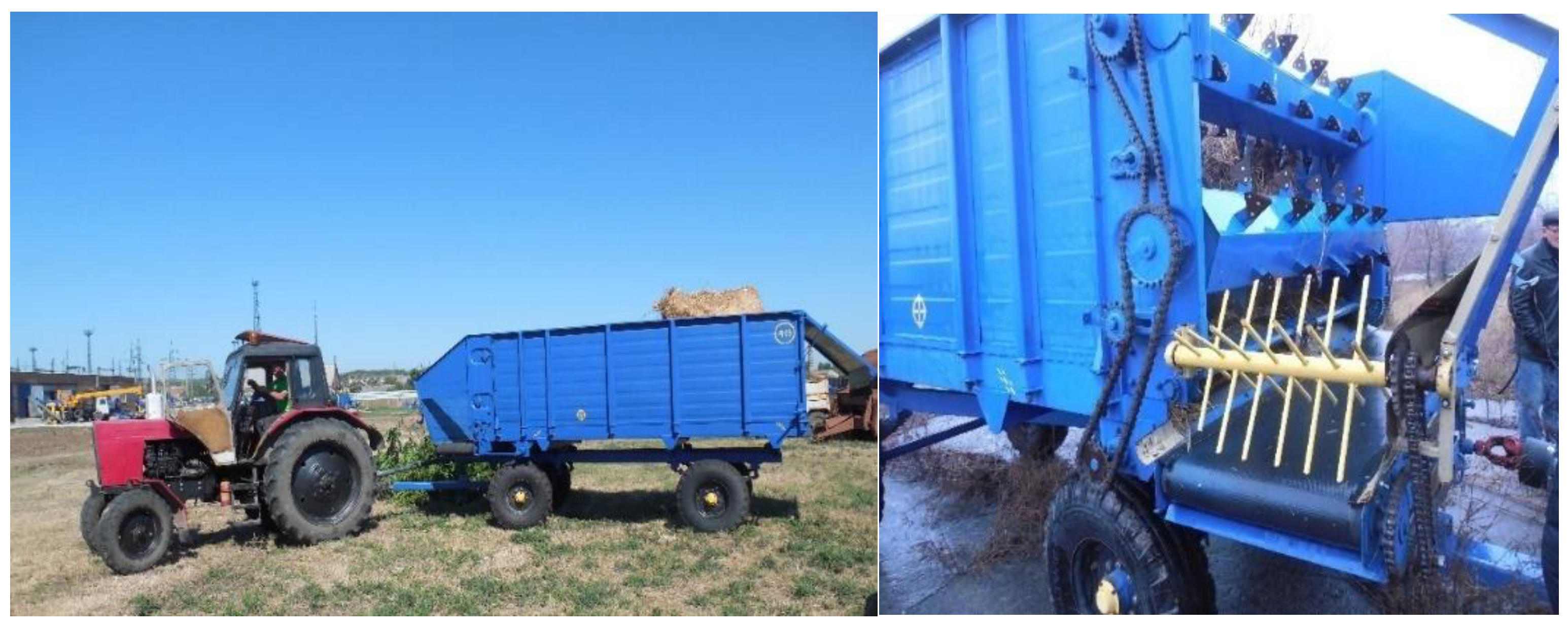
The Zaporizhzhya Research Center for Livestock Mechanization of NAAS of Ukraine, together with the Limited Liability Company “Orikhivsilmash”, produced the equipment for the technological process of making straw bedding on the farms of cattle on the basis of forage dispenser type KTU-10 (
Figure 1), specifications of which are presented in
Table 1. The working body for making the bedding is a rotor with four rows of fingers. The rotary finger working body is installed in the unloading window above the transverse belt conveyor in such way that the unloading mass is thrown from the conveyor by the working body, perpendicular to the direction of equipment movement [
1,
18].
Based on previous studies, it was found that for the qualitative spreading of bedding the rotor should have a diameter from 450 mm to 500 mm, with four rows sharpened at an angle of 15° to 30° of round fingers, which are radial to the axis of rotation. Thickness of the fingers should be no more than 14 mm, and the distance between them in a row from 50 mm to 70 mm [
18].
The equipment developed for the technological process of making straw bedding with a rotary finger working body is energy-saving and allows to reduction of energy costs. It also improves the quality of the technological process of spreading the bedding material from rolls. It also complies with the zootechnical and technological requirements.
The goal of our research is to determine the influence of design and mode parameters of the rotary finger working body on the energy consumption of the process of spreading the bedding material from rolls.
2. Materials and Methods
Experimental research program for energetic estimation of straw bedding spreader with rotary finger working body driven by tractor PTO is provided to perform the following tasks [
27]:
- -
to determine the power consumed to drive the rotary finger working body of the straw bedding mobile spreader;
- -
to determine the specific energy costs of the bedding material spreading process.
- -
Indicators of energy estimation were determined by the results of measurements obtained during the tests. At least four measurements of each parameter should be made on each operating mode of the agricultural machine or unit, lasting no less than 20 s [
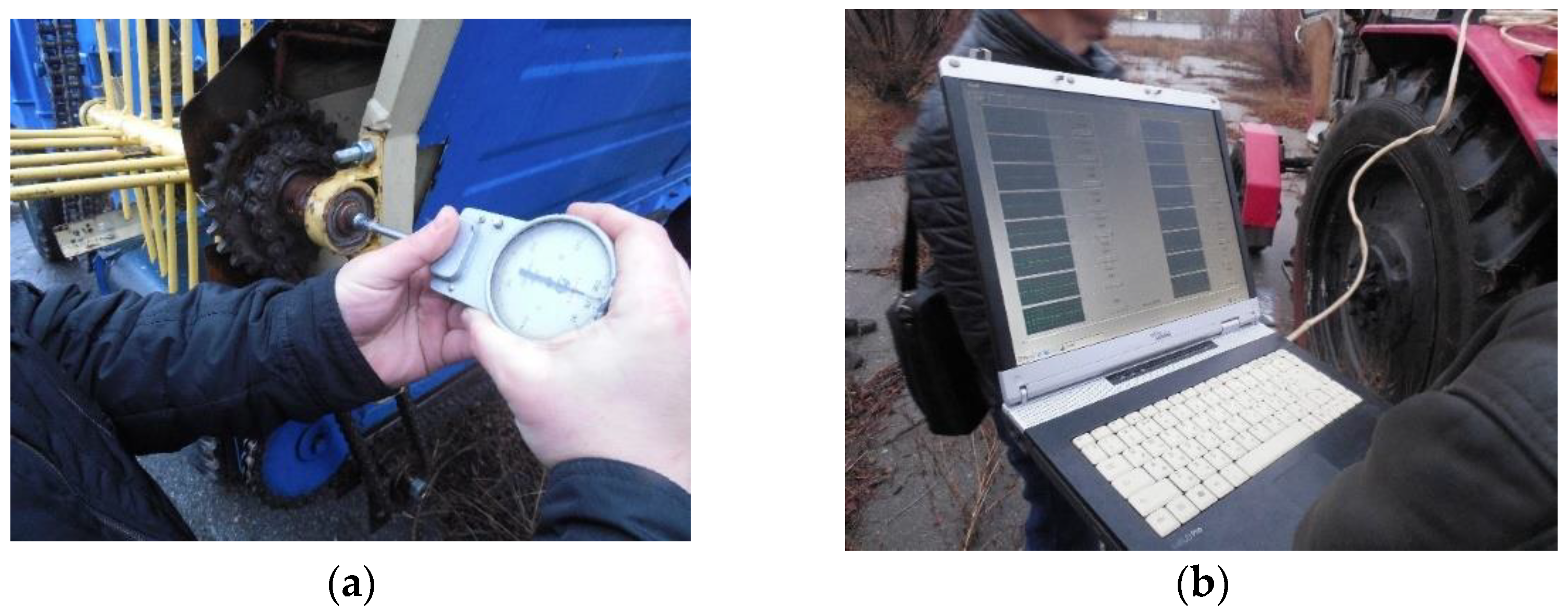
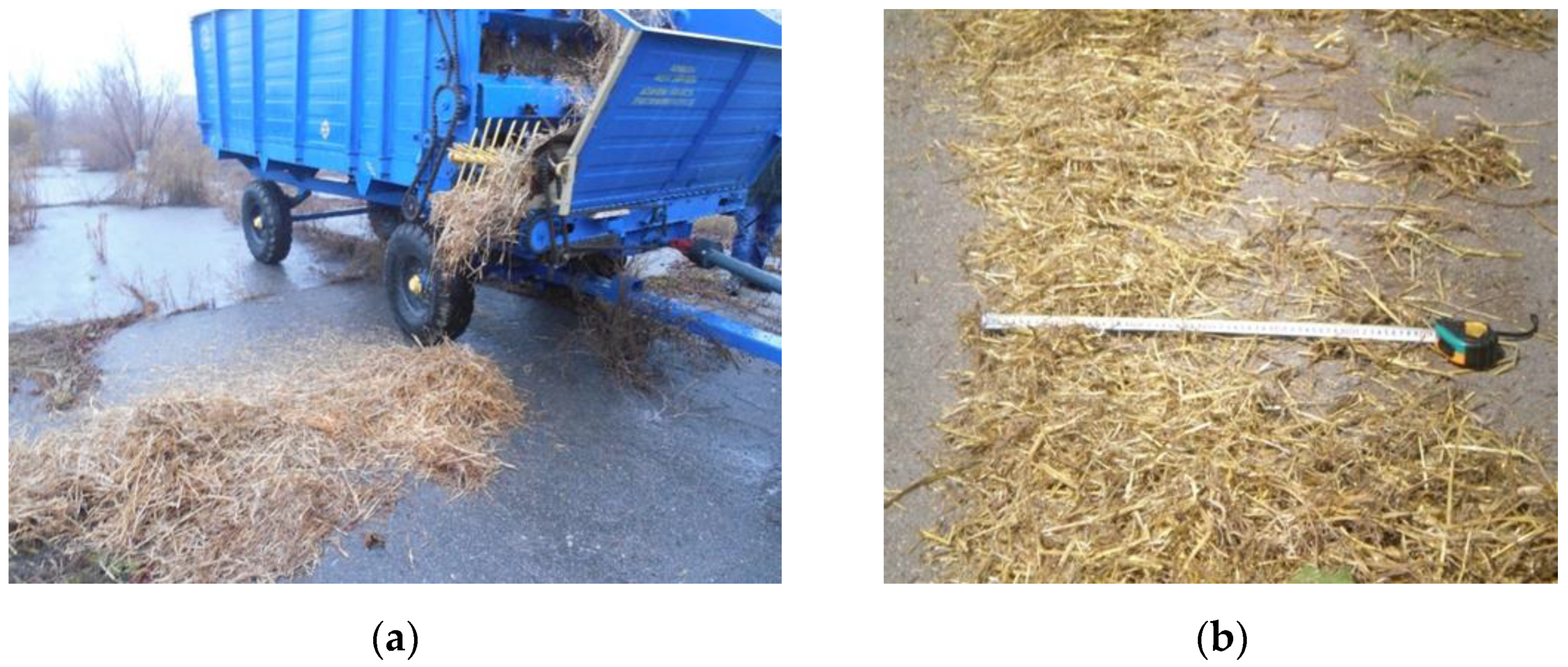
28]. When determining the energy estimation indicators of mounted, semi-mounted or trailed agricultural machines with working bodies driven from the tractor power take-off shaft, the following parameters are measured:
- -
time (duration) of measurement, using a stopwatch;
- -
track length, which passed by the mobile spreader of straw bedding during the measurement time and width of the spreading band, with the help of tape measure (
Figure 2) [
1,
27];
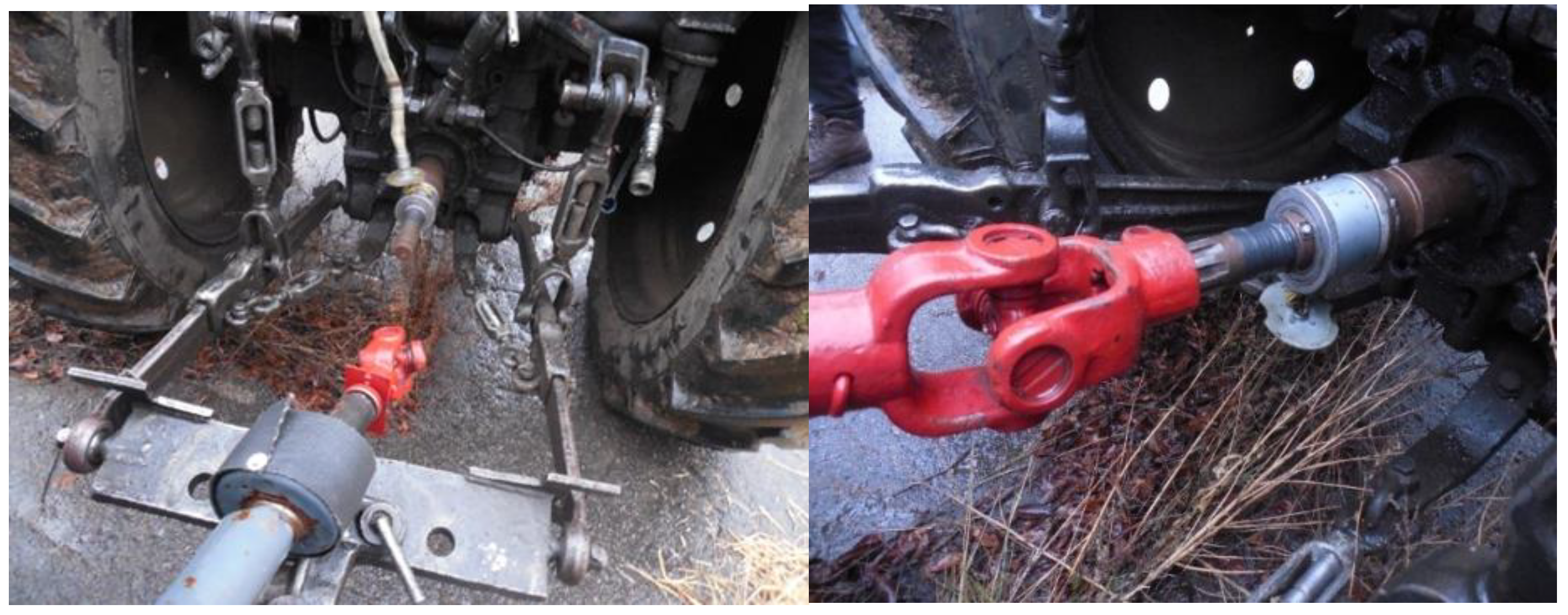
- -
torque on tractor power take-off shaft, by passing current collector of mercury amalgamated device (
Figure 3) [
27,
29];
- -
rotation speed of spreader working body shaft and tractor power take-off shaft, using a tachometer (
Figure 4a) [
27];
- -
data registration, with a PC (Notebook: Futjitsu-Siemens, Intel Core 2 Duo T-5500 1.66 GHz) and Oscill software (Version 1.26) (
Figure 4b) [
27].
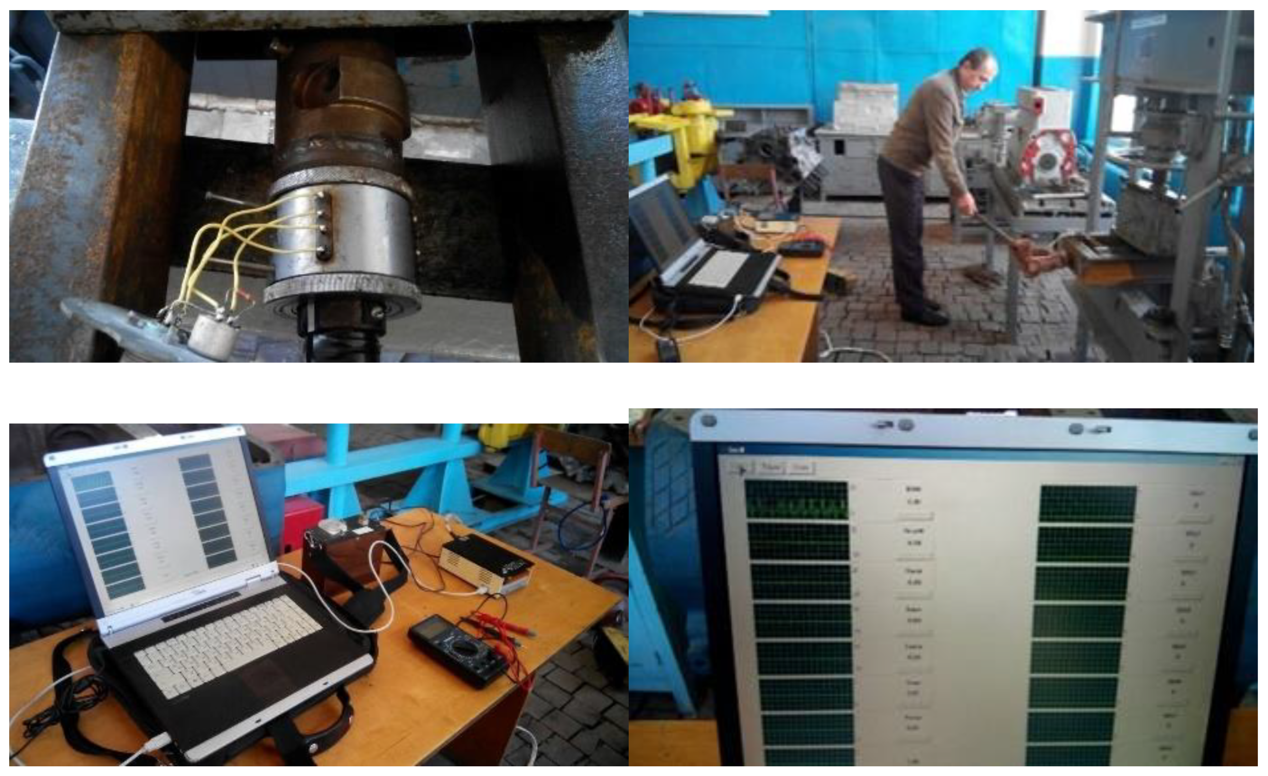
During machines testing, mercury amalgamated current collectors are widely used for installation on shafts of various diameters. A mercury amalgamated current collector has stationary and rotating copper contact rings, placed in a case with a radial clearance of 0.1 mm. Their contact surfaces are amalgamated; mercury between them is contained due to capillary properties. The contact rings are assembled in a block with organic glass rings. The movable part of the case of current collectors is installed on the shaft with strain gauges. The stationary part is connected with the movable part through bearings. The conductors from the rotating rings are connected to the strain gauges, and the conductors from the fixed rings are connected to the device. Experience of using current collectors with mercury baths showed that they provide reliable and stable electrical connection of resistors with measuring devices [
29]. This is why we used such a device for our own experimental studies. To ensure the data reliability of the mercury amalgamated current collector we have made a calibration of the device in the laboratory (
Figure 5) [
3].
3. Results and Discussion
Experimental studies of power estimation of the equipment with a rotor finger working body driven from a tractor PTO have defined the power consumed to drive a rotor-finger working body of a straw bedding mobile spreader, and have defined specific power costs of bedding material spreading process [
3]. For equipment with working bodies driven from tractor PTO, power (kW) is calculated by the formula [
27]:
where:
MPTO is the torque on the shank of power take-off shaft of the tractor, Nm;
nPTO rotational speed of the power take-off shaft of the tractor, min
−1.
Specific energy costs (kJ/kg) of straw bedding spreader with a rotary finger working body are calculated by the formula [
27]:
where:
NM is the power consumed by a straw bedding spreader with a rotary finger worked body, kW;
WO is the performance of the straw bedding spreader with a rotary finger working body, kg/s.
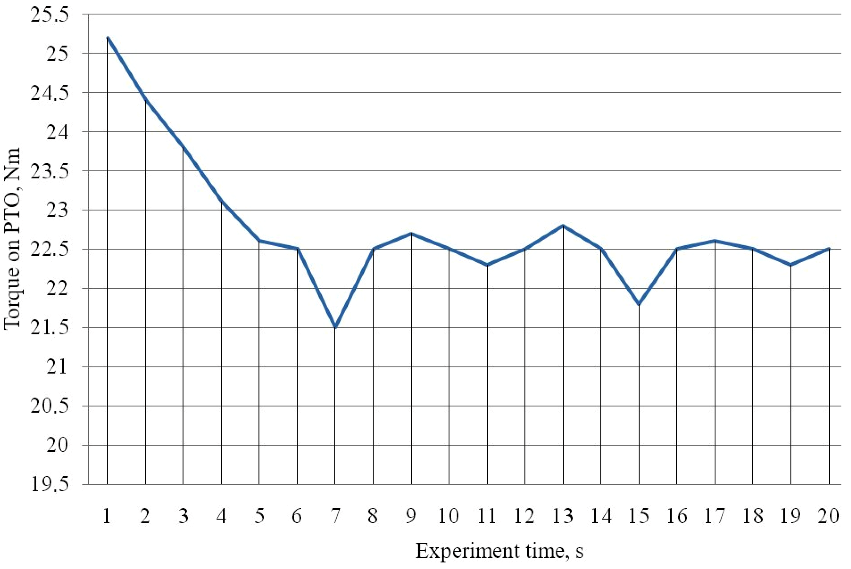
The torque reached its maximum value at 25.2 Nm in approximately 1 s after launching. Starting with 8 s of the experiment, the medium torque value was 22.5 Nm (
Figure 6). The rotation speed of the rotary finger working body with a drive transmission ratio of 0.6 was 324 min
−1. So, power consumed to drive the rotary finger working body of mobile straw bedding spreader is equal:
The results of experimental studies to determine the energy parameters of the mobile straw bedding spreader with a rotary finger working body are shown in
Table 2.
Experimental data analysis has shown (
Figure 6) that the most intense moment is the start of the mobile straw bedding spreader working body in case when the shank of the PTO reducer of the UMZ-8040.2 tractor is set to the rotation speed of 540 min
−1.
The research results of the influence of rotary-finger working device design and mode parameters on the energy consumption of the bedding material spreading process in graphical presentation are given in
Figure 7,
Figure 8 and
Figure 9, and consist of a pairwise dependence of the energy consumption on the rotation speed of the rotary drum ω, the radius of the center of mass δ, and an angle that complements to 90° the angle of the finger installation relative to the radius α
o (
Figure 7) [
3].
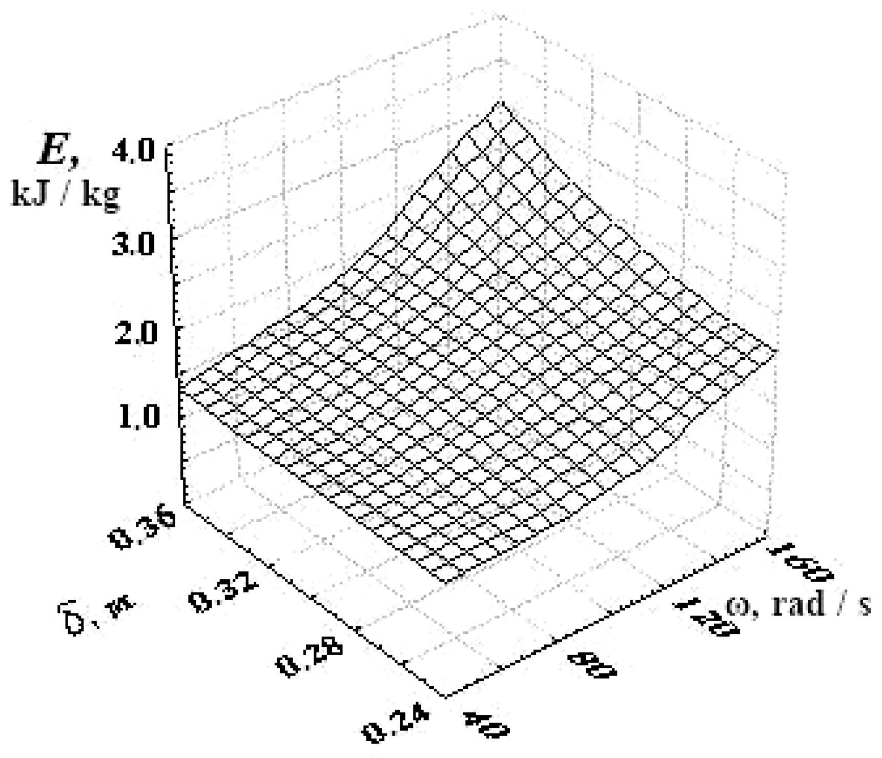
The analysis of
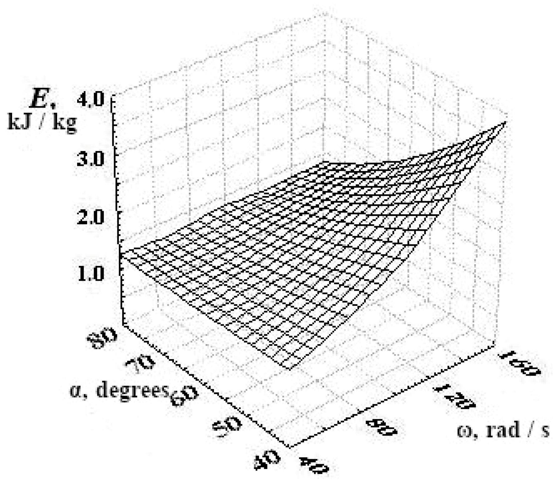
Figure 7 points to the fact that at low rotation speed of the rotary finger drum, increasing the radius of the center of masses, will not significantly increase the energy consumption, while with the growth of the drum rotation, frequency of more than 100 rad/s energy consumption of the process also significantly increases. This is due to the increase of the inertial component. The increase of energy consumption at high speeds with increasing radius of the center of mass is due to the increase of the effort required to overcome the growing torque. We also made a graphical interpretation of energy consumption dependence on angles complementing up to 90° the angle of finger installation relative to radius αo, and the rotation speed of the rotary finger working body ω with a constant radius of center of mass δ (
Figure 8).
Studying the graph of the dependence of energy consumption on the angle, complementing up to 90° the angle of installation of the finger relative to the radius, and the speed of the rotary finger working body, an identical tendency with increasing drum rotation frequency of more than 80–100 rad/s can be seen. That is, energy consumption begins to increase rapidly, because the increase in angle, complementing up to 90° the angle of installation of the finger relative to the radius to 80°, almost neutralizes the increase in rotation speed. This is due to an increase in the resistance force of the bedding slipping on the finger. Graphical interpretation, which is shown in
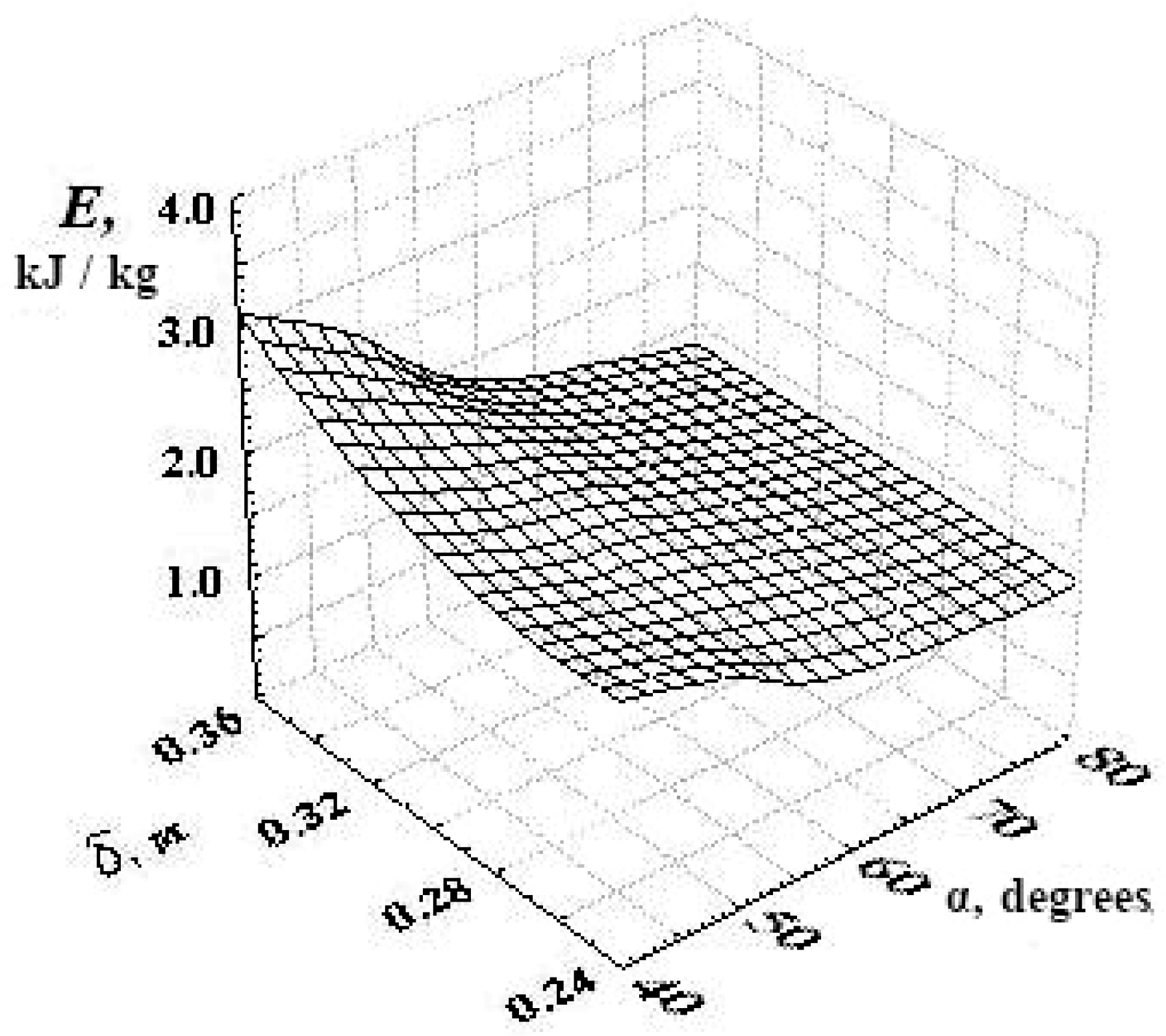
Figure 9, shows the dependence of energy consumption from the angle, complementing up to 90° the angle of installation of the finger relative to the radius, and the radius of the center of mass at a constant of rotation speed of the rotor finger working body.
Graph of the paired interaction of energy consumption with the radius of the center of mass and angle, complementing up to 90° the angle of installation of the fingers relative to the radius, shows the existing optimal angle of installation of the rotary working body fingers, which is in the range of 60°–65°. This allows us to obtain the specified productivity with a small energy consumption of the process of throwing the bedding, separated from the flow. Further, the increase in the radius of the center of mass also gives an increase in energy consumption of the bedding material throwing process.
4. Summary
Experimental data showed that the power consumed to drive the rotor-finger working body of the mobile straw bedding spreader in the forage spreader unit KTU-10A and tractor UMZ-8040.2, at a rotation speed of tractor PTO of 540 min−1, unit forward speed of 2 km/h, and performance of 1.5 kg/s is equal to 7.633 kW.
According to the basic model specifications of the forage spreader KTU-10A, power consumed to drive the working bodies is equal to 7 kW. In our case, due to the installation of a rotary finger working body for spreading straw bedding, power consumption has increased by 9%. This increase in power consumption will not have a significant impact on the overall energy consumption of the bedding material spreading process, as the nominal operating power of the tractor of this class according to its specifications is 57.4 + 3.7 kW.
The study of changes in energy consumption of the spreading process from the radius of the center of mass of a part of the bedding material and the rotation speed of the rotary finger working device indicate its insignificant increase (up to 2.1 kJ/kg) at drum rotation frequencies up to 100 rad/s, while a significant increase in specific energy consumption (more than 3.0 kJ/kg) will occur with increasing rotation frequency and center of mass radius of more than 100 rad/s and 0.3 m, respectively, due to the increased force required to overcome the growing torque.
The analysis of rotary finger working body rotation speed impacts on energy consumption of the bedding material spreading process indicates its significant increase (more than 2.0 kJ/kg) at the rotation frequency of 80–100 rad/s. That is, the energy consumption begins to rise sharply, because the increase in angle, complementing up to 90° the angle of finger installation relative to the radius of 80°, almost neutralize the increase in rotation frequency, all this is associated with an increase in resistance force of the bedding material slipping on the finger.
Energy consumption of separated bedding material spreading process in the stall (box) was E = 1.2–3.8 kJ/kg, and increased with a decrease in the angle, complementing up to 90° the angle of finger installation relative to the radius αo from 80° to 40°, which indicates on the existing optimal angle of rotary drum fingers installation, which is within 60°–65°.
The analysis of the existing machines for the application of litter of straw in livestock farms showed that this equipment has significant technological disadvantages:
- -
unstable and unreliable operation of the working bodies of the fans,
- -
no application of dosed litter,
- -
causes increased dust in production plants.
- -
It is therefore advisable to develop a litter spreader that works without the use of air flow with the possibility of dosing it into boxes. Reducing the size of the trusses will affect the service life of the spreaders with a rotary working body (low specific energy consumption). This solution will enable the implementation in practice of a significantly improved innovative technology, which:
- -
increases the efficiency of using plant materials as litter,
- -
reduces labor costs at the spreading stage,
- -
reduces the morbidity of animals,
- -
improves their living conditions,
- -
allows the use of tractors with lower power.
The developed experimental sample of a mobile straw litter spreader with a rotary-finger working body in accordance with previously conducted experimental studies fully meets zootechnical, technological and energy requirements, and can be recommended for implementation on livestock farms.
Author Contributions
Conceptualization, B.B. and R.S.; methodology, B.B.; software, R.S.; validation, R.S., N.B. and L.B.; formal analysis, S.D. and S.S.; investigation, S.G., T.J. and S.S.; resources, L.B.; data curation, T.J.; writing—original draft preparation, T.J.; writing—review and editing, S.S. All authors have read and agreed to the published version of the manuscript.
Funding
This research received no external funding.
Institutional Review Board Statement
Not applicable.
Informed Consent Statement
Not applicable.
Data Availability Statement
Not applicable.
Conflicts of Interest
The authors declare no conflict of interest.
References
- Pariev, A.; Drobyshev, O.; Korotchenko, T. Experimental studies of a litter spreader with a rotary-finger working body. MOTROL Commun. Mot. Energ. Agric. 2016, 18, 37–42. [Google Scholar]
- Pariev, A.; Boltianskyi, B.; Drobyshev, O.; Korotchenko, T. Experimental sample of a straw litter spreader. Design, production and operation of agricultural machinery: A nationwide interdepartmental scientific and technical collection. Kirovograd KNTU 2015, 45, 223–227. [Google Scholar]
- Scientifically substantiate technological processes and technical means of forming a combined litter to cover the stalls of cows, taking into account their physiological characteristics. Report on research topics 04.02.00.02P. Melitopol TSATU 2018, 21.
- Pariev, A.; Luts, S. Analysis and classification of straw bed spreaders for cattle. Mechanization, ecologization and conversion of biological resources in animal husbandry. Zaporozhye Inst. Fur. Anim. Husb. NAAS 2011, 1, 260–264. [Google Scholar]
- Pariev, A.; Voronin, L.; Korotchenko, T. Technological rationale for the use of a feed mixer-mixer for chopping straw into bedding for cattle. Mechanization, greening and conversion of biological resources in animal husbandry. Zaporozhye Inst. Fur. Anim. Husb. NAAS 2012, 2, 160–164. [Google Scholar]
- Boltianskyi, B. Advanced technologies as a basis for minimizing the total energy consumption in animal husbandry. In Proceedings of the IV Scientific and Technical Conference “Technical Progress in Animal Husbandry and Feed Production”, Glevakha, Ukraine, 14–20 December 2016; pp. 16–18. [Google Scholar]
- Skliar, A.; Boltianskyi, B.; Boltianska, N.; Demyanenko, D. Research of the cereal materials micronizer for fodder components preparation in animal husbandry. In Modern Development Paths of Agricultural Production; Springer: Cham, Switzerland, 2019; pp. 249–259. [Google Scholar]
- Pariev, A.O.; Korotchenko, T.M.; Drobyshev, O.O. Pat. 124539 IPC (2018.01) A01K 1/00. Equipment for litter application. applicant and patent owner ZNDCMT NSC “IAEE” No. u 201711427; declared 22/11/2017; public. April 10, 2018, Bull. No. 7. (Ukraine).
- Pariev, A.O.; Parieva, O.V.; Drobishev, O.O.; Boltianskyi, B.V.; Boltyanska, N.I. Pat.130749 IPC (2018.01) A01K 5/00. Feeder / applicant and patent owner ZNDCMT NSC “IAEE” No. u 201806374; declared 07/06/2018; public. 26.12.2018, Bull. No. 24. (Ukraine).
- Recommendations for the use of tethered-boxing technology for keeping cows. NSC “IAEE” NAAS Ukr. Zaporozhye 2013, 36, 23–25.
- Milko, D.O.; Sclyar, O.H.; Sclyar, R.V.; Pedchenko, G.P.; Zhuravel, D.P.; Bratishko, V.V. Results of the nutritional preservation research of the alfalfa laying on storage with two-phase compaction. INMATEH 2020, 60, 269–274. [Google Scholar] [CrossRef]
- Jakubowski, T. The effect of stimulation of seed potatoes (Solanum tuberosum L.) in the magnetic field on selected vegetation parameters of potato plants. Przegląd Elektrotech. 2020, 96, 166–169. [Google Scholar] [CrossRef]
- Matuszek, D.; Królczyk, J. Aspects of safety in production of feeds—A review. Anim. Nutr. Feed. Technol. 2017, 17, 367–385. [Google Scholar] [CrossRef]
- Jakubowski, T. The influence of microwave radiation at the frequency 2.45 GHz on the germination. Przeglad Elektrotechniczny 2018, 94, 254–325. [Google Scholar] [CrossRef]
- Popardowski, E.; Kwaśniewski, D. Technical-economic aspects of the eradication of energy willow plantations. In Proceedings of the 24th International PhD Students Conference (MendelNet 2017)/Cerkal Radim (Red), Brno, Czech Republic, 8–9 November 2017; pp. 808–813, ISBN 978-80-7509-529-9. [Google Scholar]
- Cupial, M.; Kowalczyk, Z. Optimization of selection of the machinery park in sustainable agriculture. Sustainability 2020, 12, 1380. [Google Scholar] [CrossRef] [Green Version]
- Nawalany, G.; Sokołowski, P. Improved energy management in an intermittently heated building using a large broiler house in central Europe as an example. Energies 2020, 13, 1371. [Google Scholar] [CrossRef] [Green Version]
- Pariev, A.; Drobyshev, O.; Korotchenko, T.; Boltianskyi, B. Approbation of a litter spreader with a rotor-finger working body in production conditions. Sci. Bull. TSATU Melitopol. TSATU 2018, 8, 74–81. [Google Scholar]
- Revenko, I.I.; Braginets, M.V.; Rebenko, V.I. Machinery and equipment for animal husbandry: A textbook; Condor: Kyiv, Ukraine, 2009; p. 731. [Google Scholar]
- Revenko, I.I.; Rohovyi, V.D.; Kravchuk, V.I. Design of mechanized technological processes of livestock enterprises. Harvest 1999, 192. [Google Scholar]
- Guz, M.; Marchenko, V.; Music, A. Technique for preparation and distribution of feed. J. Agroexpert Pract. Guid. Agric. 2014, 1, 66–71. [Google Scholar]
- Muzyka, A.A. You lay softer—You get more milk. Livest. Russ. 2002, 6. [Google Scholar]
- Tishchenko, M.A. Rationale for shredder-mixer-distributor of rolled and concentrated feed for cattle farms with hay-concentrated type of animal feed. Econ. Organ. Technol. Mech. Anim. Husb./Azov-Black Sea State Agroeng. Acad. Zernograd 2008, 4, 146–153. [Google Scholar]
- Tishchenko, M.A.; Sergeev, M.F. Litter spreaders on cattle farms. Mach. Agric. 1982, 10. [Google Scholar]
- Sukhorukov, V.V.; Gorbulina, N.A.; Kolomoets, I.I. The results of research on the choice of the working body of the litter spread. In Scientific and Technical Bulletin on Mechanization and Electrification of Agriculture Zaporozhye-Communard; Kyiv, Ukraine, 1981; Volume 16. [Google Scholar]
- Sukhorukov, V.V.; Matusevich, V.E. Device for spreading litter. Avt. sv-vo № 1985, 1156755.
- Boltianskyi, B.; Dereza, S. Program and methods of experimental research to determine the energy performance of litter spreader. Sci. Bull. TSATU Melitopol. TSATU 2020, 10, 68–75. [Google Scholar]
- Boltianskyi, B.; Shpyganovich, T. Nomogram method of analysis of the results of a multifactorial experiment of TSATU. Sci. Bull. TSATU Melitopol. TSATU 2012, 12, 64–68. [Google Scholar]
- Nadicto, V.T.; Kryzhachkivsky, M.L.; Kyurchev, V.M.; Abdullah, S.L. New mobile energy resources of Ukraine. In Theoretical Bases of Use in Agriculture: Textbook. Manual; MMD Publishing House: Melitopol, Russia, 2006; Volume 337, pp. 112–119. [Google Scholar]
| Publisher’s Note: MDPI stays neutral with regard to jurisdictional claims in published maps and institutional affiliations. |
© 2021 by the authors. Licensee MDPI, Basel, Switzerland. This article is an open access article distributed under the terms and conditions of the Creative Commons Attribution (CC BY) license (https://creativecommons.org/licenses/by/4.0/).

 and
and 


