Article

Design and Optimization of a Curved-Crease-Folding Process Applied to a Light Metallic Structure

by
Doina Raducanu
1,
Vasile Danut Cojocaru
1,
Vlad Andrei Raducanu
2,*,
Anna Nocivin
3,
Nicolae Serban
1,
Ion Cinca
1,
Elisabeta Mirela Cojocaru
1,
Laurentiu Moldovan
4,
Corneliu Trisca-Rusu
5 and
Irina Varvara Balkan
1
1
Materials Science and Engineering Faculty, University POLITEHNICA of Bucharest, 060042 Bucharest, Romania
2
Faculty of Decorative Arts and Design, National University of Arts, 010702 Bucharest, Romania
3
Faculty of Mechanical, Industrial and Maritime Engineering, Ovidius University of Constanța, 900527 Constanța, Romania
4
Rodax Impex SRL, 052167 Bucharest, Romania
5
National Institute for Research and Development in Micro-Technologies, 077190 Bucharest, Romania
*
Author to whom correspondence should be addressed.
Processes 2021, 9(7), 1110; https://doi.org/10.3390/pr9071110
Submission received: 6 June 2021 / Revised: 22 June 2021 / Accepted: 23 June 2021 / Published: 25 June 2021
(This article belongs to the Special Issue Design and Optimization in Process Engineering)

Abstract

:
Presently, the realization of complex, unconventional designs using efficient modalities is possible due to an increasing interest in interdisciplinary approaches: materials science, mathematics, IT, architecture, etc. Computerized techniques, among which the algorithmic/generative design is the most advanced one, that are associated with the individualized production methods are used for finding solutions for modern spatial forms with an unconventional spatial geometric shape, which are generically called “free-forms”. This work presents the design, realization and testing of a thin-walled metallic structure proposed as a light structural unit. An integrated research approach was proposed that utilized an algorithmic/digital design applied to the curved-crease-folding method with the study (at different length scales) of the metallic material behaviour after folding. An original method was proposed for the digital design and simulations. The specific mechanical behaviour of the metallic material in the elastic–plastic regime was used in this case to improve the structural performances; mechanical and structural tests were realized to analyse the behaviour of the entire structure. The results are useful for enhancing the accuracy of the digital design, the structural simulation programs and the fabrication methods.

1. Introduction

Constitutive parts of the metallic structures need innovative technologies for their design and realization, together with a deep understanding of the specific features of the materials’ behavior. A possible topic idea could be to create intelligent, easy-to-process and highly efficient forms for the intended purpose. To fulfill this purpose, a new approach called parametric or algorithmic design is used for overcoming many limitations. If the latest advancements in material science are integrated into this approach (a difficult task, already), new flexible design models as part of complex production programs are realizable.
Complex spatial structures often have free-form surfaces [1,2] with an unconventional spatial geometric shape; they play a prominent role in contemporary design and can be designed via algorithmic or generative design [3,4,5,6,7,8]. Generative design (GD), also called algorithmic/computational design or parametric design [9,10,11,12,13,14], is a new class of digital design media and associated software tools that are totally different from the conventional CAD (computer-aided design), CAM (computer-aided manufacturer) and CAE (computer-aided engineering) procedures. Using GD, one can represent 3D objects by using object-generating operations according to mathematical algorithms. A shape, in this case, a free-form type, is described by a sequence of processing steps. Rhinoceros, the main modeling medium in GD, works nowadays with Grasshopper extensions (Karamba, Kangaroo, Geometry Gym) that are specialized for structural analysis based on a generative mode (algorithmic, parametric and automatized) that is a different approach from numerical mathematical methods/analysis (FEM–finite element method, or similar). Therefore, structural data for many parameters can be provided. The specific properties of the generative systems are: the ability to generate complexity; the ability to self-maintain and self-repair; the ability to generate novel structures, behaviors, outcomes or relationships [10,15,16,17].
However, for operating in generative/parametric design, advanced expertise and knowledge are presumed regarding: mathematics, smart geometry, physical systems codes and rules and IT abilities regarding operating with dedicated software. Another important mention refers to material properties and behaviour integration in the design process. For this, complementary knowledge about material science must exist and even then, the problems remain difficult.
A modality to generate complex free-forms from different materials is curved-crease folding (CCF) [18,19,20,21,22], which is a method that is a mixture of folding and bending, resulting in a spatial surface with curved creases and smooth curved developable surface patches.
Folding is developed along spatial curves [19,23,24,25], not along straight lines. CCF is an expanding scientific research domain that is not yet fully theoretically established.
Inside the whole process of spatial form-finding, the digital simulation of the deformations that arise when a metallic material is folded along curved lines is complex. For this reason, working with physical models is often the starting point in the design process.
The simplest scenario for the curved folded surfaces obtained is when the fold lines result from the intersection of a developable surface with a cutting plane. In this case, the result is the reflected geometry of one of the two sides [26], as can be seen in David Huffman’s cone designs [27] (Figure 1a) and Philip Chapman-Bell models [28] (Figure 1b). Using multiple sectioning and the reflection of a cone, a curved folded pattern results (which is ultimately a developable area for a flat development).
CCF is, however, an underexplored topic. Folding techniques have the potential to be widely applied to engineering, architecture and object design. The precedents for folding along curves are for paper and some other materials, but their physical shapes are poorly understood [29,30,31,32,33]. One of the difficult problems to explain mathematically in the case of curved crease folding is that the surface cannot be represented using simple parameters, such as NURBS (non-uniform rational B-splines) surfaces, because of the restrictive constraints induced from its geometry [30].
The CCF technique has the potential for realizing complex structures using different materials, but it is still at the beginning; usually, a trial and error approach is applied. Therefore, the analysis of the complex forms using computational means associated with advanced processing methods, such as digital fabrication (computer numerical control (CNC) or robotic equipment for the folding process) [34,35,36,37], will lead to progress in this domain. Generative design can be applied to the CCF process, but the most challenging task is to integrate, understand and explain the specific behaviour of materials.
Obtaining useful applicative results is rather difficult to achieve in a single research line due to all the aspects pointed out above because different and often antagonistic information must be managed from: mathematics, IT, engineering and material science. During a far-reaching approach, some important stages should be accomplished:
-
The realization of an algorithm based on generative methods that are able to describe the curved-crease-folding process;
-
Describing the material’s behaviour in the algorithm;
-
The selection of suitable production methods for spatial structures realization.
In our study, all these steps were completed to develop an experimental model of a metallic structure, namely, a column-like one, consisting of six metallic elements that were folded following curved paths.
An original method was developed for the generative digital design stage of the curved-crease-folding process for the constitutive elements of the experimental model. A specific technological method was designed for the experimental model realization. Then, different mechanical tests were performed to study the local and global mechanical behaviour of the metallic material at curved crease folding for the constitutive elements of the experimental model and to analyse the entire structure’s response to loading. Detailed results from the analysis of the above aspects are presented in this paper.

2. Materials and Methods

For the present study, a metallic material (Fe360 (CEN-EN)/A283 (USA ASTM, ArcelorMittal Galati, Romania) was used for realizing the experimental model of a thin-walled metallic structure, namely, a column-like one, with a spatial shape that is reminiscent of the columns used in the classical architectural orders and with transparency through the openings that appear in the bulging section of the column (Figure 2b (right)). The aims were:
-
The development of an algorithm for the curved crease folding design;
-
The analysis of the material behavior after folding at different length scales from micro/mesoscale to macroscale level in the proximity and at a distance from the folding paths;
-
The development of a production method for the experimental model realization and specific testing of the spatial structure to validate the design.

2.1. The Development of the Curved-Crease-Folded Surfaces Using Digital Design

This section of the article presents the generative digital design of the spatial metallic structure that was realized using the CCF method.
The main steps for the digital design stage for the spatial metallic structure were as follows. Several preliminary designs [38,39] were produced using algorithmic tools and different models were made from cardboard (Figure 2a,b); they represent possible column shapes to be further realized using curved folded sheet metal. The shape seen in Figure 2b (right) was chosen [40,41] having in view possible future applications of the object in a built environment.
The steps of the virtual simulation of the CCF process [42] were as follows:
-
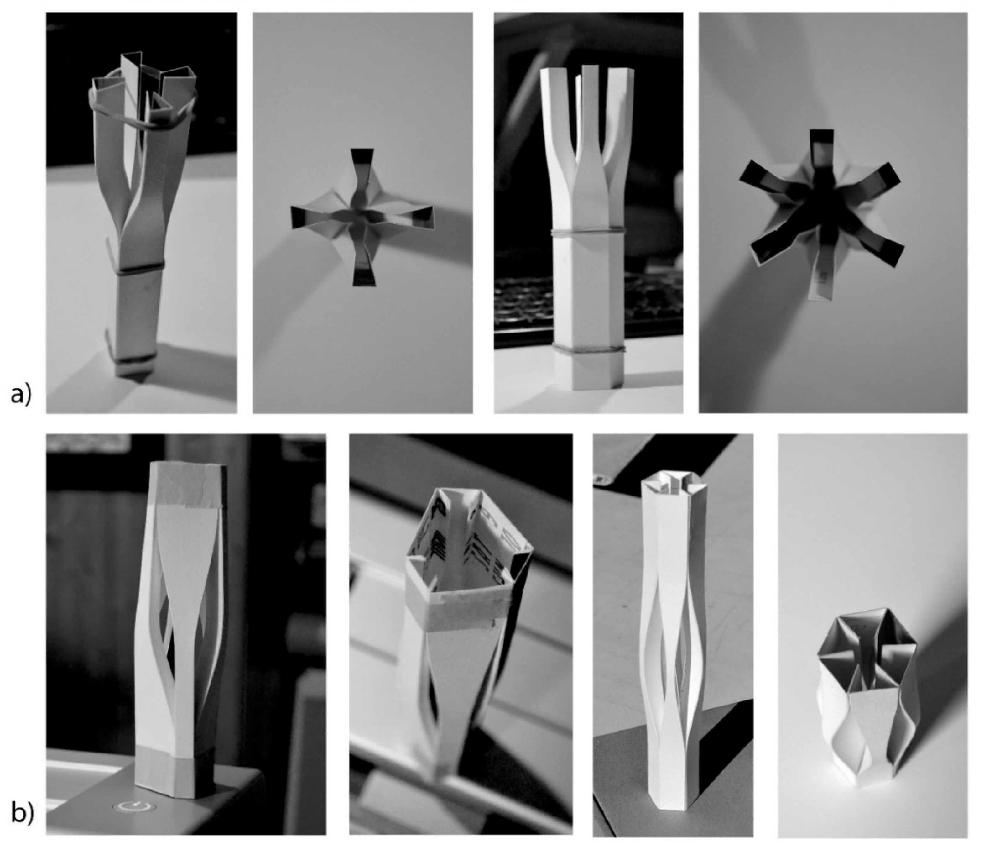
Initially, a design solution was sought using physical models (usually cardboard models).
-
Once a plausible idea arose, the planar development was digitally generated (understood as a two-dimensional shape that could be folded into a three-dimensional shape, also called the “net” of the crease-folded element), preferably in an algorithmic manner; this approach allowed for easily changing many parameters. The planar development/the net with the folding trajectories that were already marked was a key object in the design process. Depending on the design accuracy and the material’s intrinsic mechanical properties, the result may or may not the expected one.
-
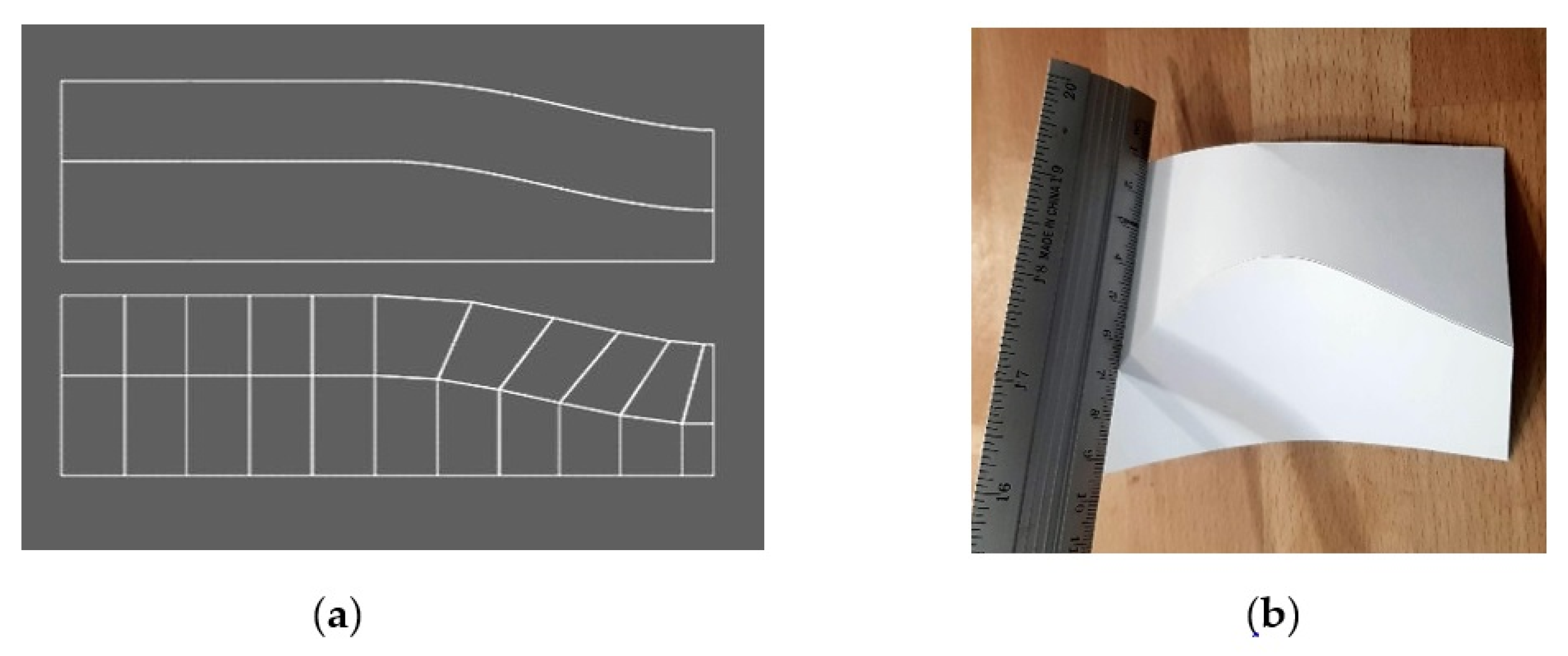
The simulation of the curved-crease-folding process took place using an interpretation/conversion of the planar development (that would be used for fabrication) as a rigid origami pattern (Figure 3a (bottom)). No analogies with the numerical simulations (FEM, for example) could be done. Rigid origami uses polyhedral planar plates that are joined by rectilinear hinges [43]; just for the rigid origami pattern, everything was based on straight lines.
-
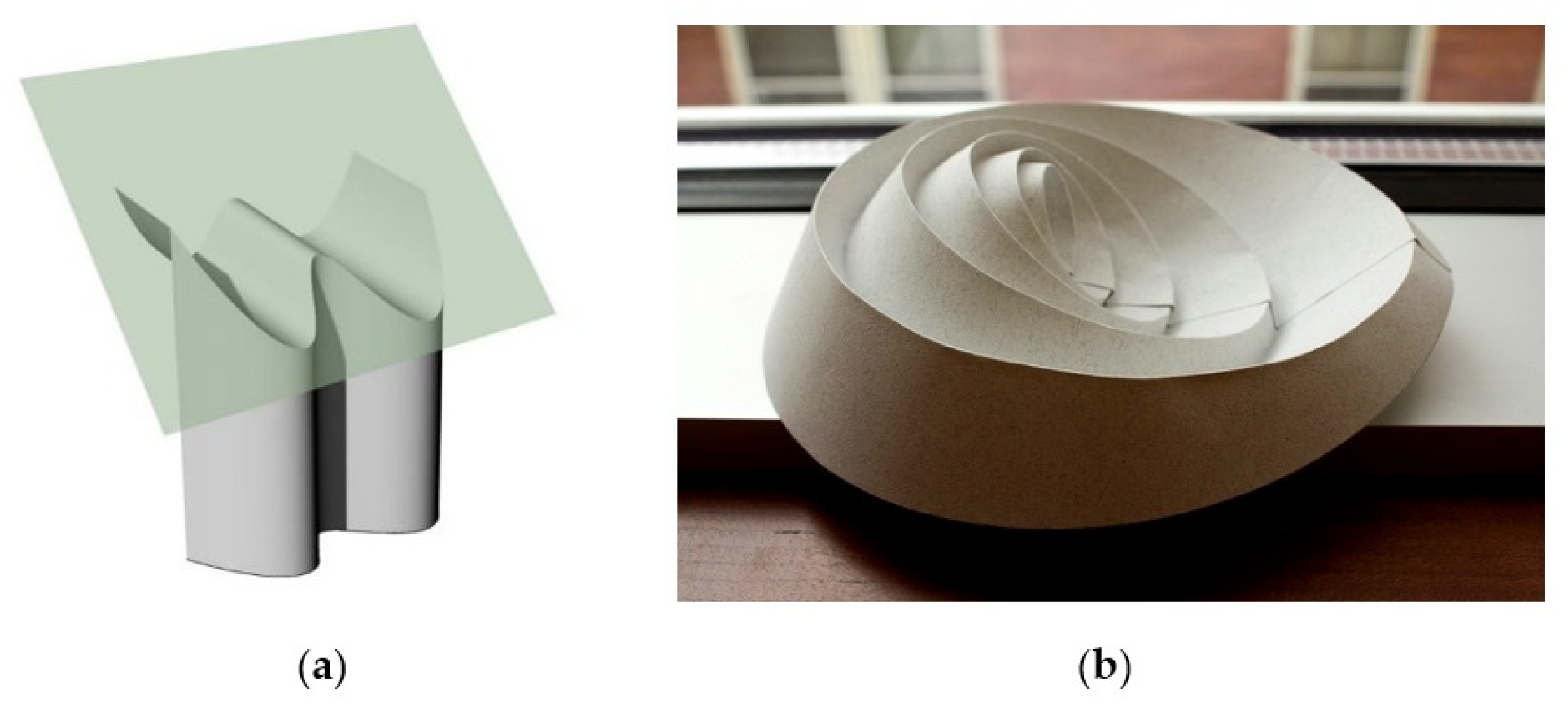
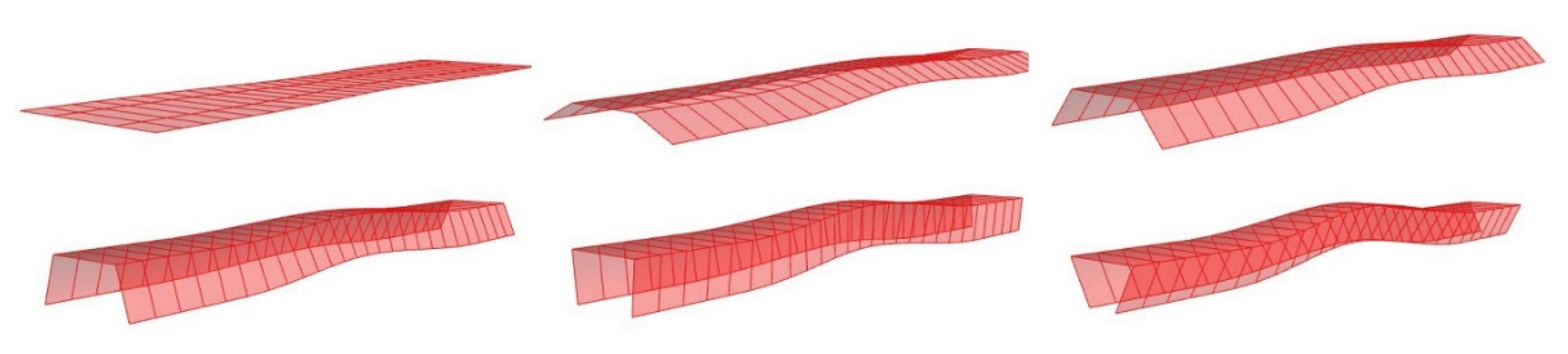
The above conversion required the so-called “ruling lines” of the curved folded spatial shape (Figure 3b). A particular curved crease planar development did not describe a single possible folding outcome (Figure 4); it depended on the way the first strip/surface was bent. This, in turn, determined the shape/curvature of the adjacent piece, and so on. In any case, the outcome was a ruled surface, which was therefore developable and integrated the ruling lines.
-
Different folding variations of the same planar development exhibited differently oriented ruling lines, which changed their orientation depending on the curvature of the strips that formed the overall shape. This means that the “rulings pattern” determined the way in which the planar development was digitally folded; more specifically, it determined the way the separate strips/parts of the planar development were folded/bent during the folding process.
-
The orientation of the ruling lines on the planar development could be transferred in the digital representation.
-
Digital analysis: at this stage, the planar development (converted initially into polyhedral planar plates joined by rectilinear hinges, i.e., a rigid origami) was folded digitally/virtually; after the virtual folding, the folded element could be subjected to different analyses, either structural or otherwise.
The process of the spatial form finding generated different models for the curved folded design for our study (Figure 2b). The authors focused on the possibility to realize the experimental model of a free-form metallic column using the curved-crease-folding process. The design also benefited from the natural flow of the metallic material under tension, which generated smooth surfaces that added an aesthetic value, especially since sheet metal has reflective properties that highlight the curvature.
The end design (Figure 2b (right)) used a hexagonal footprint so that it better illustrated the idea of a circular section (rather than quadratic or triangular), which is specific to the concept of a column, but also because it presented a three-axial symmetry [44].

2.2. Algorithmic Design of the CCF Thin-Walled Metallic Structure

The general algorithm was developed so that fewer symmetrical designs could be employed (i.e., that had a wider/longer bottom part of the constitutive element). This paper presents only the parts of the algorithm that were relevant for the presented design. The study aimed to generate all possible designs while keeping the visual identity of the design. The 3D modeling software used was Rhinoceros 3D and the plugin used to define the algorithm was Grasshopper. Grasshopper is a node-based visual programming tool that provides basic (geometric, mathematical and data management) functions that were used to develop the algorithms. There are also other plugins that expand the capabilities of Grasshopper, such as Kangaroo and Karamba, which were both used in the process (Kangaroo for the digital bending and Karamba for the stress analysis). Some explanations are presented in the Supplementary Materials attached to this article.

2.2.1. The Algorithm for Rationalized Planar Development

The metallic column was based on a number of strips (in this case, six) that had a symmetrical arrangement of the folding lines (Figure 5), which eased the determination of the “ruling lines” needed for the digital/virtual folding simulation.
Obtaining the planar development with the final folding trajectories was done algorithmically.
Figure 6 shows a flow diagram for the part of the general algorithm dedicated to obtaining the folding paths on the planar development.
This part of the algorithm generated one of the six planar elements that formed the column. The algorithm started with a line with the final length of the planar development, which was the precursor to the folding line. On this, a segment was cut in the middle part of the planar element where the folding line was to be curved. The extremities of this segment were defined using user input data. The middle segment was replaced by a curve that was generated using a cosine function. The three “segments” were joined to form the completed folding line, which was mirrored. The outside boundary was then generated, which was based on the desired lateral flaps’ widths. This planar development went further into the general algorithm to be digitally folded using the curved creases.

2.2.2. Concept of the Digital/Virtual Simulation of Curved Crease Folding for the Constitutive Element of the Column

The simulation of the curved-crease-folding process used a conversion of the planar development as a rigid origami pattern, which used polyhedral planar plates joined by rectilinear hinges.
Rotating anchor points around the folding lines at the base of the strip determined a chain reaction through the entire model due to the implemented rigid plate origami behaviour. The folding angle was not constant along the crease [42]. According to the way the planar development was folded, there were a couple of principles [42] that related the orientations of the ruling lines (Figure 7): a straight line in the crease pattern (ruling pattern) could not be bent; the curved fold was twisted when the rulings had kinks at the rulings. Both were taken into consideration for the algorithm, and the digital simulation did return an acceptable approximation of the physical model (Figure 8). In this way, the algorithm included an automated adaptation of the ruling lines pattern that generated the planar development (which was the key object necessary for the starting point of the curved folding process).

2.2.3. The Development of the Algorithm for Digital Curved-Crease-Folding Simulation

Once the rationalized planar development was generated, a planar quadrilateral mesh could be developed on it and then digitally folded [45].
The deformation (folding) can be performed using a specific origami software, such as Freeform Origami and Rigid Origami Simulator [46], but the Kangaroo plugin for Grasshopper can also be used in some steps of the algorithm; however, Kangaroo can simulate deformations mainly for post-folding analysis. Figure 9 illustrates the flow chart for the algorithm of the digital folding simulation with the connections that was used to digital simulate the geometries and behaviours. The algorithm for the digital CCF simulation is a specific part of the general algorithm.
The planar quad mesh method [42,47], which is based on the Tachi/Kilian method [42], was used for simulating CCF to obtain the three-dimensional folded shape (Figure 10a). The developed algorithm for this study implemented resistance to folding (a material property) in a digital manner using specific digital instrument development. The main steps (named “goals” in Kangaroo) of the digital simulation of the CCF process are as follows:
-
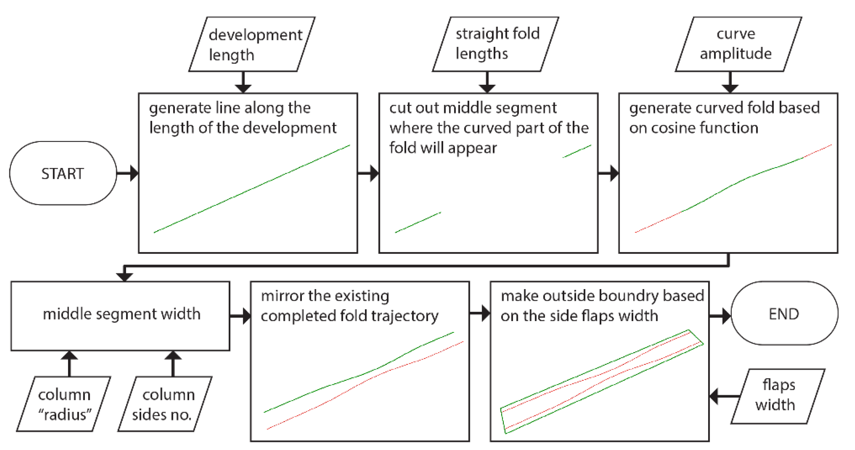
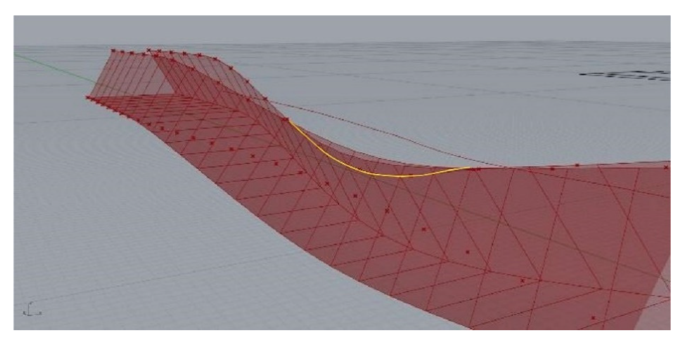
A set of points on the lower straight segments of the folding lines are used as anchors, meaning they keep the mesh in place when it gets folded.
-
Their counterparts on the upper straight segments are able to slide toward the middle as the mesh folds and therefore compress longitudinally, but they are not allowed to migrate away from the area where they are originally located.
-
Kangaroo works on assembles made of “springs,” which are straight-line segments that can be rigid or flexible; the mesh is interpreted as a network of rigid springs along the edges of the quads, but rigid springs are also generated on the diagonals to ensure they do not skew during the process.
-
A “planarize” component is also used to ensure the quad faces remain planar when the folding occurs so that they reproduce the mechanics of real-world rigid plate origami (which can estimate a curved folding process).
-
A “plastic hinge” goal is used that implements a limited resistance to the folding of the model.
-
A solid point collide goal is used so that the points on the lateral flaps of the development/mesh are pushed by two virtual “banks.” These banks are a pair of boxes/parallelepipeds that will gradually rotate (via user input) to fold the mesh into place. The folding process should be gradual, from the initial flat net to folded one, allowing for providing a relevant shape of the mesh with Kangaroo. The final folding angle cannot be used directly.
-
After the conditions for folding are defined and Kangaroo (compiler) is running, the angle is gradually increased until it reaches its end value, which is based on the number of sides of the column.
-
After the mesh is folded, it is reproduced in a circular array to display the column as a whole.
The developed algorithm virtually implements the metallic material resistance to folding in the digital folding process. The method used to bend the steel sheets in place involves folding the end parts (with the rectilinear folding trajectories) using a virtual tool for progressive bending while the middle part of the folded element conforms. However, the angles of the end parts do not propagate fully where the virtual tool is not used for progressive bending due to the material’s resistance.
Therefore, the rectilinear parts at the extremities of the planar developments were bent with a specific angle, while the midsection, which was governed by curved folding lines, bent to another angle. This generated an additional problem because the lateral strips tended to splay in the midsection (Figure 10b), which led to overlapping when they were used as a six-piece ensemble. This issue was resolved using virtual banks (grips) as digital instruments to digitally/virtually fold the flat sheet into place (Figure 10c).
Finally, the planar development was generated algorithmically (using Grasshopper and Kangaroo) to easily modify the column proportions and generate the variations of the fold paths’ trajectories.

2.3. Post-Folding Analysis

A metallic material changes its properties when it is folded (where the creases are, between the gaps); furthermore, additional tension is induced in the material when it adopts a curved shape. Therefore, it is very difficult to make a simulation that considers all these aspects; as such, physical testing of a real-world model is necessary. As concerns the simulation programs available at present for the post-folding analysis of a digitally folded element, some of the following items are not yet implemented:
-
The gradient of properties in different areas of the folded element.
-
The additional tension gained after folding; this was partially implemented by some authors just for certain particular designs [48].
-
The influence of the solid–void ratio for the case in which the folding lines are marked on the physical planar cut-out using perforations.
However, the post-folding simulations can predict where the weak spots are on the design and can steer the design process for the models/prototypes toward a more efficient solution.
The purpose of the analysis was not to reproduce the folding process but to identify the weak spots of the ensemble for future modifications of the design given that the metallic material behaviour is totally different during and after folding than before folding.
During the folding process, the real deformation of the metallic material is complex, with a gradient from undeformed areas to permanently deformed areas. This behaviour was solved using the developed algorithm for digital folding simulation. The behaviour of the metallic material was completely different at post-folding; the folded element behaved elastically until the collapse/failure moment. This behaviour was also shown in the experimental results, which are described further in this article.
The model that was introduced in Karamba was the final (already digitally folded) element of the column with the dimensions (1 m in height) of the experimental model.
Kramba3D [49] uses a given (folded) mesh geometry without taking into consideration the digital process that led to the final shape.
The computational analysis done in Grasshopper using Karamba [49] showed that the middle section was where the stresses and deflections arose (Figure 11 and Figure 12). The goal was to implement the bending stresses that occurred due to the sheet material, which transformed from the flat state to its curved state. Therefore, the intersection contour of the two sides must be extracted, which is easily done in the digital realm once the digital folding simulation is complete (Figure 11).
Using this intersection path, the quadrilateral mesh was stripped and could be welded in that area. Two scenarios (welded and non-welded) could be structurally tested and compared by using Karamba. By applying the same axial force on the two models, the deflections and internal stresses [49] were compared and it was revealed that the welded solution performed two to three times better than the non-welded one (Figure 12a,b).
Once a satisfying shape was reached, Karamba was also used to determine the needed material thickness to withstand the anticipated load of the column. The metallic material thickness affected the ease with which the surface curvatures were formed and the bending process along the folding path (noting that the bending angle varied along the folding path).

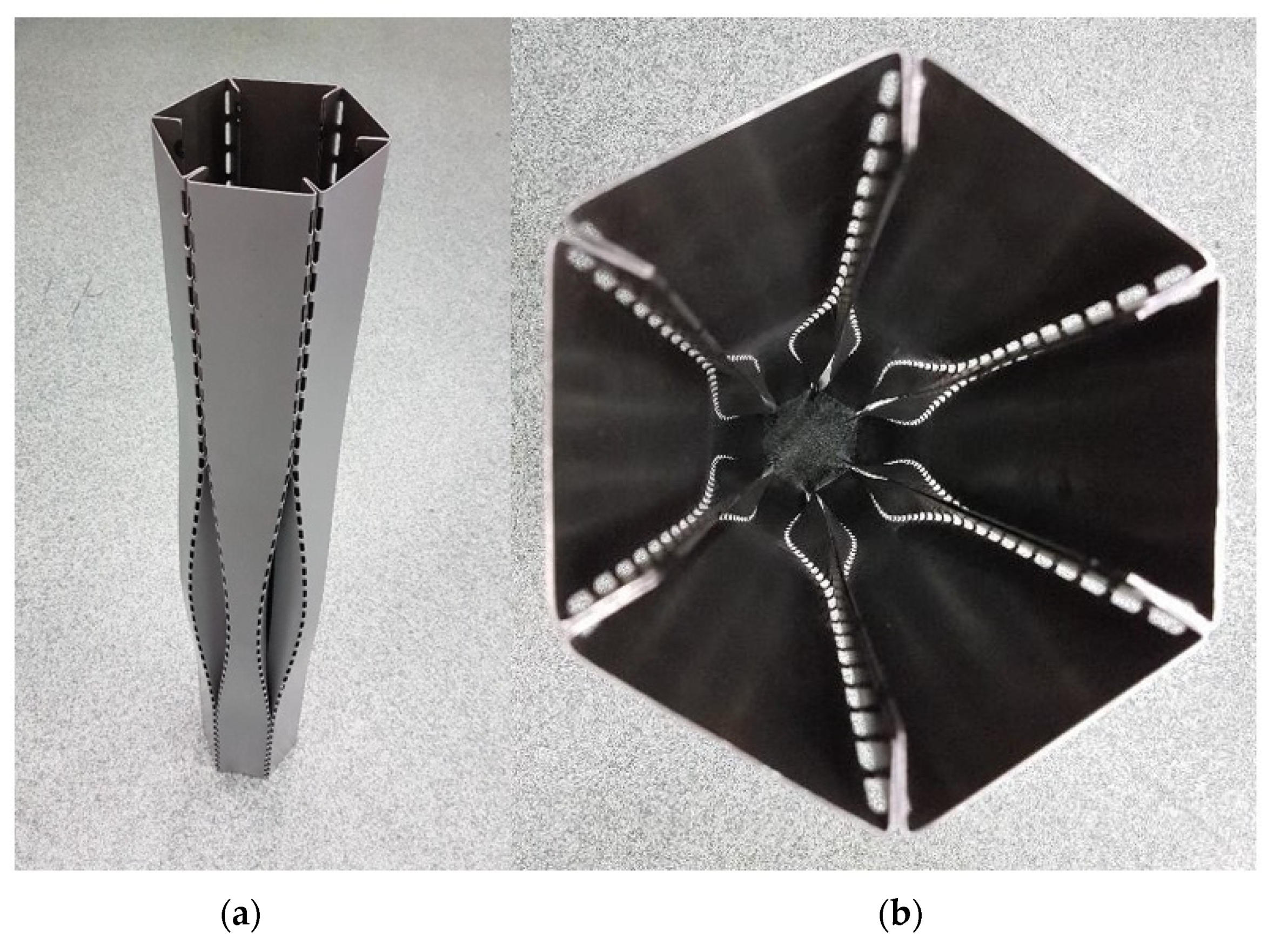
2.4. The Thin-Walled Metallic Spatial Structure Fabrication

The metallic material used for the spatial structure fabrication was a 1 mm thick sheet of Fe360 (CEN-EN)/A283 (USA ASTM, ArcelorMittal Galati, Romania), which is a common alloy used for stamping.
The fold paths’ trajectories needed to be transferred from the digital design to the physically developed metallic planar cut-out (Figure 13a (left)).
The folding contour must be marked using mechanical means for a folding process that requires sheet metal. By using milling or making perforations to ease the folding process, a certain material quantity is lost. We selected perforations instead of milling; for the milling case, the process is difficult to control when a thin metallic sheet is used.
By using perforations, the objective was to lose an amount of material with a suitable ratio that was favourable for the folding process versus the local weakening of metallic material. The individual geometry of the perforations and their distribution along the folding path influence, among the other variables, the folding process.
When circular perforations (Figure 13a (left and middle)) or elongated perforations (Figure 13b (left)) were used for marking the folding contour; the results after folding were influenced by the geometrical form of the perforations and their distribution, namely, the solid/void ratio. As concerns the influence of the dimension of the perforations, they were appreciated as insignificant; the distribution ratio was more important, which was shown by comparing the curved folding results in Figure 13a (right) and Figure 13b (right); even if the diameter of the circular perforation varied, as can be seen in detail in Figure 13a (middle), at the same distribution ratio of 1:1, the folding process failed (Figure 13a (right)).
The elongated perforations produced a better folding process for geometrical reasons. If the distribution ratio was increased to 2:1 (Figure 13b (left)), the folding process was possible with good results (Figure 13b (right)). Obviously, this ratio must be placed within reasonable limits, according to the mechanical particularities of each material. As a general observation, the CCF was possible just for a limited variation in perforation distribution on the fold paths’ trajectories. Outside of this variation, folding was not possible.
A CNC stamping machine was used to manufacture the planar development/the net of the future spatial object (the flat sheets that formed the six elements of the metallic structure/column). The height of the planar developments was 1 m, while the height of the three-dimensional model was a few millimetres shorter than the development due to the curvature of the finished shape.
The folding process was realized using a manual press brake. Preliminary tests showed that the folding process needed to start from the centre with a narrow punch and gradually move toward the extremities, using wider punches at both ends of the strip. The process was then repeated to achieve the finished geometry and to ensure the 60° angles at the ends (Figure 13b (right)). After the folding process, the six column elements were welded using a controlled atmosphere, where the welding was executed in the inner areas on the reinforcement’s edge. The metallic column had a final weight of 4.7 kg and it is shown in Figure 14.

2.5. Evaluation and Validation of the Design Results

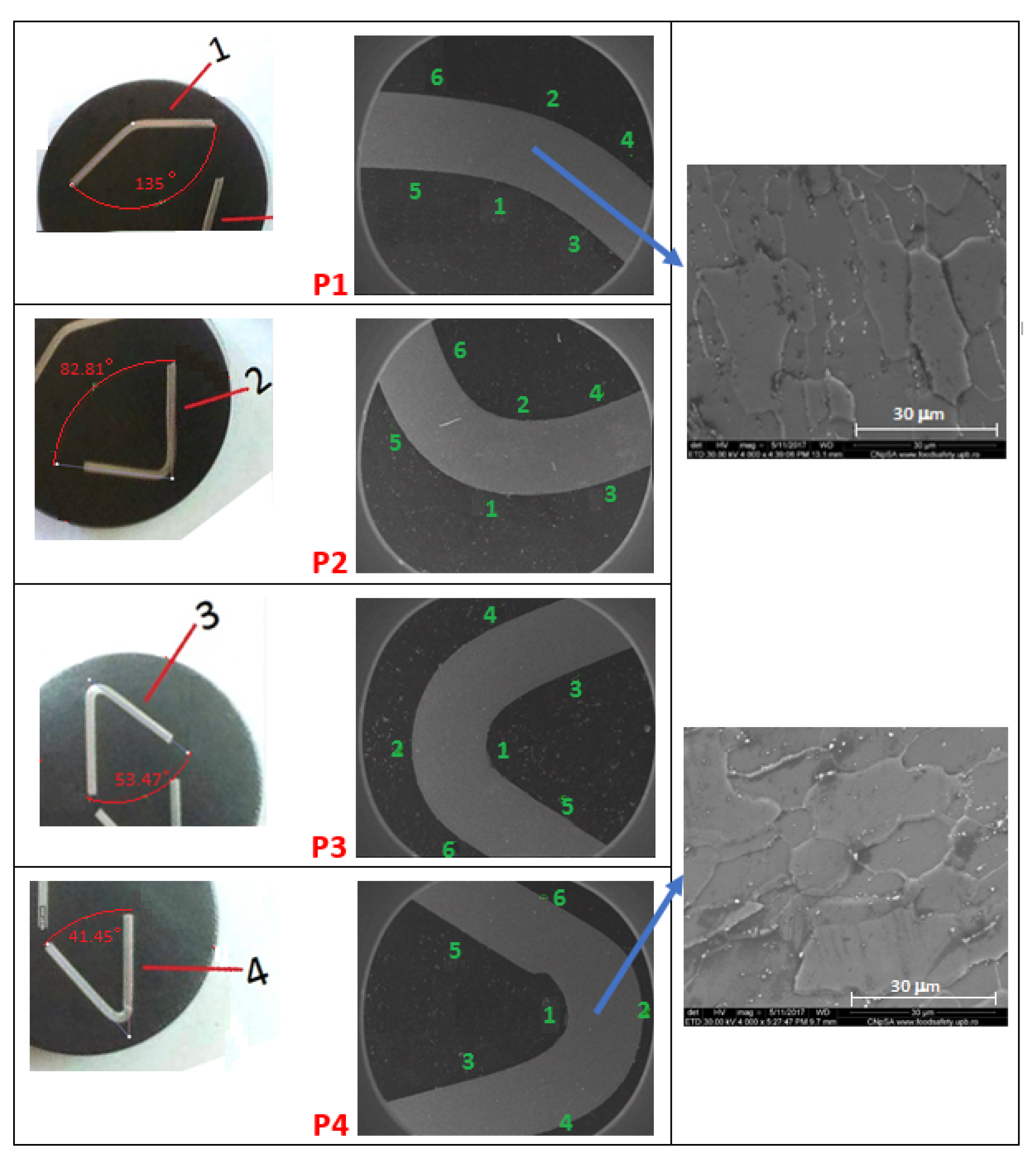
2.5.1. Analysis of the Metallic Material’s Behaviour after the CCF Process

The general aim of the investigations was to understand the complex metallic material’s real behaviour after folding. The approach was to obtain the variation in the local metallic material’s characteristics in some relevant areas of the folded element: (1) along the folding contour, (2) in the proximity of the folding contour and (3) in the mid-section of the strip (Figure 15).
Different kinds of samples were collected from a single folded element and then subjected to uniaxial tensile tests to obtain representative stress–strain curves and the flow stress profile of the metallic material in different areas of the folded element.

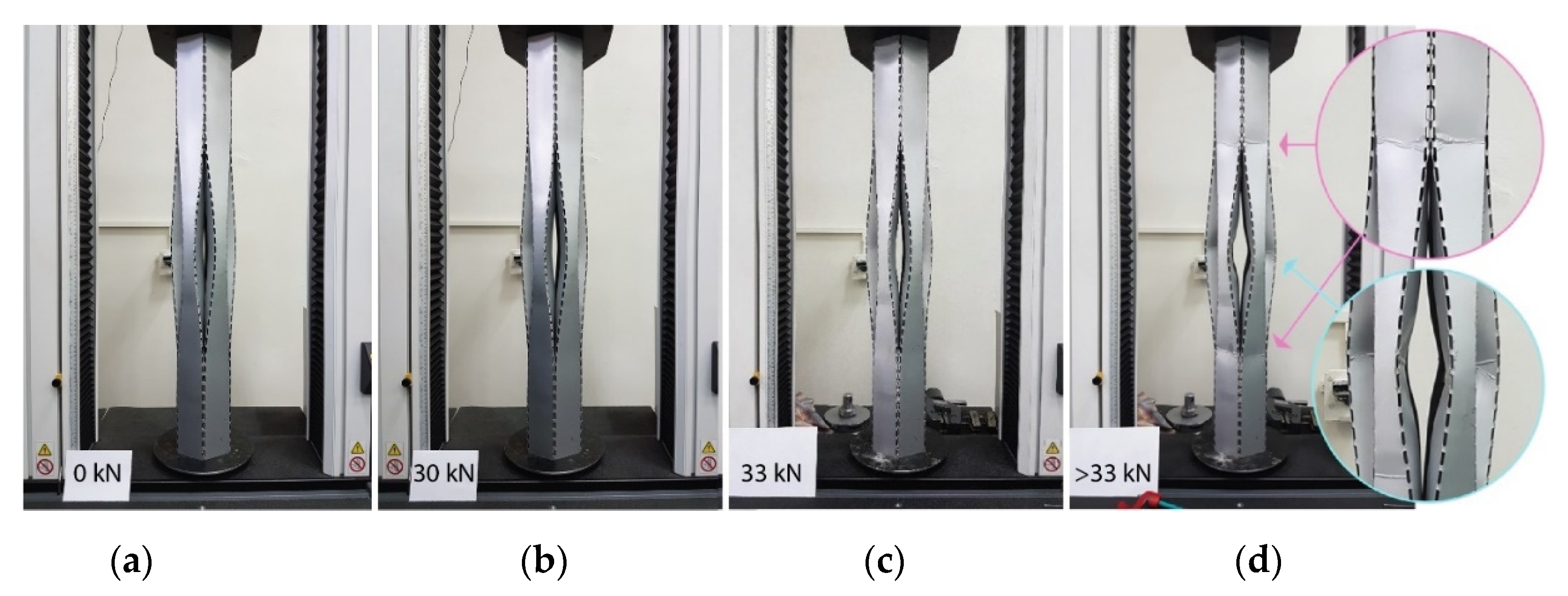
2.5.2. Mechanical and Structural Testing of the Metallic Column

The experimental model of the thin-walled metallic structure (column) was mechanically tested regarding compression using an Instron 3382 universal testing machine (SC Ro-Mega Control SRL, Romania). Thirty successive individual loading/unloading tests were performed according to the following scenario: for the first test, the total loading force was 1.0 kN; the total loading force increased for the following tests with an increment of 1.0 kN per test. The loading rate was 0.5 kN/s for all 30 individual tests. For each test, at the maximum load, additional measurements of deformed zones in the inner gaps of the column were made for the detailed evaluation of the locally deformed zones.

3. Results

3.1. Analysis of the Metallic Material’s Behavior after the CCF Process

Experimental techniques based on material science were applied to evaluate the metallic material’s deformation mechanisms and deformation components (elastic and plastic); they are here described.
The procedure for the sample selection was as follows: the planar cut-out was obtained digitally after the virtual simulation of the folding process in the Rhino environment. It was physically transferred to the metallic sheet and then the metallic sheet was curved crease folded to obtain one single element of the spatial structure (the column, which was made of six folded elements). This process was repeated many times to obtain the necessary number of constitutive elements. Samples were extracted as depicted in Figure 15 using a single folded element as a specimen. The other folded elements were used for the realization of the column assembly.
Two kinds of samples were collected from a single folded element: the first kind of samples was used to obtain data about the mechanical characteristics of the metallic material in different areas of the folded element: in the proximity of the folding contour (blue) and in the centre of the strip (red) (Figure 15a); these samples were used for the uniaxial tensile tests with the orientation marked with arrows. For the base material properties, samples from the sheet metal were separately realized. All these samples were dog-bone-shaped samples with a calibrated section/gauge length of 40 × 5 × 1 mm. The second kind of samples was collected transversally on the column longitudinal axis to analyse the variation of the folding angle along the folding paths in four sections (Figure 15a (purple) and Figure 15b).
The samples were collected using a Metkon MICRACUT 200 machine (Metkon Instruments Inc., Bursa, Turkey) with precision cutting. The samples used for the analysis of the folding angle variation were mounted in phenol conductive resin, metallographically polished and then etched for the microstructural analysis (Figure 15b and Figure 16).
The folding angles were measured using Inkscape 0.92.1. (SC Ro-Mega Control SRL, Romania) to obtain a real image of the metallic material’s local deformation features (Figure 16). Post-folding, with the increase of the folding angle, the reorientation of the material’s crystalline grains was observed (Figure 16 (right)) due to the local deformation process in the proximity of the folding line.
An INSTRON 3382 machine (SC Ro-Mega Control SRL, Romania) was used for uniaxial tensile tests to obtain representative stress–strain curves and the flow stress profile for the samples marked with red and blue (Figure 15a) and for the base metallic material properties. The tensile testing measurements were performed at a 1 mm/s crosshead speed on the testing machine, which was equipped with a 12.5 mm displacement extensometer. The samples were tensile tested along the vertical axis direction.
The mechanical properties were computed based on recoded engineering strain–stress curves; the diagrams are given in Figure 17. The following mechanical characteristics were determined from the strain–stress diagrams: yield strength—σ0.2 (MPa), ultimate tensile strength—σUTS (MPa), elongation to fracture—εf (%) and elastic modulus—E (GPa) (Table 1).

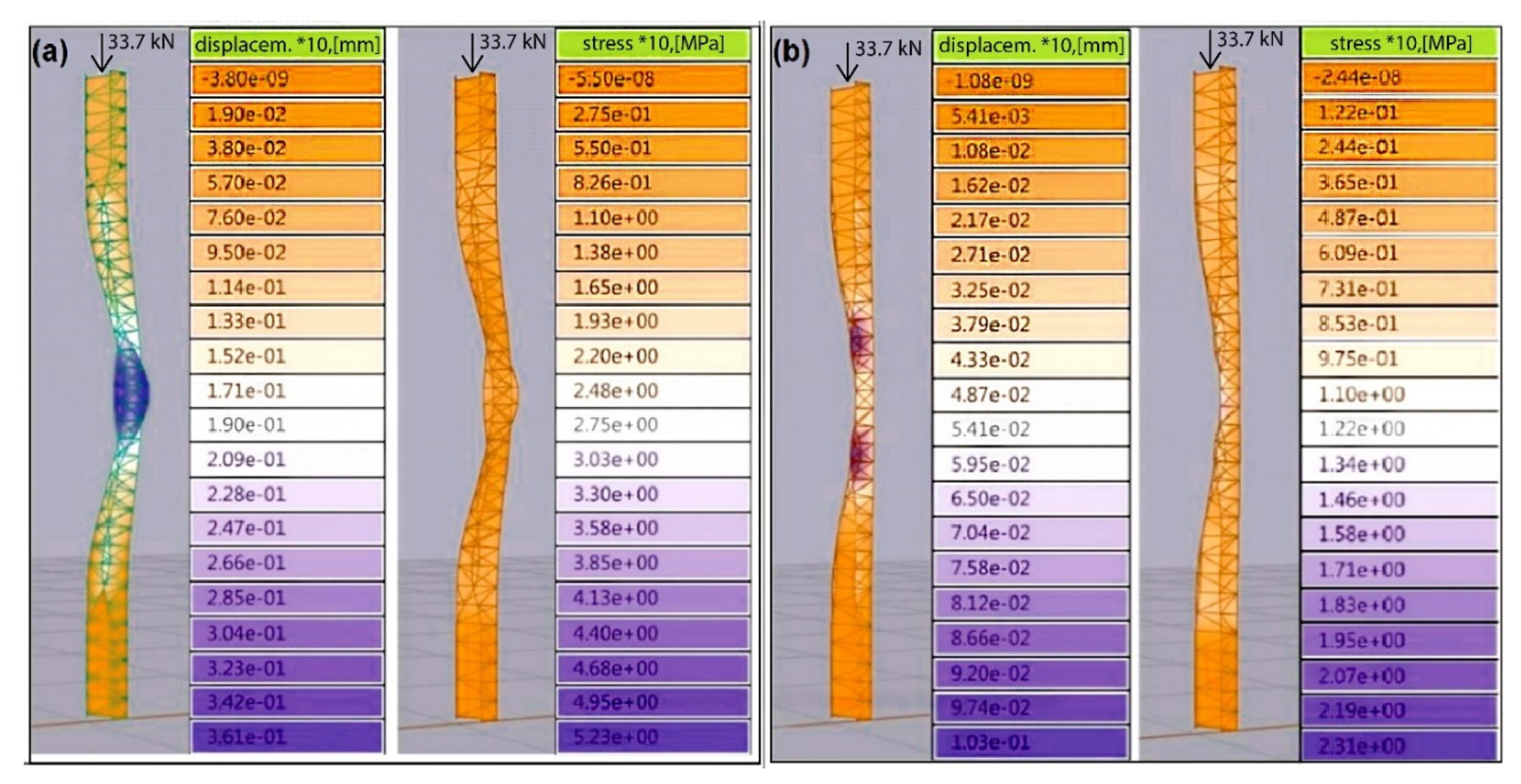
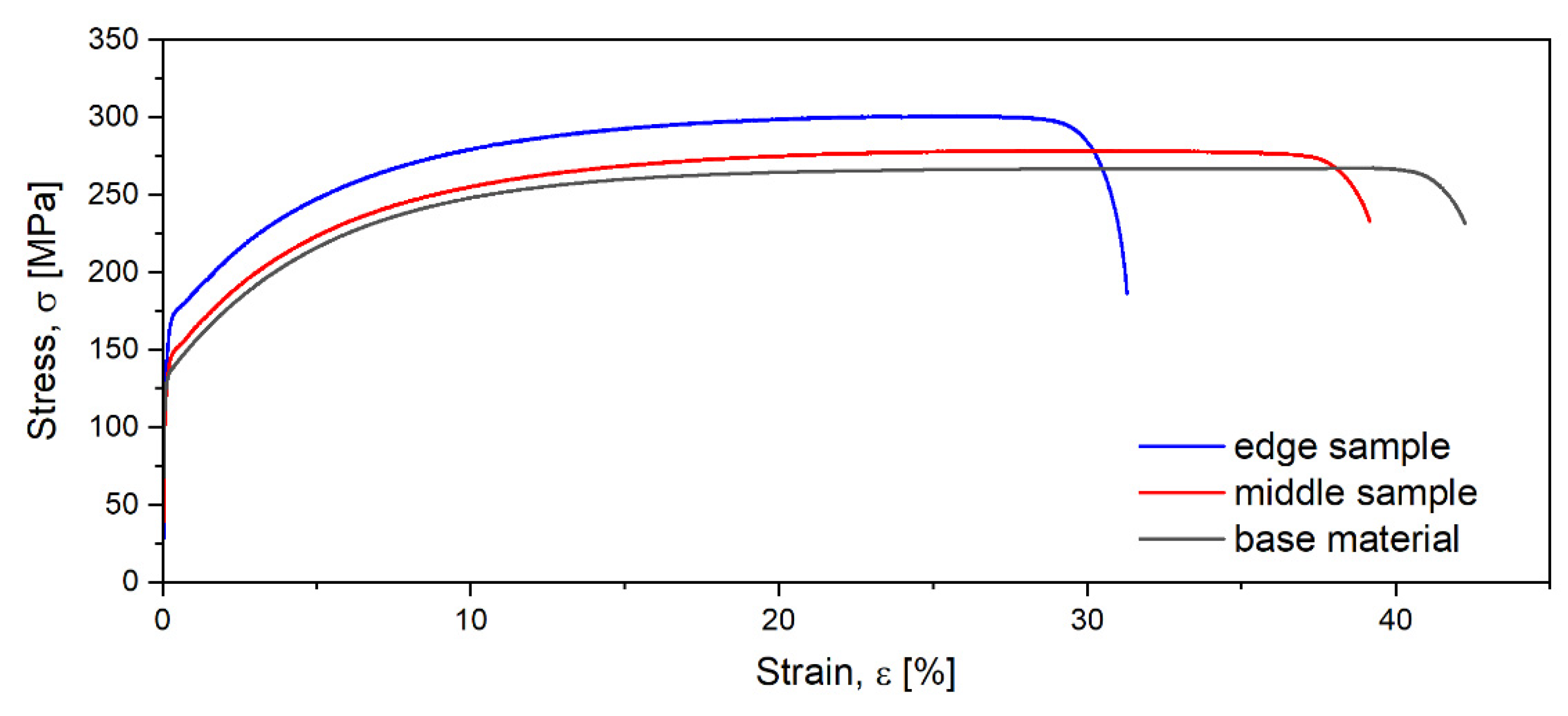
3.2. Mechanical Testing of the Metallic Column

The experimental model of the metallic column was mechanically tested for compression in the conditions presented in Section 2.5.2 (Figure 18a,b).
At the maximum load of 30 kN, the metallic column had a vertical compression of only 0.94 mm; the performing-weight-to-load-bearing ratio of the column was a good ratio of 1:64 (which can be compared with other values, for example, 1:10 in the case of other unconventional structures [50]).
A second series of mechanical tests was executed to test the experimental model to its collapse, which started with an axial force of 33 and 34 kN (Figure 18c,d).
During each of the mechanical tests, in situ measurements were made in the central/ median part of the metallic column for the deformation evaluations of the critical elastic/plastic deformed zones of the column (Figure 19a).
The measurements during the mechanical tests for the deformation evaluations of the critical zones of the metallic column were directly realized in situ during each of the 30 successive mechanical tests of the spatial structure. The experimental setup is described in the following. The median section of the spatial structure was identified on a digital representation and then it was marked directly (physically, in situ) on the column with specific makers. A deformed real image of this median section can be seen in Figure 14b. For a better illustration of the median transverse section of the column, a graphical representation (Figure 19b) was realized to show the places where the measurements were made. For one location out of six in Figure 19b, the types of measurements are marked with colours (yellow, blue, magenta). The measurements were made with an INSTRON AVE-2 non-contacting video extensometer (SC Ro-Mega Control SRL, Romania), which can measure deformation by tracking the movement of two attached markers on the specimen. A gauge length of 60 mm was used during each mechanical test for each of the 30 loading tests in each of the six zones to determine the variation of deformations, expressed in specific metrics, in the critical zones of the spatial structure as a function of the testing load applied. Insignificant differences in the behaviour between the six locations were observed during one single column test because the data acquisition showed quite similar values. The measurements’ data were acquired for all six locations for each of the 30 tests for statistical processing, which was done algorithmically based on the usual formulas to obtain the graphs in Figure 20b,c and the metrics of deformation presented in Section 4. The colour code used for the measurements (Figure 19b) and the graphs (Figure 20b,c) obtained after the processing of the experimental data is the same.
The evolution of specific parameters concerning the local deformations is presented in Figure 20b,c.

4. Discussion

4.1. Metallic Material’s Behavior after the CCF Process

The mechanical behaviour of polycrystalline metallic materials is defined by stress–strain fields, which occur as a result of external stimuli/loads and are mediated by the microstructure–mechanical properties relationship [51,52,53]. In this analysed case, the deformation-induced effects were the result of stresses and strains acting on the metallic material during and after the folding process.
A general characteristic observed from the curves in Figure 17 is the presence of a flat segment corresponding to the plastic deformation zone. The flat part of the curve indicates a consolidation in the plastic deformation regime, which caused the yield strength to be rather close to the ultimate tensile strength.
By analysing the stress–strain curves, the following observations can be highlighted: compared with the material situated in the proximity of the folding contours, the material situated in the centre of the folded element had lower σ0.2 and σUTS values, which can be explained by the lack of local plastic deformation, accompanied by strain hardening. In addition, the modulus of elasticity in the middle region had a lower value. As concerns the elongation, the obtained value for the metallic material situated in the centre of the folded element was smaller than for the metallic material situated in the proximity of the folding contour (32% compared to 40%). These variations in the metallic material mechanical characteristics were augmented for the entire folded element by the variation in the folding angle along the folding contours (Figure 15b and Figure 20c). A small value of the folding angle meant a stronger local plastic deformation with additional strain hardening; therefore, the intensity of the local plastic deformation effects varied depending on the folding angle; further investigations of this aspect will follow.
The features described above were due to complex interrelations between the stress, stress state, strain and strain rate of the folding process. Within the material, strain hardening increased the local stiffness of the sheet and the overall rigidity within the structure (the entire column).
The way in which the gradient of strain hardening and local plastic deformation variation associated with the curve folding process affects the final properties of the entire structure needs to be very well known for the final design and material selection. Each metallic material has its own deformation reaction [54,55] to mechanical stimuli, with curved folding processing being a particular one. This reaction depends mainly on the specific structural state of the metallic material, which provides certain deformation/mechanical properties. These properties have a specific variation, as it was described; algorithmic design permits the changing of many parameters, including some referring to the material’s behaviour till a good solution is reached (Figure 13b (right)). Just for the present design, due to the specific spatial form, the deformation was quite similar in the middle part of the folded element (middle sample) with the deformation of the base material, with some small differences due to the additional tension that was induced after folding.

4.2. The Mechanical Behavior of the Metallic Column during Loading

The weak zones of the design, where the structural element caved in due to folding, clearly stood out in the permanently deformed metallic column state (Figure 18c,d). Additionally, the post-folding simulations could predict where the weak spots were on the design by noting that the metallic material’s behaviour was totally different during and after folding compared with before folding. The weak spots identified in Figure 12 after folding were confirmed by testing the experimental model to its collapse (Figure 18d).
By measuring the deformations in the central zone of the metallic column (Figure 19a), at each of the 30 steps of the mechanical testing, the following behaviour was observed: at the maximum load, the inner gap of the column increased by 94%, while the distance between the fold lines had a minute enlargement of 3.7% (Figure 20b); the angle variation, in absolute values, is presented in Figure 20c. At the fold lines, the angle presented a maximum variation (at the centre) of 6.85 degrees or 0.12 rad (Figure 20). Although crinkles started appearing close to the 30 kN load, after the final test, the plastic deformations were very small, 8.1% for the inner gap, which was practically negligible, and 0.37% between the fold lines; therefore, the column shape was practically unaltered after the loading. The predominant elastic behaviour of the column shows the structure’s capacity to store energy under a load and release it when unloaded (Figure 18b). Finally, the good load ratio of 538 kgf/kg demonstrates the efficiency of design, which was due to the intrinsic properties of the metallic material.

4.3. Design Modifications and Prospects

Considering the results of the build and tested sheet of the metal experimental model, the next step was to identify possible design enhancement directions. There are several categories that can be explored, and they are mentioned below.
The tendency of the composing elements of the metallic column to buckle needs to be mediated with the architectural aspiration to have a sinuous column. There are some specific weak areas that were revealed in the mechanical tests. These can be modified through different methods.
One approach is to use a punching press to emboss the material in the problematic regions to locally harden it. Another approach would be to use edge stiffeners (Figure 21a), which is a common way to improve the structural properties of cold-formed linear profiles [56]. A linear stiffening of the naked edges of an element was tested but was found to hinder to a great extent the willingness of the material to adopt the curved shape when the planar development is folded. Another option is to use pairs of U-shaped elements so that the profiles are closed (Figure 21b). These elements could also be used as beams or to build semi-transparent walls. The deformations would decrease in size and the load-bearing capacity of the column would increase; however, the weight would become almost double.
An alternative to this approach is to connect the six elements into one, filling the gaps with material. The column can be manufactured out of one continuous strip that has only one connection line (albeit not necessarily convenient from a fabrication point of view at a 1:1 scale). The weight of the column would be the same as in the model analysed in this study, but the amount of deformation would significantly decrease. The disadvantage is there are no distinctive elements that form the column and the gaps disappear (Figure 21c (right)). However, new folding lines appear, which do offer some transparency due to the whole elongated pattern.

5. Conclusions

A thin-walled metallic structure (column) of a free-form type, which was algorithmically designed based on CCF, was realized and mechanically tested.
A new method for the (algorithmic) curved folding digital design was proposed; the developed algorithm digitally implemented resistance to folding (a material property) using specific instruments and their associated mathematical functions; resistance to bending was implemented into the algorithm as a feature of the metallic material’s behaviour; furthermore, virtual banks (grips) to fold the flat sheet into place were used to control the lateral strips’ tendency to splay. A post-folding analysis was realized; the purpose was not to reproduce the folding process but to identify the weak spots of the ensemble.
The developed planar cut-out was algorithmically generated (using Grasshopper and Kangaroo) to easily modify the column’s proportions and generate variations of fold paths; it was then physically realized from the metallic material using different individual perforation patterns along the fold paths. The effects of the elongated perforations on the test results were discussed.
The experimental model of the column, consisting of six metallic elements that were folded following curved paths, was realized using 1 mm thick Fe360 (CEN-EN)/A283 (USA ASTM, ArcelorMittal Galati, Romania) sheet metal as the metallic material. A punch press was used to define the folding trajectories; the folding process was realized using a manual press brake. The metallic material was used in both plastic and elastic regimes. It was partially plastically deformed when folded into its three-dimensional shape and elastically deformed when tested as an ensemble under load. When unloading, the residual plastic deformations were negligible before the structure collapse.
The specific material behaviour that was augmented by the proposed curved folded design allowed for obtaining a light structural element with a good load capacity ratio of 538 kgf/kg.
After folding, the analysis of the metallic material behaviour was realized at two scales: locally, in different regions of the folded elements, and globally, for the entire structure/column. The evolution of the mechanical characteristics of the metallic material in different regions of the folded element showed the variations of local mechanical characteristics due to the hardening process acting at a microstructural scale. Furthermore, these processes developed with different intensities due to the variations in folding angle along the folding contour. The data were useful for understanding the complex behaviour of a metallic material when it is processed using folding.
This study highlights the importance of the connections between the design constraints with the specific metallic material’s behaviour in a CCF process.

Supplementary Materials

The following are available online at https://www.mdpi.com/article/10.3390/pr9071110/s1.

Author Contributions

Conceptualization: D.R.; methodology and software: V.A.R.; validation: V.D.C. and V.A.R.; formal analysis: A.N.; investigation: N.S., I.C., E.M.C., L.M. and C.T.-R.; data curation: V.D.C.; writing—original draft preparation: D.R.; writing—review and editing: I.V.B.; writing—editing: V.A.R. and A.N.; visualization: D.R.; supervision: V.A.R. All authors have read and agreed to the published version of the manuscript.

Funding

This research was funded by the Romanian National Authority for Scientific Research, CCCDI—UEFISCDI, Project PCCA, grant no. 316/2014-2018 and PN-III-P2-2.1-PED-2019-4624/grant no. 468PED/2020. The statements made herein are solely the responsibility of the authors.

Data Availability Statement

The data presented in this study are available on request from the corresponding author.

Acknowledgments

The authors acknowledge the assistance of CCCDI–UEFISCDI and facilities and the scientific and technical assistance of the staff within the Materials Science and Engineering Faculty, University POLITEHNICA of Bucharest.

Conflicts of Interest

The authors declare no conflict of interest.

References

  1. Flory, S.; Nagai, Y.; Isvoranu, F.; Pottmann, H.; Wallner, J. Ruled free forms. In Advances in Architectural Geometry 2012; Hanssen, L.M., Ed.; Springer: Berlin/Heidelberg, Germany, 2013; pp. 57–66. [Google Scholar]
  2. Wong, J.F. The text of free-form architecture: Qualitative study of the discourse of four architects. Des. Stud. 2010, 31, 237–267. [Google Scholar] [CrossRef]
  3. Liu, J.; Fan, X.; Wen, G.; Qing, Q.; Wang, H.; Zhao, G. A Novel Design Framework for Structures/Materials with Enhanced Mechanical Performance. Materials 2018, 11, 567. [Google Scholar] [CrossRef] [PubMed] [Green Version]
  4. Luck, R. Kinds of seeing and spatial reasoning: Examining user participation at an architectural design event. Design Studies 2012, 33, 557–588. [Google Scholar] [CrossRef]
  5. Bullock, G.N.; Denham, M.J.; Parmee, I.C.; Wade, J.G. Developments in the use of the genetic algorithm in engineering design. Des. Stud. 1995, 16, 507–524. [Google Scholar] [CrossRef]
  6. Bates-Brkljac, N. Assessing perceived credibility of traditional and computer generated architectural representations. Des. Stud. 2009, 30, 415–437. [Google Scholar] [CrossRef]
  7. Kaveh, A.; Ghazaan, M.I. Meta-Heuristic Algorithms for Optimal Design of Real-Size Structures; Springer: Berlin/Heidelberg, Germany, 2018. [Google Scholar]
  8. Wang, X.; Zhang, Q.; Qin, X.; Sun, Y. An efficient discrete optimization algorithm for performance-based design optimization of steel frames. Adv. Struct. Eng. 2020, 23, 411–423. [Google Scholar] [CrossRef]
  9. Hybs, I.; Gero, J.S. An evolutionary process model of design. Des. Stud. 1992, 13, 273–290. [Google Scholar] [CrossRef]
  10. Singh, V.; Gu, N. Towards an integrated generative design framework. Des. Stud. 2012, 33, 185–207. [Google Scholar] [CrossRef]
  11. Vaissier, B.; Pernot, J.P.; Chougrani, L.; Veron, P. Parametric design of graded truss lattice structures for enhanced thermal dissipation. Comput. Aided Des. 2019, 115, 1–12. [Google Scholar] [CrossRef]
  12. Chahardoli, S.; Alavi Nia, A.; Asadi, M. Parametric investigation of the mechanical behavior of expanding-folding absorbers and their implementation in sandwich panels core. Thin-Walled Struct. 2019, 137, 53–66. [Google Scholar] [CrossRef]
  13. Talaslioglu, T. Optimal design of steel skeletal structures using the enhanced genetic algorithm methodology. Front. Struct. Civ. Eng. 2019, 13, 863–889. [Google Scholar] [CrossRef]
  14. Bello-Garcia, A.; Coz Diaz, J.J.; Suarez, F.; Prendes Gero, M.B. Optimization of steel structures with one genetic algorithm according to three international building codes. Rev. Constr. 2018, 17, 47–59. [Google Scholar] [CrossRef] [Green Version]
  15. Ahlquist, S.; Kampowski, T.; Torghabehi, O.O.; Menges, A.; Speck, T. Development of a digital framework for the computation of complex material and morphological behavior of biological and technological systems. Comput. Aided Des. 2015, 60, 84–104. [Google Scholar] [CrossRef]
  16. Rezazadeh, F.; Mirghaderi, R.; Hosseini, A.; Talatahari, S. Optimum energy-based design of BRB frames using nonlinear response history analysis. Struct. Multidiscip. Optim. 2017, 57, 1005–1019. [Google Scholar] [CrossRef]
  17. Mansouri, I.; Soori, S.; Amraie, H.; Hu, J.; Shahbazi, S. Performance based design optimum of CBFs using bee colony algorithm. Steel Compos. Struct. 2018, 27, 613–622. [Google Scholar]
  18. Mundilova, K. On mathematical folding of curved crease origami: Sliding developables and parametrizations of folds into cylinders and cones. Comput. Aided Des. 2019, 115, 34–41. [Google Scholar] [CrossRef]
  19. Zhu, L.; Igarashi, T.; Mitani, J. Soft folding. Comput. Graph. Forum 2013, 32, 167–176. [Google Scholar] [CrossRef]
  20. Lebee, A. From Folds to Structures-a Review. Int. J. Space Struct. 2015, 30, 55–74. [Google Scholar] [CrossRef] [Green Version]
  21. Kilian, M.; Flory, S.; Chen, Z.; Mitra, N.J.; Sheffer, A.; Pottmann, H. Curved folding. ACM Trans. Graph. 2008, 27, 1–9. [Google Scholar] [CrossRef] [Green Version]
  22. Wang, F.; Gong, H.; Chen, X.; Chen, C.Q. Folding to Curved Surfaces: A Generalized Design Method and Mechanics of Origami-based Cylindrical Structures, September 2016, Scientific Reports 6:33312. Available online: https://www.nature.com/articles/srep33312 (accessed on 13 January 2021).
  23. Rabinovich, M.; Hoffmann, T.; Sorkine-Hornung, O. Modeling Curved Folding with Freeform Deformations, ACM SIGGRAPH ASIA 2019. In Proceedings of the 12th SIGGRAPH Conference and Exhibition on Computer Graphics and Interactive Techniques in Asia, BCEC Brisbane, Australia, 17–20 November 2019; Available online: https://igl.ethz.ch/publications/igl-bibtex.php#Rabinovich:Curvedfolds:2019 (accessed on 24 January 2020).
  24. Bhooshan, S.; Bhooshan, V.; ElSayed, M.; Shepherd, P. Applying dynamic relaxation techniques to form-find and manufacture curve-crease folded panels. Simul. Trans. Soc. Modeling Simul. Int. 2015, 91, 773–786. [Google Scholar] [CrossRef] [Green Version]
  25. Gattas, M.J.; You, Z. Miura-base rigid origami: Parametrizations of curved-crease geometries. J. Mech. Des. 2014, 136, 121404. [Google Scholar] [CrossRef]
  26. Mitani, J.; Igarashi, T. Interactive Design of Planar Curved Folding by Reflection. Pac. Graph. 2011, 77–81. [Google Scholar] [CrossRef]
  27. Huffman, D.A. Curvature and Creases: A Primer on Paper. IEEE Trans. Comput. 1976, 10, 1010–1019. [Google Scholar] [CrossRef]
  28. Photo. Available online: www.flickr.com/photos/53416300@N00/15153304523 (accessed on 10 May 2020).
  29. Demaine, E.D.; Demaine, M.L.; Koschitz, D.; Tachi, T. Curved Crease Folding a Review on Art, Design and Mathematics, Personal Communication. Available online: http://martindemaine.org/papers/CurvedCrease_IASS2011/paper.pdf (accessed on 10 July 2020).
  30. Wang, S.; Xia, Y.; Wang, R.; You, L.; Zhang, J. Optimal NURBS conversion of PDE surface-represented high-speed train heads. Optim. Eng. 2019, 20, 907–928. [Google Scholar] [CrossRef] [Green Version]
  31. Miyashita, S.; DiDio, I.; Ananthabothla, I.; An, B.; Sung, C.; Arabagi, S.; Rus, D. Folding Angle Regulation by Curved Crease Design for Self-Assembling Origami Propellers. J. Mech. Robot. 2015, 7, 2. [Google Scholar] [CrossRef] [Green Version]
  32. Lee, T.U.; You, Z.; Gattas, J.M. Elastica surface generation of curved-crease origami. Int. J. Sol. Str. 2018, 136, 13–27. [Google Scholar] [CrossRef]
  33. Vergauwen, L.A.; De Laet, N. De Temmerman, Computational modelling methods for pliable structures based on curved-line folding. Comput. Aided Des. 2017, 83, 51–63. [Google Scholar] [CrossRef]
  34. Available online: https://www.robofold.com/make/process/process-4/ (accessed on 17 December 2019).
  35. Gholizadeh, S.; Fattahi, F. Damage-controlled performance-based design optimization of steel moment frames. Struct. Des. Tall Spec. Build. 2018, 27, e1498. [Google Scholar] [CrossRef]
  36. Eversmann, P.; Ihde, A.; Ehret, A. Curved-folding of thin aluminium plates: Towards structural multi-panel shells. In Proceedings of the IASS Annual Symposia, Hamburg, Germany, 25–27 September 2017. [Google Scholar]
  37. Garrett, D.; You, Z.; Gattas, J.M. Curved crease tube structures as an energy absorbing crash box. In Proceedings of the ASME 2016 International Design Engineering Technical Conferences and Computers and Information in Engineering Conference, Charlotte, NC, USA, 21–24 August 2016; American Society of Mechanical Engineers: New York, NY, USA, 2016. [Google Scholar]
  38. Raducanu, V.A.; Cojocaru, V.D.; Raducanu, D. Structural architectural elements made of curved folded sheet metal. In Proceedings of the 34th Annual eCAADe Conference, Oulu, Finland, 22–26 August 2016; Volume 2, pp. 409–416. [Google Scholar]
  39. Nocivin, A.; Raducanu, D.; Raducanu, V.A.; Trisca-Rusu, C.; Moager Poladian, V.; Moldovan, L.; Simionescu, V.; Cinca, I.; Cojocaru, V.D. An Experimental Study for Applying Generative Design to fabricate a light Metallic Structural Element. U.P.B. Sci. Bull. Ser. B 2016, 78, 155–168. [Google Scholar]
  40. Raducanu, V.A.; Moldovan, L.; Raducanu, D.; MAngelescu, L.; Cinca, I.; Cojocaru, V.D.; Nocivin, A.; Șerban, N. Parametric Design and Structural Performances of a Light Metallic Structure. U.P.B. Sci. Bull. Ser. B 2017, 79, 97–102. [Google Scholar]
  41. Raducanu, V.A.; Cojocaru, V.D.; Raducanu, D.; Moldovan, L. Curved folded sheet metal structural columns (Poster presentation). In Proceedings of the Advances in Architectural Geometry-AAG2016 Conference, Zurich, Switzerland, 9–13 September 2016. [Google Scholar]
  42. Tachi, T.; Epps, G. Designing One-DOF Mechanisms for Architecture by Rationalizing Curved Folding. In Proceedings of the International Symposium on Algorithmic Design for Architecture and Urban Design, Tokyo, Japan, 14–16 March 2011. [Google Scholar]
  43. Miura, K. Proposition of Pseudo-Cylindrical Concave Polyhedral Shells; Institute of Space and Aeronautical Science, University of Tokyo: Tokyo, Japan, 1969. [Google Scholar]
  44. Khan, S.; Awan, M.J. A generative design technique for exploring shape variations. Adv. Eng. Inform. 2018, 38, 712–724. [Google Scholar] [CrossRef] [Green Version]
  45. Kergosien, Y.; Gotoda, H.; Kunii, T. Bending and Creasing Virtual Paper. IEEE Comput. Graph. Appl. 1994, 14, 40–48. [Google Scholar] [CrossRef]
  46. Available online: www.tsg.ne.jp/TT/software (accessed on 7 November 2019).
  47. Narain, R.; Pfaff James, T.; O’Brien, F. Folding and Crumpling Adaptive Sheets. ACM Trans. Graph. 2013, 32, 51. [Google Scholar] [CrossRef]
  48. Available online: https://simonschleicher.wordpress.com/2016/09/14/paper-at-aag2016 (accessed on 21 October 2016).
  49. Available online: www.karamba3d.com (accessed on 22 November 2019).
  50. Available online: https://www.architonic.com/en/project/oskar-zieta-fidu-bridge/5101416 (accessed on 12 February 2021).
  51. Cojocaru, V.D.; Raducanu, D.; Gloriant, T.; Gordin, D.M.; Cinca, I. Effects of cold-rolling deformation on texture evolution and mechanical properties of Ti-29Nb-9Ta-10Zr alloy. Mater. Sci. Eng. A 2013, 586, 1–10. [Google Scholar] [CrossRef] [Green Version]
  52. Mahamood, R.M.; Akinlabi, E.T. Functionally Graded Material: An Overview. In Proceedings of the World Congress on Engineering, London, UK, 4–6 July 2012; Volume III. [Google Scholar]
  53. Chahardoli, S.; Alavi Nia, A. Investigation of mechanical behavior of energy absorbers in expansion and folding modes under axial quasi-static loading in both experimental and numerical methods. Thin-Walled Struct. 2017, 120, 319–332. [Google Scholar] [CrossRef]
  54. Cojocaru, V.D.; Raducanu, D.; Gordin, D.M.; Cinca, I. Texture in ultra-strength Ti-25Ta-25Nb alloy strips. J. Alloy. Comp. 2013, 576, 170–176. [Google Scholar] [CrossRef]
  55. Oxman, R. Informed tectonics in material-based design. Des. Stud. 2012, 33, 427–455. [Google Scholar] [CrossRef]
  56. Yu, W.W.; LaBoube, R.A. Cold-Formed Steel Design, 4th ed.; John Wiley & Sons: Hoboken, NJ, USA, 2010; ISBN 978-0-470-91976-7. [Google Scholar]
Figure 1. (a) Curved crease folding through a plane reflection [27]; (b) curved folded model resulted through multiple sectioning and reflection of a cone [28].
Processes 09 01110 g001
Figure 2. (a) Model studies for the curved folded column design families—frontal and top view; (b) design family described in this paper—frontal and top view.
Processes 09 01110 g002
Figure 3. (a) The planar development and the reinterpreted planar development as a rigid origami pattern; (b) finding the ruling lines of the paper model.
Processes 09 01110 g003
Figure 4. The same paper model presenting different curvatures in different positions.
Processes 09 01110 g004
Figure 5. Digital folding simulation for planar development.
Processes 09 01110 g005
Figure 6. Flow diagram of the algorithm developed for the planar development (part of the general algorithm.
Processes 09 01110 g006
Figure 7. (a) Uniform angle folding using mirror reflecting rulings; (b) non-uniform folding (generic) [24].
Processes 09 01110 g007
Figure 8. The end parts of the strip did not remain collinear when folding in both: (a) the paper mock-up and (b) the digital simulation.
Processes 09 01110 g008
Figure 9. The algorithm for the digital CCF simulation.
Processes 09 01110 g009
Figure 10. Development of a personalized planar quad algorithm: (a) individual folded strips; (b) strips splaying; (c) virtual banks (grips) used to fold the flat sheet/allow for planar development.
Processes 09 01110 g010
Figure 11. Digitally determining the intersection curve of the two folded side strips.
Processes 09 01110 g011
Figure 12. (a) Displacement and von Mises stress [49] analysis for the “non-welded” model; (b) the same tests under the same load for the “welded” model.
Processes 09 01110 g012
Figure 13. The results after the curved folding process: (a) circular perforations used for the folding contour—planar development (left), folded element (right); (b) elongated perforations used for the folding contour—perforation distribution (left), folded element (right).
Processes 09 01110 g013
Figure 14. (a) The experimental model of the thin-walled metallic structure (column); elongated perforations for the folding contour were used for the planar cut-out before the crease-curved-folding process. (b) Inside view from the top of the metallic column.
Processes 09 01110 g014
Figure 15. (a) Sample collection for the uniaxial tensile tests and sample collection for the folding angle variation measurements; (b) samples showing the folding angle variation along the folding contour for the four sections selected.
Processes 09 01110 g015
Figure 16. The four samples with different folding angles (135° for P1, 82.81° for P2, 53.47° for P3 and 41.45° for P4): left—folding angles measurements; middle—embedded cross-sections (×60); right—microstructural view detail indicated by the coloured arrow (×4000) for samples P1 and P2.
Processes 09 01110 g016
Figure 17. Stress–strain diagrams for the base material (black curve), the material in the proximity of the folding contour (edge sample—blue curve) and in the centre of the folded element (middle sample—red curve).
Processes 09 01110 g017
Figure 18. Deformations during the compression tests: (a) before loading; (b) at maximum load; (c) the ultimate state before the metallic column started to collapse; (d) metallic column showing permanent damage in 3 key areas.
Processes 09 01110 g018
Figure 19. The measurements during the mechanical tests: (a) in situ measurements; (b) graphical representation of the median transverse section of the spatial structure.
Processes 09 01110 g019
Figure 20. Specific parameters concerning the global/local deformations: (a) the inner gap width and the distance between the fold lines; (b) the displacements under a load; (c) the folding angle variation.
Processes 09 01110 g020
Figure 21. (a) Edge stiffeners used in conventional cold-formed profiles [56]; (b) pairs of U-shaped profiles could be used in rows to build semi-transparent walls; (c) column model with no gaps.
Processes 09 01110 g021
Table 1. Local mechanical characteristics of the metallic material before and after folding.
Mechanical CharacteristicBase MaterialEdge SampleMiddle Sample
Yield strength—σ0.2 (MPa)165.3177.5146.5
Ultimate tensile strength—σUTS (MPa)267.5300.9278.8
Elongation to fracture—εf (%)424032
Elastic modulus—E (GPa)141.3143.5138.4
Publisher’s Note: MDPI stays neutral with regard to jurisdictional claims in published maps and institutional affiliations.

