Review

Microbial Fuel Cell Technology—A Critical Review on Scale-Up Issues

1
Department of Chemical and Environmental Engineering, University of Nottingham Malaysia, Semenyih 43500, Selangor, Malaysia
2
Department of Chemical Engineering and Biotechnology, National Taipei University of Technology, Taipei 106, Taiwan
3
Green Energy and Environment Institute, Industrial Technology Research Institute, Hsinchu 31040, Taiwan
4
Faculty of Bioengineering and Technology, Universiti Malaysia Kelantan, Jeli Campus, Jeli 17600, Kelantan, Malaysia
5
Department of Fundamental and Applied Sciences, HICoE-Centre for Biofuel and Biochemical Research, Institute of Self-Sustainable Building, Universiti Teknologi PETRONAS, Seri Iskandar 32610, Perak, Malaysia
6
Green Energy Technology Research Center and Department of Materials Engineering, Kun Shan University, Tainan 710, Taiwan
*
Authors to whom correspondence should be addressed.
Processes 2021, 9(6), 985; https://doi.org/10.3390/pr9060985
Submission received: 20 April 2021 / Revised: 30 April 2021 / Accepted: 3 May 2021 / Published: 3 June 2021

Abstract

:
Microbial fuel cell (MFC) technology has attracted a great amount of attention due to its potential for organic and inorganic waste treatment concomitant with power generation. It is thus seen as a clean energy alternative. Modifications and innovations have been conducted on standalone and hybrid/coupled MFC systems to improve the power output to meet the end goal, namely, commercialization and implementation into existing wastewater treatment plants. As the energy generated is inversely proportional to the size of the reactor, the stacking method has been proven to boost the power output from MFC. In recent years, stacked or scale-up MFCs have also been used as a power source to provide off-grid energy, as well as for in situ assessments. These scale-up studies, however, encountered various challenges, such as cell voltage reversal. This review paper explores recent scale-up studies, identifies trends and challenges, and provides a framework for current and future research.

1. Introduction

Biomass energy and wood fueled the world economy for thousands of years before the industrial revolution [1]. Since then, fossil fuels have replaced biomass for nearly a century. However, fossil fuel depletion and carbon dioxide emissions posed a future challenge to sustain the demands for electricity and the environment [2]. Policymakers in many countries have amended energy independence and climate change policies to promote the development of renewable energy technology [3]. With the exponential growth of the world population, the demands for food and energy have increased drastically in recent years, putting unprecedented pressure on the food chain system, as well as the world’s ecosystem [4].
Microbial fuel cell (MFC) technology is among the renewable and sustainable technologies that consume organic and inorganic waste to generate electricity, and it has been constantly developing in recent decades [5,6,7,8,9]. MFCs utilize the metabolic energy of bacteria to produce electricity, whilst the bacteria act as a biocatalyst to oxidize organic and inorganic matters and produce electrons and protons. The protons are transported to the cathode chamber via the proton exchange membrane (PEM), and the electrons are transferred through an external circuit to a terminal electron acceptor in the cathode chamber, thereby generating power (Figure 1).
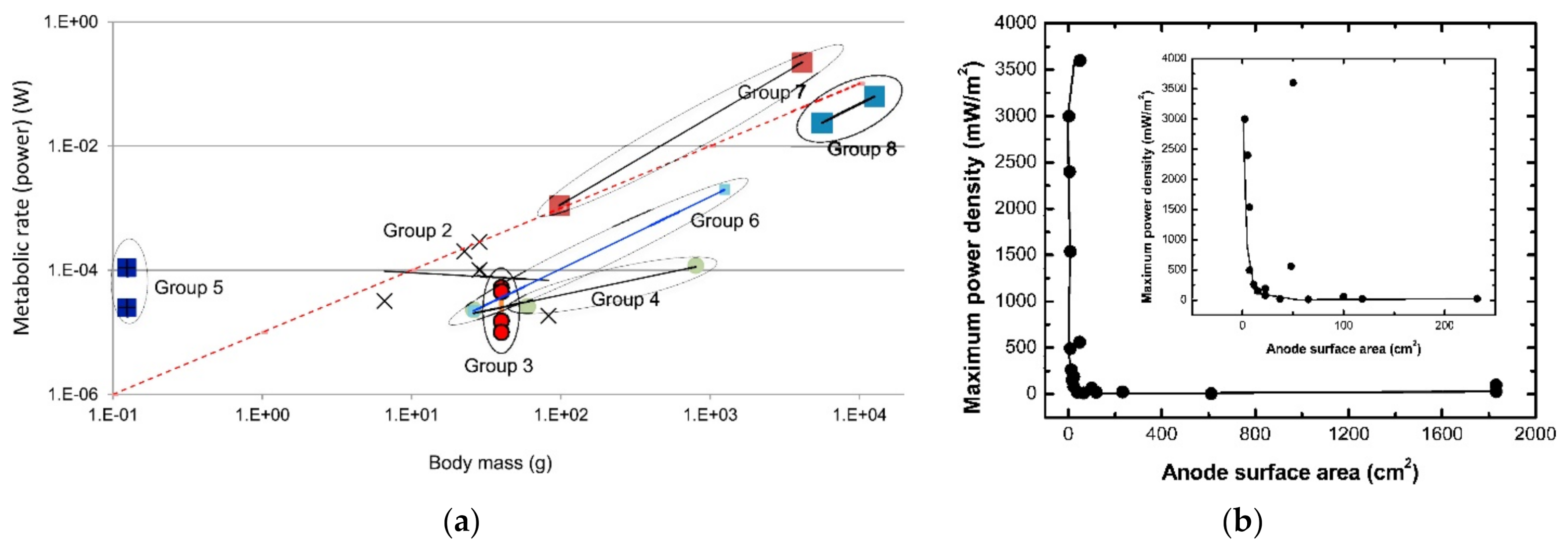
MFC technology has the potential to extract energy from various organic and inorganic substrates to generate a surplus of electricity for plant operation. The technology was used and tested mainly for municipal wastewaters [10] and various industrial effluents [11], such as protein-rich wastewater [12,13] and starch processing wastewater [14]. It was also used as a power source to provide off-grid energy for remote system charging [15,16,17]. The real applications would require the scale up of the MFC reactors. Various approaches were reported, for instance, modifications on the electrode design and materials [16,18,19], membrane design or use of a membrane-less system [20,21], and the use of the stacking method via series and/or parallel connections of multiple MFC units [22,23,24,25,26]. Allometric analysis conducted by Greenman and Ieropoulos [27] suggested that a stacked microbial fuel cell has the greatest potential for practical application, as increasing the size of a microbial fuel cell system by stacking individual units would result in a linear or slightly super-linear increase in power output (Figure 2a). Therefore, in order to achieve higher power output, the authors recommended to make MFCs as small as possible whilst maintaining a high supply of fuel (e.g., wastewater), and optimizing the number of MFC units for efficient stacks [27]. Gajda et al. [28] also identified that miniaturization and multiplicity via modularity is the future trend, in addition to system architecture and longevity studies and improvements.
Scale-up MFCs, however, are found to face several limitations and challenges, for instance, high capital and operational costs [29,30], low power densities [5], operational fouling of electrode and membrane [31] and voltage and current reversal problems in stacked MFCs [32]. With regard to the sustainable potentials of MFCs, this paper reviews the recent scale-up MFC systems and subsequently identifies trends and associated challenges, lastly proposing a framework for current and future research studies.

2. Scale up

The real voltage output is affected by two major factors—the overall potentials of the anode and cathode, and the ohmic loss. The former is attributed to three basic losses, which are activation, bacterial metabolism and mass transport [7,33]. Therefore, in scaling up, the size of an individual microbial fuel cell is inversely proportional to the power density produced [6,27]. As shown in Figure 2b, the increase in the current-limiting anodic area drastically reduced the power density generated, which could be explained by the increased biofilm deposits, causing an edge effect and an increase in internal resistance [5,34]. As internal resistance (ohmic overpotential) increases, the flow of electrons between the electrodes becomes restricted, as does the movement of ions between the chambers and in the electrolyte. Apart from internal resistance, mass transfer losses generally occur due to the low diffusivity within the chamber which causes reactant depletion or product accumulation. Table 1 shows the research conducted on the scale up of MFCs in the last five years. Scale-up approaches in recent years can generally be categorized into three major areas—MFC architecture, electrode modification, and application based.

2.1. MFC Architecture

From the summary of the literature in Table 1, for scale-up reactors, generally, there are two types—one-unit with single/multiple electrodes, and stacked MFCs. Despite differences in the design, type or number of electrodes used, both single-chamber and double-chamber MFCs (SCMFCs and DCMFCs, respectively) are the popular options for scale-up reactors. The largest MFC is the movable MFC system consisting of a primary clarifier, a DCMFC and a secondary clarifier, with a total size of 1.5 m3 [21]. This movable system, consisting of 336 MFC units, was able to achieve up to 91% of chemical oxygen demand (COD) removal, 64% of total nitrogen removal and 91% of ammonium nitrogen removal when treating primary effluent, generating 0.4 W/m3 of maximum power density with a hydraulic retention time (HRT) of 5 h. This system was designed to be easily stacked to an existing wastewater tank due to its plug-in architecture.
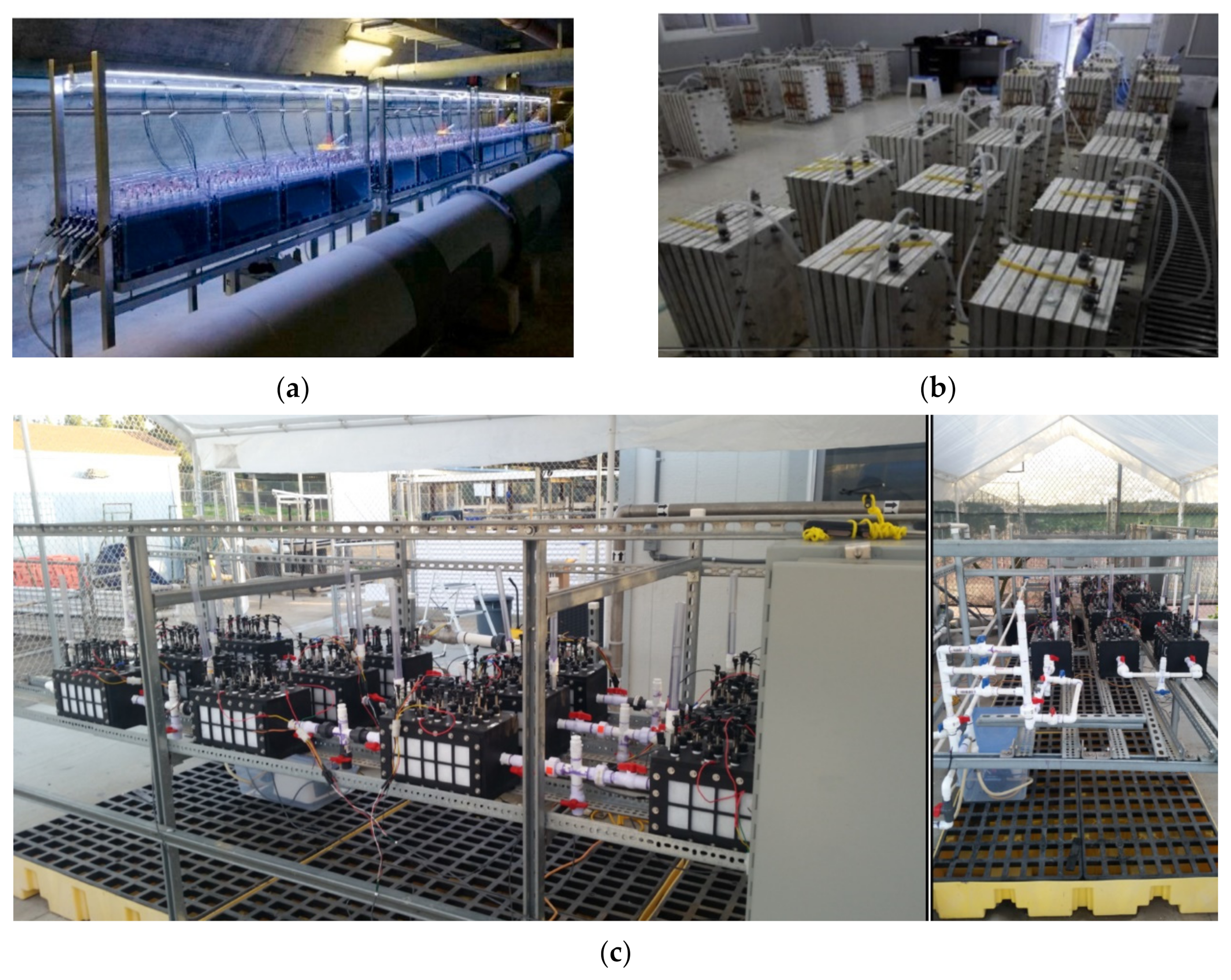
Another recent large-scale MFC is the stretched DCMFC of 1000 L consisting of 64 units developed by Blatter et al. [35]. This MFC, which was installed in an underground gallery of a municipal wastewater treatment plant (WWTP) in Châteauneuf, Switzerland (Figure 3a), produced 0.2 W/m3 of maximum power density in treating municipal wastewater while achieving COD removal of 34–95% and Coulombic efficiency (CE) of 5–15% during its one-year operation.
While cation exchange membranes (CEM), including NafionTM 117, are commonly used, in recent years, more lower-cost membranes, such as dynamic microbial separators [21], glass fiber separators [31], and nano-filtration membranes [41] are rising in demand. It is also interesting to note that membrane-less single-chamber MFCs are becoming a popular topic for scale-up studies due to the high cost of membranes [37,42,47].
Unlike DCMFCs, which require use of aerated equipment for the catholyte, SCMFCs utilizing air cathodes have also shown comparable power densities (Table 1). Figure 3c shows the pilot-scale 110 L air-cathode MFC consisting of 12 stacked units used in Babanova et al. [37] for treating swine wastewater.

2.2. Electrode Modification

For higher energy recovery performance, the electrodes of a scale-up MFC system should have (1) high mechanical strength, (2) large surface area, (3) high biocompatibility and (4) acceptable electrical conductivity [48]. As shown in Table 1, for the recent scale-up reactors, carbon- and graphite-type electrodes are used in different forms—reticulated vitreous, granular, micro-porous, felt, brush, cloth and rod, with stainless-steel mesh as the common current collector.
Recently, He et al. [21] developed low-cost biocathodes consisting of graphite fiber brushes with microbial biofilm growth derived from the dynamic membrane and percolated anolyte. In addition, Bouwman et al. [49] patented a multi-panel air cathode, allowing the welding of several smaller cathodes into a single metal sheet (Figure 4). This multi-panel air cathode was tested in Rossi et al. [38] for treating domestic wastewater with a 85 L SCMFC. With a 22-graphite fiber brush as the anode and glass fiber as the separator, a maximum power density of 0.605 W/m3 was achieved with COD removal of 80% and CE of 27%. The same electrode module was also tested in a 255 L MFC prototype [31]. The submergible MFC was able to produce a maximum power density of 0.3 W/m3, COD removal of 41% and CE of 30% when treating municipal wastewater with COD of 0.205 g/L during its 98-day operation. The special feature about this multi-panel electrode module is that it was designed to be easily added/submerged to the pre-existing infrastructure at WWTP, such as sludge storage tanks or primary clarifier, and thus may not require the use of additional pumps. In addition to modifying the electrode, various studies also utilized multi-electrodes for scaling up [31,37,40].

2.3. Application Based

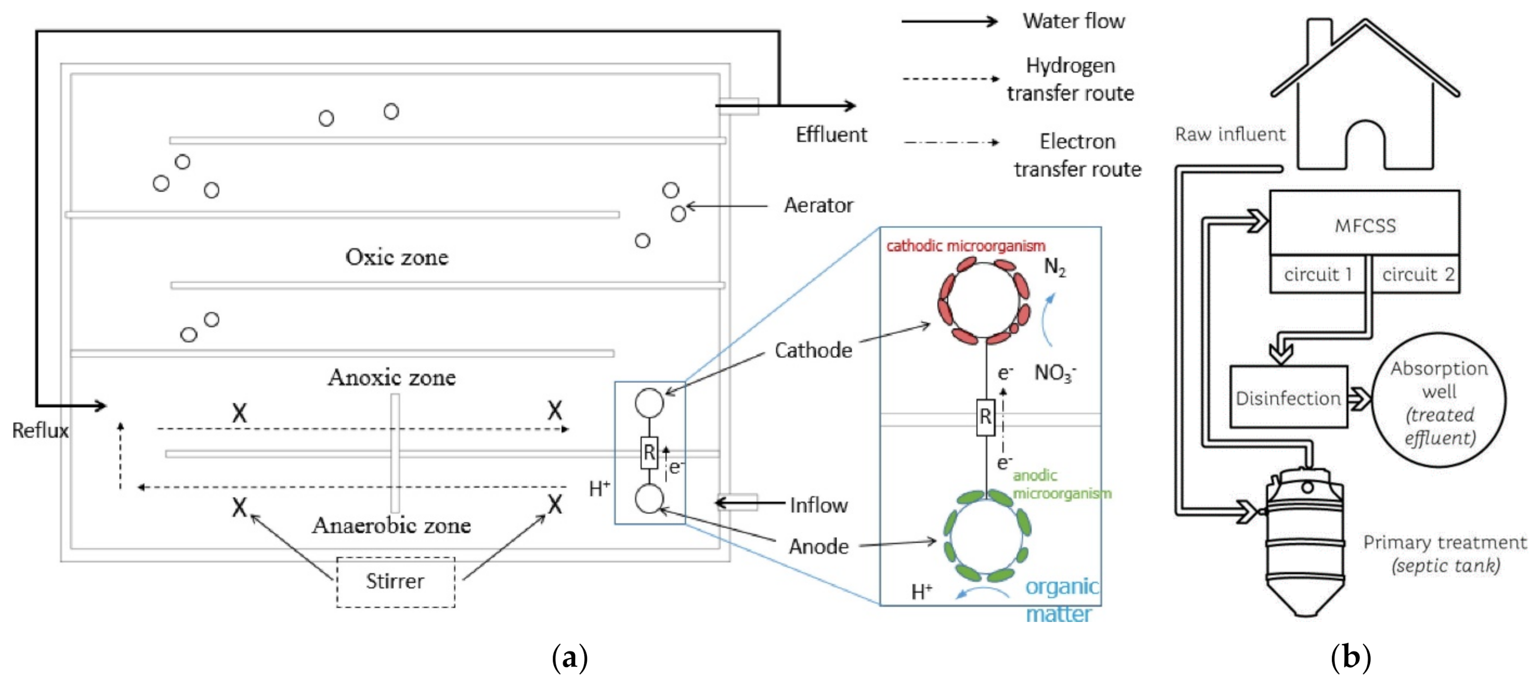
In recent years, as shown in Table 1, MFC scale-up studies have mainly targeted two applications—wastewater treatment via a standalone MFC unit or a hybrid/coupled system, and as power sources to produce off-grid energy. The substrates used are mainly municipal/domestic wastewaters. As reviewed in the previous sections, MFCs can be scaled up for wastewater treatment via stacking and/or the use of a modified electrode module. When coupled with another wastewater treatment unit, for instance, an anaerobic digester (AD), with a total AD-MFC size of 45 m3, a maximum current density of 1.25 A/m2 and COD removal of 35% were achieved from pre-treated pharmaceutical wastewater [16]. An MFC was also integrated into an anaerobic-anoxic-oxic (AO/O) system, and thus known as a hybrid system combining the features of the two units, with a total volume of 1 m3 (Figure 5a) for domestic wastewater treatment and power generation simultaneously [42]. Under an HRT of 18 h, temperature of 8–23 °C and recirculation ratio of 200%, a maximum current density of 3.6 mW/m3 and COD removal of 95% were achieved during its one-year operation. In Tang et al. [43], an MFC was coupled with a constructed wetland (CW), yielding energy recovery of 0.448 W/m3 and COD removal of 92% in treating dewatered alum sludge.
Notably, a recent study conducted by Valladares Linares et al. [23] demonstrated the feasibility and sustainability of a coupled septic tank-MFC-disinfection system for residential wastewater treatment. As shown in Figure 5b, the raw influent generated from a house of five inhabitants flowed to the 1300 L septic tank by gravity, then to the 700 L AQUOX® MFC consisting of two stacks of 9 MFC units, and finally to a disinfection system with sodium hypochlorite. An ultra-low energy consumption unit consisting of capacitors and microcontrollers harvested and stored energy from the MFC. The system was deemed sustainable and feasible as no external energy was required, and the treated effluent complied with the local discharge standard.
MFCs were also scaled up to be used as power sources. Following the publications on food-fueled robots, such as the Gastrobot [50] and Ecobot series [51], in recent years, single-chamber large-scale MFCs, such as sediment MFCs [24,44,45,46] and self-stratifying MFCs [47], were developed to provide off-grid energy. The self-stratifying stacked MFC known as PEE-POWER® was applied in a field test involving 250,000 people and demonstrated its ability to treat undiluted urine while generating power, which was then stored in a battery bank providing lighting at night [47]. An MFC was also developed for the purpose of cellphone and remote system charging [15], and lithium battery stack charging [26]. In addition to integrating MFCs into an existing WWTP via a standalone or hybrid system, serving as power sources to provide off-grid energy, MFCs are also evaluated widely as biosensors for in situ assessments (not shown in Table 1), for the detection of pollutants [52,53], metals [54,55], toxicity [56] and ship movements [57].
There is also a different family of the bioelectrochemical system—the microbial electrolysis cell (MEC, not listed in Table 1). In the MEC, external voltage (usually around 0.2–0.8 V) was supplied between the electrodes producing either electricity, hydrogen or methane [58]. MECs are also commonly tested for wastewater treatment and nutrient recovery to produce the clean hydrogen energy [59,60].

3. Challenges and Future Direction

A number of challenges have been identified from the scale-up studies. The top consideration would be the cost effectiveness of these MFCs. The capital costs of the scale-up system range from USD 735/m3 to 36,000/m3 [16,29]. The electrodes (especially the cathode) and membrane have been the primary culprits of the high cost of an MFC system [30,61].
Therefore, the recommended approach for scale up would be developing cost-effective reactor components and configuration. The focus of recent studies has been slowly shifted from membraned MFCs to membrane-less MFCs [46,47], or MFCs with low-cost membranes, e.g., dynamic membranes [21], glass fiber separators [31] and nano-filtration membranes [41]. Apart from the capital cost, operational costs such as pumping effluent and mixing are also detrimental to the energy usage and cost [62]. For this reason, among the MFC systems reviewed, submergible and stackable electrode modules, or sediment SCMFC types (Benthic MFCs), seem to stand out from the rest because these units are submergible, single-chambered and integrated directly into the existing treatment tanks; no additional pumps are required for feeding, discharging and aerating, which is more cost effective and sustainable.
The next challenge which is also of paramount importance is boosting the output yields. MFCs are generally known to produce much lower energy than other fuel cells or batteries. Owing to the highly non-linear inverse relationship between the power and size, the stacking of small MFC units via series and/or parallel connections has been proven to increase the current and voltage output. However, stacking presents new issues due to kinetics imbalance, i.e., the formation of shunt current, voltage reversal and current reversal [32,39,63,64]. Different circuit connections also result in changes in microbial communities [25]. Wu et al. [39] suggested lowering the external resistances of the stacked MFC system to reduce current reversal problems, especially for parallel connections. Recently, Kim et al. [32] presented some realistic approaches to control and suppress the voltage reversal issue, such as using enriched electroactive microorganisms, altering and optimizing the circuitry mode. Careful design of the circuitry coupled with the use of a maximum power point tracker has been demonstrated to eliminate voltage reversal in series connections [35,65], achieving enhanced Coulombic efficiency and limiting the methanogenic activity of the bacteria [66,67].
In addition to the cost and output yield limitations, there are operational challenges, which require consideration of the substrate characteristics, operating conditions and long-term durability. Many studies have been conducted on investigating and optimizing the operating parameters, such as temperature [68], pH [69,70], organic loading rate [71], substrate salinity [72], conductivity [73], start-up [74] and hydraulic retention time [75]. However, parametric and optimization studies usually target certain substrate or substrate types. Therefore, there is still a need to conduct parametric and optimization studies on a case-by-case basis. High salt content in wastewater might cause severe inorganic fouling [31] due to blockage of the precipitates which are predominantly calcium (89%) and magnesium (7%) [76,77]. Therefore, long-term durability studies are required, especially regarding the possible biofouling, clogging and corrosion in the scale-up systems [20,30,78].
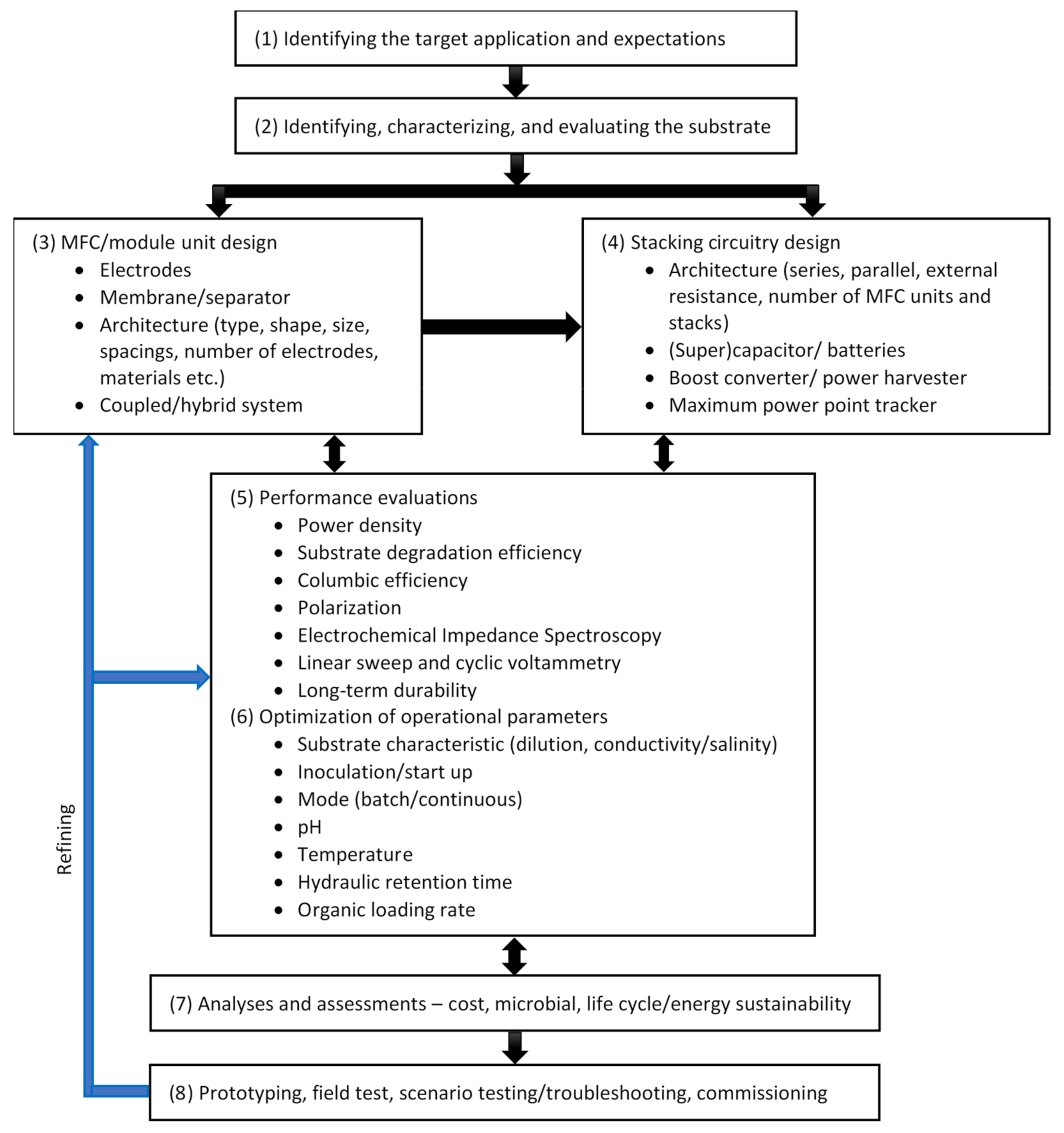
In view of the above challenges, a flow chart is presented in Figure 6 to provide a framework for ameliorating the current limitations faced in scaling up MFCs.
Depending upon the application purpose, and the type and characteristics of the substrate, small-scale MFCs (or electrode modules) can be designed by considering and justifying the types and designs of electrodes, membranes and the system architecture (type, shape, size, spacings, number of electrodes and materials). Hybrid or coupled systems are also a potential area to improve the degradable potential of the substrate [79]. The MFC design is then incorporated into the stacking circuitry design stage to obtain the optimized number of MFC units, stacks and circuit connections, and to incorporate a (super)capacitor/batteries, a converter/harvester and a maximum power point tracker. In order to achieve maximum possible energy recovery, substrate degradation and Coulombic efficiency, optimizations of the operational parameters are essential, as these parameters are closely related to the MFC and circuitry designs. These parameters include altering substrate characteristics (to improve the conductivity of the anolyte), inoculation methods (to improve the start-up time required), mode of operation, pH, temperature, hydraulic retention time and organic loading. Analyses and assessments, including cost, microbial, life cycle or energy sustainability, could greatly aid the feasibility study of the scale-up MFC, prior to the prototyping, field test and commissioning.

4. Conclusions

Microbial fuel cell systems have shown promising performances at a large scale, particularly in the areas of bioenergy generation from wastewater treatment and off-grid power sources. However, this is just the beginning of microbial fuel cell commercialization. There are various challenges involved in scaling up prior to commercialization. This paper reviewed the MFC scale-up research work in the last five years, and based on the trend observed, proposed a framework outlining the areas for current and future studies. Submergible and stackable MFCs or electrode modules are the potential area for further studies and development. Utilizing membrane-less systems or low-cost membranes further lowers the cost of MFCs.
There are vast future opportunities for the widespread application of MFC technology. The most profound application would be in wastewater treatment. Submergible and stackable MFCs can be integrated into any treatment tank of a wastewater treatment plant to further degrade the remaining organic matters and produce additional energy for plant operation. MFCs are also suitable to be coupled with an existing wastewater treatment unit, for instance, an anaerobic digester or primary clarifier, to reduce the effluent to well below the discharge standard while extracting additional power. MFCs can generate not only bioenergy, but also hydrogen when supplied with an external voltage. Another application of MFC technology which is rising in demand is the in situ bioremediation, utilizing sediment or Benthic MFCs. These MFCs can remediate sediments for organic matter removal or nutrient recovery while producing off-grid energy. Last but not least, MFCs are also widely studied as remote sensors for organic pollutants, metals, toxicity, etc.
For the realization of MFC technology, MFC unit/module design, stacking circuitry design, operational parameter optimization, cost analysis, microbial analysis, life cycle assessment and energy sustainability are the important research areas which require cross-disciplinary collaborations, from engineers/scientists (chemical, process, electrical, mechanical, environmental, civil and computer science), to microbiologists, technicians, governmental bodies and business investors.

Author Contributions

Conceptualization and Writing—Original Draft Preparation, W.H.T.; Supervision and Writing—Review and Editing, S.C.; Writing—Review and Editing and Funding Acquisition, J.W.L. and M.M.; Formal Analysis, K.-L.P.; Methodology, T.J.T.; Data Curation, Y.J.C.; Visualization, H.-W.F.; Project Administration, C.-M.H.; Resources, T.C.-K.Y. All authors have read and agreed to the published version of the manuscript.

Funding

The financial support from Universitas Islam Riau (UIR), Indonesia, via an international grant with the cost center of 015ME0-164; Universitas Pertamina, Indonesia, via an international grant with the cost center of 015ME0-196; Research Collaboration Grant UTP-UMP-UMT-UCTS with the cost center of 015MD0-019; and HICoE-Centre for Biofuel and Biochemical Research with the cost center of 015MA0-052 is gratefully acknowledged.

Institutional Review Board Statement

Not applicable.

Informed Consent Statement

Not applicable.

Conflicts of Interest

The authors declare no conflict of interest.

References

  1. Lewis, C.W. Biomass through the ages. Biomass 1981, 1, 5–15. [Google Scholar] [CrossRef]
  2. Höök, M.; Tang, X. Depletion of fossil fuels and anthropogenic climate change—A review. Energy Policy 2013, 52, 797–809. [Google Scholar] [CrossRef] [Green Version]
  3. Guo, M.; Song, W.; Buhain, J. Bioenergy and biofuels: History, status, and perspective. Renew. Sustain. Energy Rev. 2015, 42, 712–725. [Google Scholar] [CrossRef]
  4. Long, H.; Li, X.; Wang, H.; Jia, J. Biomass resources and their bioenergy potential estimation: A review. Renew. Sustain. Energy Rev. 2013, 26, 344–352. [Google Scholar] [CrossRef]
  5. Dewan, A.; Beyenal, H.; Lewandowski, Z. Scaling up microbial fuel cells. Environ. Sci. Technol. 2008, 42, 7643–7648. [Google Scholar] [CrossRef]
  6. Ieropoulos, I.; Greenman, J.; Melhuish, C. Microbial fuel cells based on carbon veil electrodes: Stack configuration and scalability. Int. J. Energy Res. 2008, 32, 1228–1240. [Google Scholar] [CrossRef]
  7. Logan, B.E. Microbial Fuel Cells; John Wiley & Sons: Hoboken, NJ, USA, 2008. [Google Scholar]
  8. Ge, Z.; Zhang, F.; Grimaud, J.; Hurst, J.; He, Z. Long-term investigation of microbial fuel cells treating primary sludge or digested sludge. Bioresour. Technol. 2013, 136, 509–514. [Google Scholar] [CrossRef]
  9. Kumar, R.; Singh, L.; Wahid, Z.A.; Din, M.F.M. Exoelectrogens in microbial fuel cells toward bioelectricity generation: A review. Int. J. Energy Res. 2015, 39, 1048–1067. [Google Scholar] [CrossRef]
  10. Trapero, J.R.; Horcajada, L.; Linares, J.J.; Lobato, J. Is microbial fuel cell technology ready? An economic answer towards industrial commercialization. Appl. Energy 2017, 185, 698–707. [Google Scholar] [CrossRef]
  11. Pant, D.; Van Bogaert, G.; Diels, L.; Vanbroekhoven, K. A review of the substrates used in microbial fuel cells (MFCs) for sustainable energy production. Bioresour. Technol. 2010, 101, 1533–1543. [Google Scholar] [CrossRef]
  12. Pant, D.; Van Bogaert, G.; Alvarez-Gallego, Y.; Diels, L.; Vanbroekhoven, K. Evaluation of bioelectrogenic potential of four industrial effluents as substrate for low cost Microbial Fuel Cells operation. Environ. Eng. Manag. J. (Eemj) 2016, 15. [Google Scholar] [CrossRef]
  13. Liu, Z.; Liu, J.; Zhang, S.; Su, Z. Study of operational performance and electrical response on mediator-less microbial fuel cells fed with carbon-and protein-rich substrates. Biochem. Eng. J. 2009, 45, 185–191. [Google Scholar] [CrossRef]
  14. Lu, N.; Zhou, S.-G.; Zhuang, L.; Zhang, J.-T.; Ni, J.-R. Electricity generation from starch processing wastewater using microbial fuel cell technology. Biochem. Eng. J. 2009, 43, 246–251. [Google Scholar] [CrossRef]
  15. Walter, X.A.; Stinchcombe, A.; Greenman, J.; Ieropoulos, I. Urine transduction to usable energy: A modular MFC approach for smartphone and remote system charging. Appl. Energy 2017, 192, 575–581. [Google Scholar] [CrossRef] [Green Version]
  16. Wang, A.-J.; Wang, H.-C.; Cheng, H.-Y.; Liang, B.; Liu, W.-Z.; Han, J.-L.; Zhang, B.; Wang, S.-S. Electrochemistry-stimulated environmental bioremediation: Development of applicable modular electrode and system scale-up. Environ. Sci. Ecotechnol. 2020, 3, 100050. [Google Scholar] [CrossRef]
  17. Walter, X.A.; Santoro, C.; Greenman, J.; Ieropoulos, I.A. Scalability and stacking of self-stratifying microbial fuel cells treating urine. Bioelectrochemistry 2020, 133, 107491. [Google Scholar] [CrossRef]
  18. Vilajeliu-Pons, A.; Puig, S.; Salcedo-Dávila, I.; Balaguer, M.; Colprim, J. Long-term assessment of six-stacked scaled-up MFCs treating swine manure with different electrode materials. Environ. Sci. Water Res. Technol. 2017, 3, 947–959. [Google Scholar] [CrossRef] [Green Version]
  19. Yellappa, M.; Sravan, J.S.; Sarkar, O.; Reddy, Y.V.R.; Mohan, S.V. Modified conductive polyaniline-carbon nanotube composite electrodes for bioelectricity generation and waste remediation. Bioresour. Technol. 2019, 284, 148–154. [Google Scholar] [CrossRef] [PubMed]
  20. Huang, S.; Zhang, J.; Pi, J.; Gong, L.; Zhu, G. Long-term electricity generation and denitrification performance of MFCs with different exchange membranes and electrode materials. Bioelectrochemistry 2021, 140, 107748. [Google Scholar] [CrossRef]
  21. He, W.; Dong, Y.; Li, C.; Han, X.; Liu, G.; Liu, J.; Feng, Y. Field tests of cubic-meter scale microbial electrochemical system in a municipal wastewater treatment plant. Water Res. 2019, 155, 372–380. [Google Scholar] [CrossRef]
  22. Asensio, Y.; Mansilla, E.; Fernandez-Marchante, C.; Lobato, J.; Cañizares, P.; Rodrigo, M. Towards the scale-up of bioelectrogenic technology: Stacking microbial fuel cells to produce larger amounts of electricity. J. Appl. Electrochem. 2017, 47, 1115–1125. [Google Scholar] [CrossRef]
  23. Valladares Linares, R.; Domínguez-Maldonado, J.; Rodríguez-Leal, E.; Patrón, G.; Castillo-Hernández, A.; Miranda, A.; Diaz Romero, D.; Moreno-Cervera, R.; Camara-chale, G.; Borroto, C.G.; et al. Scale up of microbial fuel cell stack system for residential wastewater treatment in continuous mode operation. Water 2019, 11, 217. [Google Scholar] [CrossRef] [Green Version]
  24. Prasad, J.; Tripathi, R.K. Effect of sediment microbial fuel cell stacks on 9 V/12 V DC power supply. Int. J. Hydrog. Energy 2021, 46, 14628–14638. [Google Scholar] [CrossRef]
  25. Estrada-Arriaga, E.B.; Hernández-Romano, J.; García-Sánchez, L.; Garcés, R.A.G.; Bahena-Bahena, E.O.; Guadarrama-Pérez, O.; Chavez, G.E.M. Domestic wastewater treatment and power generation in continuous flow air-cathode stacked microbial fuel cell: Effect of series and parallel configuration. J. Environ. Manag. 2018, 214, 232–241. [Google Scholar] [CrossRef]
  26. Fischer, F.; Sugnaux, M.; Savy, C.; Hugenin, G. Microbial fuel cell stack power to lithium battery stack: Pilot concept for scale up. Appl. Energy 2018, 230, 1633–1644. [Google Scholar] [CrossRef]
  27. Greenman, J.; Ieropoulos, I.A. Allometric scaling of microbial fuel cells and stacks: The lifeform case for scale-up. J. Power Sources 2017, 356, 365–370. [Google Scholar] [CrossRef]
  28. Gajda, I.; Greenman, J.; Ieropoulos, I.A. Recent advancements in real-world microbial fuel cell applications. Curr. Opin. Electrochem. 2018, 11, 78–83. [Google Scholar] [CrossRef]
  29. Liang, P.; Duan, R.; Jiang, Y.; Zhang, X.; Qiu, Y.; Huang, X. One-year operation of 1000-L modularized microbial fuel cell for municipal wastewater treatment. Water Res. 2018, 141, 1–8. [Google Scholar] [CrossRef]
  30. Ge, Z.; He, Z. Long-term performance of a 200 liter modularized microbial fuel cell system treating municipal wastewater: Treatment, energy, and cost. Environ. Sci. Water Res. Technol. 2016, 2, 274–281. [Google Scholar] [CrossRef] [Green Version]
  31. Hiegemann, H.; Littfinski, T.; Krimmler, S.; Lübken, M.; Klein, D.; Schmelz, K.-G.; Ooms, K.; Pant, D.; Wichern, M. Performance and inorganic fouling of a submergible 255 L prototype microbial fuel cell module during continuous long-term operation with real municipal wastewater under practical conditions. Bioresour. Technol. 2019, 294, 122227. [Google Scholar] [CrossRef]
  32. Kim, B.; Mohan, S.V.; Fapyane, D.; Chang, I.S. Controlling voltage reversal in microbial fuel cells. Trends Biotechnol. 2020, 38, 667–678. [Google Scholar] [CrossRef] [PubMed]
  33. Wen, Q.; Wu, Y.; Cao, D.; Zhao, L.; Sun, Q. Electricity generation and modeling of microbial fuel cell from continuous beer brewery wastewater. Bioresour. Technol. 2009, 100, 4171–4175. [Google Scholar] [CrossRef] [PubMed]
  34. Mateo, S.; Cañizares, P.; Fernandez-Morales, F.J.; Rodrigo, M.A. A critical view of microbial fuel cells: What is the next stage? Chemsuschem 2018, 11, 4183–4192. [Google Scholar] [CrossRef] [PubMed]
  35. Blatter, M.; Delabays, L.; Furrer, C.; Huguenin, G.; Cachelin, C.P.; Fischer, F. Stretched 1000-L microbial fuel cell. J. Power Sources 2021, 483, 229130. [Google Scholar] [CrossRef]
  36. Das, I.; Ghangrekar, M.; Satyakam, R.; Srivastava, P.; Khan, S.; Pandey, H. On-site sanitary wastewater treatment system using 720-L stacked microbial fuel cell: Case study. J. Hazard. ToxicRadioact. Waste 2020, 24, 04020025. [Google Scholar] [CrossRef]
  37. Babanova, S.; Jones, J.; Phadke, S.; Lu, M.; Angulo, C.; Garcia, J.; Carpenter, K.; Cortese, R.; Chen, S.; Phan, T. Continuous flow, large-scale, microbial fuel cell system for the sustained treatment of swine waste. Water Environ. Res. 2020, 92, 60–72. [Google Scholar] [CrossRef]
  38. Rossi, R.; Jones, D.; Myung, J.; Zikmund, E.; Yang, W.; Gallego, Y.A.; Pant, D.; Evans, P.J.; Page, M.A.; Cropek, D.M.; et al. Evaluating a multi-panel air cathode through electrochemical and biotic tests. Water Res. 2019, 148, 51–59. [Google Scholar] [CrossRef]
  39. Wu, S.; Li, H.; Zhou, X.; Liang, P.; Zhang, X.; Jiang, Y.; Huang, X. A novel pilot-scale stacked microbial fuel cell for efficient electricity generation and wastewater treatment. Water Res. 2016, 98, 396–403. [Google Scholar] [CrossRef]
  40. Hiegemann, H.; Herzer, D.; Nettmann, E.; Lübken, M.; Schulte, P.; Schmelz, K.-G.; Gredigk-Hoffmann, S.; Wichern, M. An integrated 45 L pilot microbial fuel cell system at a full-scale wastewater treatment plant. Bioresour. Technol. 2016, 218, 115–122. [Google Scholar] [CrossRef]
  41. Lu, M.; Chen, S.; Babanova, S.; Phadke, S.; Salvacion, M.; Mirhosseini, A.; Chan, S.; Carpenter, K.; Cortese, R.; Bretschger, O. Long-term performance of a 20-L continuous flow microbial fuel cell for treatment of brewery wastewater. J. Power Sources 2017, 356, 274–287. [Google Scholar] [CrossRef]
  42. Liu, R.; Tursun, H.; Hou, X.; Odey, F.; Li, Y.; Wang, X.; Xie, T. Microbial community dynamics in a pilot-scale MFC-AA/O system treating domestic sewage. Bioresour. Technol. 2017, 241, 439–447. [Google Scholar] [CrossRef] [PubMed]
  43. Tang, C.; Zhao, Y.; Kang, C.; Yang, Y.; Morgan, D.; Xu, L. Towards concurrent pollutants removal and high energy harvesting in a pilot-scale CW-MFC: Insight into the cathode conditions and electrodes connection. Chem. Eng. J. 2019, 373, 150–160. [Google Scholar] [CrossRef]
  44. Li, H.; He, W.; Qu, Y.; Li, C.; Tian, Y.; Feng, Y. Pilot-scale benthic microbial electrochemical system (BMES) for the bioremediation of polluted river sediment. J. Power Sources 2017, 356, 430–437. [Google Scholar] [CrossRef]
  45. Li, H.; Tian, Y.; Qu, Y.; Qiu, Y.; Liu, J.; Feng, Y. A pilot-scale benthic microbial electrochemical system (BMES) for enhanced organic removal in sediment restoration. Sci. Rep. 2017, 7, 1–9. [Google Scholar] [CrossRef] [PubMed] [Green Version]
  46. Prasad, J.; Tripathi, R.K. Scale-up and control the voltage of sediment microbial fuel cell for charging a cell phone. Biosens. Bioelectron. 2021, 172, 112767. [Google Scholar] [CrossRef] [PubMed]
  47. Walter, X.A.; Merino-Jiménez, I.; Greenman, J.; Ieropoulos, I. PEE POWER® urinal II–Urinal scale-up with microbial fuel cell scale-down for improved lighting. J. Power Sources 2018, 392, 150–158. [Google Scholar] [CrossRef]
  48. Guo, K.; Prévoteau, A.; Patil, S.A.; Rabaey, K. Engineering electrodes for microbial electrocatalysis. Curr. Opin. Biotechnol. 2015, 33, 149–156. [Google Scholar] [CrossRef]
  49. Bouwman, L.; Van Houtven, D.; Pant, D.; Alvarez Gallego, Y.; Vanbroekhoven, K. Carbon Based Electrode with Large Geometric Dimensions. U.S. Patent 16/753,027, 17 September 2020. [Google Scholar]
  50. Wilkinson, S. “Gastrobots”—Benefits and challenges of microbial fuel cells in foodpowered robot applications. Auton. Robot. 2000, 9, 99–111. [Google Scholar] [CrossRef]
  51. Ieropoulos, I.; Melhuish, C.; Greenman, J. Artificial metabolism: Towards true energetic autonomy in artificial life. In Proceedings of the European Conference on Artificial Life, Dortmund, Germany, 14–17 September 2003; pp. 792–799. [Google Scholar]
  52. Yi, Y.; Xie, B.; Zhao, T.; Li, Z.; Stom, D.; Liu, H. Effect of external resistance on the sensitivity of microbial fuel cell biosensor for detection of different types of pollutants. Bioelectrochemistry 2019, 125, 71–78. [Google Scholar] [CrossRef]
  53. Do, M.H.; Ngo, H.H.; Guo, W.; Chang, S.W.; Nguyen, D.D.; Liu, Y.; Varjani, S.; Kumar, M. Microbial fuel cell-based biosensor for online monitoring wastewater quality: A critical review. Sci. Total Environ. 2020, 712, 135612. [Google Scholar] [CrossRef]
  54. Khan, A.; Salama, E.-S.; Chen, Z.; Ni, H.; Zhao, S.; Zhou, T.; Pei, Y.; Sani, R.K.; Ling, Z.; Liu, P. A novel biosensor for zinc detection based on microbial fuel cell system. Biosens. Bioelectron. 2020, 147, 111763. [Google Scholar] [CrossRef]
  55. Wu, L.-C.; Tsai, T.-H.; Liu, M.-H.; Kuo, J.-L.; Chang, Y.-C.; Chung, Y.-C. A green microbial fuel cell-based biosensor for in situ chromium (VI) measurement in electroplating wastewater. Sensors 2017, 17, 2461. [Google Scholar] [CrossRef] [PubMed]
  56. Zhou, T.; Han, H.; Liu, P.; Xiong, J.; Tian, F.; Li, X. Microbial fuels cell-based biosensor for toxicity detection: A review. Sensors 2017, 17, 2230. [Google Scholar] [CrossRef] [PubMed]
  57. Arias-Thode, Y.M.; Hsu, L.; Anderson, G.; Babauta, J.; Fransham, R.; Obraztsova, A.; Tukeman, G.; Chadwick, D.B. Demonstration of the SeptiStrand benthic microbial fuel cell powering a magnetometer for ship detection. J. Power Sources 2017, 356, 419–429. [Google Scholar] [CrossRef]
  58. Katuri, K.P.; Ali, M.; Saikaly, P.E. The role of microbial electrolysis cell in urban wastewater treatment: Integration options, challenges, and prospects. Curr. Opin. Biotechnol. 2019, 57, 101–110. [Google Scholar] [CrossRef] [PubMed]
  59. Zamora, P.; Georgieva, T.; Ter Heijne, A.; Sleutels, T.H.; Jeremiasse, A.W.; Saakes, M.; Buisman, C.J.; Kuntke, P. Ammonia recovery from urine in a scaled-up Microbial Electrolysis Cell. J. Power Sources 2017, 356, 491–499. [Google Scholar] [CrossRef]
  60. Liang, D.; He, W.; Li, C.; Wang, F.; Crittenden, J.C.; Feng, Y. Remediation of nitrate contamination by membrane hydrogenotrophic denitrifying biofilm integrated in microbial electrolysis cell. Water Res. 2021, 188, 116498. [Google Scholar] [CrossRef]
  61. Rozendal, R.A.; Hamelers, H.V.; Rabaey, K.; Keller, J.; Buisman, C.J. Towards practical implementation of bioelectrochemical wastewater treatment. Trends Biotechnol. 2008, 26, 450–459. [Google Scholar] [CrossRef]
  62. Tommasi, T.; Lombardelli, G. Energy sustainability of Microbial Fuel Cell (MFC): A case study. J. Power Sources 2017, 356, 438–447. [Google Scholar] [CrossRef]
  63. An, J.; Nam, J.; Kim, B.; Lee, H.-S.; Kim, B.H.; Chang, I.S. Performance variation according to anode-embedded orientation in a sediment microbial fuel cell employing a chessboard-like hundred-piece anode. Bioresour. Technol. 2015, 190, 175–181. [Google Scholar] [CrossRef]
  64. Chen, S.; Patil, S.A.; Brown, R.K.; Schröder, U. Strategies for optimizing the power output of microbial fuel cells: Transitioning from fundamental studies to practical implementation. Appl. Energy 2019, 233, 15–28. [Google Scholar] [CrossRef]
  65. Boghani, H.C.; Papaharalabos, G.; Michie, I.; Fradler, K.R.; Dinsdale, R.M.; Guwy, A.J.; Ieropoulos, I.; Greenman, J.; Premier, G.C.J.J.o.P.S. Controlling for peak power extraction from microbial fuel cells can increase stack voltage and avoid cell reversal. J. Power Sources 2014, 269, 363–369. [Google Scholar] [CrossRef]
  66. Molognoni, D.; Puig, S.; Balaguer, M.D.; Liberale, A.; Capodaglio, A.G.; Callegari, A.; Colprim, J. Reducing start-up time and minimizing energy losses of Microbial Fuel Cells using Maximum Power Point Tracking strategy. J. Power Sources 2014, 269, 403–411. [Google Scholar] [CrossRef]
  67. Lobo, F.L.; Wang, X.; Ren, Z.J. Energy harvesting influences electrochemical performance of microbial fuel cells. J. Power Sources 2017, 356, 356–364. [Google Scholar] [CrossRef]
  68. Song, Y.; An, J.; Chae, K.J. Effect of temperature variation on the performance of microbial fuel cells. Energy Technol. 2017, 5, 2163–2167. [Google Scholar] [CrossRef]
  69. Kumar, P.; Mungray, A.K. Microbial fuel cell: Optimizing pH of anolyte and catholyte by using taguchi method. Environ. Prog. Sustain. Energy 2016, 36, 120–128. [Google Scholar] [CrossRef]
  70. Yang, W.; Li, J.; Ye, D.; Zhang, L.; Zhu, X.; Liao, Q. A hybrid microbial fuel cell stack based on single and double chamber microbial fuel cells for self-sustaining pH control. J. Power Sources 2016, 306, 685–691. [Google Scholar] [CrossRef]
  71. Ye, Y.; Ngo, H.H.; Guo, W.; Chang, S.W.; Nguyen, D.D.; Liu, Y.; Nghiem, L.D.; Zhang, X.; Wang, J. Effect of organic loading rate on the recovery of nutrients and energy in a dual-chamber microbial fuel cell. Bioresour. Technol. 2019, 281, 367–373. [Google Scholar] [CrossRef]
  72. Guo, F.; Luo, H.; Shi, Z.; Wu, Y.; Liu, H. Substrate salinity: A critical factor regulating the performance of microbial fuel cells, a review. Sci. Total Environ. 2020, 143021. [Google Scholar] [CrossRef]
  73. Stefanova, A.; Angelov, A.; Bratkova, S.; Genova, P.; Nikolova, K. Influence of electrical conductivity and temperature in a microbial fuel cell for treatment of mining waste water. Ann. Constantin Brancusi Univ. Targu Jiu-Lett. Soc. Sci. Ser. 2018, 3, 18–24. [Google Scholar]
  74. Vicari, F.; Mateo, S.; Fernandez-Morales, F.; Cañizares, P.; Galia, A.; Scialdone, O.; Rodrigo, M. Influence of the methodology of inoculation in the performance of air-breathing microbial fuel cells. J. Electroanal. Chem. 2017, 803, 81–88. [Google Scholar] [CrossRef]
  75. Ye, Y.; Ngo, H.H.; Guo, W.; Chang, S.W.; Nguyen, D.D.; Zhang, X.; Zhang, S.; Luo, G.; Liu, Y. Impacts of hydraulic retention time on a continuous flow mode dual-chamber microbial fuel cell for recovering nutrients from municipal wastewater. Sci. Total Environ. 2020, 734, 139220. [Google Scholar] [CrossRef] [PubMed]
  76. Rau, G. Electrochemical splitting of calcium carbonate to increase solution alkalinity: Implications for mitigation of carbon dioxide and ocean acidity. Environ. Sci. Technol. 2008, 42, 8935–8940. [Google Scholar] [CrossRef] [PubMed]
  77. Tlili, M.; Benamor, M.; Gabrielli, C.; Perrot, H.; Tribollet, B. Influence of the interfacial pH on electrochemical CaCO3 precipitation. J. Electrochem. Soc. 2003, 150, C765. [Google Scholar] [CrossRef]
  78. Zhang, E.; Wang, F.; Yu, Q.; Scott, K.; Wang, X.; Diao, G. Durability and regeneration of activated carbon air-cathodes in long-term operated microbial fuel cells. J. Power Sources 2017, 360, 21–27. [Google Scholar] [CrossRef] [Green Version]
  79. Zhang, Y.; Liu, M.; Zhou, M.; Yang, H.; Liang, L.; Gu, T. Microbial fuel cell hybrid systems for wastewater treatment and bioenergy production: Synergistic effects, mechanisms and challenges. Renew. Sustain. Energy Rev. 2019, 103, 13–29. [Google Scholar] [CrossRef]
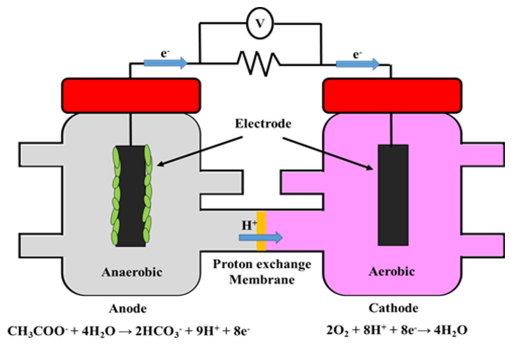
Figure 1. Schematic of the basic components of a microbial fuel cell.
Processes 09 00985 g001
Figure 2. (a) Allometric scaling for MFCs (individual units and stacks). The dashed line shows a linear slope for comparison of super- or sub-linear gradients. Group 2 is a range of “air-breathing” MFCs made from polymeric composites or ceramic membranes; Group 3 refers to a fixed-size MFC using Shewanella specifies monoculture; Group 4 refers to three sizes of single MFC units (small, medium and large); Group 5 is based on small-scale (124 μL) tubular MFCs made out of Nafion tube; Group 6 refers to a single Nanocure MFC and a stack of 48 such units; Group 7 shows scaling from 1 to 22 units in a single box, using ceramic MFCs; Group 8 shows laboratory data from a membrane-less MFC where n = 21 units in one “small box” and n = 38 units in one “larger box”, reprinted from [27]. Copyright (2017), with permission from Elsevier; (b) power density versus anodic area, reprinted with permission from [5]. Copyright (2008) American Chemical Society.
Processes 09 00985 g002
Figure 3. (a) Stretched 1000 L MFC stack, reprinted from [35]. Copyright (2018), with permission from Elsevier; (b) modularized 1000 L MFC, reprinted from [29]. Copyright (2018), with permission from Elsevier; (c) 110 L air-cathode MFC [27], Copyright (2019). with permission from John Wiley and Sons.
Processes 09 00985 g003
Figure 4. Pictures of the (a) air-facing and (b) solution-facing side of the patented multi-panel electrode module, reprinted from [38]. Copyright (2019), with permission from Elsevier; (c) sandwiched corrugated electrode [16].
Processes 09 00985 g004
Figure 5. (a) Hybrid MFC-AA/O system for domestic wastewater treatment and power generation, reprinted from [42]. Copyright (2017), with permission from Elsevier; (b) hybrid septic tank-MFC-disinfection system for residential wastewater treatment and power generation [23].
Processes 09 00985 g005
Figure 6. The proposed framework for MFC scale-up studies.
Processes 09 00985 g006
Table 1. Summary of MFC scale-up studies in the last five years (2016–2020).
Reactor TypeSubstrateCOD, Conductivity, pHAnode (Number)Cathode
(Number), Catholyte
MembraneMax P (W/m3, Unless Specified)COD Removal (%)CE (%)Reference
Stacked or scale-up MFCs with volume > 10 L for wastewater treatment:
1Movable, 1.5 m3 (Primary clarifier- DCMFC-Secondary clarifier)Primary effluent0.26 g/LGFB (8)Bio-GFB (7), Anode effluentDynamic (microbial) membrane0.491-[21]
2DCMFC, 64 units, 1000 LMunicipal ww0.2–0.45 g/L
pH 7.2
RVCRVC, GroundwaterVANA- Dion0.234–955–15[35]
3DCMFC, 50 units, 1000 LMunicipal ww0.08–0.25 g/LGACGAC, Artificial catholyteCEM6070–9041–75[29]
4SCMFC, 6 units, 720 LSanitary sewage1–8.2 g/LC feltCoZnFeO or SnCu/C feltClayware0.08587-[36]
5Submergible MFC, 255 LMunicipal ww0.205 g/L
540 mS/m
pH 7
GFB (10)SS-AC (16, VitoCORE®)Glass fiber separator0.34130[31]
6DCMFC, 96 units, 200 LPrimary effluent0.16 g/LCFBC cloth/N-AC, Aerobic effluentCEM175-[30]
7SCMFC, 12 units, 110 LSwine ww1 g/L
pH 7.5
GFB (20)Gas diffusion cathodeNone0.3665-[37]
8SCMFC, 85 LDomestic ww0.428 g/LGFB (22)SS-AC (15, VitoCORE®)Glass fiber separator0.6058027[38]
9DCMFC, 72 LSynthetic ww0.2–1.2 g/L
pH 6.8–7.1
GAC/Ti meshGAC/Ti mesh, Desalination effluentCEM5197-[39]
10DCMFC, 6 units, 60 LSwine manure2.47 g/L
830 mS/m
pH 8.5
GGGR, AmmoniumAEM43617[18]
SSSS, AmmoniumAEM24017[18]
11SCMFC, 45 LPrimary effluent0.13 g/L
300–420 mS/m
GFB (8)Pt/C cloth/SS (2) None0.87514–6710–25[40]
12SCMFC, 40 units, 16 LMunicipal ww0.3 g/LC feltPb/C clothCEM4784-[25]
13DCMFC, 2 units, 20 LBrewery ww3.2 g/L
242 mS/m
pH 7
Modified C clothModified C clothNano- filtration membrane0.449514[41]
Hybrid/coupled MFC with volume > 10 L:
14AD-SCMFC (1 m3)Pre-treated pharmaceu- tical ww0.16–0.36 g/LC felt/G-SSC felt/G-SSIsolation pad1.25 A/m235-[16]
15Hybrid AA/O- SCMFC, 1 m3Domestic ww0.45–0.65 g/L
pH 7.5–8
CFB-SSCFB-SSNone0.003695-[42]
16Septic tank-SCMFC (18 units, 700 L) -DisinfectionDomestic ww789 g/L
pH 8
SS-GACC clothNafion 1170.000438722[23]
17CW-DCMFC, 30 LDewatered alum sludge0.5 g/LSS-C felt (4)SS-C felt, ASNone0.448920.36[43]
Scale-up MFC as off-grid power source:
18Sediment MFC, 350 LSynthetic ww-C meshACNone0.0064--[44]
19Sediment MFC, 195 LRiver sediment13.5 mS/m
pH 6.8–7.4
C meshAC/SSNone0.0415--[45]
20Sediment MFC, 72 units, 72 LRiver sediment water890 g/L
27.206 mS/m
pH 8
Copper Zinc None0.001923-[46]
Sediment MFC, 35 units, 35 LRiver sediment water890 g/L
27.206 mS/m
pH 8
Copper Zinc None0.0069--[24]
21Self-stratifying SCMFC (38 units), 19.2–57.6 L Urine5.6–6.8 g/L
pH 8.5–9.2
C veil fibersmicro-porous CNone7.3–9.948–881.6–3.8[47]
22DCMFC, 12 units, 12 LSynthetic ww-RVCPt/RVC, PBSNafion 11716.2 mW/m2--[26]
(SCMFC: single-chamber MFC; DCMFC: double-chamber MFC; ww: wastewater; C: carbon; CB: carbon brush; CFB: carbon fiber brush; GG: granular graphite; GR: granular rod; SS: stainless steel; GFB: graphite fiber brush; RVC: reticulated vitreous carbon; GAC: granular activated carbon; N-AC: nitrogen-doped activated carbon; AS: activated sludge; CEM: Cationic exchange membrane; AEM: Anionic exchange membrane; AD: anaerobic digester; CW: constructed wetlands; AA/O: anaerobic-anoxic/oxic; Ti: titanium; Pb: lead; Pt: platinum; PBS: phosphate buffer solution.)Similarly, in an experimental scale-up study conducted by Liang et al. [29] where a 1000 L modularized DCMFC comprising 50 stacked modules connected parallel to each other (Figure 3b), a maximum power density of 60 W/m3 was produced in treating municipal wastewater, with COD removal of 70–90% and CE of 41–75%. As shown in Table 1, the major differences of these studies [21,29,35] are the reactor design, type of electrodes and catholytes. In the movable DCMFC system [21], multiple electrodes made of graphite fiber brushes were used, with the effluent from anode chamber as the catholyte, whereas in the stretched DCMFC [35], reticulated vitreous carbon was used as the electrodes, with groundwater as the catholyte, and in the modularized DCMFC [29], granular activated carbon was used as the electrodes, with an artificial solution as the catholyte. In addition, these reactors also have different circuit architectures, hence the vast difference in the power densities.
Publisher’s Note: MDPI stays neutral with regard to jurisdictional claims in published maps and institutional affiliations.