Article

Numerical Study on Application Conditions of Equivalent Continuum Method for Modeling Heat Transfer in Fractured Geothermal Reservoirs

1
National-Regional Joint Engineering Research Center for Soil Pollution Control and Remediation in South China, Guangdong Key Laboratory of Integrated Agro-Environmental Pollution Control and Management, Institute of Eco-Environmental and Soil Science, Guangdong Academy of Sciences, Guangzhou 510650, China
2
School of Geography and Remote Sensing, Guangzhou University, Guangzhou 510006, China
3
Guangzhou Institute of Energy Conversion, Chinese Academy of Sciences, Guangzhou 510640, China
*
Author to whom correspondence should be addressed.
Processes 2021, 9(6), 1020; https://doi.org/10.3390/pr9061020
Submission received: 21 May 2021 / Revised: 1 June 2021 / Accepted: 7 June 2021 / Published: 10 June 2021
(This article belongs to the Special Issue Energy Conversion and Storage Processes)

Abstract

:
The equivalent continuum method an effective approach for modeling heat transfer in fractured geothermal reservoirs. However, presently there is a lack of systematical and profound study on application conditions of the equivalent porous media (EPM) method. In this study, we numerically investigated the application conditions of the EPM method based on geological data of Yangbajing geothermal field. The results indicate that when fracture spacing is within 3–25 m, the results of the EPM method are basically in the same levels as those of the MINC method. However, when the fracture spacing is within 25–300 m, differences of the EPM method from the MINC method increase with the fracture spacing, so when the fracture spacing is within 25–300 m, it is unreasonable to adopt the EPM method to simulate the fractured reservoirs. With the fracture spacing increasing within 25–300 m, the system production temperature and electric power will gradually decrease; the injection pressure, reservoir impedance and pump power will gradually increase; and the energy efficiency will gradually decrease.

1. Introduction

1.1. Background

Actual enhanced geothermal system (EGS) reservoirs are three-dimensional and interconnected fracture networks and are not a single fracture or parallel multiple fracture sets [1,2,3,4,5,6]. Presently there are mainly two different methods to describe the fracture system: equivalent continuum method (ECM) and discrete fracture network (DFN) method. The ECM treats the actual and discrete fracture network as an equivalent continuous porous medium, and this method is mainly used to model highly fractured systems. The ECMs mainly include the equivalent porous media (EPM) method or effective continuum method, the dual porosity media (DPM) method and the multiple interacting continua (MINC) method [7,8,9,10]. Because only few fracture distribution data are required and the computation efficiency is very high, ECMs have been widely used in fractured geothermal reservoir simulation, with the EPM method being most used [7,8,9,10]. The DFN method considers fracture spacing, fracture aperture and fracture orientation characteristics of the fracture system and establishes a discrete fracture network model based on the statistical properties. The DFN method requires many fracture distribution data, and its calculation efficiency is very low; in fact, although it has rarely been used, its use has recently been increasing in geothermal reservoir modeling because of the advancement of computational technology [4,5]. Though the DFN method takes more time, it usually provides more information on the response of the fracture system.
The three methods based on the equivalent continuum assumption have been widely used in geothermal engineering. Birdsell et al. used the EPM method to study performance characteristics of Fenton Hill EGS considering the coupling of water flow, heat transfer and tracer transport, and the results indicate that the reservoir impedance rises with time [11]. McDermott et al. employed the EPM to investigate the impacts of the coupling interaction of hydrologic–thermal–mechanical–chemical processes on the heat production performance of EGSs [12]. Watanabe et al. used the EPM to analyze the uncertainty of coupled hydrologic–thermal–mechanical processes in an EGS reservoir [13]. Zeng et al. used the EPM to investigate the heat production potential of water circulating through two horizontal wells in Desert Peak geothermal field [14]. Sanyal et al. used the DPM to study the electricity generation potential at Desert Peak geothermal field, and the results indicate that net generation profile versus time and reservoir heat recovery factors are the most appropriate criteria and that improving permeability without improving matrix-to-fracture heat transfer area has little benefit in heat recovery or net generation [15]. Taron et al. used the DPM to study the performance characteristics of EGS reservoirs considering the coupling of water flow, heat transfer, solid deformation and chemical reaction [16,17]. Gelet et al. used the DPM to investigate the performance characteristics of EGS reservoirs under the condition of thermodynamic nonequilibrium effect, and the results demonstrate that the difference between DPM and EPM decreases with the decrease in fracture spacing; the effect of thermodynamic nonequilibrium on the production temperature gradually decreases with the decrease in fracture spacing [18,19]. Pruess et al. used the MINC method to investigate the performance characteristics of EGS adopting CO2 as working fluid, and the results show that CO2 has lower viscosity and better heat mining performance than water [20,21]. Spycher et al. used the MINC method to investigate regularities of phase distribution in CO2–brine mixture [22]. Borgia et al. employed the MINC method to study the salt precipitation process in the fractures of a CO2 EGS [23]. Sun et al. used the DFN method to investigate the joint influence of in situ stress and fracture network geometry on heat transfer in fractured geothermal reservoirs [24,25]. Davarpanah et al. performed an experimental investigation and mathematical modeling of gas diffusivity by carbon dioxide in fractured reservoirs [26] and used hybrid fuzzy approaches to analyze the hydraulic fracturing technique [27]. Hu et al. analyzed the thermodynamic effects of cycling carbon dioxide injectivity in fractured shale reservoirs [28].
Though the equivalent continuum methods have been widely used to model heat transfer in fractured geothermal reservoirs, there is still a lack of understanding of the application conditions of the EPM method and the DPM method [6]. Wu et al. researched the application conditions of the EPM method in detail and found that the EPM method is reliable only under the condition of local thermodynamic equilibrium between fluid and rock [7]. Long et al. researched the effects of fracture spacing, fracture aperture and fracture orientation on reservoir permeability and found that when the fracture is highly dense, apertures are constant rather than distributed, orientations are distributed rather than constant and the fracture systems behave more like porous media [8]. Robinson et al. analyzed the influence of fracture spacing on heat conduction and convection and found that when the fracture spacing is lower than 2–3 m, the assumption of local thermodynamic equilibrium between fluid and rock is reasonable [2,29]. Gelet et al. compared single porosity model with double porosity model and found that the effect of local thermodynamic nonequilibrium on heat production is gradually enhanced with the increase in the fracture spacing; when the fracture spacing is small, the results of the single porosity model are very close to those of the double porosity model, while with the increase in the fracture spacing, the difference between the single porosity model and the double porosity model gradually increases, thus under the condition of large fracture spacing, the local thermodynamic nonequilibrium between the fluid and rock must be taken into consideration [18,19]. With the increase in fracture spacing, the temperature gradient between the water and rock gradually increases, and thus the influence of the distance between water and rock on heat conduction must be taken into consideration, and the MINC method should be used to divide the rock matrix [20,21,22,23,29].
In order to investigate the influence of fracture spacing on heat conduction and convection in fractured geothermal reservoirs and determine the application conditions of the EPM method and the DPM method, in this study, we numerically investigated the application conditions of the EPM method and the DPM method with TOUGH2 codes based on the geological data from Yangbajing geothermal field. The Yangbajing geothermal field is the first high-temperature hydrothermal convective geothermal field in China [30,31,32]. In [30], detailed geological information on the Yangbajing geothermal field is reported. This will establish a solid foundation for choosing a reasonable fracture model to simulate the fractured geothermal reservoirs.
The studies presented in [11,12,13,14,15,16,17,18,19,20,21,22,23,24,25,26,27,28,29] have two aspects of drawbacks. On one hand, the method of determining the water production rate of an EGS is not considered, and previous studies all neglected that the injection pressure must be lower than the minimum reservoir principal stress. On the other hand, these studies did not consider the appropriate method of selection for choosing between the EPM and DPM methods, and they neglected that fracture spacing has a significant impact on the simulation results. Thus, there are two main novel points in this study: first, we considered that the injection pressure must be lower than an upper limit, thus allowing the optimal water production rate to be determined; second, we considered that the fracture spacing has obvious influence on the heat transfer processes, and thus the MINC method was used as a standard to determine the application ranges of the EPM method.

1.2. Research Objectives

This work mainly aims to investigate the applicable fracture spacing of the EPM method and the DPM method based on the MINC method and to establish a foundation for fractured reservoir representation and simulation.

2. Three Kinds of Equivalent Continuum Methods

2.1. The EPM Method

In the EPM method, the fractures in the medium are assumed to be highly random and interconnected, so that it is possible to define average properties at each point in the sense of statistics. This method does not consider the physical structure of every single fracture, and the whole fractured medium is treated as an equivalent continuous porous medium. The advantages of this method are that we can directly use mature seepage theory in porous medium and the computation efficiency is very high. The disadvantages of this method include three aspects: (1) the application conditions are usually limited because not all the fractured medium can be treated as a continuous porous medium; (2) the size of the representative elementary volume and the equivalent hydraulic parameters are very difficult to determine; (3) treating the fractured rocks as a continuous porous medium does not well describe the special water conductivity ability of the fractures [33]. Unlike in the rock matrix, in the fractures, the water can freely flow and rapidly be conducted from one site to the other site. The conservation equations of mass, momentum and energy of the EPM method are listed in [33,34].

2.2. The DPM Method

In the DPM method, the fractures are considered as the main water and heat flowing path, and the permeability of fractures is much higher than that of the rock matrix; the rock matrix is considered as the main water and heat storage space, while the porosity of the rock matrix is much higher than that of the fractures. Thus, the fractures and rock matrix form two different hydrodynamic systems that are both independent and interrelated [33]. Both hydrodynamic systems are treated as a continuum, and each system has its own porosity and permeability. Therefore, in each space point, we can define two porosities and two permeabilities in the DPM method, and thus there are two pressures and two velocities in each space point. The advantages of the DPM method lie in that the interchange of water and heat between the two hydrodynamic systems is taken into consideration, and the disadvantages of the DPM method lie in that the fractured rock matrix is assumed to have the same size and shape, which is too simplified and is very easy for the discretization of the problem domain [33]. The conservation equations of mass, momentum and energy of the DPM method are listed in [33,34].

2.3. The MINC Method

The transient periods for interporosity flow for coupled fluid and heat flows or multiphase flows can be very long. It is necessary to resolve the driving temperature, pressure and mass fraction gradients at the matrix–fracture interface in order to accurately describe such flows. Resolution of these gradients is achieved by appropriate subgridding of the matrix blocks in the MINC method [34]. For detailed information about the MINC method, the reader can refer to [35,36].

3. Governing Equations

The numerical studies on heat production and electricity generation through vertical wells or horizontal wells at Yangbajing geothermal field show that the performance of using horizontal wells to mine heat from the fractured granite reservoir is more excellent [30,37,38,39]. Therefore, in this study, we take the horizontal well system as an example to investigate the applicable fracture spacing of the EPM method and DPM method at Yangbajing geothermal field. One injection well is located at bottom of the reservoir, and two adjacent production wells are located at top of the reservoir. The injected cold water enters into the fractured reservoir from the injection well, is heated by the fractured rock matrix and then is produced out from the production well, as shown in Figure 1. A suction pump is installed on the ground to draw the heated thermal water out from the reservoir, and the bottomhole production pressure is maintained as constant. We installed an injection pump on the ground directly connected with the injection well, and the water injection rate was maintained as constant [14,38]. This kind of production scheme can effectively lower reservoir pressure and flowing impedance and reduce water loss [14,38]. Because of the thermal contraction of the rock, during the production time, the fracture aperture will increase with time. However, degradation of fractures due to chemical scaling will cause a decrease in the fracture aperture. Previous studies have proved that these two opposite effects are equally possible [15]. Therefore, in this work, we have assumed that after stimulation the fracture characteristics remain unchanged over the heat production time, and thus the fracture propagation and fracture fluid effects are neglected in this study [15]. For simplification, we neglected the water loss in this study and assumed that the water production rate is equal to the water injection rate: q = qinj = qpro [14]. The governing equation for mass conservation is as follows:
( ρ ϕ ) t + ( ρ V ) = 0
where ρ is water density, ϕ is reservoir porosity and V is velocity vector.
The governing equation for momentum conservation in porous media is the famous Darcy law, which is as follows:
V x = K x μ p x ,   V y = K y μ p y ,   V z = K z μ ( p y + ρ g )
where Vx, Vy and Vz are velocity components along x, y and z directions, respectively. Kx, Ky and Kz are reservoir permeability along x, y and z directions. μ is water dynamic viscosity, p is pressure and g = 9.80 m/s2 is gravity.
The governing equation for energy conservation in porous media is as follows:
[ ϕ ( ρ c p ) f + ( 1 ϕ ) ( ρ c p ) s ] T t + ( ρ c p ) f ( V ) T = [ ϕ k f + ( 1 ϕ ) k s ] 2
where T is temperature, (ρcp)s is the product of solid density and solid specific heat capacity and (ρcp)f is the product of water density and water specific heat capacity. cp is specific heat capacity, the ks is solid heat conductivity and kf is water heat conductivity.

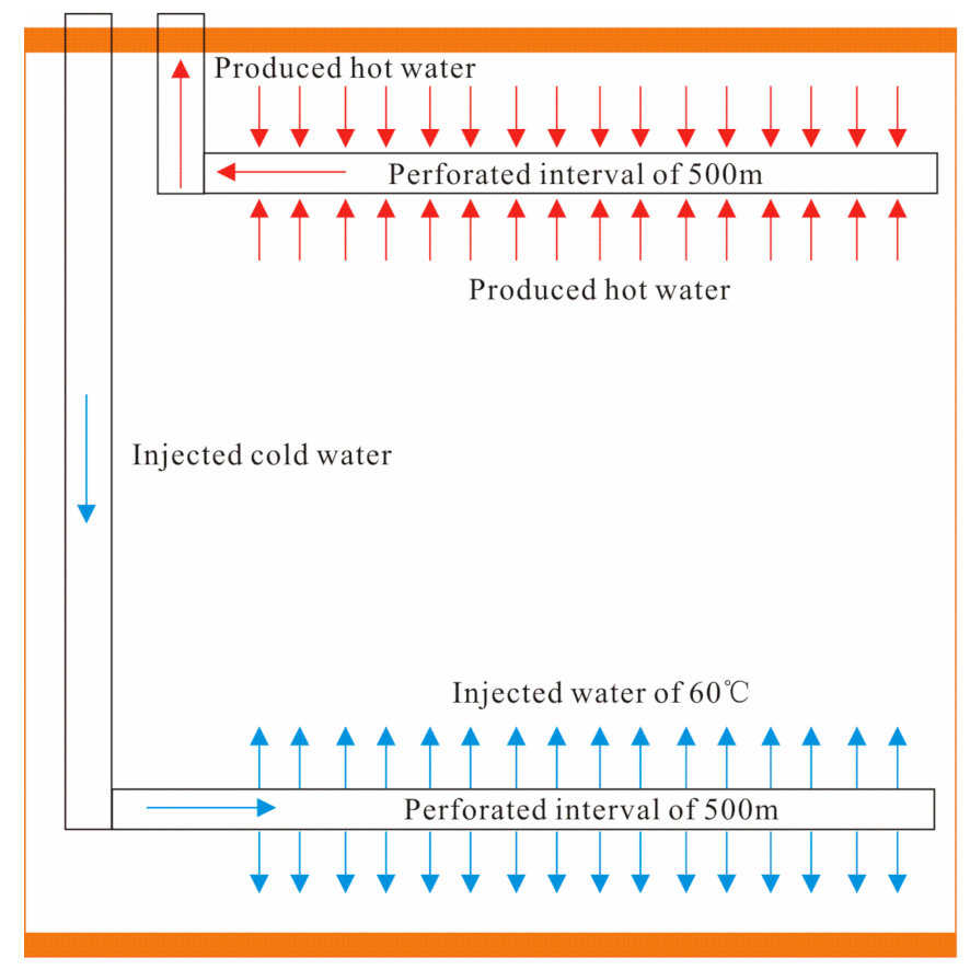
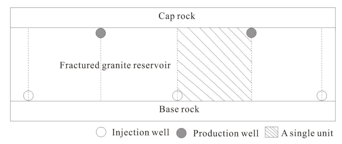
4. Numerical Models and Simulation Approach

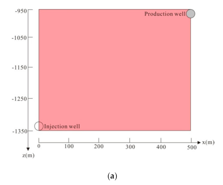
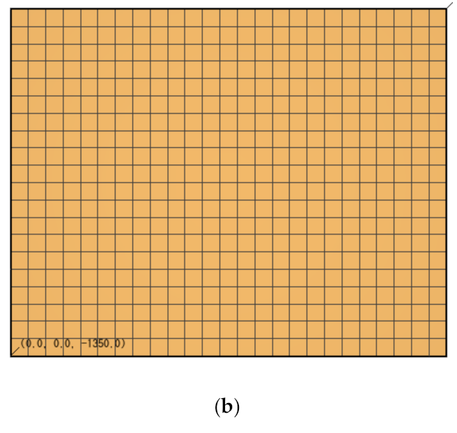
4.1. Domain, Grid and Parameters

In this study, we used the TOUGH2-EOS1 codes to simulate the heat production and electricity generation process [34]. TOUGH2 software is a numerical simulator for nonisothermal flows of multicomponent, multiphase fluids in one-, two- and three-dimensional porous and fractured media. This software used the integral finite difference method to solve the conservation equations of mass, momentum and energy. The accuracy of the software has been proved by comparison with many different analytical and numerical solutions, and thus it has been widely used in geothermal reservoir engineering [34]. The study domain is located in a depth of 950–1350 m, corresponding to the fractured granite reservoir at Yangbajing geothermal field. Water supply from the deep formation and the weak heat conduction between the impermeable cap rock and the permeable reservoir are neglected in this study [23,30]. There are two production wells around the injection well, and the horizontal distance between the injection well and the production well is 500 m, as shown in Figure 2. Because of symmetry, only half of the domain in Figure 2 needs to be simulated, shown as the gray area in Figure 2. Assuming the whole length of the horizontal wells is 500 m, only a 10 m length along the well needs to be simulated, and thus the water production rate of the simulated domain is 50 times that of the 10 m length domain. The length of the simulated domain is 500 m along the x-direction, 10 m along the y-direction and 400 m along the z-direction. If the water production rate of the 10 m length domain is q, then the whole water production rate of the three horizontal well system is Q: Q = q × 50 × 2 = 100 q. For the EPM method, it is uniformly divided into 25 grid blocks along the x-direction, and the width of every grid block is 20 m; there is only one grid block along the y-direction, and the width of this grid block is 10 m; it is uniformly divided into 20 grid blocks along the z-direction, and height of every grid block is 20 m. Therefore the whole two-dimensional system in Figure 3 comprises 25 × 1 × 20 = 500 grid blocks. When the fracture spacing is less than 2–3 m, the assumption of local thermodynamic equilibrium between the water and rock is reasonable, and under this condition, the computation results of the EPM method are in the same levels as those of the MINC method [14]. For the MINC method, we divided each grid block of the EPM method into 5 continua with volume fractions of 0.0060, 0.0663, 0.1325, 0.2651 and 0.5301, respectively. Therefore, the whole system for the MINC method has 25 × 1 × 20 × 5 = 2500 grid blocks. In this study, for the MINC method, we investigated the production performance and efficiency under the condition of fracture spacing of 3, 5, 10, 25, 50, 100, 200 and 300 m [14]. Figure 3 shows the simulated domain and the corresponding grid used in the simulation as stated above. The injection well is located at depth of z = −1330 m, and the production wells are located at depth of z = −970 m. Because the radius of the horizontal well is only rw = 0.10 m, far smaller than the size of the grid block, the well is represented by the grid blocks in which the well is located in the form of source term [34].
Conditions and properties of the simulated domain of the 950–1350 m fractured granite reservoir are shown in Table 1 [30], and other parameters of the rock matrix and fractures can be found in [23]. For the EPM method, there is only one porosity and one permeability; thus, the porosity ϕ and permeability k of the fractured reservoir are determined by Equations (1) and (2), where ϕ m and k m are the porosity and permeability of the rock matrix, respectively, and ϕ f and k f is the porosity and permeability of the fractures, respectively.
ϕ = ϕ m + ϕ f
k = k m + k f

4.2. Boundary and Initial Conditions

The saturated vapor pressure corresponding to 248 °C is 3.84 MPa, which is far lower than the bottomhole pressure at the production well, which is 5.00 Mpa, so water in the wells and reservoir is all kept as liquid [30]. The initial reservoir temperature is 248 °C, and the initial reservoir pressure is P = 0.0089 z 0.4444 ( MPa ) . As stated above, the slight conductive heat exchange between the impermeable cap rock or base rock and the permeable reservoir is neglected, so the boundaries at the top and bottom of the reservoir in Figure 3 are no-flow for mass and heat. Due to symmetry, the left and right boundaries in Figure 3 are also no-flow for mass and heat.

5. Results and Discussion

5.1. The Determination of Water Injection Rate

The injection of cold water through the injection well into the fractured reservoir will increase the pressure at the wells and the reservoir; too high pressure will cause fracture extension and reservoir damage, so the bottomhole injection pressure Pinj must be kept lower than a limit Pmax. Based on the study of [14], in this work we assume the following:
Pinj < Pmax
where Pmax = fPw0; f = 1.2 is the safety factor, which is determined by the actual geological conditions of the reservoir [14]; Pw0 is the initial pressure of the injection wellbore. In this work, the injection well is located at z = −1330 m, and the corresponding initial pressure is Pw0 = 11.39 MPa; thus, Pmax = 13.67 MPa. The production wells are located at z = −970 m, and the corresponding initial pressure is 8.19 MPa; the bottomhole production pressure is kept at P0 = 5.00 MPa to maintain production. The injection temperature is Tinj = 60 °C [14], and the corresponding injection specific enthalpy is about hinj = 261.20 kJ/kg. Based on (3), the maximum water injection rate of the simulated domain is q = 2.0 kg/s, and the whole water injection rate of the three horizontal well system is Q = 100q = 200.0 kg/s.

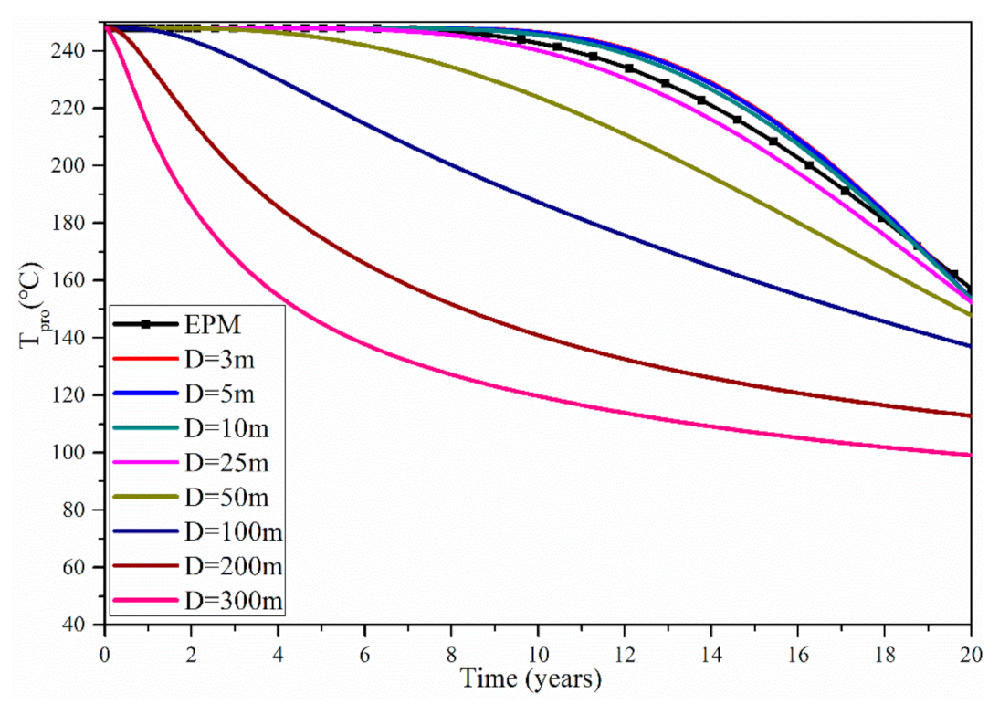
5.2. Production Temperature
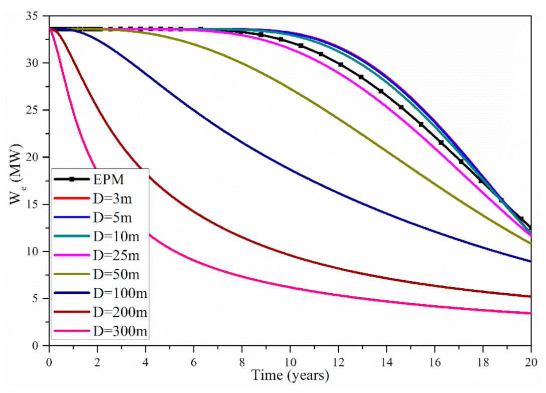
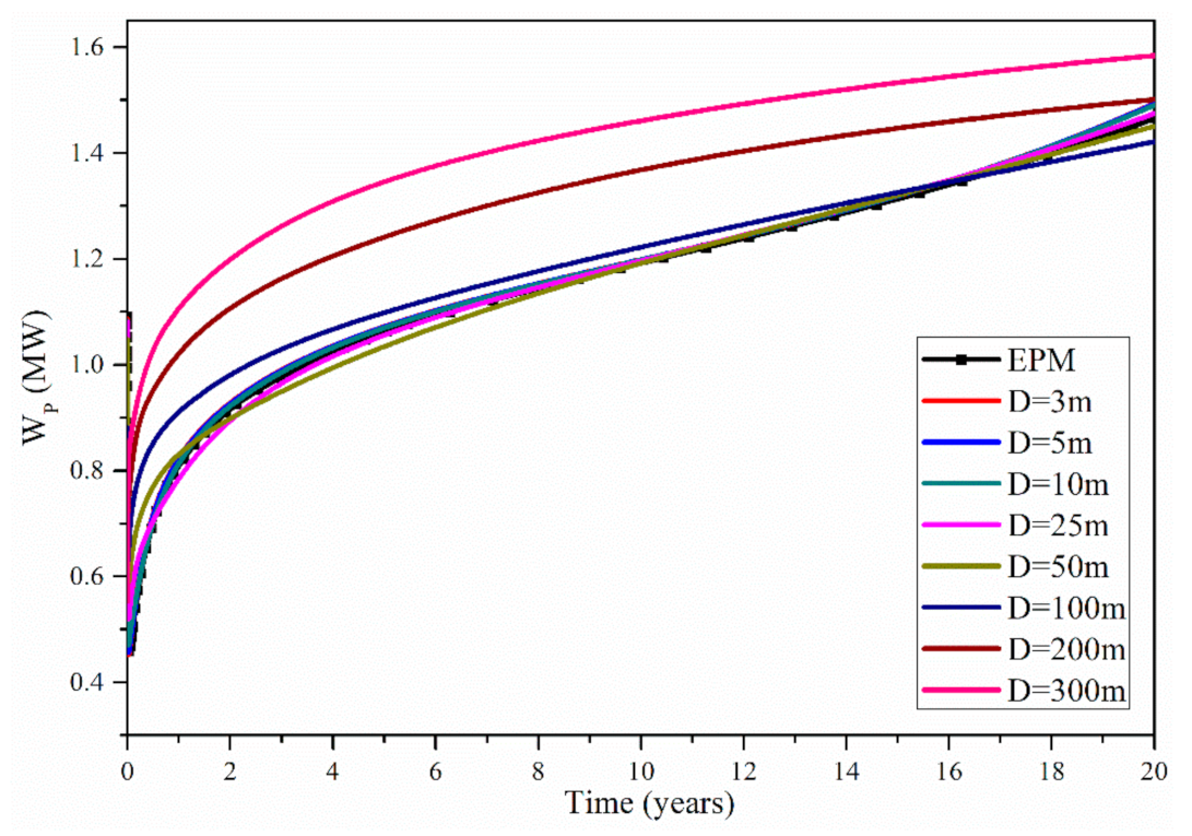
Figure 4 shows the evolution of production temperature Tpro for the EPM method and the MINC method. For the MINC method, the investigated fracture spacings are 3, 5, 10, 25, 50, 100, 200 and 300 m, while the other conditions are the same as those for the EPM method. The corresponding relationships of the porosity and permeability between the EPM method and MINC method are determined by Equations (1) and (2). Figure 4 indicates that when using the EPM method, the Tpro during the 20 years is within 248.00–156.96 °C. Using the MINC method, when the fracture spacing is 3, 5, 10 and 25 m, the Tpro is within 248.00–153.51 °C, 248.00–153.51 °C, 248.00–153.48 °C and 248.00–152.33 °C, respectively. Therefore, when the fracture spacing D is within 3–25 m, the Tpro values found with the EPM method are basically in the same levels as those of the MINC method. When D increases to be 50, 100, 200 and 300 m, the corresponding Tpro during the 20 years is within 248.00–147.82 °C, 248.00–136.99 °C, 248.00–112.82 °C and 248.00–99.11 °C, respectively. Therefore, when fracture spacing is within 25–300 m, with the increase in the fracture spacing, the difference in Tpro between the EPM method and the MINC method gradually increases; thus, when D is larger than 25 m, we should use the MINC method to simulate the fractured reservoirs, and the EPM method is not reasonable under this condition. Besides, Figure 4 shows that with the increase in D, the duration of the stable stage gradually decreases, the duration of the declining stage gradually increases and the declining rate of Tpro during the declining stage gradually increases. This is because higher D effectively reduces the heat transfer area between the water and the rock, and this will obviously decrease the thermal power according to the heat transfer formula of convection and thus decrease the Tpro. This is consistent with results from Sanyal et al. using the DPM method [15].

5.3. Electric Power

The electric power We is calculated by the equation in [14], and the heat rejection temperature of the Yangbajing geothermal power plant is T0 = 9 °C = 282.15 K [25].
Figure 5 shows the evolution of the electric power We of the EPM method and the MINC method. During the 20 years, using the EPM method, the We is within 33.61–12.50 MW. Using the MINC method, when the fracture spacing is 3, 5, 10 and 25 m, the We is within 33.62–11.86 MW, 33.62–11.86 MW, 33.63–11.85 MW and 33.6–11.64 MW, respectively. Therefore when D is within 3–25 m, the difference in We between the EPM method and the MINC method is very small; thus, under this condition, we can use the EPM method to simulate the fractured geothermal reservoirs. When D increases to be 50, 100, 200 and 300 m, the corresponding We during the 20 years is within 33.63–10.82 MW, 33.63–8.93 MW, 33.63–5.22 MW and 33.63–3.44 MW, respectively. Therefore, when D is within 25–300 m, with the increase in D, the difference in We between the EPM method and the MINC method gradually increases; thus, when D is within 25–300 m, it is unreasonable to use the EPM method to model the fractured geothermal reservoirs. With the increase in fracture spacing, the heat conduction in the rock mass becomes predominant and the heat convection in the fracture water becomes secondary. The MINC method can carefully consider the heat conduction in the rock mass; in this method, the pressure and temperature changes in the matrix are controlled locally by the distance from the fractures. Thus, for greater fracture spacing, the MINC method is more suitable. For smaller fracture spacing, the heat convection in the fracture water is predominant and the heat conduction is secondary; thus, both the EPM method and the MINC method are suitable. Besides, Figure 5 also shows that during the stable stage, the We basically remains unchanged with the increase in D; during the declining stage, the rate of decline in We gradually increases with the increase in D. As stated above, this is because higher D obviously reduces the heat transfer area between the rock and water, and this will obviously decrease the thermal power and the electric power [14].

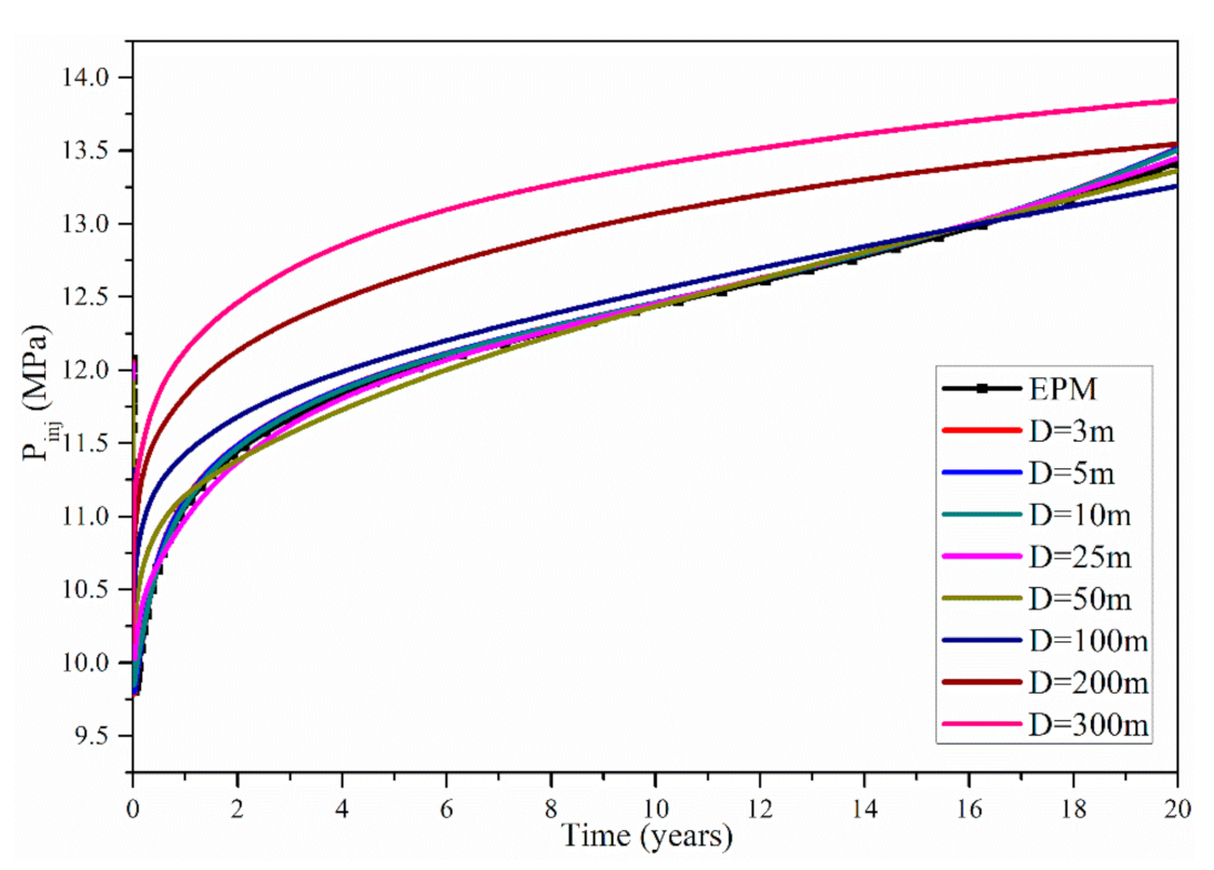
5.4. Injection Pressure

Figure 6 shows the evolution of the injection pressure Pinj of the EPM method and the MINC method. Using the EPM method, during the 20 years, the injection pressure Pinj is within 9.81–13.42 MPa. Using the MINC method, when the fracture spacing is 3, 5, 10 and 25 m, the Pinj is within 9.78–13.52 MPa, 9.80–13.52 MPa, 9.85–13.51 MPa and 10.03–13.45 MPa, respectively. Therefore, when D is within 3–35 m, the results of the EPM method are in the same levels as those of the MINC method, and under this condition, we can use the EPM method to simulate the fractured geothermal reservoirs. However, when D increases to be 50, 100, 200 and 300 m, the corresponding Pinj during the 20 years is within 10.27–13.36 MPa, 10.42–13.26 MPa, 10.36–13.55 MPa and 10.15–13.84 MPa, respectively. Therefore, when D is within 25–300 m, the difference in Pinj between the EPM method and the MINC method increases with the increase in D; thus, under this condition, it is unreasonable to use the EPM method to model the fractured geothermal reservoirs. Besides, Figure 6 shows that the Pinj gradually increases with time. This is because as reservoir temperature gradually decreases, the water temperature in the reservoir also decreases with time, and this causes a gradual increase in water viscosity and an increase in reservoir impedance. This effect has been clearly stated in a previous study from Zeng et al. [14].

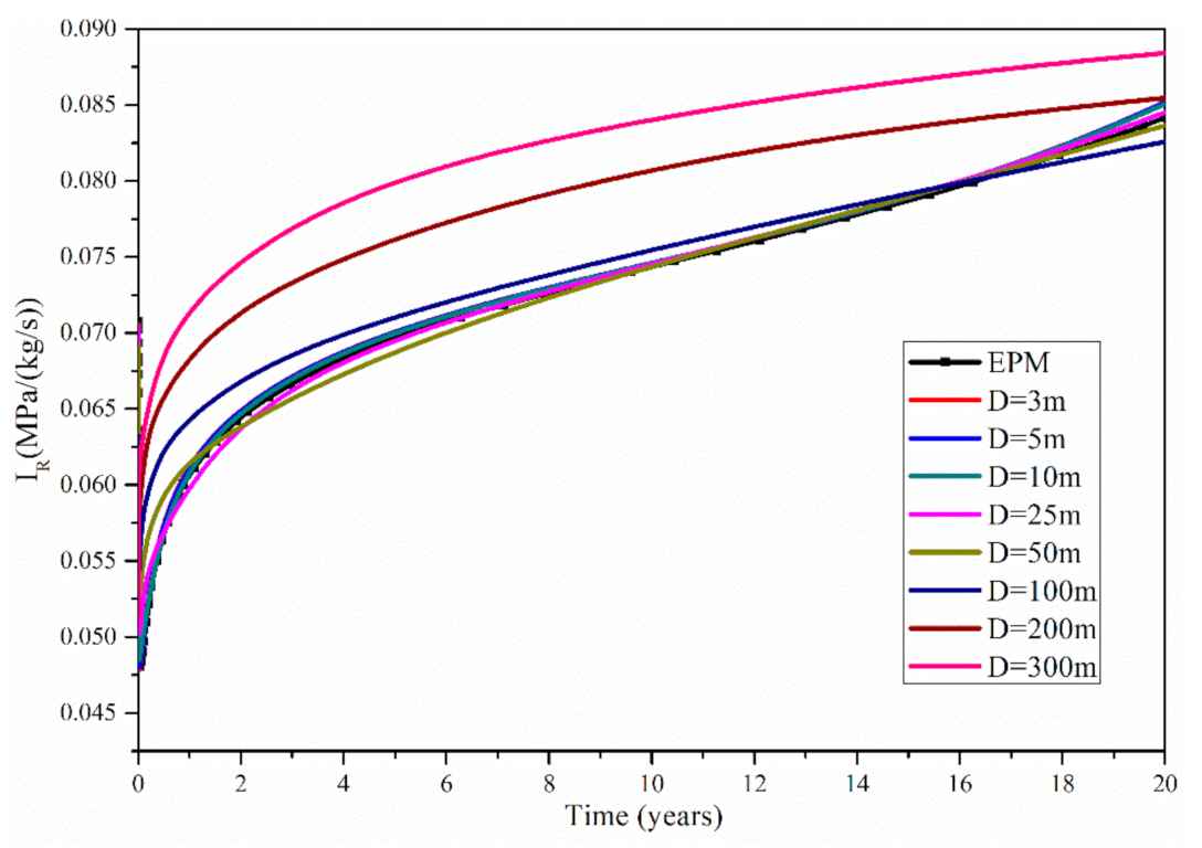
5.5. Reservoir Impedance

The reservoir impedance I R is calculated by the equation in [14]. I R represents the power consumption of the unit production rate for penetrating the fractured reservoir, P pro = P0 = 5.00 MPa is the bottomhole production pressure and q0 = 50q = 100.0 kg/s is the water production rate between the injection well and the production well. Figure 7 shows the evolution of the reservoir impedance I R of the EPM method and the MINC method. Using the EPM method, during the 20 years, the I R is within 0.048–0.084 MPa/(kg/s). Using the MINC method, when the fracture spacing is 3, 5, 10 and 25 m, the I R is within 0.048–0.085 MPa/(kg/s), 0.048–0.085 MPa/(kg/s), 0.049–0.085 MPa/(kg/s) and 0.050–0.085 MPa/(kg/s), respectively. Therefore, when D is within 3–25 m, the results of the EPM method are basically in the same levels as those of the MINC method, and under this condition, we can use the EPM method to model the fractured geothermal reservoirs. However, when D increases to be 50, 100, 200 and 300 m, the corresponding I R during the 20 years is within 0.053–0.084 MPa/(kg/s), 0.05–0.083 MPa/(kg/s), 0.054–0.085 MPa/(kg/s) and 0.051–0.088 MPa/(kg/s), respectively. Therefore when D is within 25–300 m, with the increase in D, the difference in IR between the EPM method and the MINC method gradually increases, and under this condition, it is unreasonable to use the EPM method to model the fractured geothermal reservoirs. Besides, as mentioned above, Figure 7 also shows that during the 20 years the I R gradually increases with time, which is caused by the increase in water viscosity caused by the decline in reservoir temperature [14].

5.6. Pump Power

The internal energy consumption of the pump power can be calculated by the equation in [14]. The water density ρ varies with pressure and temperature, and this will significantly impact the calculation of W p [14]. The average value of the minimum density and maximum density is used for computations in this study [14]. The maximum density is 989.0 kg/m3, and the minimum density is 804.0 kg/m3; thus, the average value of ρ = 896.5 kg/m3 is adopted for calculations. Figure 8 shows the evolution of the pump power W p of the EPM method and the MINC method. Using the EPM method, during the 20 years, the W p is within 0.46–1.47 MW. Using the MINC method, when the fracture spacing is 3, 5, 10 and 25 m, the W p is within 0.45–1.49 MW, 0.46–1.49 MW, 0.47–1.49 MW and 0.52–1.47 MW, respectively. Therefore, when D is within 3–25 m, the results of the EPM method are in the same levels as those of the MINC method; thus, under this condition, the EPM method can be used to model the fractured geothermal reservoirs. However, when D increases to be 50, 100, 200 and 300 m, the corresponding W p during the 20 years is within 0.59–1.45 MW, 0.63–1.42 MW, 0.61–1.50 MW and 0.56–1.58 MW, respectively. Therefore, when D is within 25–300 m, with the increase in D, the difference in W p between the EPM method and the MINC method gradually increases, and under this condition, it is unreasonable to use the EPM method to model the fractured geothermal reservoirs. Besides, Figure 8 also shows that during the 20 years the W p gradually increases with time. Based on the equation of W p in [14], this is caused by the gradual increase in Pinj, and this is in accordance with previous studies [14].

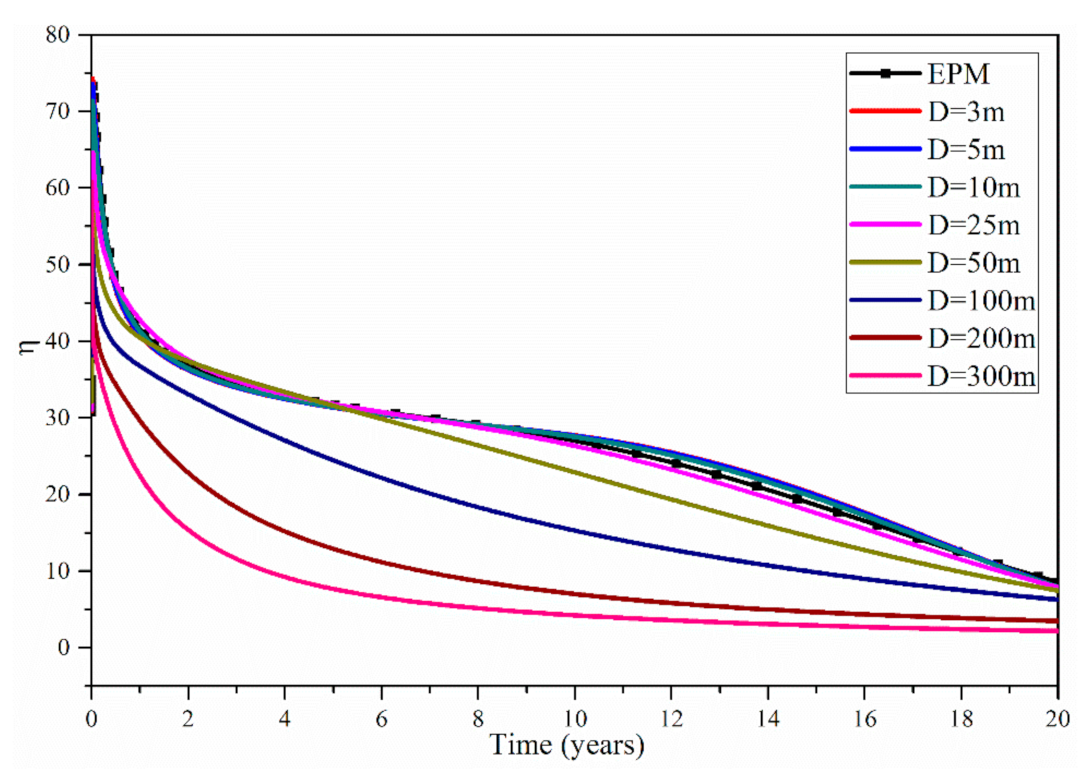
5.7. Energy Efficiency

The energy efficiency η of the system can be calculated by the equation in [14]. As stated above, the average value of the water density of ρ = 896.5 kg/m3 is adopted in the calculation of η. Figure 9 shows the evolution of the energy efficiency η of the EPM method and the MINC method. Using the EPM method, during the 20 years, the η is within 73.28–8.53. Using the MINC method, when the fracture spacing is 3, 5, 10 and 25 m, the η is within 74.30–7.94, 73.59–7.94, 71.33–7.95 and 64.61–7.89, respectively. Therefore, when D is within 3–25 m, the results of the EMP method are in accordance with those of the MINC method; under this condition, we can use the EPM method to simulate the fractured geothermal reservoirs. However, when D increases to be 50, 100, 200 and 300 m, the corresponding η during the 20 years is within 57.08–7.46, 53.33–6.29, 54.80–3.48 and 60.82–2.17, respectively. Therefore, when D is within 25–300 m, with the increase in D, the difference in η between the EPM method and the MINC method gradually increases; under this condition, it is unreasonable to use the EPM method to model the fractured geothermal reservoirs. Besides, Figure 9 also shows that during 20 years the η gradually decreases. Based on the equation of η in [14], this is caused by the gradual decline in Tpro and the gradual increase in Pinj, and this is in accordance with a previous study from Zeng et al. [14].

5.8. Applicable Fracture Spacing of the DPM Method

Because the DPM method considers fracture spacing, fracture porosity and permeability and rock matrix porosity and permeability, the DPM method can be used to model the fluid flow and heat transfer process in a fractured porous medium under all kinds of fracture spacing, just like the MINC method. Sanyal et al. used the DPM method to investigate production performance and efficiency characteristics of the EGS at Desert Peak geothermal field and analyzed the influence of fracture spacing on electricity generation for fracture spacing within 0.33–300 m [15]. The results show that increasing permeability without increasing matrix-to-fracture heat transfer area has little benefit in net generation or heat recovery; an increase in stimulation volume increases generation level without obviously impacting the shape of the generation profile; and the recovery factor can be reasonably correlated with stimulation volume, irrespectively of well geometry, fracture spacing and fracture domain permeability. Because Sanyal et al. discussed the influence of fracture spacing on the heat production performance and efficiency of EGS reservoir in [15], we directly refer to the corresponding conclusions in this study. For more information about the applicable fracture spacing in the DPM method, please refer to [15].

5.9. Limitation of the Model

There are three main limitations of the model in this work. First, the water loss is neglected. In actual EGS reservoirs, the water loss is ever-present, and neglecting water loss will improve the production performance of the EGS. Second, the rock deformation due to pore elasticity and thermal contraction of rocks is neglected. Third, the chemical dissolution and precipitation of rock minerals are neglected. The second and third effects on the production performance of EGSs need further study in the future.

6. Conclusions

In this study, we mainly investigated the influence of the fracture spacing on the electricity generation performance and efficiency for fracturing spacing within 3–300 m by means of numerical simulation, and we discussed the applicable fracture spacing for the EPM method based on the geological data from Yangbajing geothermal field. According to the simulation results, we can draw the following conclusions:
(1)
Under the reference conditions, the applicable fracture spacing for the EPM method is within 3–25 m. Within this range, with the increase in the fracture spacing, the production temperature, electric power, injection pressure, reservoir impedance, pump power and energy efficiency are only very slightly influenced, and the results of the EPM method are in accordance with those of the MINC method.
(2)
When the fracture spacing is larger than 25 m, with the increase in the fracture spacing, the difference in the simulated results between the EPM method and the MINC method gradually increases; under this condition, it is unreasonable to use the EPM method to model the fractured geothermal reservoirs, and the DPM method or the MINC method should be used.
(3)
When the fracture spacing is within 25–300 m, with the increase in the fracture spacing, the heat exchange area between the rock and water gradually decreases; the thermal power and electric power gradually decline; the injection pressure, reservoir impedance and pump power gradually increase; and the energy efficiency gradually decreases.
(4)
The above conclusions are only valid for the current setup, and although it may be possible to transfer the conclusions to other fields, any such generalization should be done with caution.

Author Contributions

Formal analysis, Y.Z.; Methodology, Y.Z. and F.S.; Writing, Y.Z.; Review, H.Z. All authors have read and agreed to the published version of the manuscript.

Funding

The study was financially supported by the GDAS Project of Science and Technology Development (2020GDASYL-20200102020, 2020GDASYL-20200102013, 2020GDASYL-20200301003, 2020GDASYL-20200402003, 2020GDASYL-20200302007, 2019GDASYL-0102002), Guangdong Foundation for Program of Science and Technology Research (2019B121205006, 2019B121201004), the National Natural Science Foundation of China (NSFC: 41930865) and Open Foundation of Key Laboratory of Natural Gas Hydrate, CAS (E0290206). We are also thankful for the support from the Northern Guangdong Soil Environment Observation and Research Station and the Guangdong Engineering Center of Non-point Source Pollution Control.

Acknowledgments

The authors are grateful for the comments by Nengyou Wu at the Qingdao Institute of Marine Geology, China Geological Survey, which significantly improved the manuscript.

Conflicts of Interest

The authors declare no conflict of interest.

Nomenclature

Cpspecific heat capacity, J/(kg·°C)
Dfracture spacing, m
ggravity, 9.80 m/s2
hwell depth, m
h1depth of injection well, m
h2depth of production well, m
hinjinjection specific enthalpy, kJ/kg
h pro production specific enthalpy, kJ/kg
IRreservoir impedance, MPa/(kg/s)
kreservoir permeability, m2
kffracture permeability, m2
kmmatrix permeability, m2
kxintrinsic permeability along x, m2
kyintrinsic permeability along y, m2
kzintrinsic permeability along z, m2
Ppressure, MPa
Pmaxcritical pressure, MPa
P inj injection pressure, MPa
P pro production pressure, MPa
P0bottomhole production pressure, MPa
qwater production rate, kg/s
Qtotal water production rate, kg/s
Ttemperature, °C
T0mean heat rejection temperature, 282.15 K
T pro production temperature, °C
Vvelocity vector, m/s
W p electric power of pump, MW
Weelectric power, MW
x, y, zCartesian coordinates, m
ϕ reservoir porosity
ηenergy efficiency
η p pump efficiency, 80%
ρwater density, kg/m3
μwater dynamic viscosity, Pa·s

References

  1. Tester, J.W.; Livesay, B.; Anderson, B.J.; Moore, M.C.; Bathchelor, A.S.; Nichols, K.; Blackwell, D.D.; Petty, S.; Dipippo, R.; Toksoz, M.N.; et al. The Future of Geothermal Energy: Impact of Enhanced Geothermal Systems (EGS) on the United States in the 21st Century. An Assessment by an MIT-Led Interdisciplinary Panel; Massachusetts Institue of Technology: Cambridge, MA, USA, 2006. [Google Scholar]
  2. Pruess, K. Modelling of geothermal reservoirs: Fundamental processes, computer simulation, and field applications. In Proceedings of the 10th New Zealand Geothermal Workshop, Auckland, New Zealand, 2–4 November 1988. [Google Scholar]
  3. Willis-richards, J.; Wallroth, T. Approaches to the modeling of HDR reservoirs: A review. Geothermics 1995, 24, 307–332. [Google Scholar] [CrossRef]
  4. Hayashi, K.; Willis-Richards, J.; Hopkirk, R.J.; Niibori, Y. Numerical models of HDR geothermal reservoirs–A review of current thinking and progress. Geothermics 1999, 28, 507–518. [Google Scholar] [CrossRef]
  5. Sanyal, S.K.; Butler, S.J.; Swenson, D.; Hardeman, B. Review of the state-of-the-art of numerical simulation of enhanced geothermal system. In Proceedings of the World Geothermal Congress, Kyushu-Tohoku, Japan, 28 May–10 June 2000. [Google Scholar]
  6. O’Sullivan, M.J.; Pruess, K.; Lippmann, M.J. State of the art of geothermal reservoir simulation. Geothermics 2001, 30, 395–429. [Google Scholar] [CrossRef]
  7. Wu, Y.S. On the effective continuum method for modeling multiphase flow, multicomponent transport and heat transfer in fractured rock. In Dynamics of Fluids in Fractured Rock, Geophysical Monograph 122; American Geophysical Union: Washington, DC, USA, 2000; pp. 299–312. [Google Scholar]
  8. Long, J.C.; Remer, J.S.; Wilson, C.R.; Witherspoon, P.A. Porous media equivalents for networks of discontinuous fractures. Water Resour. Res. 1982, 18, 645–658. [Google Scholar] [CrossRef] [Green Version]
  9. Pruess, K.; Faybishenho, B.; Bodvarsson, G.S. Alternative concepts and approaches for modeling flow and transport in thick unsaturated zones of fractured rocks. J. Contam. Hydrol. 1999, 38, 281–322. [Google Scholar] [CrossRef]
  10. Scanlon, B.; Mace, R.E.; Barrett, M.E.; Smith, B. Can we simulate regional groundwater flow in a karst system using equivalent porous media models? Case study, Barton Springs Edwards aquifer, USA. J. Hydrol. 2003, 276, 137–158. [Google Scholar] [CrossRef]
  11. Birdsell, S.; Robinson, B. A three-dimensional model of fluid, heat, and tracer transport in the Fenton Hill hot dry rock reservoir. In Proceedings of the Thirteenth Workshop on Geothermal Reservoir Engineering, Stanford, CA, USA, 19–21 January 1988. [Google Scholar]
  12. Mcdermott, C.I.; Randriamanjatosoa, A.R.; Tenzer, H.; Kolditz, O. Simulation of heat extraction from crystalline rocks: The influence of coupled processes on differential reservoir cooling. Geothermics 2006, 35, 321–344. [Google Scholar] [CrossRef]
  13. Watanabe, N.; Wang, W.Q.; McDermott, C.I.; Taniguchi, T.; Kolditz, O. Uncertainly analysis of thermo-hydro-mechanical coupled processes in heterogeneous porous media. Comput. Mech. 2010, 45, 263–280. [Google Scholar] [CrossRef]
  14. Zeng, Y.C.; Su, Z.; Wu, N.Y. Numerical simulation of heat production potential from hot dry rock by water circulating through two horizontal wells at Desert Peak geothermal field. Energy 2013, 56, 92–107. [Google Scholar] [CrossRef]
  15. Sanyal, S.K.; Butler, S.J. An analysis of power generation prospects from enhanced geothermal systems. In Proceedings of the World Geothermal Congress 2005, Antalya, Turkey, 24–29 April 2005; pp. 1–6. [Google Scholar]
  16. Taron, J.; Elsworth, D.; Min, K.B. Numerical simulation of thermal-hydrologic-mechanical-chemical processes in deformable, fractured porous media. Int. J. Rock Mech. Min. Sci. 2009, 46, 842–854. [Google Scholar] [CrossRef]
  17. Taron, J.; Elsworth, D. Thermal-hydrologic-mechanical-chemical processes in the evolution of engineered geothermal reservoirs. Int. J. Rock Mech. Min. Sci. 2009, 46, 855–864. [Google Scholar] [CrossRef]
  18. Gelet, R.; Loret, B.; Khalili, N. A thermal-hydro-mechanical coupled model in local thermal non-equilibrium for fractured HDR reservoir with double porosity. J. Geophys. Res. 2012, 117, 1–23. [Google Scholar] [CrossRef]
  19. Gelet, R.; Loret, B.; Khalili, N. Thermal recovery from a fractured medium in local thermal non-equilibrium. Int. J. Numer. Anal. Method Geomech. 2013, 37, 2471–2501. [Google Scholar] [CrossRef] [Green Version]
  20. Pruess, K. Enhanced geothermal system (EGS) using CO2 as working fluid–A novel approach for generating renewable energy with simultaneous sequestration of carbon. Geothermics 2006, 35, 351–367. [Google Scholar] [CrossRef] [Green Version]
  21. Pruess, K. On production behavior of enhanced geothermal systems with CO2 as working fluid. Energy Convers. Manag. 2008, 49, 1446–1454. [Google Scholar] [CrossRef] [Green Version]
  22. Spycher, N.; Pruess, K. A phase-partitioning model for CO2-brine mixtures at elevated temperatures and pressures: Application to CO2-enhanced geothermal systems. Transp. Porous Media 2010, 82, 173–196. [Google Scholar] [CrossRef] [Green Version]
  23. Borgia, A.; Pruess, K.; Kneafsey, T.J.; Oldenburg, C.M.; Pan, L. Numerical simulation of salt precipitation in the fractures of a CO2-enhanced geothermal system. Geothermics 2012, 44, 13–22. [Google Scholar] [CrossRef]
  24. Sun, Z.X.; Jiang, C.Y.; Wang, X.G.; Zhuo, W.; Lei, Q.H. Combined effects of thermal perturbation and in-situ stress on heat transfer in fractured geothermal reservoirs. Rock Mech. Rock Eng. 2021, 54, 2165–2181. [Google Scholar] [CrossRef]
  25. Sun, Z.X.; Jiang, C.Y.; Wang, X.G.; Lei, Q.H.; Jourde, H. Joint influence of in-situ stress and fracture network geometry on heat transfer in fractured geothermal reservoirs. Int. J. Heat Mass Transfer 2020, 149, 119216. [Google Scholar] [CrossRef]
  26. Davarpanah, A.; Mirshekari, B. Experimental investigation and mathematical modeling of gas diffusivity by carbon dioxide and methane kinetic adsorption. Ind. Eng. Chem. Res. 2019, 58, 27. [Google Scholar] [CrossRef]
  27. Davarpanah, A.; Shirmohammadi, R.; Mirshekari, B.; Aslani, A. Analysis of hydraulic fracturing techniques: Hybrid fuzzy approaches. Arab. J. Geosci. 2019, 12, 402. [Google Scholar] [CrossRef]
  28. Hu, X.; Xie, J.; Cai, W.C.; Wang, R.; Davarpanah, A. Thermodynamic effects of cycling carbon dioxide injectivity in shale reservoirs. J. Pet. Sci. Eng. 2020, 195, 107717. [Google Scholar] [CrossRef]
  29. Robinson, B.A.; Jones, G.F. A tracer-based model for heat transfer in a hot dry rock reservoir. In Geothermal Resources Council Annual Meeting; Los Alamos National Lab.: Sparks, NV, USA, 1987. [Google Scholar]
  30. Zeng, Y.C.; Wu, N.Y.; Su, Z.; Hu, J. Numerical simulation of electricity generation potential from fractured granite reservoir through a single horizontal well at Yangbajing geothermal field. Energy 2014, 65, 472–487. [Google Scholar] [CrossRef]
  31. Fan, X. Conceptual Model and Assessment of the Yangbajing Geothermal Field, Tibet, China; Geothermal Training Programme, Orkusrofnun, Grensásvegur: Reykjavik, Iceland, 2002; Number 5. [Google Scholar]
  32. Dor, J.; Zhao, P. Characteristics and genesis of the Yangbajing geothermal field, Tibet. In Proceedings of the World Geothermal Congress 2000, Kyushu-Tohoku, Japan, 28 May–10 June 2000; pp. 1083–1088. [Google Scholar]
  33. Zhou, Z.F. Theory on Dynamics of Fluids in Fractured Medium; Higher Education Press: Beijing, China, 2006. (In Chinese) [Google Scholar]
  34. Pruess, K.; Oldenburg, C.; Moridis, G. TOUGH2 User’s Guide, Version 2.0; Lawrence Berkeley National Laboratory: Berkeley, CA, USA, 1999.
  35. Pruess, K. Brief Guide to the MINC-Method for Modeling Flow and Transport in Fractured Media; Lawrence Berkeley National Laboratory: Berkeley, CA, USA, 1992.
  36. Pruess, K. Minc-a Mesh Generator for Flow Simulations in Fractured Reservoirs; Lawrence Berkeley National Laboratory: Berkeley, CA, USA, 1983.
  37. Zeng, Y.C.; Zhan, J.M.; Wu, N.Y.; Luo, Y.Y.; Cai, W.H. Numerical investigation of electricity generation potential from fractured granite reservoir through a single vertical well at Yangbajing geothermal field. Energy 2016, 114, 24–39. [Google Scholar] [CrossRef]
  38. Zeng, Y.; Zhan, J.; Wu, N.; Luo, Y.; Cai, W. Numerical investigation of electricity generation potential from fractured granite reservoir by water circulating through three horizontal wells at Yangbajing geothermal field. Appl. Therm. Eng. 2016, 104, 1–15. [Google Scholar] [CrossRef]
  39. Zeng, Y.C.; Zhan, J.M.; Wu, N.Y.; Luo, Y.Y.; Cai, W.H. Numerical simulation of electricity generation potential from fractured granite reservoir through vertical wells at Yangbajing geothermal field. Energy 2016, 103, 290–304. [Google Scholar] [CrossRef]
Figure 1. Schematic of a conceptual horizontal well enhanced geothermal system in hot rock.
Processes 09 01020 g001
Figure 2. Well arrangement of the 950–1350 m fractured granite reservoir.
Processes 09 01020 g002
Figure 3. A schematic of (a) the fractured reservoir at well ZK4001 and (b) the corresponding grid.
Processes 09 01020 g003aProcesses 09 01020 g003b
Figure 4. Evolution of production temperature of the EPM method and the MINC method.
Processes 09 01020 g004
Figure 5. Evolution of the electric power of the EPM method and the MINC method.
Processes 09 01020 g005
Figure 6. Evolution of the injection pressure of the EPM method and the MINC method.
Processes 09 01020 g006
Figure 7. Evolution of the reservoir impedance of the EPM method and the MINC method.
Processes 09 01020 g007
Figure 8. Evolution of the pump power of the EPM method and the MINC method.
Processes 09 01020 g008
Figure 9. Evolution of the energy efficiency of the EPM method and the MINC method.
Processes 09 01020 g009
Table 1. The 950–1350 m reservoir properties and conditions at well ZK4001 [30].
ParameterValue
Rock thermal conductivity2.50 W/(m·K)
Rock specific heat1000 J/(kg·K)
Rock density2650 kg/m3
Reservoir height400 m
Reservoir length (simulated domain)500 m
Reservoir width (simulated domain)10 m
Rock matrix porosity10%
Rock matrix permeability2 × 10−18 m2
Fracture porosity0.1%
Fracture permeability50 × 10−15 m2
Water production rate (simulated domain) q2.0 kg/s
Bottomhole production pressure P05.00 MPa
Productivity index PI5.0 × 10−12 m3
Injection   specific   enthalpy   h inj 261.20 kJ/kg (about 60 ℃)
Initial temperature248 ℃
Initial pressure P = 0.0089 z 0.4444 ( MPa )
Publisher’s Note: MDPI stays neutral with regard to jurisdictional claims in published maps and institutional affiliations.

