1. Introduction
Coalbed methane (CBM) occurs in coal, and its main component is methane, so it is an important energy resource which can be used as an effective fuel supplement in China. In the process of coal mining, CBM usually needs to be pre-pumped by water ring vacuum pumps as a by-product to prevent gas explosions and outbursts. Like coal, oil, and natural gas, CBM is a non-renewable resource [
1]. The world’s CBM reserves are about 2.4 ×10
14 cubic meters [
2], and can be a reliable supplement to conventional natural gas resources, as the share of natural gas in the world’s energy mix is rapidly increasing [
3,
4,
5].
The utilization rate of coalbed methane extracted from underground coal mines is low, because coalbed methane inhales a large amount of air during the negative pressure extraction process, which is low in concentration, difficult to use, heavy in safety guarantee pressure, and poor in economy. A large quantity of low-concentration coalbed methane is released into the atmosphere, causing a serious waste of fuel resources. In addition, coalbed methane is also a greenhouse gas, which can bring serious greenhouse effects to the environment [
6,
7], and it has a greater ability to destroy the atmospheric ozone layer [
8]. Therefore, the utilization of methane in low concentration coalbed methane has the dual significance of energy saving and environmental protection [
9].
The main methods of the purification and utilization of CBM are the membrane separation [
10], pressure swing adsorption [
11], and low temperature distillation methods [
12], as well as the hydrate process [
13]. Among them, the low-temperature distillation method can remove nitrogen, oxygen, and other impurities completely, and concentrate low concentration coalbed methane. Following which, CH
4 is extracted from the coalbed methane and liquefied into a liquefied natural gas (LNG) product. After liquefaction, the volume will be reduced to 1/600 [
14], which is convenient for transportation and can make full use of clean fuel resources.
The author’s research group has studied technology for the cryogenic liquefaction of low concentration coalbed methane, and has successively established a pilot plant and demonstration project for LNG production from low-concentration coalbed methane. The core equipment of low concentration coalbed methane cryogenic liquefaction technology is the liquefaction cold box [
15]. LNG products are mainly produced at the bottom of the distillation column in this cold box. The gas–liquid phase in the column is always in the process of temperature and component migration, and a new equilibrium needs to be established after each migration, so it is very important to control the parameters of the distillation process [
16]. During the operation process, it is difficult to control the temperature in the distillation column. In the actual operation process, there are often differences between the measured temperature and the theoretical value. If the control is not good, the temperature drift phenomenon will occur, which will seriously affect the separation effect of coalbed methane, and a large quantity of methane will volatilize from the top of the rectification column into the tail gas and be discharged into the atmosphere. The methane recovery rate is low and the LNG output is greatly reduced. If the temperature value is controlled too low, the purity of the LNG products will be affected. Products with substandard purity will not be able to pass into the storage tank due to excessive oxygen content, and they will inevitably escape from the top of the distillation column under the effect of the pressure difference of the distillation column. In this paper, the effect of the distillation column operating temperature on the performance of the liquefaction cold box is investigated, and the research results have practical guiding significance for the determination of the operating parameters of cryogenic liquefaction cold boxes containing oxygen coalbed methane, and the optimization of the process package.
2. Experimental Device
The liquefaction process of low concentration CBM mainly includes the compression, purification, drying, liquefaction, and separation processes [
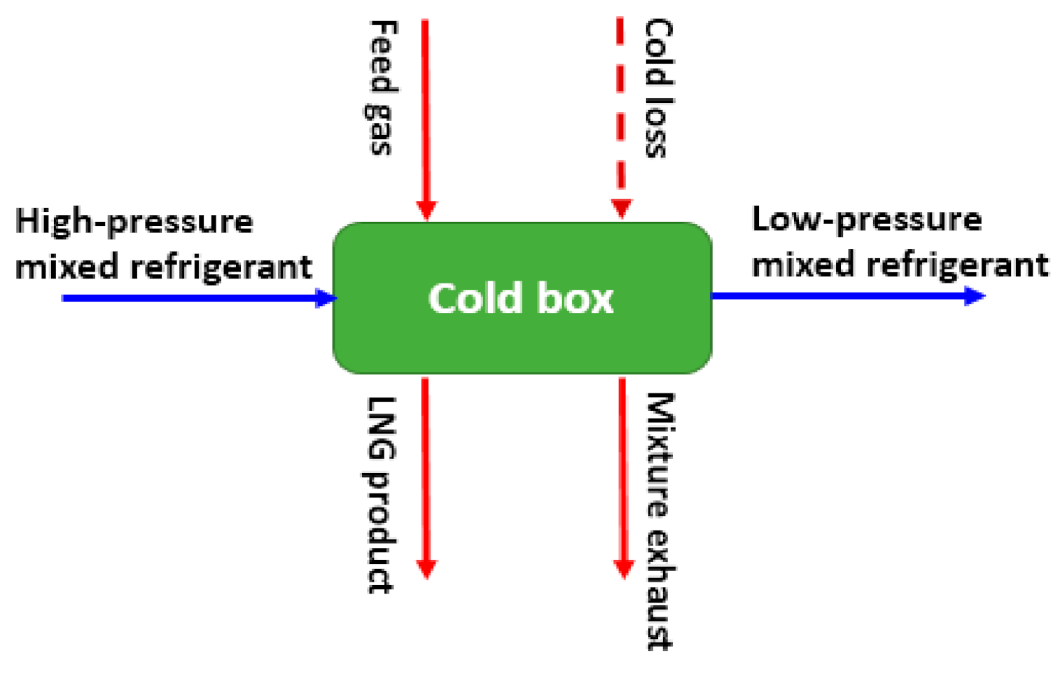
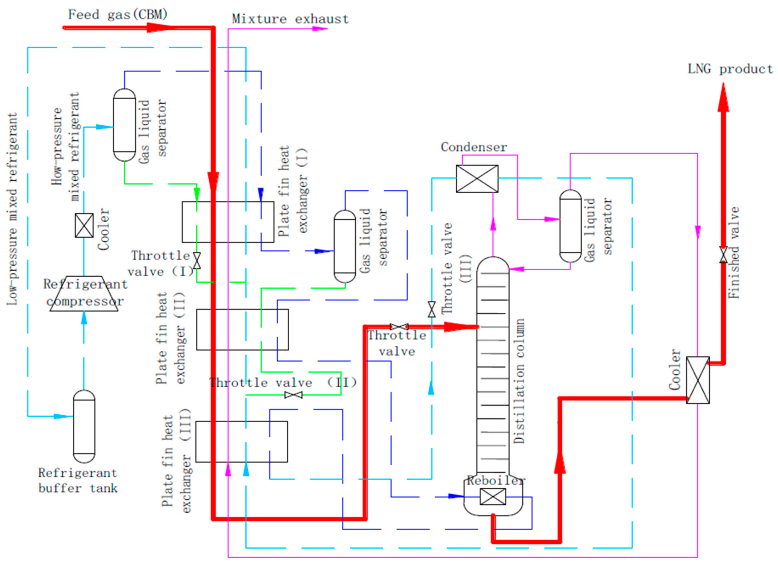
17], where the liquefaction and separation process occur in a cryogenic environment, and the implementation site of the process is a liquefaction cold box. The liquefaction cold box and its process flow, as shown in
Figure 1 and
Figure 2, mainly include a plate fin heat exchanger [
18], throttle valve, gas liquid separator, distillation column, etc.
The purified oxygen-bearing coalbed gas is removed from the CO
2 and acidic gases such as hydrogen sulfide before reaching distillation column (the main component of the absorption liquid is methyldiethanolamine), and the water in it is been deeply removed by molecular sieve. A mixture of oxygen, nitrogen and methane then enters the plate fin heat exchanger (I, II, III) to cool down. The heat exchanger group has two channels of CBM and mixed coolant [
19]. A refrigerant provides cooling capacity for the CBM through a plate fin heat exchanger set and the distillation column top condenser, of which the cooling capacity of the heat exchanger is mainly used to pre-cool the CBM to −172 °C, and the cooling capacity of the condenser is mainly used for separation, so as to condense as much methane as possible into a tail gas on the top of the distillation column.
The principle of low concentration coalbed methane separation in a distillation column is as follows: the substances at the bottom of the column are mainly methane, accompanied by trace amounts of oxygen, nitrogen, and other components. In the process of heating, the oxygen, nitrogen, and other components with high saturated vapor pressure are evaporated into a gas, and escape upward. The substances in the condenser at the top of the column are mainly nitrogen and oxygen. During the cooling process, a small amount of methane is condensed and returned to the distillation column as a low saturated vapor pressure component. After the low-concentration CBM is pre-cooled to −172 °C in the plate fin heat exchanger group, it becomes a gas–liquid two-phase state. After entering the distillation column through the throttle valve, the gas phase volatilizes upward and the liquid phase drops downward. The gas–liquid phase exchange facilitates a transfer of matter and energy between the two phases. The downward-flowing liquid phase is heated by the upward-evaporating gas phase, and the components with a high saturated vapor pressure (oxygen and nitrogen) are evaporated into the gas phase. The upward-evaporating gas phase is cooled, and the less volatile component (methane) is condensed. As a result, the tail gas from the top of the column contains little methane, while the bottom of the distillation column produces a LNG of 99.5% purity.
3. Experimental Methods
After the operation pressure of the distillation column is determined, the main control parameter is the temperature of the distillation column, and its influence on the liquefaction performance is follows: the temperature at the top of the column affects the recovery rate of the methane, and the temperature at the bottom of the column affects the purity of the LNG products. The design value of the feed gas flow of this experimental device is 200 m
3/h, and the mole fraction of the feed gas was:
φ(CH
4) = 0.40,
φ(N
2) = 0.4753,
φ(O
2) = 0.1247. During the experiment, a mixed refrigerant was used, and the mole fraction was
φ(N
2) = 0.366,
φ(CH
4) = 0.31,
φ(C
2H
4) = 0.158,
φ(C
3H
8) = 0.025,
φ(C
4H
10) = 0.082,
φ(C
5H
12) = 0.057. Theoretically, the operating pressure of the distillation column has great influence on the liquefaction performance and energy consumption of the device [
20], but due to the oxygen in coal bed methane, this experiment studied methods of the compression, purification, liquefaction, and separation process at the explosion limit. The finalized operating pressure of the distillation column was 0.32 MPa (absolute pressure), the pressure signal feedback to the nitrogen–oxygen regulator on the tail gas channel operated the opening of the valve at the top of the column so as to ensure the stability of the operating pressure of the distillation column. The number of trays in the design of the distillation column was 32 (including the condenser and reboiler), and the feeding position was the 10th tray from the top. In the actual processing, regular packing was used instead of trays, with an inner diameter of 253 mm and a packing layer height of 7.2 m.
During the experiment, the feed gas flow was adjusted to 150–250 m
3/h, and the methane concentration (mole fraction, the same below) was maintained at 30–45%. The influence of the variation of the feed gas flow rate and methane concentration on the separation performance of the distillation column is explained in detail by the experimental method [
15]. During the experiment, due to the unstable flow rate of the feed gas and the methane concentration, the purity of the LNG products often changed. Using timely adjustments to the mole fraction of each component in the mixed refrigerant and adjusting the refrigeration capacity, the methane content at the bottom of the distillation column was kept above 99% as best as possible. However, if the flow rate and methane concentration of the feed gas were far from the design value, the purity of LNG products could not be maintained above 99%, or even 80%. As the impurity of the product mainly consisted of oxygen, in order to ensure the safety of the storage tank, the cut-off valve on the LNG pipeline entering the storage tank acts immediately to prevent low-purity LNG products from entering the storage tank, thus ensuring the quality of LNG products. The methane content at the bottom of the distillation column (i.e., the purity of LNG) and the methane content in the tail gas at the top of the distillation column were measured using an online chromatograph, and methane recovery was calculated as follows:
where
is the methane recovery rate of the device;
is the flow rate of the feed gas, m
3/h;
is the flow rate of the tail gas at the top of the distillation column, m
3/h;
is the methane content of the feed gas, and
is the methane content of the tail gas. The flow rate of the feed and tail gases were measured using an orifice flowmeter. The temperature at the top and bottom of the distillation column was measured by thermal resistance because it was in a cryogenic environment.
In the process of theoretical analysis, it was necessary to calculate the bubble point and dew point temperatures of the top and bottom of the distillation column, which involved calculation of the physical properties of three components. According to the theory of vapor-liquid equilibrium in engineering thermodynamics, appropriate temperatures should be found for the calculation of bubble point and dew point temperatures, and Equations (2) and (3) should be established, respectively:
where
is to calculate the mole fraction of each component (methane, nitrogen, oxygen) of the mixed liquid at the state point; and
is the gas–liquid equilibrium constant of each component, which is related to the temperature and can be calculated as follows:
where
is the activity coefficient of each component in the liquid phase;
is the fugacity coefficient of each component under saturation pressure;
is the saturated vapor pressure of each component;
is the absolute pressure under the operation state, with 0.319 MPa at the top of the distillation column, and 0.32 MPa at the bottom of the column. In Equation (4), the activity coefficient, fugacity coefficient, and saturated vapor pressure are all functions of temperature, which are calculated by the gas state equation. Therefore, the calculation of the bubble point and dew point temperatures adopts the Newton iteration method and is solved by computer programming.
4. Analysis of Experimental Results
The temperature of the distillation column has a sensitive control effect on evaporation and condensation in the column, and thus has an important influence on the purity of the LNG products and the recovery of methane. In the experiment, by adjusting the opening of throttle valves I, II, and III (
Figure 1), the flow distribution of different components of the refrigerant in each temperature section of the mixed refrigerant channel in the liquefaction cold box was controlled, so as to accurately adjust the temperature at the top and bottom of the distillation column. During the operation, in order to ensure a stable state in the column, the operation of the throttle valve should be slow, and its opening (in percentage) should not be adjusted more than 1% each time. After adjustment, we waited for the cold box to establish a new balance, observed the temperature parameters at key points in the cold box, and recorded the feed gas flow, product oxygen content, nitrogen-oxygen tail gas flow, and methane content of the tail gas after the temperature was stable, so as to calculate the purity of the LNG products and the recovery rate of the methane. Based on the experimental results, the influence of the temperature at the top of the distillation column on methane recovery and of the temperature at the bottom of the column on the purity of the LNG products were measured, respectively, as shown in
Figure 3 and
Figure 4.
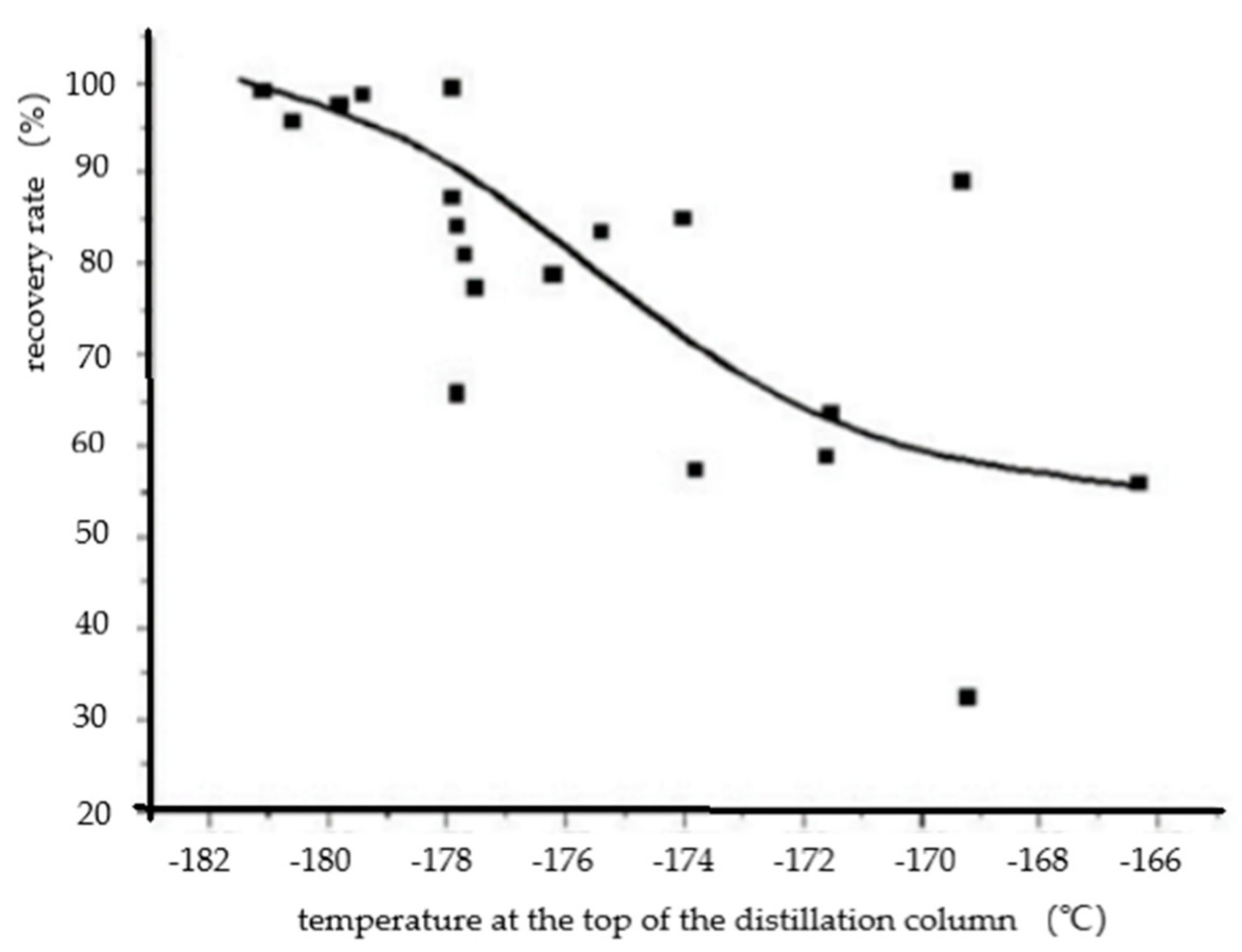
It can be seen from
Figure 3 that the recovery rate of methane gradually decreased with the increase of the temperature at the top of the distillation column. When the temperature at the top of the column rose to −178 °C, the methane recovery rate dropped sharply below 90%. When it continued to rise to −174 °C, the yield failed even to reach 70% (there are some outliers in
Figure 3), resulting in a serious waste of the target components of the feed gas.
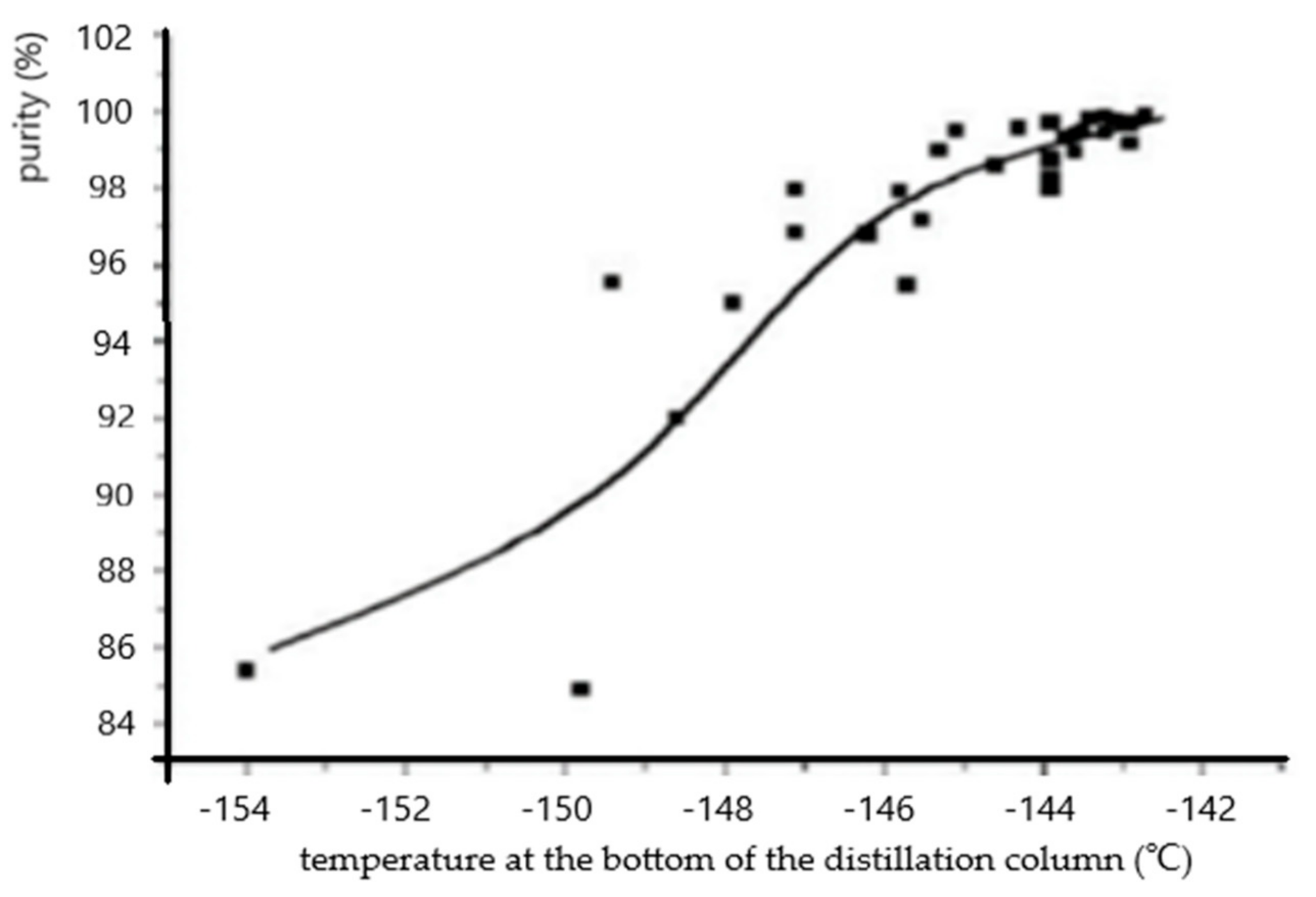
Figure 4 demonstrates that the purity of the LNG products increased with the increase of the temperature at the bottom of the distillation column from −154 °C to −142.7 °C. When the temperature at the bottom of the distillation column was higher than −143.5 °C and the purity of the liquid at the bottom of the column could reach the standard, it could be safely stored as LNG products. In the experiment, it was also found that a higher temperature of the distillation column was not the better. When the temperature was higher than −140 °C, the components at the bottom of the column often drifted and the purity may not have reached the standard (there are also some outliers in
Figure 4). In order to ensure the safety of LNG storage tank, oxygen content in the product should not exceed the standard, and the temperature at the bottom of the distillation column should be controlled at −143 °C.
The content of methane in the nitrogen and oxygen tail gas at the top of the distillation column was determined by the refrigerating capacity provided by the refrigerant to the condenser in the low temperature zone. The greater the amount of refrigerating capacity provided by the mixture, the lower the temperature was at the top of the distillation column, and the more conducive the condensation of the trace methane was in the tail gas, thus reducing the amount of methane carried away and discharged into the atmosphere and improving the recovery rate. Generally, the temperature at the top of the distillation column was set between the bubble point and the dew point temperatures of the components at the top of the column, and the highest temperature was not higher than the dew point temperature. By theoretical calculation, when the molar fraction of each component at the top of the distillation column was
φ(CH
4) = 0.00497,
φ(N
2) = 0.7984,
φ(O
2) = 0.1966, and the absolute pressure was 0.319 MPa, the dew point temperature was −180.03 °C, and the bubble point temperature was −182.753 °C. The higher the methane content was, the higher the dew point temperature and bubble point temperature were. When the temperature was higher than that of the dew point at the top of the distillation column where methane begins to dewdrop, the methane could be condensed into the reflux and was carried away. In this experiment, when the temperature at the top of the distillation column was higher than −178 °C, the methane recovery rate dropped sharply, which is consistent with the calculated value. The trend line in
Figure 3 describes changes to the methane recovery rate in the distillation column based on the top temperature, which can guide operators to adjust the temperature of the distillation column as soon as possible after the parameters of the distillation column change, so as to ensure a high methane recovery rate.
Evaporation at the bottom of the distillation column was used to determine the evaporation temperatures of the trace nitrogen and oxygen components at the bottom of the distillation column, the oxygen content at the bottom of the column, and the product purity [
21]. The bottom of the distillation column was heated with relatively high temperature gaseous refrigerant by plate fin heat exchanger Ⅱ. The heat exchange temperature difference was about 19–21 °C. If the evaporation capacity wsa insufficient and the temperature at the bottom of the distillation column was low, the nitrogen and oxygen components in the column kettle could be fully evaporated, and a larger proportion of nitrogen and oxygen components were mixed into the products, thus reducing the purity of the LNG products produced. The temperature at the bottom of the distillation column was set between the bubble and the dew points of the component at the bottom of the column, and the lowest temperature was not lower than the bubble point. After theoretical calculation, when the bottom of the column produced, the mole fraction of each component was
φ(CH
4) = 0.993,
φ(O
2) = 0.007,
φ(N
2) ≈ 0, at an absolute pressure of 0.32 MPa, and its dew point temperature and bubble point temperature were, respectively, −145.526 °C and −146.016 °C. In theory, when the temperature was lower than −146.016 °C, the oxygen in the liquid at the bottom of the distillation column would be a condensate. Unable to fully evaporate, the oxygen content at the bottom of the column would increase, and the purity would decrease. In this experiment, only when the temperature at the bottom of the distillation column was generally controlled above −145 °C could the purity reach the standard. The temperature at the bottom of the column is required to be higher than the theoretical value due to the high pressure, or else the temperature measuring point sensor would be too close to the heat transfer surface of the reboiler, which would make it wrongly display a higher temperature. Compared with oxygen and methane, the saturated vapor pressure of nitrogen was the highest, so the impurities in the bottom product of the distillation column were determined to be only oxygen and no nitrogen.
The purity of the product is related to the safety of the LNG storage tank. The trend line in
Figure 4 describes changes to the purity of product at the bottom of the distillation column based on the temperature at the bottom of the column, which can guide operators to adjust as soon as possible after the parameters of the distillation column change, so as to ensure that the LNG product does not contain oxygen.
We need to discuss the reasons for the outliers in
Figure 3 and
Figure 4. The device is a small experimental device, which was small in scale and limited by investment. We could select centrifugal, labyrinth, or other expensive imported compressors with good sealing performance as the mixed refrigerant compressor in refrigeration cycle. Instead, an ordinary domestic piston compressor was selected. As leakage of the mixed refrigerant during operation would be serious, the operator must constantly manually replenish the refrigerant in order to maintain the working pressure and refrigerating capacity of the refrigeration process. In the process of operation, each component of the mixed refrigerant was supplemented separately. Thus, the components of the refrigerant could be mixed immediately after replenishment, and the refrigerant group changed in a leaping manner. The heat exchange balance in the cold box and the gas–liquid mass transfer balance in the distillation column were broken instantly. In addition, the data measured by the chromatographic analyzer of the mixed refrigerant were delayed, which inevitably made the supplement amount and operating pressure deviate from the design parameters. At this point, heat and mass transfer inside cold box need to strike a balance, resulting in extremely low product purity and recovery.
5. Technology Optimization
Through the above experiments, the following conclusions can be drawn: the heat load of the reboiler of the distillation column and the cold load of the condenser are provided by the same refrigerant fluid, and their correlation is very strong. The correlation is mainly shown because the temperature at the bottom of distillation column needed to be increased to improve the purity of the LNG. That is, the heating capacity of the liquid at the bottom of the distillation column needed to be increased by changing the flow rate of the liquid, but this interfered with the condensation of methane at the top of the distillation column, thus reducing the recovery rate of the methane. Similarly, to improve the recovery rate of methane, the temperature at the top of the column needed to be reduced, but this also interfered with the evaporation of the nitrogen and oxygen components at the bottom of the column and reduced the purity of the LNG products. The following three measures can be adopted in the industrial scale-up design of a of low concentration coalbed methane cryogenic liquefaction plant:
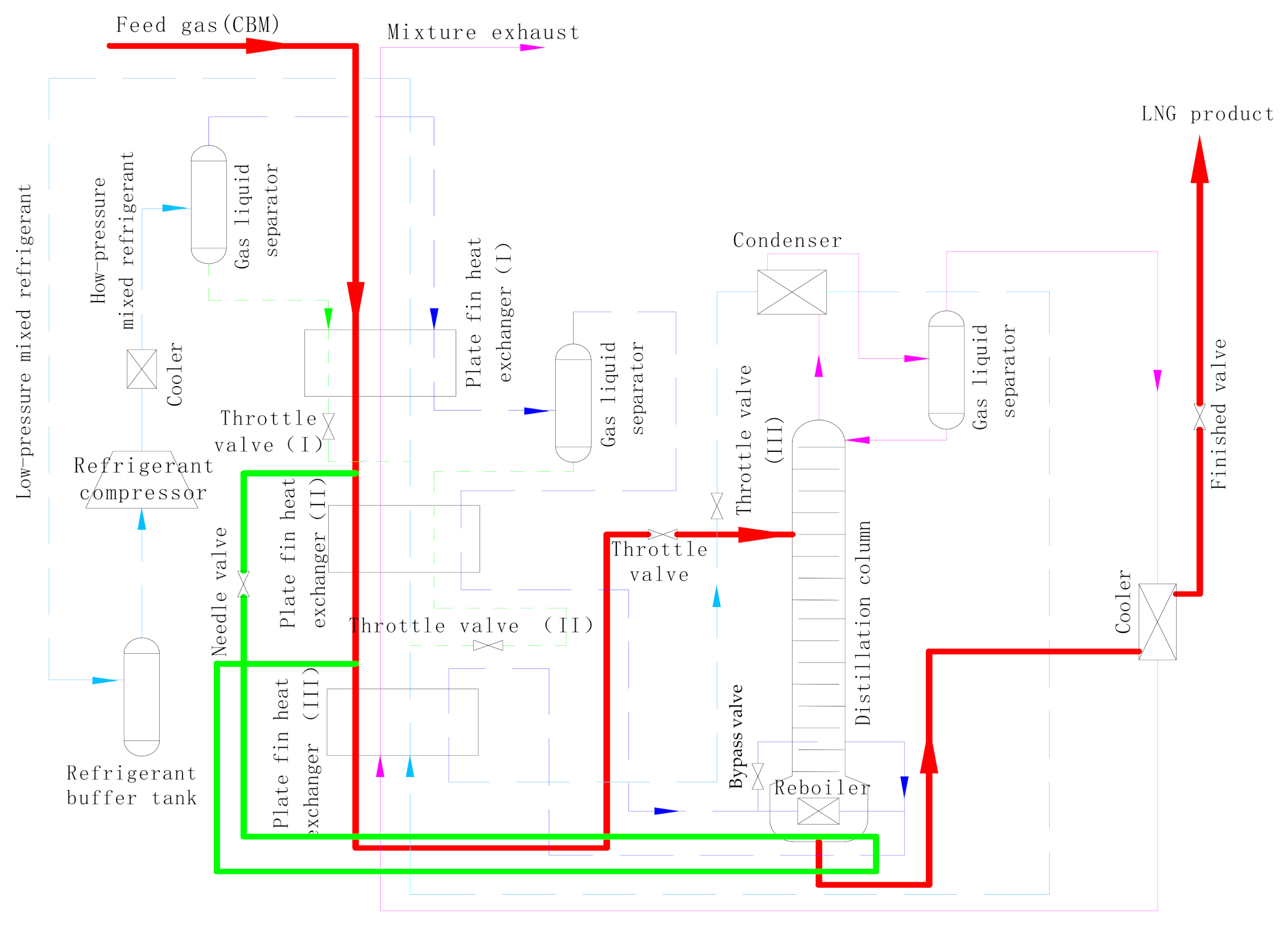
(1) When mixed refrigerant is heating the bottom of distillation column, the feed gas from plate fin heat exchanger I should be separated into a part of the reboiler, and the flow rate should be controlled by needle valve or regulating valve [
15]. The separated feed gas heating column of the bottom reboiler flows back to the feed gas channel in front of plate-fin heat exchanger III, and continues to be cooled after mixing with the original coalbed gas, as shown in
Figure 5. When the purity of the product needs to be adjusted, the flow of the feed gas can be changed. Change of the refrigerant flow should be reduced as much as possible so as to reduce the interference between improving the purity of the product and the recovery of methane.
(2) The stability of operation parameters is very important for the operation of a liquefied cold box in a cryogenic environment. In the process of operation, a new material and energy balance will be established after operation parameters change. If the adjustment is not timely, a large quantity of methane components will escape from the top of the distillation column, which seriously affects methane recovery. In addition, the frequent change to product purity will also increase the evaporation of liquid in the LNG tanks, thus affecting product sales. In the process design, the design temperature at the bottom of the distillation column was increased, and the overall cooling load (especially the cooling load in the low temperature section) was increased, resulting in excessive cooling capacity [
15]. Since excessive cooling capacity reduces product purity, the bypass control valve can be used to control the refrigerant flow through the reboiler, so as to improve the evaporation capacity at the bottom of the distillation column and promote the escape of nitrogen and oxygen components from the liquid at the bottom of the column. Although this method uses a small amount of energy, it can improve the stability of the operating parameters of a plant so as to stabilize the purity of the product entering the LNG storage tank, the production rate, and the methane content of the exhaust gas discharged into the atmosphere. The economics make it worth it.
(3) Due to the large leakage amount of piston compressor, the working pressure and the components of coolant circulation are difficult to maintain stably, so a centrifugal type compressor is recommended for industrial plant design [
22,
23], or else a labyrinth compressor is recommended [
24]. A mixed-refrigerant compressor would increase the amount of initial investment required by a small amount, but the maintenance workload is small and the output and supply of products are stable.
6. Conclusions
(1) In order to ensure highest possible recovery of methane, when the column top temperature rises to −178 °C, it is necessary to adjust the refrigeration cycle and refrigerant components immediately by increasing the cooling capacity of the distillation column, reducing the column top temperature, and making the operation parameters of the cold box return to the normal design value so as to ensure that the recovery of methane is stable above 90%.
(2) To ensure the safe storage of the LNG products, the oxygen content of the LNG products should not exceed the standards during the actual operation. Therefore, the bottom temperature of the distillation column should be controlled at −143 °C.
(3) In order to increase LNG product output and ensure their purity at the same time, the following two measures should be adopted in industrial plant scale-up design for the cryogenic liquefaction of low concentration coalbed methane: (i) when heating the bottom of the column with the refrigerant, the feed gas from the middle of plate fin heat exchanger should separated into a part of heating reboiler at the same time, with the flow controlled by needle- or regulating valve; (ii) the design temperature of the bottom of the column and the overall cooling load (especially in the low temperature section) should be increased, and the bypass valve (regulating valve) can be used to control refrigerant flow through the reboiler so as to adjust the evaporation in the distillation column.
(4) In order to avoid a decrease of refrigeration cycle operating pressure due to refrigerant leakage, a centrifugal or labyrinth compressor should be selected as mixed refrigerant compressor in the design of industrial plant, so as to maintain stable product output and supply.


