Article

Investigation of the Process of Simple Distillation in Irrigated Pipe Elements

by
Artem Sergeevich Ponikarov
*,
Sergey Ivanovich Ponikarov
and
Eduard Vladislavovich Osipov
Department Mechanical Engineering for Chemical Industry, Faculty of Mechanical Engineering, Kazan National Research Technological University, 420015 Kazan, Russia
*
Author to whom correspondence should be addressed.
Processes 2021, 9(11), 2047; https://doi.org/10.3390/pr9112047
Submission received: 28 September 2021 / Revised: 9 November 2021 / Accepted: 11 November 2021 / Published: 16 November 2021
(This article belongs to the Topic Modern Technologies and Manufacturing Systems)

Abstract

:
In modern chemical and oil refining complexes, separation processes are among the most popular and energy-intensive. Installations for their implementation should be equipped with nodes for creating vapor (evaporators) and liquid (deflegmators) irrigation. Evaporators of any type (film, thermosiphon, gas lift, cubic) belong to this class of devices. For example, in cubic evaporators, the gas flow is completely formed from flux bubbles that originate on the heat-conducting surface and float in the volume of the cubic liquid located in the apparatus. Due to the accompanying mass exchange, the bubbles are enriched with volatile components during ascent and noticeably increase in volume, and the growth of the bubble is determined, among other things, by the total flow. At the same time, in real bubbling-type equipment, the total mass transfer surface exceeds the cross-section of the device itself by more than two orders of magnitude. Thus, according to, the ratio of the internal cross-sectional area of the apparatus to the developed mass transfer surface is 0.0015–0.002. Based on the analysis of the integral equation of the diffusion boundary layer, it is shown that the presence of a resultant flow of substance through the phase interface (non-equimolarity of the process) in a two-phase gas (vapor)–liquid system leads to the transformation of the structure of the traditional mass transfer equation itself. The use of a new structure obtained for both binary and multicomponent mixtures makes it possible to significantly simplify the approach to the description and generalization of arbitrary mass transfer processes. The innovativeness of the proposed approach lies in its universality for non-equimolar processes. This simplifies the creation of models of any mass transfer devices and entire production lines. In addition, the proposed approach is a good auxiliary tool for various researchers and experimenters. It should also be noted that the separation processes of many products of organic origin during heating are characterized by the appearance of undesirable side reactions (thermal decomposition, condensation, polycondensation, formation of harmful impurities, etc.), which occur most intensively in the heating zones. At the same time, the evaporation and distillation units are subject to requirements for the minimum hydraulic resistance of the structure, the maximum separation capacity (efficiency), and the minimum residence time of the product in the apparatus (equivalent to the minimum holding capacity of the structure). It was noted that the specified requirements are most fully met by film-type devices.

1. Introduction

In view of the obvious influence of the velocity of the total phase flow flowing around the interface on the diffusive mass transfer between the core of the flow and the interface, the description of non-equimolar mass transfer becomes more complicated, starting from the very structure of the mass transfer equation [1,2,3,4]. This circumstance is explained by the transformation of velocity profiles and concentrations of the main flow under the influence of the transverse velocity component, which can occur under the influence of the diffusion stream, and under the influence of the transverse velocity component on the hydrodynamic characteristics of the boundary layer. As a result, in turbulent streams, mass transfer is characterized not only by molecular diffusion, but also by turbulent diffusion, which in turn depends on the density of the transverse mass flow. Thus, bubbling columns and rectors were considered in [5], and the influence of the hydrodynamics of the process on the mass transfer coefficient, which is a key parameter for evaluating the operation of a gas–liquid contact device, was analyzed. P. Ham used a phenomenological relation that allows calculation in a more rigorous formulation of the problem.
To date, the kinetics of non-equimolar mass transfer is described by several basic methods:
  • A method for determining the mass transfer coefficients in the vapor and liquid phases, during rectification based on the data of a physical experiment on the profiles of component concentrations along the height of the column, for the equimolar formulation of the problem [6,7,8].
  • The method of coupled physical and mathematical modeling based on the variational formulation of conservation laws [9].
  • The method of “prototyping” mass transfer processes [10,11,12].
The first direction under consideration is based on the determination of mass transfer coefficients in the vapor and liquid phases from experimental data on mass transfer in two-phase systems and the determination of component concentration profiles by column height. The authors [2,3,4] note the need for a more rigorous formulation of the problem, especially when calculating the mass transfer coefficients in the vapor and liquid phases from experimental data. At the same time, difficulties arise when extracting mass transfer coefficients from a physical experiment in a distillation column [6,7,8].
The second direction—“the method of coupled physical and mathematical modeling based on the variational formulation of conservation laws” is based on the relationship of hydrodynamic and mass transfer characteristics of the process. The method consists in representing the processes occurring in the equipment in the form of elementary zones with a certain structure formed by the design of the apparatus and depending on the space-time frame. The mathematical description of each zone is carefully verified during the physical experiment on laboratory models. “The invariance of the structure of the description of the elementary zone to the scale of the apparatus as a whole is postulated” [9]. The third direction is based on an algorithm for generating a vapor potential based on the chemical characteristics of molecules to close the design of devices. For this purpose, the most important parameters of the system under consideration were identified: parameters such as the depth of the potential well and the effective diameter of the potential molecule, as the most approved in thermophysical practice, are determined [10,11]. The interaction within molecules is determined by quantum mechanical parameters: the length and the binding energy [12].
In the work of L. A. Serafimov [13], using the theory of thermodynamics of irreversible processes, it is shown that even for an equimolar process in a strict formulation of the problem, the structure of the equations of multicomponent mass transfer differs very significantly from the phenomenological relations. The calculation was based on multiple regression of logarithmic dimensionless variables and was coupled with experimental data; the deviation was less than 10%.
In the article [14], the authors conducted a numerical analysis of evaporation from the surface of a liquid film of binary composition (a mixture of water and ethylene glycol). The results of the analysis reflect the influence of the input parameters of the gas and liquid film on the temperature and concentration profiles. Thus, it was found that the concentration of ethylene glycol in the liquid phase has a great influence on heat and mass transfer. Moreover, when its concentration in the mixture is less than 40%, more water evaporates than if the film consisted only of pure water under the same conditions.
In [15], A. Stankevich and Ya. Mulein considered the existing methods used to intensify the processes of mass transfer. The authors considered new designs of mass transfer equipment for the chemical and petrochemical industries. New engineering solutions were also offered for the construction of contact devices for absorbers and rectification columns. The proposals considered “promise impressive improvements in the productivity and efficiency of equipment, as well as noticeably decreasing their linear dimensions” [15].
In [16], mass transfer is described by criterion equations using Nusselt and Sherwood numbers. The authors investigated the features of mass transfer during condensation of vapor–gas mixtures. The experiments were carried out in circular channels filled with moist air. There was a temperature gradient on the channel walls, thereby causing changes in saturation conditions, in addition to condensation or evaporation from the walls. Moreover, the paper clearly demonstrates how the film layer of condensate changes over time, increasing during condensation and thinning during evaporation.
The article [17] provides a solution to the problem of heat and mass transfer under conditions of phase transformations or chemical reaction, which gives an approximate method for solving a system of kinetic equations. Using the example of calcining limestone particles, it is shown that continuous solutions can be obtained for all stages of the process [17]. The proposed method is applicable to solving specific problems of heat and mass transfer under conditions of chemical reactions or structural transformations, which can be useful for theoretical analysis of the kinetics of technological processes.
When calculating mass transfer coefficients, researchers quite often use criterion numbers, and, consequently, similarity theory, which in general, as mentioned above, certainly affects the accuracy of the problem statement during its study. For example, in [18,19], mass transfer was studied during the reaction of a coke solution (Ccoke + CO2 = 2CO), which is essentially a special case of a non-equimolar process. However, non-equimolar diffusion in the process of external and internal diffusion was often neglected when studying the reaction of loss of coke solution. Junchen Huang mentions that the solution losses were 25% by mass, which indicates the tangible contribution of non-equimolarity in modeling mass transfer.
A similar approach is used in the work [20], in which a new process for the production of ultrapure gasoline was presented, which solves the problem of loss by loss of octane number (ON) during desulfurization. In the production of pure gasoline, using naphtha obtained by catalytic cracking (FCC), this problem is well known. The authors propose an approach to using a unique approach to separation: regression calculation of LLE results [19].
The analysis of works devoted to non-equimolar transfer of matter shows that relatively reliable calculation methods have been developed only for cases of evaporation and condensation of pure components in an inert medium. It should be noted that in these works, studies were carried out either of the processes of heat and mass exchange or evaporation of a liquid at a temperature below its boiling point, and the influence of the Stefan flow on mass transfer was also studied.
The scheme of interaction of phase flows in a single tube element of the film apparatus is shown in Figure 1. Mass transfer between the phases occurs on the contact surface of the phases between the liquid film flowing down the inner wall of the pipe and the steam flow rising up the pipe. This scheme corresponds to the countercurrent mode of phase interaction. For the direct flow scheme, the picture does not change fundamentally. It should also be taken into account that, for a significant class of devices (film evaporators, distillers), the entire vapor irrigation flow is formed due to partial evaporation of the liquid film, and vice versa—for partial condensers—the entire liquid irrigation flow is formed due to partial condensation of the flux flow. Evaporation or condensation is achieved at the same time due to the external supply (removal) of heat through the pipe wall. At the interface itself, in each section, it is assumed that a thermodynamic equilibrium is achieved between the interacting phase flows [Px = Py; Tx = Ty; yf = y ∗ (xf)].

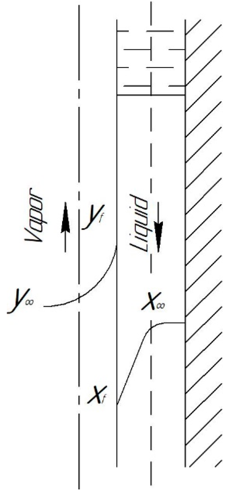
2. Mass Transfer in the Film

In this case, in the film column, the intensity of one of the flows will increase from the initial (zero) value to the final (maximum) value, and the intensity of the other flow will progressively decrease. The effect of the convective (total) mass flow on the mass transfer is maximized in this case. Therefore, when calculating the mass transfer process, it becomes necessary to specify the distribution of the total flow along the interface of the phases. In relation to evaporators, condensers, and distillers, this condition must be met on the basis of appropriate thermal calculations. Another formulation of the problem can also be used: an initial task of the distribution of the total flow along the interface, followed by a thermal calculation to determine the appropriate profile of the heat supply (heat sink) along the interface to ensure a given technological condition.
As already noted above, the interface itself is characterized by a complex wave structure, the state of which is determined by the flow regime of the liquid film. However, in most studies, this circumstance is not taken into account, and the surface itself is taken as a smooth cylindrical film: F = π ( d 2 δ ¯ ) H . When calculating this surface, the average thickness of the film is used. According to [2], the error in determining the interface area resulting from this assumption can reach 15%. At the same time, because in the known generalizations the mass transfer coefficients were also calculated taking into account the same assumption, errors in determining the contact area of the phases are, to a certain extent, compensated by a corresponding increase in the calculated mass transfer coefficients included in the generalizing equations. Obviously, the mass transfer coefficients in this case should be considered as some conditional coefficients related to some conditional surface, which is rigidly related to the height of any arbitrary section of the pipe.
Most researchers [2] write the mass transfer processes as:
N f = G d y = β y ( y f y ) d F
Or:
N f = L d x = β x ( x x f ) d F
As is evident here, the mass transfer equations are special cases of the equations for the transition from a multicomponent mixture to a binary one and for neglecting the total flow, i.e., for an equimolar process [21,22,23]:
N f = [ B f , y ] ( y f y ¯ ) p N c ( y f y ¯ ) + N c y f
N f = [ B f , x ] ( x ¯ x f ) p N c ( x ¯ x f ) + N c x f
( y ) = ( k ) · ( x )
When taking a linear dependence for the equilibrium line ( y f = m x f + b ), a transition to the mass transfer equations can be implemented:
N f = G d y = K o y ( y y ) d F
or   N f = L d x = K o x ( x x ) d F
where   1 / K o y = 1 / β y + m / β x
and   1 / K o x = 1 / β x + 1 / m β y
In Equation (6), the transfer coefficients and driving forces are expressed in terms of the corresponding characteristics of the vapor phase, and, in Equation (7), in terms of the characteristics of the liquid phase. The phase resistances to the mass transfer process are determined by the values of the mass transfer coefficients, so Equations (8) and (9) are called the phase resistance additivity equations.
When conducting experiments on the study of mass transfer in devices of any type, the researcher can obtain information only on the mass transfer coefficients. The transition to information about the mass transfer coefficients can then be obtained only on the basis of model representations, for example, from the analysis of Equations (8) and (9). To date, a large number of methods have been developed for decomposing the total mass transfer coefficients into partial mass transfer coefficients [2,24].
Generalization of the experimentally obtained information about the mass transfer coefficients in the vast majority of cases was carried out by researchers using the apparatus of similarity theory. Generalizations were carried out for narrow groups of processes: rectification, absorption, evaporation, etc. In turn, the calculation procedure assumes the use of mass transfer coefficients of only one type—equimolar. In the future, only generalizations for the rectification process will be mainly used. When calculating the processes occurring in multicomponent mixtures, binary mass transfer coefficients are also used for all binary pairs that make up the multicomponent mixture. It is assumed that the binary mixtures are located in a hydrodynamic environment (Re = idem, μ = idem, σ = idem, etc.), corresponding to the conditions of separation of the multicomponent mixture, but differing from each other in their diffusion characteristics.
Certain difficulties arise in this case, especially for devices operating in conditions of pronounced non-equimolarity. Thus, in film evaporators of the countercurrent type, the flow modes of each of the phases, as already noted, vary very widely. Moreover, in some cases, the physically realizable conditions for the existence of film flows may be violated. In these cases, it is necessary to use pipes of variable cross-section according to the height of the device in order to avoid the occurrence of choking or tearing of the film. Accordingly, the calculation procedure should provide for checking the flow modes of the phases and the selection of criteria equations corresponding to specific conditions of phase interaction.
S h = Ψ ( R e , S c , R e n . e . )
R e y = E k d ρ y V y
R e x = E k δ ρ x V x
In Equations (11) and (12), Ek is the total flow expressed in mass units (kg/(m2⋅s)), and these expressions themselves are analogs of the Reynolds criterion for the transverse flow of a substance in the pipe. The authors note that the expression (10) is valid only for local pipe sections with specific values of the variables included in it. In [2], an attempt is made to obtain the flow using these criteria and mass transfer equations, which are already characterized by significant complexity for binary mixtures. Therefore, the practical use of this approach is problematic. The authors draw an interesting conclusion that “partial condensation in a wide range of thermal loads has the opposite effect on the kinetics of mass transfer in the vapor and liquid phases.” It can be noted that this conclusion directly follows from the structure of the Equations of non-equimolar mass transfer for the vapor and liquid phases (3)–(5) proposed in this paper. Moreover, in this case, the effect of continuous redistribution of phase resistances in the process of non-equimolar mass transfer is easily explained and taken into account for any processes for both binary and multicomponent mixtures.
Most reliable generalizations in the field of the kinetics of mass transfer processes for both vapor and liquid phases have been made for turbulent flow regimes [2,3,4,21,22,23,24,25,26,27]. This is natural, because it is in these areas that real mass transfer devices are operated. At the same time, within the framework of the proposed approach, the field of actual operating modes of the equipment has significantly expanded and covers low-intensity flow modes of one of the phases, up to laminar modes. However, the presence of a convective flow of matter through the interface greatly affects the diffusion transfer. Moreover, under conditions of significant non-equimolarity in low-intensity flow regimes, the diffusion process in the corresponding phase can be completely blocked, and the mass transfer can be completely controlled by the diffusion resistance of another interacting phase, which in this case must be in a turbulent flow mode. These circumstances reduce the loss of calculation accuracy caused by possible errors in the calculation of mass transfer coefficients. Thus, when calculating the mass transfer processes, the following criteria equations were used to calculate the mass transfer coefficients.

2.1. For the Gas (Vapor) Phase

  • Laminar flow mode (Re ≤ 2300):
    S h y = 0.5 R e y S c y ( L d 2 δ e q )
    which was obtained theoretically and confirmed experimentally [27].
  • Turbulent mode (Re > 2300) equation:
    S h = 0.0345 R e 0.75 S c 1 + 0.75 R e 0.08 { S c 1 + ln [ ( 1 + 5 S c ) / 6 ] }
    which was obtained in [26] on the basis of a numerical experiment on a mathematical model, and correlates well with the data of a number of researchers [21,22,23].

2.2. For the Liquid Phase

  • Laminar wave-free mode ( R e G < 12 ). In this mode, the stability of the film flow and the very possibility of its existence is easily violated. Therefore, in this mode, the mass flow of any component was calculated without taking into account the diffusion flow (only by the convective component of the total flow).
  • Laminar wave modes ( 12 < R e G < 320 )—V. A. Malyusov’s equation was used [28]:
    S h x = 0.0018 R e x 0.667 S c x 0.5
  • The turbulent mode ( R e G < 320 ) is represented by the equation:
    S h x = 0.0035 R e x 0.5 S c x 0.5
    which was obtained by the generalization of experimental data on rectification in a film column [29].

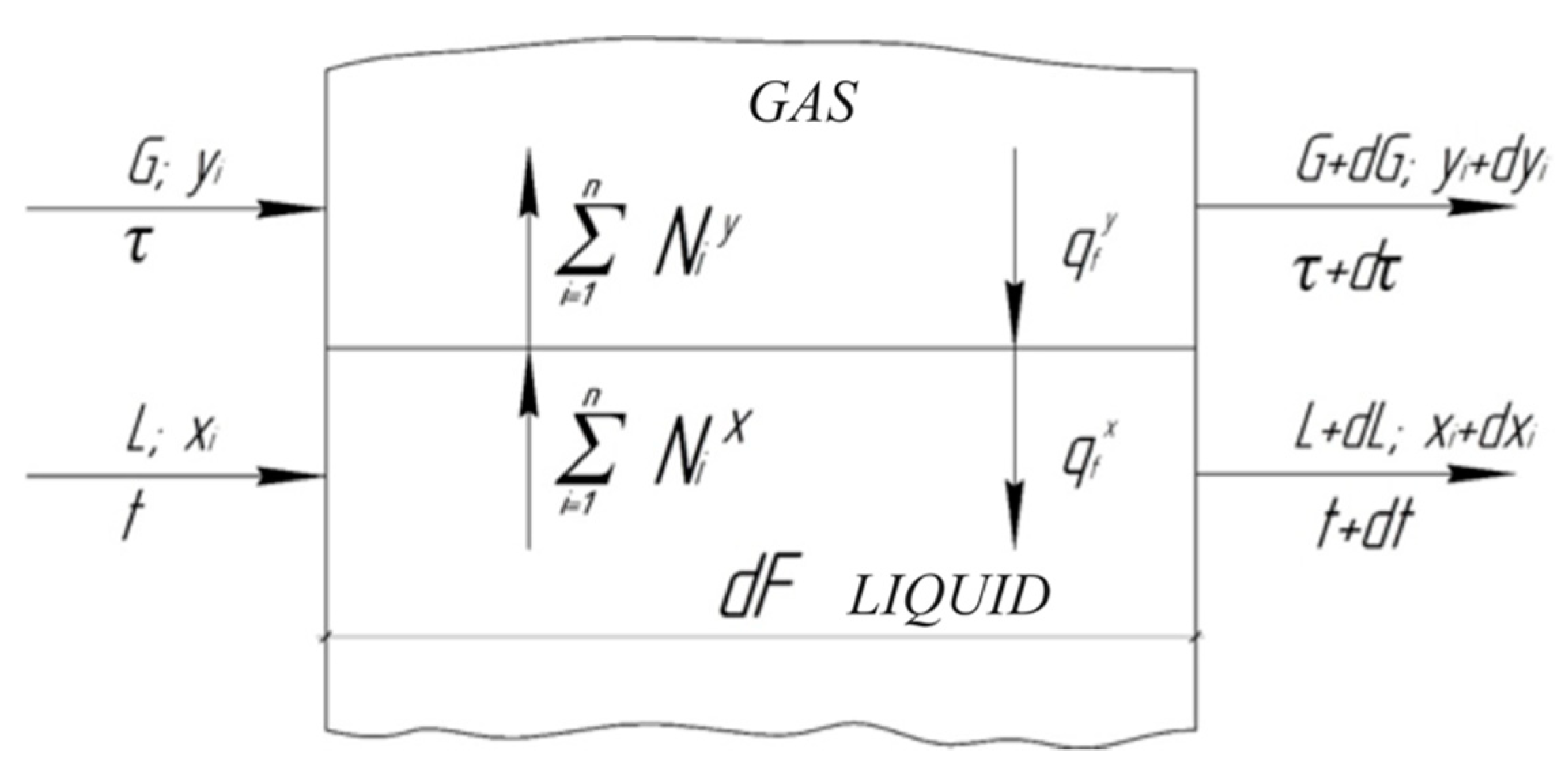
3. Mass Transfer in Irrigated Pipe Elements

3.1. Development of an Algorithm for Calculating Mass Transfer in Irrigated Pipe Elements

Based on the developed mathematical description of the processes of non-equimolar mass transfer, a method was developed for calculating the mass transfer process in a film apparatus by integrating the mass transfer equations over the interface. For an infinitesimal surface element, the scheme can be shown as in Figure 2:
N i , f y = d ( G y ¯ i ) d S
N i , f x = d ( L x ¯ i ) d S
N c y = d G d S
N c x = d L d S
y i , f = K i , f x i , f
1 n y i , f = 1
d ( G y ¯ i ) d S = [ B i , j , y ] ( y i , f y ¯ ) p d G d S ( y i , f y ¯ ) + d G d S y i , f
d ( L x ¯ i ) d S = [ B i , j , x ] ( x ¯ i x i , f ) + p d L d S ( x ¯ i x i , f ) + d L d S x i , f
d ( G y ¯ i ) = d ( L x ¯ i )
K i , f = f ( P , t f , x i , f )
The system of Equations (17) and (18) allows us to calculate the characteristics of the output flows for the known values of the characteristics of the input phase flows ( G n ,   y i , n , L n ,   x i , n ) , the availability of information about the transfer coefficients ( B i , j , y ,   B i , j , x ) , and the regularities of the formation of vapor–liquid equilibrium. For numerical integration, the apparatus (pipe) is divided into a number of sections with a length within which all the kinetic coefficients, and hence the mass flows, can be assumed constant. Trial calculations have shown that the length of a separate section can be taken in the range of 100–200 mm. Further reduction in the length does not lead to an increase in the accuracy of the result.
Because the total flow occurs in the apparatus as a result of heat supply (heat removal) through the pipe wall, it is necessary to supplement the system (17) and (18) with heat balance equations or use any additional conditions to determine the temperature of divergent flows. It is most convenient to use the assumption that the contacting phases, the composition of which is determined by the average discharge concentrations for the corresponding cross-section, are under saturation conditions, i.e., their temperature corresponds to the dew point.
The algorithm is designed to solve the problem in a verification statement: the flow rate and composition of the power flow and the geometry of the device (diameter, length, and number of contact tubes) are set as initial data. The separation calculation is carried out for a single tube, i.e., the assumption is made about the uniformity of the distribution of power across all tubes. The calculation is carried out in the following sequence:
Based on technological considerations, the distribution of the total flow along the mass transfer surface is set (for example, uniform).
For all sections of the pipe, an initial approximation is built for the costs and compositions of liquid irrigation. When forming an initial approximation of the flow rate, the characteristics of the power flow are used.
Further calculation of the separation process is carried out from the bottom up (from the lower section of the pipe to the upper one).
For each calculated section of the pipe, according to the equations, the thickness of the liquid film is calculated, the conditions for ensuring the integrity of the liquid film are checked, and its flow mode (ReL) is calculated. For the gas phase, the condition for the presence of a reserve in terms of the choking rate is checked and the mode of its flow (ReG) is calculated. All the necessary physical and chemical properties (temperature, density, viscosity, diffusion coefficients, etc.) are calculated for the average section of the site. The criterion equations are selected and the mass transfer coefficients are calculated for both phases of the system ( β i , j , y ,   β i , j , x ) .
The joint solution of the mass transfer Equations (23) and (24) provides the mass flows of components formed in the calculated section ( N i , f ) . The calculation is reduced to finding the concentrations of phases on the interface that ensure the fulfillment of conditions (25) and (26). When searching for the roots of a solution, for example, the Newton method can be used.
According to the known values of mass flows, the characteristics of the output phase flows are calculated:
G j = G j 1 + N c d S
L j = L j + 1 N c d S
y j , i = G j 1 y j 1 + N i d S G j
x j , i = L j + 1 x j + 1 , i N i d S L j
The previously accepted values of expenses and flow compositions are replaced by the newly calculated ones.
Based on the assumption that the average discharge compositions of the interacting phases correspond to the saturation conditions, the temperatures of divergent flows are calculated. The newly calculated characteristics of the phase flows are placed in all the calculated cells instead of the previously accepted ones.
After completing the calculation procedure for all sections of the tube (cells), the condition for achieving a stationary state of the system is checked, which is characterized by the fulfillment of the condition:
Δ i = F x f , i D y D , i W x W , i ζ i
where ζ i = 10 4 is the specified accuracy of the solution. In this case, yD,i and xW,I are defined, respectively, as the composition of the vapor leaving the last (upper) cell and the composition of the liquid leaving the first (lower) cell.
If condition (31) is not met, the calculation is performed again. When the condition is met, the calculation is completed.
The method used to find a solution for a multi-element apparatus is a kind of method of simple iterations and has received the name “relaxation method” in the literature [24]. It is proved that its application provides reliable and fairly fast convergence. It is also very economical from the point of view of programming and in machine implementation. In this paper, the calculation program for the distillation apparatus was developed using the ANSYS Fluent software and computing complex. Because this is compatible with the universal modeling program HoneyWell UNISIM, all information on physical and chemical properties and vapor–liquid equilibrium was extracted directly from it.

3.2. Experimental Study of the Simple Distillation Process

To verify the developed method of kinetic calculation of film mass transfer devices, data from an experimental study of the simple distillation process performed at the Tallinn Polytechnic Institute by Yu. I. Kallas was processed [3,4].
The experiment was carried out in a single-tube film column with a heated outer wall; the scheme of the experimental installation is shown in Figure 3.
In the experiment, the liquid heated to the boiling point flowed down the inner surface of the distillation pipe (din = 0.016 m, L = 0.85 m, L/din = 53) and evaporated due to the heat flow supplied to the wall.
The heating conditions of the wall provided a relative constancy of the transverse mass flow along the height of the apparatus. In experiments in the steady-state mode, for a certain period of time, the distillate vapors leaving the top of the column were selected, the relative selection of the distillate was measured, and its composition was analyzed. The study was conducted on four mixtures (benzene-toluene, n. hexane-n. heptane, ethanol-water, and n. hexane-benzene), which significantly differed in their physico-chemical properties. Several series of experiments were carried out on each mixture with different compositions of the initial mixture. Within each series of experiments (25–35 points), the relative selection of distillate (D/F) and the duration of the experiment changed, which made it possible to change the evaporation intensity of the mixture (Nc) and the modes of movement of both the vapor and liquid phases (Rey, Rex) within a wide range. The total number of conducted experiments exceeded 220.
Yu. I. Kallas also carried out a joint solution of the equations of convective diffusion and continuity using the following assumptions [3,4]:
  • The laminar flow regime of the gas phase ( ε D = 0 ) is considered;
  • The transverse mass flow ( N c ) is constant over the entire height of the pipe;
  • The equilibrium dependence is linear ( y = m x + b ) ;
  • A linear profile of concentrations along the pipe height is adopted.
The accepted assumptions allowed the author to obtain an expression that determines the concentration profile in an arbitrary pipe section:
d y d r = 2 ( y ¯ H y ¯ K ) z r H e x p ( N c     r 2 4     H     D ) e x p ( N c r 2 4 H D ) 1
Equation (32) allows us to find the value of the concentration gradient on the interface of the phases (r = R), and hence the value of the mass flow of the component through the interface of the phases:
N = D · d y d r | r = R + N c · y f
The assumptions made by Yu. I. Kallas very much coarsen the decision. In particular, this applies to the neglect of the turbulent diffusion coefficient. Similarly, there is little justification for the assumption of the linearity of the concentration profile along the pipe height, especially for long pipes that are used in real evaporators and distillers.
In addition, as was proved in [21,22,23], the total flow also transforms the diffusion component of the mass flow through the phase interface, both for laminar and turbulent modes, which is not taken into account in the work of Yu. I. Kallas. Nevertheless, with the help of the assumptions made, the author was able to obtain an expression for calculating the boundary concentration (yf), to relate the kinetic regularities of the concentration of the oncoming vapor and liquid flows in the film column, and using balance ratios to obtain an expression for calculating the composition of the distillate leaving the pipe:
y ¯ D , i = A I ( 1 I 1 ) · m ( 1 I 1 ) · b · C 1 + B I + ( 1 I 1 ) · b · E
where A, B, C, E, I are expressions that take into account the balance relations, the diffusion properties of the vapor and liquid phases of the separated system, and the geometric dimensions (d, L) of the apparatus; m and b are the coefficients of the equilibrium dependence equation. Experimental verification of Equation (34) confirmed its acceptable accuracy [25].
It is of interest to analyze the last assumption used by Yu. I. Kallas [3,4,25], because it allowed the author to obtain an analytical solution to the problem. For a film machine:
d S = 2 · π · R d z
y ¯ i | z = z = 0 z N i d z 0 z N c d z = 1 N c 0 z N i d z z ,
d y ¯ i d z = 1 z · [ ( N i N c ) z = z ( y ¯ i ) z = 0 ]
( y ¯ i ) z = 0 = ( N i N c ) z = 0
It is evident here that the concentration gradient in the film apparatus depends both on the current value of the mass flow in the section under consideration and on the longitudinal coordinate. Therefore, the assumption that the concentration gradient is constant over the pipe height is not obvious. It is known that for monotone functions, the second derivative of which preserves the sign on the considered section (0 < z < H), the best linear approximation for the derivative is its value determined in the middle of the section (z = H/2). Then, by solving the system of Equations (35)–(38), we obtain:
y ¯ D , i = 0.5 · [ ( N i N c ) z = 0 + ( N i N c ) z = H ] ,
Equation (39) should be considered as an approximate solution of the film distillation problem in the binary formulation of the problem. The calculation of the flows is carried out according to the mass transfer equations for only two sections of the pipe (z = 0 and z = H). When using the condition on the linearity of the equilibrium dependence, analytical dependences similar to (35) can also be obtained from (39). In the multicomponent formulation, Equation (35), of course, is also not applicable. The use of (39) in this case, although it is possible in principle, is not justified enough. In a more rigorous formulation, the calculation should be carried out directly by numerical integration of the complete system of Equations (23)–(26) according to the algorithm described above. To implement a specific calculation procedure for a simple distillation process, this algorithm can be reduced to the form shown in Figure 4, in which the condition of constancy of Nc in the height of the pipe is established. The algorithm can also be easily transformed for other conditions.
To compare the adequacy of the considered models, experimental data were processed [3,4]:
  • The composition of the distillate was determined by the analytical expression (35) proposed in the work of Yu. I. Kallas [24]—model No. 1;
  • The distillate composition was determined by numerical integration of the system of Equations (17)–(26) according to a specially developed iterative algorithm (Figure 4)—model No. 2;
  • The distillate composition was determined by the analytical expression (39)—model No. 3.
For comparability of the results, all the physico-chemical properties of the mixtures were calculated using the formulas used in [3,4,30]. The equilibrium state of the systems at the interface was described using the database of the HoneyWell UNISIM program (license 17d3-8598-20a7-b2ec-WEB) [30,31]. A comparison of the calculated values of distillate concentrations with experimental data is presented in Table 1. As a criterion for the adequacy of each of the models, the value of the standard deviation of the calculated values of distillate concentrations from the experimental data for each of the series of experiments was taken:
Δ = i = 1 i = n ( Δ c a l c Δ e x p e r ) 2 n ,
where n is the number of experimental points in each series of experiments, Δcalc—calculated values of distillate concentrations, Δexper—experimental values of distillate concentrations.

4. Results and Discussion

It is clear that, in all cases, when using model No. 2, the standard deviation was found be significantly smaller (by 2–3 times) than when using special models developed only for the simple distillation process and only in the binary formulation of the problem. This fact confirms a certain universality of the proposed mathematical description and the expediency of its use for describing arbitrary non-equimolar mass transfer processes.
The effects of non-equimolarity are determined both by the direction of convective mass flows (Nc) and by the relations between Nc and the coefficients of equimolar mass transfer, which would be formed in the considered apparatus in a similar hydrodynamic situation (Re = idem, Sc = idem). This relation for binary systems was previously called by us the non-equimolarity factor of the process, which can be considered as a similarity criterion that does not depend on either the type of the modeled process or its hardware design.
In the process of simple distillation, the effect of redistribution of phase resistances to the mass transfer process is very clearly visible, depending on the degree of non-equimolarity of the process. Indeed, under non-equimolar conditions, the diffusion flow is only a part of the total mass flow. In accordance with the structure of the mass transfer Equations (23) and (24), with a positive direction Nc (distillation process), the relative fraction of the resistance of the liquid phase increases, which is manifested in an increase in the ratio of the concentration difference ( x ¯ x f ) / ( y f y ¯ ) in the diffusion boundary layers of the contacting phases in comparison with the equimolar process. Our calculations showed that the proportion of the resistance of the liquid phase in the total resistance to mass transfer for the mixtures under consideration was 92–100%. Interestingly, the same effect was noted by Kallas Yu. I. [24]. At the same time, for equimolar conditions for the same mixtures, more than 80% of the mass transfer resistance is controlled by the resistance of the gas phase. It is obvious that neglecting the effects of non-equimolarity in this case can lead to significant errors in the calculations of mass transfer processes. For processes with the opposite direction of Nc (condensation, desorption processes), the effects will obviously be reversed.

5. Conclusions

Thus, based on the generalization and analysis of the relatively extensive experimental material accumulated in previous studies, the adequacy of the proposed structure of the mass transfer equations can be considered proven, in addition to the independence of this structure from the conditions of flow around the interface of the phases, i.e., from the hardware design of the process.
The adequacy of the proposed structure of the mass transfer equations and its independence from the flow conditions of the interface were confirmed by generalization of the experimental material and a numerical experiment on a mathematical model. The program for calculating the mass transfer process in film apparatuses, which is suitable for calculating arbitrary mass transfer processes (absorption, rectification, desorption, evaporation, etc.) performed in a multicomponent formulation, is used in the practice of design work.

5.1. Conventional Designations

  • H—the height of the device, or the pipe section, m;
  • B*—elements of the square matrix of coefficients of multicomponent equimolar mass transfer, m3/(m2 s); kg-mol/(m2 s);
  • D—binary diffusion coefficients, m2/s;
  • d—the diameter of the device, or the pipe section, m;
  • F, G, L—power consumption, steam, liquid phases, respectively, m3/s; kg-mol/s;
  • g—acceleration due to gravity, m/s2;
  • idem—the property of an object or operation, when reapplying the operation to the object, give the same result as when the first
  • k—the number of components in a multicomponent mixture;
  • K—mass transfer coefficient, m3/(m2 s), kg-mol/(m2 s);
  • L—length of the device (pipe), m;
  • m and b—coefficients of the linearized equilibrium curve;
  • N —substance stream, m3/(m2 s), kg-mol/(m2 s);
  • P—pressure, Pa;
  • p—concentration parameter [24];
  • q—substance stream, m3/(m2 s), kg-mol/(m2 s);
  • R—pipe radius, m;
  • S—phase separation surface, m2;
  • t—temperature, K;
  • τ, ˦—time, s;
  • Ψ—pseudo-concentrations of the linearized equation of multicomponent mass transfer, respectively;
  • y and x—molar concentrations of gas and liquid, mol. fraction;
  • y ¯   and   x ¯ —average volume molar concentrations of gas and liquid, mol. fraction;
  • r and z—the transverse and longitudinal coordinates, respectively;
  • δ—the thickness of the liquid film, m;
  • ε D —coefficient of turbulent diffusion, m2/s;
  • Δ a v —the standard deviation between the calculated and experimental values;
  • [] and 〈 〉—square and column (vector—column) matrices, respectively;
  • R e = ω ι / υ —the Reynolds criterion;
  • S h = β 1 / D —the Sherwood criterion;
  • S c = υ / D —the Schmidt criterion.

5.2. Indexes

D and K—the diffusive and convective components of the mass flow, respectively; eq—equimolar; F, D and W—characterize the feed, distillate, and residue, respectively; i, j—components; n—initial; f—the interface of the phases; y—gas phase; x—liquid phase; c—total flow; z, r—directions of the coordinate axes; *—equimolar conditions; -—average output concentrations, coefficients (criteria) calculated using average output concentrations, 0 is the initial value, ∝—phase (core) center.

Author Contributions

Conceptualization, S.I.P. and A.S.P.; methodology, S.I.P. and A.S.P.; validation, A.S.P., E.V.O. and S.I.P.; formal analysis, A.S.P., E.V.O. and S.I.P.; writing—original draft preparation, A.S.P.; writing—review and editing, S.I.P.; visualization, E.V.O.; supervision, S.I.P.; funding acquisition, A.S.P. and S.I.P. All authors have read and agreed to the published version of the manuscript.

Funding

This research was funded by the Ministry of Science and Higher Education of the Russian Federation grant number 075-00315-20-01 «Energy saving processes of liquid mixtures separation for the recovery of industrial solvents».

Institutional Review Board Statement

Not applicable.

Informed Consent Statement

Not applicable.

Data Availability Statement

The data presented in this study are available in several works that have been sighted and listed in the list of references.

Acknowledgments

The team of authors express their gratitude to Telyakov E. Sh., KNITU, for consultations on the theory of mass transfer.

Conflicts of Interest

The authors declare no conflict of interest. The funders had no role in the design of the study; in the collection, analyses, or interpretation of data; in the writing of the manuscript, or in the decision to publish the results.

References

  1. Stage, H.; Schultze, G.R. The fundamental work on theory, apparatus, as well as procedure of distillation and rectification. Chem. Ztg 1970, 94, 271–286. [Google Scholar]
  2. Olevsky, V.M. Film heat and mass transfer equipment. Chemistry 1988, 195. [Google Scholar]
  3. Kallas, Y.I. Investigation of the Process of Continuous Distillation in a Film-Type Apparatus; Candidate of Technical Science Tallinn Polytechnic Institute: Tallin, Estonia, 1972. [Google Scholar]
  4. Kallas, Y.I. Theory and Methods of Calculation of Distillation with Water Vapor: Doctor of Technical Sciences; Tallinn Polytechnic Institute: Tallinn, Estonia, 1985. [Google Scholar]
  5. Ham, P.; Bun, S.; Painmanakul, P.; Wongwailikhit, K. Effective Analysis of Different Gas Diffusers on Bubble Hydrodynamics in Bubble Column and Airlift Reactors towards Mass Transfer Enhancement. Processes 2021, 9, 1765. [Google Scholar] [CrossRef]
  6. Nikeshin, V.V.; Burmistrov, D.A.; Klinov, A.V. Determination of mass transfer coefficients in steam and liquid phases during rectification in packing columns. Bull. Kaz. Nat. Res. Technol. Univ. 2011, 24, 34–38. [Google Scholar]
  7. Nikeshin, V.V.; Burmistrov, D.A.; Klinov, A.V. Extraction of mass transfer coefficients from experimental data on profiles of component concentration by column height. Bull. Kaz. Nat. Res. Technol. Univ. 2012, 15, 93–95. [Google Scholar]
  8. Nikeshin, V.V.; Klinov, A.V.; Razinov, A.I.; Nikeshina, Y.M. Description of the diffusion of liquid mixtures ethanol water, methanol water. Bull. Kaz. Nat. Res. Technol. Univ. 2014, 17, 160–161. [Google Scholar]
  9. Diakonov, S.G.; Elizarov, V.I.; Laptev, A.G. Theoretical Foundations and Modeling of Processes of Separation of Substances, 1st ed.; Kazan University Publishing House: Kazan, Russian, 1993; p. 437. [Google Scholar]
  10. Minkin, V.I.; Simkin, B.Y.; Minyaev, R.M. Theory of the structure of molecules. High. Sch. 1979, 1, 407. [Google Scholar]
  11. Linek, V.; Moucha, T.; Prokopova, E.; Rejl, J.F. Simultaneous determination of vapor and liquid-side volumetric mass transfer coefficients in a distillation column. Chem. Eng. Res. Des. 2005, 83, 979–986. [Google Scholar] [CrossRef]
  12. Dyakonov, G.S.; Dinmukhametova, R.A.; Klinov, A.V.; Dyakonov, S.G. Algorithm of prototyping devices for separation of substances. Bull. Kaz. Nat. Res. Technol. Univ. 2013, 16, 186–189. [Google Scholar]
  13. Serafimov, L.A.; Timoshenko, A.V. Equation of mass transfer in multicomponent mixtures Timoshenko. Theor. Fund. Chem. Technol. 2005, 39, 337–343. [Google Scholar]
  14. Nasr, A.; Debbissi, C.; Nasrallah, B.S. Numerical study of evaporation by mixed convection of binary liquid film. Energy 2011, 36, 2316–2327. [Google Scholar] [CrossRef]
  15. Stankiewicz, A.I.; Moulijn, J.A. Process intensification: Transforming chemical engineering. Chem. Eng. Prog. 2000, 96, 22–34. [Google Scholar]
  16. Costa, V.A.F. Transient natural convection in enclosures filled with humid air, including wall evaporation and condensation. Heat Mass Transfer. 2012, 55, 5479–5494. [Google Scholar] [CrossRef]
  17. Sadeghifar, H.A.; Kordi, A.A. new and applicable method to calculate mass and heat transfer coefficients abd efficiency of industrial distillation columns containing structured packings. Energy 2011, 36, 1415. [Google Scholar] [CrossRef]
  18. Huang, J.; Guo, R.; Tao, L.; Wang, Q.; Liu, Z.; Zhang, S.; Sun, J. Mass transfer coefficient and effective internal diffusion coefficient for coke solution loss reaction with non-equimolar diffusion. Fuel 2020, 278, 118225. [Google Scholar] [CrossRef]
  19. Huang, J.; Guo, R.; Wang, Q.; Liu, Z.; Zhang, S.; Sun, J. Coke solution-loss degradation model with non-equimolar diffusion and changing local pore structure. Fuel 2020, 263, 116694. [Google Scholar] [CrossRef]
  20. Zhang, Y.; Liu, M.; Zhao, L.; Liu, S.; Gao, J.; Xu, C.; Ma, M.; Meng, Q. Modeling, simulation, and optimization for producing ultra-low sulfur and high-octane number gasoline by separation and conversion of fluid catalytic cracking naphtha. Fuel 2021, 299, 1–12. [Google Scholar] [CrossRef]
  21. Ponikarov, A.S. Influence of mass flow transfer on velocity profile formation. J. Phys. Conf. Ser. 2020, 971, 052023. [Google Scholar] [CrossRef]
  22. Telyakov, E.S.; Osipova, L.E.; Ponikarov, A.S. Kinetics of Nonequimolar Mass Transfer in Multicomponent Gas (Vapor)—Liquid Systems. Theor. Found. Chem. Eng. 2018, 52, 11–23. [Google Scholar] [CrossRef]
  23. Telyakov, E.S.; Osipova, L.E.; Ponikarov, A.S. Nonequimolar mass transfer in gas (vapor)-liquid systems. Theor. Found. Chem. Eng. Nauka, Moskow. 2015, 49, 261–270. [Google Scholar] [CrossRef]
  24. Alexandrov, I.A. Rectification and Absorption Devices, 3rd ed.; Chemistry; 1978; p. 280. [Google Scholar]
  25. Kallas, Y.I.; Siirde, E.K. The simple distillation process in a film apparatus. Theor. Found. Chem. Eng. 1974, 8, 264–268. [Google Scholar]
  26. Konstantinov, E.N.; Kuznechikov, V.A. Mathematical model of turbulent mass transfer in a multicomponent mixture. Theor. Found. Chem. Technol. 1975, 9, 149–154. [Google Scholar]
  27. Ramm, V.M. Absorption of gases. Chemistry 1971, 767. [Google Scholar]
  28. Kvashnin, S.Y.; Baklachyan, R.A.; Lotkhov, V.A.; Kulov, V.A.; Malyusov, V.A. Kinetics of rectification of binary systems in film-type columns. Theor. Found. Chem. Technol. 2003, 37, 265–270. [Google Scholar]
  29. Telyakov, E.S.; Nikolaev, A.M. A method for determining the partial heights of transfer units in the process of rectification. Theor. Found. Chem. Technol. 1969, 3, 826–830. [Google Scholar]
  30. Osipov, E.; Telyakov, E.; Ponikarov, S. Coupled Simulation of a Vacuum Creation System and a Rectification Column Block. Processes 2020, 8, 1333. [Google Scholar] [CrossRef]
  31. Xu, S.; Wu, Z.; Lu, H.; Yang, L. Experimental Study of the Convective Heat Transfer and Local Thermal Equilibrium in Ceramic Foam. Processes 2020, 8, 1490. [Google Scholar] [CrossRef]
Figure 1. Scheme of interaction of fluxes in a film column. yf—molar concentrations of gas in the interface of the phases, mol. fraction; xf—molar concentrations of liquid in the interface of the phases, mol. fraction; y—molar concentrations of gas in phase (core) center, mol. fraction; x—molar concentrations of liquid in phase (core) center, mol. Fraction.
Processes 09 02047 g001
Figure 2. Diagram of an infinitesimal surface element.
Processes 09 02047 g002
Figure 3. The scheme of the experimental installation. Designations: 1—pressure tank; 2—rotameter; 3—electric heaters; 4—distillation element (tube); 5—heating jacket; 6—residue collector; 7, 8—refrigerators of residue and distillate, respectively; 9—ultra-thermostat; 10—thermocouples.
Processes 09 02047 g003
Figure 4. Block diagram of the algorithm for calculating the film distiller.
Processes 09 02047 g004
Table 1. Comparison of the calculation results of the simple distillation process according to the compared models with experimental data.
Series No.Separated MixtureComposition of the Initial
Mixture, Mol. Fraction
Relative Distillate Selection, (D/F)Root-Mean-Square Error
Calculation by Models
123
1Benzene—Toluene0.8070.023–0.4970.00080.00050.0027
20.6150.00940.00480.0070
30.4350.00920.00590.0119
40.1310.00810.00230.0097
5N. hexane—N. heptane0.7250.047–0.7540.02700.01640.0173
60.8040.02330.01600.0356
7Ethanol—water0.3500.012–0.1440.02100.01680.0178
8H. Hexane-benzene0.1640.041–0.6200.01010.00680.0133
Publisher’s Note: MDPI stays neutral with regard to jurisdictional claims in published maps and institutional affiliations.

