
Simulation Based Approach for High-Throughput Stacking Processes in Battery Production

 , ,
, , 
Abstract
:1. Introduction
- On the micro scale, there are research activities at the particle level using the discrete-element-method (DEM) to investigate the change in volume, deformations and particle fractures during the intercalation of lithium-ions. Sangrós Giménez et al. developed a DEM contact model to describe the elastoplastic behavior of the connection between the ingredients of the electrode coating to analyze the fracture under different simulated stress conditions [24].
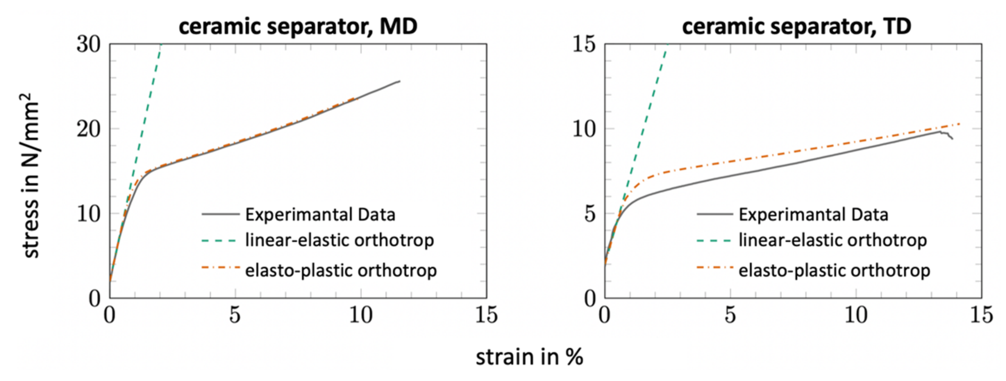
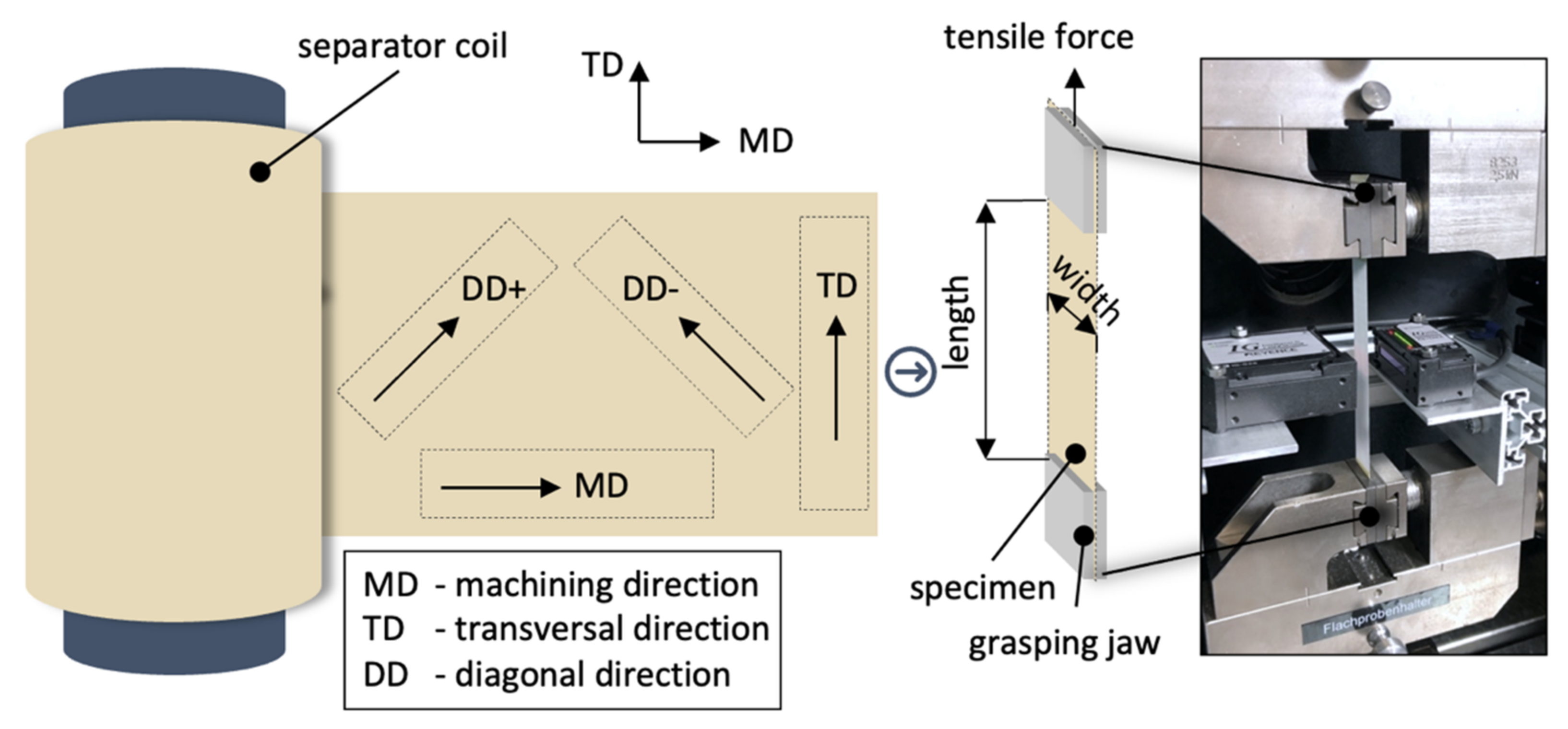
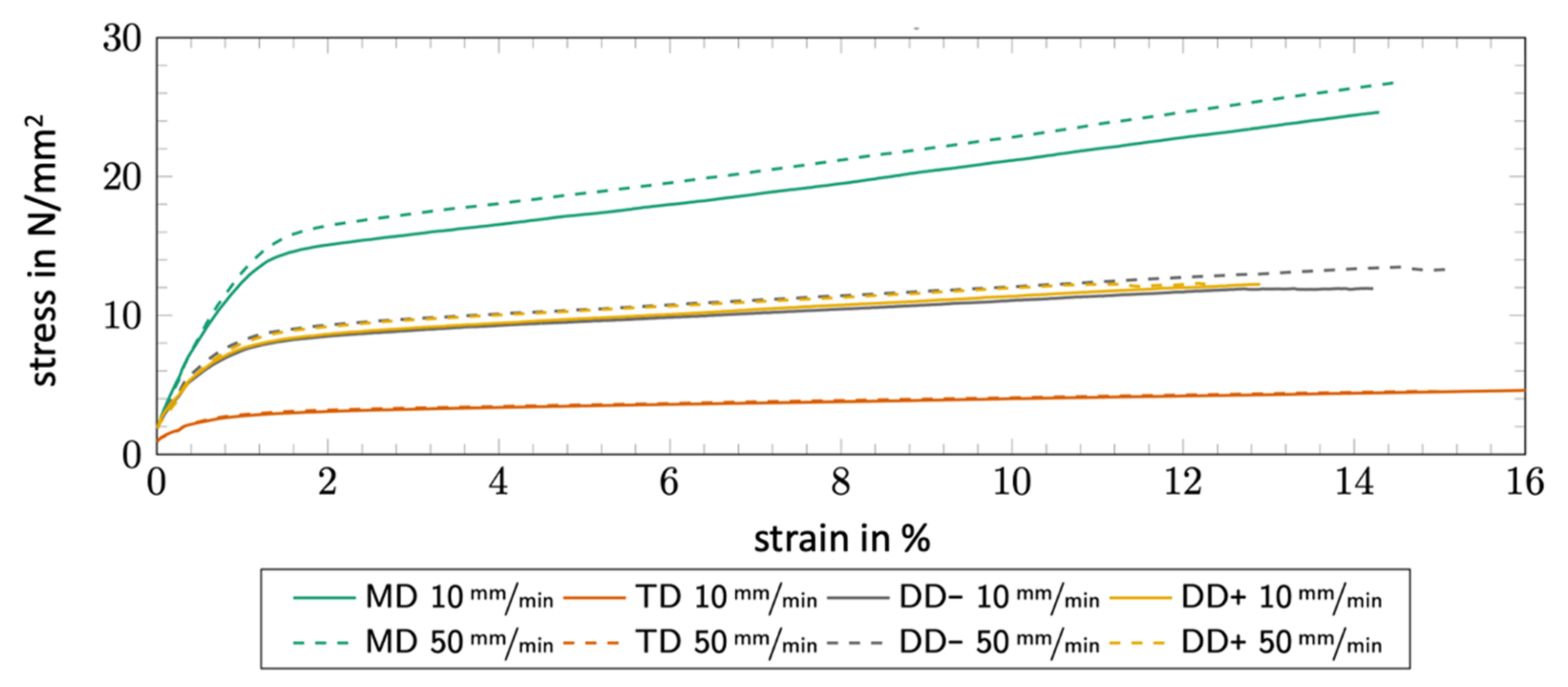
- At the meso scale, properties of individual elements (anodes, cathodes and separators) are investigated as single homogeneous layers through finite element analysis. On the meso scale, Avdeev et al. investigated the mechanical properties of polymer-based separators and observed a strain-rate dependent material behavior [25]. The investigated separator showed a higher stiffness when the strain rate was increased. The investigations from the state of the art and research have shown that separators are characterized as visco-elastic materials with anisotropic material behavior, but in most cases, they are represented in a simplified way via isotropic linear-elastic or visco-elastic material models.
- In the case of the electrode, investigations primarily consider the interactions of specific loads in the context of the electrochemical performance. For example, Zhu et al. investigated the mechanical degradation of electrodes under electrochemical–mechanical conditions with the help of a homogeneous layered electrode model and a finite element software [26]. Mooy investigated different load cases on the electrode caused by different handling processes to align electrodes [6].
- The macro scale investigates the ESC up to complete battery cells including electrolyte and housing. A distinction is made between the simplified representation as a homogeneous material and the detailed heterogeneous representation of the individual elements considering multi-layer interactions.This research field contains various investigations on the characterization of the mechanical properties of electrodes and separators. Kermani and Sahraei give an overview of previous activities on experimental characterization and numerical simulation by using FEA [27].
- The system scale is used to investigate the structural properties at battery module or system level. Thomitzek et al. investigate the effects of quality fluctuations of individual processes on the battery cell [14]. In addition to the individual process, the effects on the battery cell through the subsequent processes are considered. Accordingly, intermediate product properties are analyzed in coupled process simulations in order to coordinate the individual processes and to obtain the best possible product quality. The production processes were described by mathematical and empirical models, whereby the battery cell was simulated by the widely used pseudo-two-dimensional (P2D) model [28]. The knowledge gained from these simulations subsequently enabled the optimal dimensioning of these processes and revealed process limits [14]. Although a general approach was developed, the simulation of the production process was limited to electrode production with a special focus on calendaring.
2. Materials and Methods
3. Results
3.1. HoLiB–High Throughput Processes for the Production of Lithium Ion Batteries
3.1.1. General Process Description
3.1.2. Reasons for Simulation-Based Process Modelling
3.1.3. Disadvantages of an Empirical Approach
3.1.4. HoLiB—Separating Module
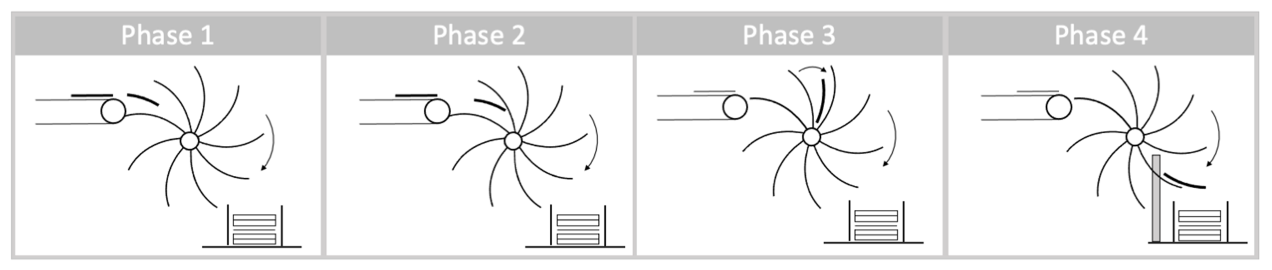
3.1.5. HoLiB—Paddle Wheel
3.2. KontiBat—Productivity Increased Z-Folding Ies Using Continuous Processes
3.2.1. General Process Description
3.2.2. Reasons for Simulation-Based Process Modelling
3.2.3. Disadvantages of an Empirical Approach
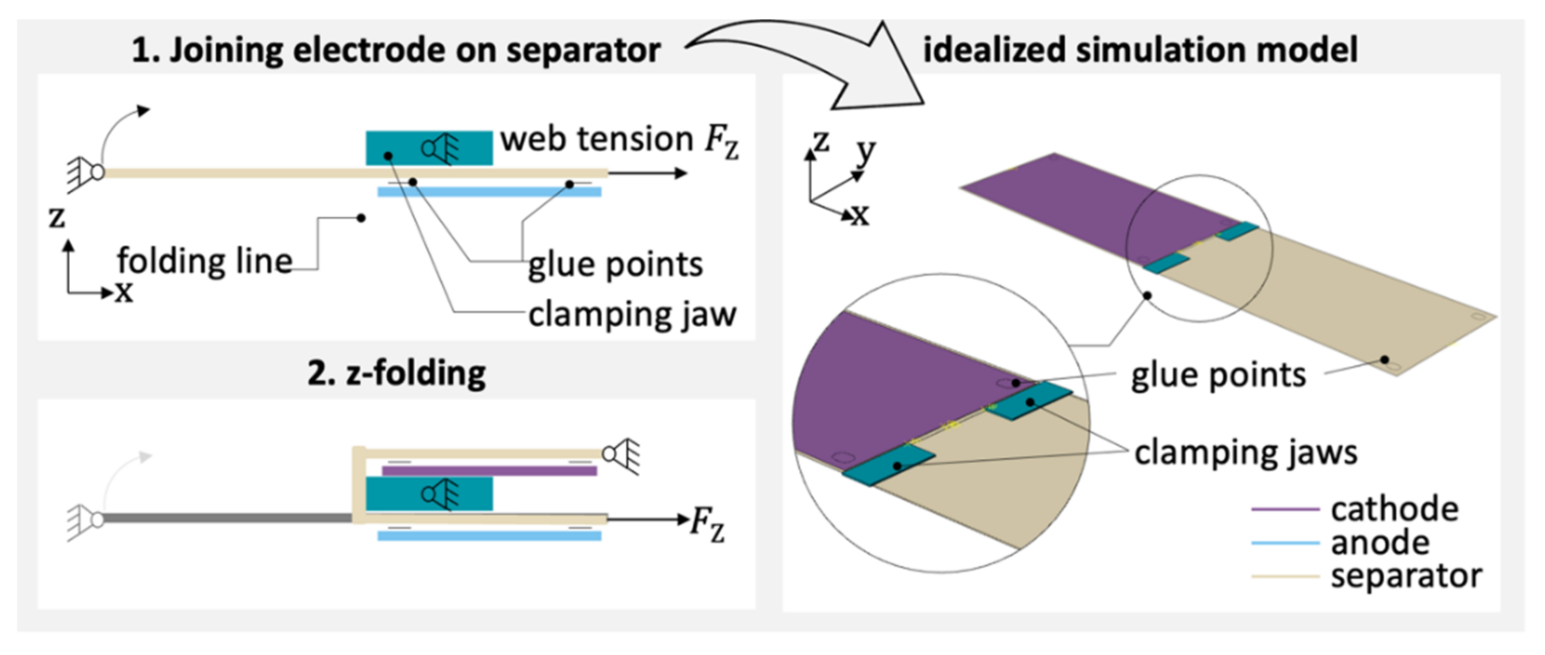
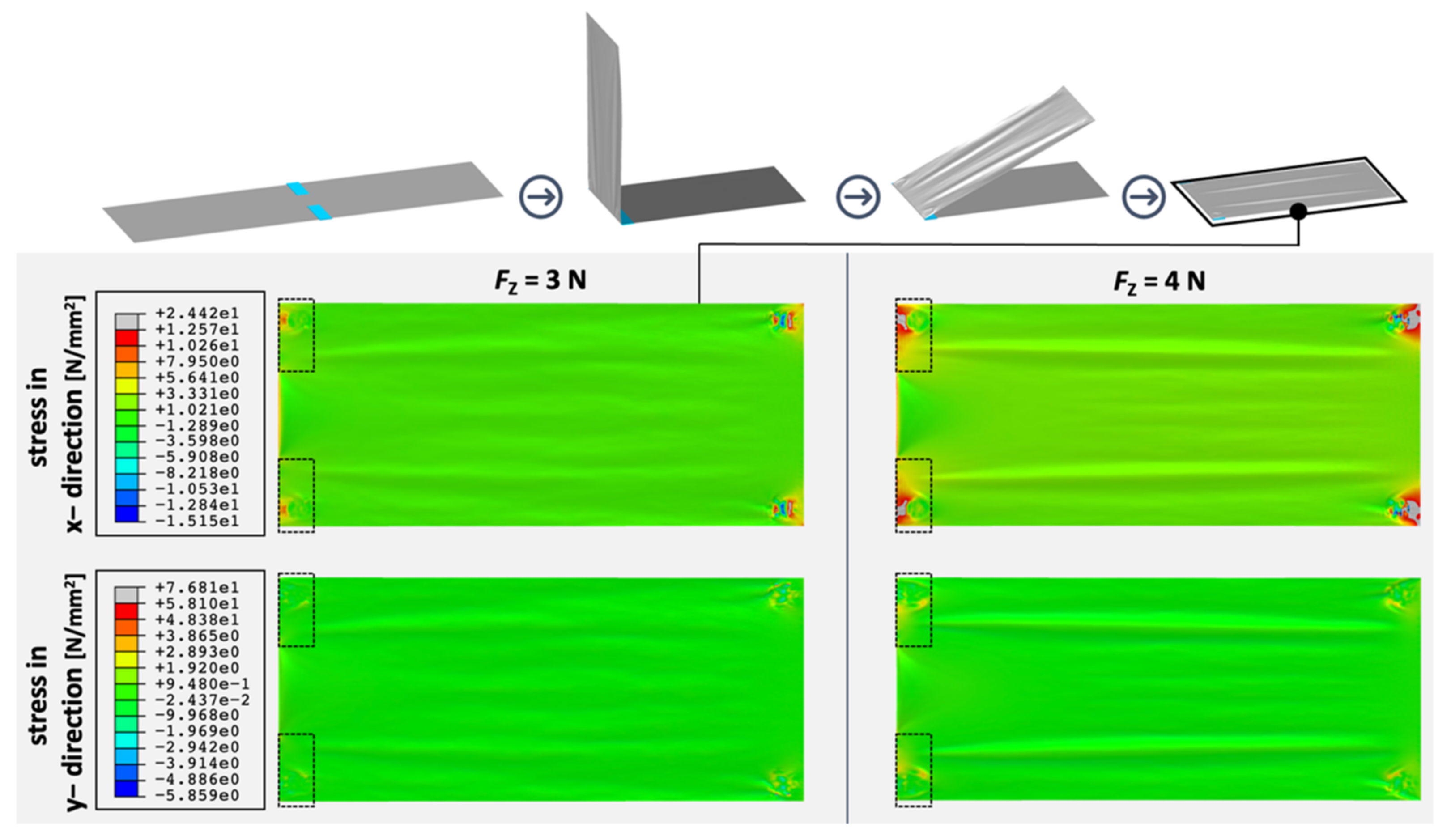
3.2.4. KontiBat–Z-Folding Process
- The idealized model considers the process of folding a strip of separator with a total length equal to twice the battery cell length (2 × 304 mm).
- The separator is clamped at one end with web tension acting at the other end.
- The clamping jaws of the gripper are positioned at the region of the separator to be folded (folding line).
- Different engagement depths are controlled by the length of the clamping jaws.
- One anode and cathode are arranged alternately on each side of the separator.
- The adhesive connection is modeled simplified as a rigid connection between separator and electrode. A total of four glue points are provided for each electrode.
4. Discussion
5. Conclusions
Author Contributions
Funding
Data Availability Statement
Conflicts of Interest
Appendix A
References
- Forum, W.E. Global Battery Demand between 2018 and 2030, by Application (in Gigawatt Hours); Statista. Available online: https://www.statista.com/statistics/1103218/global-batterydemand-forecast (accessed on 25 October 2021).
- Kwade, A.; Haselrieder, W.; Leithoff, R.; Modlinger, A.; Dietrich, F.; Droeder, K. Current status and challenges for automotive battery production technologies. Nat. Energy 2018, 3, 290–300. [Google Scholar] [CrossRef]
- Schröder, R.; Aydemir, M.; Seliger, G. Comparatively assessing different shapes of lithium-ion battery cells. Procedia Manuf. 2017, 8, 104–111. [Google Scholar] [CrossRef]
- Kampker, A. Elektromobilproduktion; Springer: Berlin/Heidelberg, Germany, 2014. [Google Scholar]
- Aydemir, M.; Glodde, A.; Mooy, R.; Bach, G. Increasing productivity in assembling z-folded electrode-separator-composites for lithium-ion batteries. CIRP Ann. 2017, 66, 25–28. [Google Scholar] [CrossRef]
- Mooy, R.J.M. Beitrag zur Produktivitätssteigerung in der Vereinzelung, Positionierung und Orientierung von Elektrodenfolien durch eine Kontinuierliche Materialbewegung. Ph.D. Thesis, Technische Universität Berlin, Berlin, Germany, 2019. [Google Scholar]
- Bach, G. Beitrag zur Produktivitätssteigerung in der Massenherstellung von Lithium-Ionen-Batteriezellen. Ph.D. Thesis, Technische Universität Berlin, Berlin, Germany, 2017. [Google Scholar]
- Aydemir, M. Modellbasierte Prozessgrenzenermittlung in der Entwicklung und Inbetriebnahme von Hochdurchsatz-Batteriestapelverfahren. Ph.D. Thesis, Technische Universität Berlin, Berlin, Germany, 2021. [Google Scholar]
- Edström, K. Roadmap Battery 2030+—Inventing the Sustainable Batteries of the Future. Available online: https://battery2030.eu/digitalAssets/860/c_860904-l_1-k_roadmap-27-march.pdf (accessed on 25 October 2021).
- Deutskens, C. Battery-News.de im Gespräch mit Prof. Dr. Fritz Klocke. Available online: https://battery-news.de/index.php/2020/03/08/prof-klocke-die-prozessablaeufe-werden-ueber-standardisierte-schnittstellen-realisiert-um-ganz-dezidiert-der-deutschen-industrie-moeglichkeiten-zu-geben-eigene-anlagentechniken-zu-entwickeln-zu/ (accessed on 25 October 2021).
- Thiede, S.; Turetskyy, A.; Kwade, A.; Kara, S.; Herrmann, C. Data mining in battery production chains towards multi-criterial quality prediction. CIRP Ann. 2019, 68, 463–466. [Google Scholar] [CrossRef]
- Turetskyy, A.; Thiede, S.; Thomitzek, M.; Drachenfels, N.; Pape, T.; Herrmann, C. Toward Data-Driven Applications in Lithium-Ion Battery Cell Manufacturing. Energy Technol. 2020, 8, 1900136. [Google Scholar] [CrossRef] [Green Version]
- Turetskyy, A.; Wessel, J.; Herrmann, C.; Thiede, S. Data-driven cyber-physical System for Quality Gates in Lithium-ion Battery Cell Manufacturing. Procedia CIRP 2020, 93, 168–173. [Google Scholar] [CrossRef]
- Thomitzek, M.; Schmidt, O.; Röder, F.; Krewer, U.; Herrmann, C.; Thiede, S. Simulating Process-Product Interdependencies in Battery Production Systems. Procedia CIRP 2018, 72, 346–351. [Google Scholar]
- Brodd, R.J.; Helou, C. Cost comparison of producing high-performance Li-ion batteries in the U.S. and in China. J. Power Sources 2013, 231, 293–300. [Google Scholar]
- Wood, D.L.; Li, J.; Daniel, C. Prospects for reducing the processing cost of lithium ion batteries. J. Power Sources 2015, 275, 234–242. [Google Scholar] [CrossRef] [Green Version]
- Chinnathai, M.K.; Alkan, B.; Vera, D.; Harrison, R. Pilot to full-scale production: A battery module assembly case study. Procedia CIRP 2018, 72, 796–801. [Google Scholar] [CrossRef]
- Brinksmeier, E.; Aurich, J.; Govekar, E.; Heinzel, C.; Hoffmeister, H.-W.; Klocke, F.; Peters, J.; Rentsch, R.; Stephenson, D.; Uhlmann, E.; et al. Advances in Modeling and Simulation of Grinding Processes. CIRP Ann. 2006, 55, 667–696. [Google Scholar]
- Klocke, F.; Stauder, J.; Mattfeld, P.; Müller, J. Modeling of Manufacturing Technologies During Ramp-up. Procedia CIRP 2016, 51, 122–127. [Google Scholar]
- Colledani, M.; Tolio, T.; Yemane, A. Production quality improvement during manufacturing systems ramp-up. CIRP J. Manuf. Sci. Technol. 2018, 23, 197–206. [Google Scholar] [CrossRef]
- Zhu, J.; Wierzbicki, T.; Li, W. A review of safety-focused mechanical modeling of commercial lithium-ion batteries. J. Power Sources 2018, 378, 153–168. [Google Scholar] [CrossRef]
- Westermeier, M. Qualitätsorientierte Analyse Komplexer Prozessketten am Beispiel der Herstellung von Batteriezellen; Nr. 322 in Dissertation; Forschungsberichte iwb Herbert Utz Verlag: München, Germany, 2016. [Google Scholar]
- Weinmann, H. Influences of increasing coating thicknesses and calendering degrees on single sheet stack formation. Presented at the International Battery Production Conference (IBPC), Braunschweig, Germany, 4–6 November 2019. [Google Scholar]
- Sangrós Giménez, C.; Finke, B.; Nowak, C.; Schilde, C.; Kwade, A. Structural and mechanical characterization of lithium-ion battery electrodes via DEM simulations. Adv. Powder Technol. 2018, 29, 2312–2321. [Google Scholar]
- Avdeev, I.V.; Martinsen, M.J.; Francis, A.B. Materials Testing of a Lithium Ion Battery Separator for use in Finite Element Analysis. In Proceedings of the ASME 2012 International Mechanical Engineering Congress & Exposition (IMECE2012), Houston, TX, USA, 9–15 November 2012. [Google Scholar]
- Zhu, X.; Xie, Y.; Chen, H.; Luan, W. Numerical analysis of the cyclic mechanical damage of Li-ion battery electrode and experimental validation. Int. J. Fatigue 2021, 142, 105915. [Google Scholar]
- Kermani, G.; Sahraei, E. Review: Characterization and Modeling of the Mechanical Properties of Lithium-Ion Batteries. Energies 2017, 10, 1730. [Google Scholar] [CrossRef] [Green Version]
- Schmidt, O.; Thomitzek, M.; Röder, F.; Thiede, S.; Herrmann, C.; Krewer, U. Modeling the Impact of Manufacturing Uncertainties on Lithium-Ion Batteries. J. Electrochem. Soc. 2020, 167, 060501. [Google Scholar] [CrossRef]
- Kaiser, J.; Wenzel, V.; Nirschl, H.; Bitsch, B.; Willenbacher, N.; Baunach, M.; Schmitt, M.; Jaiser, S.; Scharfer, P.; Schabel, W. Prozess- und Produktentwicklung von Elektroden für Li-Ionen-Zellen. Chem. Ing. Tech. 2014, 86, 695–706. [Google Scholar] [CrossRef]
- Mayer, J.K.; Almar, L.; Asylbekov, E.; Haselrieder, W.; Kwade, A.; Weber, A.; Nirschl, H. Influence of the Carbon Black Dispersing Process on the Microstructure and Performance of Li-Ion Battery Cathodes. Energy Technol. 2020, 8, 1900161. [Google Scholar] [CrossRef]
- Schreiner, D.; Klinger, A.; Reinhart, G. Modeling of the Calendering Process for Lithium-Ion Batteries with DEM Simulation. Procedia CIRP 2020, 93, 149–155. [Google Scholar] [CrossRef]
- Ngandjong, A.; Lombardo, T.; Primo, E.; Chouchane, M.; Shodiev, A.; Arcelus, O.; Franco, A.A. Investigating Electrode Calendering and its Impact on Electrochemical Performance by Means of a New Discrete Element Method Model: Towards a Digital Twin of Li-Ion Battery Manufacturing. J. Power Sources 2021, 485, 229320. [Google Scholar] [CrossRef]
- Gausemeier, J.; Moehringer, S. VDI 2206-a new guideline for the design of mechatronic systems. IFAC Proc. Vol. 2002, 35, 785–790. [Google Scholar] [CrossRef]
- Stommel, M.; Stojek, M.; Korte, W. FEM zur Berechnung von Kunststoff-Und Elastomerbauteilen; Hanser: München, Germany, 2018. [Google Scholar]
- Haselrieder, W.; Westphal, B.; Bockholt, H.; Diener, A.; Höft, S.; Kwade, A. Measuring the coating adhesion strength of electrodes for lithium-ion batteries. Int. J. Adhes. Adhes. 2015, 60, 1–8. [Google Scholar] [CrossRef]
- Bockholt, H.; Indrikova, M.; Netz, A.; Golks, F.; Kwade, A. The interaction of consecutive process steps in the manufacturing of lithium-ion battery electrodes with regard to structural and electrochemical properties. J. Power Sources 2016, 325, 140–151. [Google Scholar] [CrossRef]
- Aydemir, M.; Müller, A.; Glodde, A.; Seliger, G. Greifsystem für die z-Faltende Zellverbundherstellung des Elektrode-Separator-Verbunds einer Batteriezelle; wt-Werkstattstechnik Online 108(9); Springer: Düsseldorf, Germany, 2018. [Google Scholar]
- Von Boeselager, C.; Müller, A.; Helm, J.; Brodhun, J.; Glodde, A.; Olowinsky, A.; Leithoff, R.; Fröhlich, A.; Kandula, M.; Dietrich, F.; et al. A Novel High-Throuput Process for the Production of Lithium Ion. Battery Cells; wt Werkstatttechnik Online 110(9); Springer: Düsseldorf, Germany, 2020. [Google Scholar]
- Fleischer, J.; Ruprecht, E.; Baumeister, M.; Haag, S. Automated Handling of Limp Foils in Lithium-Ion-Cell Manufacturing. In Proceedings of the 19th CIRP Conference on Life Cycle Engineering, Berkeley, CA, USA, 23–25 May 2012. [Google Scholar]
- Hu, J.; Li, L.; Zhou, P.; Li, G.; Sun, Q. Co-simulation and Analysis of Radar Skeleton Based on ANSYS and ADAMS. In Proceedings of the International Conference on Mechanical Design; Springer: Singapore, 2017. [Google Scholar]
- Li, N.; Yang, Z.; Huang, H.; Zhang, G. The dynamic simulation of robotic tool changer based on adams and ansys. In Proceedings of the International Conference on Cybernetics, Robotics and Control (CRC), Hong Kong, China, 19–26 August 2016. [Google Scholar]
- Frimpong, S. Contact and Joint Forces Modeling and Simulation of Crawler-formation Interactions. J. Powder Metall. Min. 2015, 4, 135. [Google Scholar]
- Zhang, G.; Xie, Q.; Zhu, S.; Zhang, Y. Flexible Multibody Dynamics of Sewing Machine with Multi-Clearance Joints. In WCX™ 17: SAE World Congress Experience; SAE Technical Paper Series; SAE International: Detroit, MI, USA, 2017. [Google Scholar]
- Sapietová, A.; Gajdoš, L.; Dekýš, V.; Sapieta, M. Analysis of the Influence of Input Function Contact Parameters of the Impact Force Process in the MSC ADAMS. In Ryszard Jabłoński und Tomas Brezina (Hg.): Advanced Mechatronics Solutions, Bd. 393; Springer International Publishing: Cham, Switzerland, 2016. [Google Scholar]
- Aydemir, M.; Mooy, R.; Glodde, A.; Seliger, G. Fügen von Elektrodenfolien in der Batteriezellherstellung. ZWF Z. Wirtsch. Fabr. 2017, 112, 684–689. [Google Scholar]
- Glodde, A. Kinematische Modellierung eines Kontinuierlichen z-Faltprozesses für die Batterieproduktion. Ph.D. Dissertation, Technische Universität Berlin, Berlin, Germany, 2020. [Google Scholar]
- Dietrich, F.; Glodde, A.; Solmaz, S. Accuracy analysis and improvement method for continuous web-based precision assembly. CIRP Ann. 2020, 69, 5–8. [Google Scholar] [CrossRef]
- Zhang, X.; Sahraei, E.; Wang, K. Deformation and failure characteristics of four types of lithium-ion battery separators. J. Power Sources 2016, 327, 693–701. [Google Scholar] [CrossRef]
- Hill, R. A theory of the yielding and plastic flow of anisotropic metals. Proc. R. Soc. Lond. Ser. A Math. Phys. Sci. 1948, 193, 281–297. [Google Scholar]
- Müller, A.; Aydemir, M.; Dietrich, F. Decision Support Based on Cost and Risk Estimation to Prioritize Battery Cell Assembly Technologies Report; Technische Universität Berlin: Berlin, Germany, 2021. [Google Scholar]
- Seliger, G. Sustainable manufacturing for global value creation. In Sustainable Manufacturing; Springer: Berlin/Heidelberg, Germany, 2012; pp. 3–8. [Google Scholar]


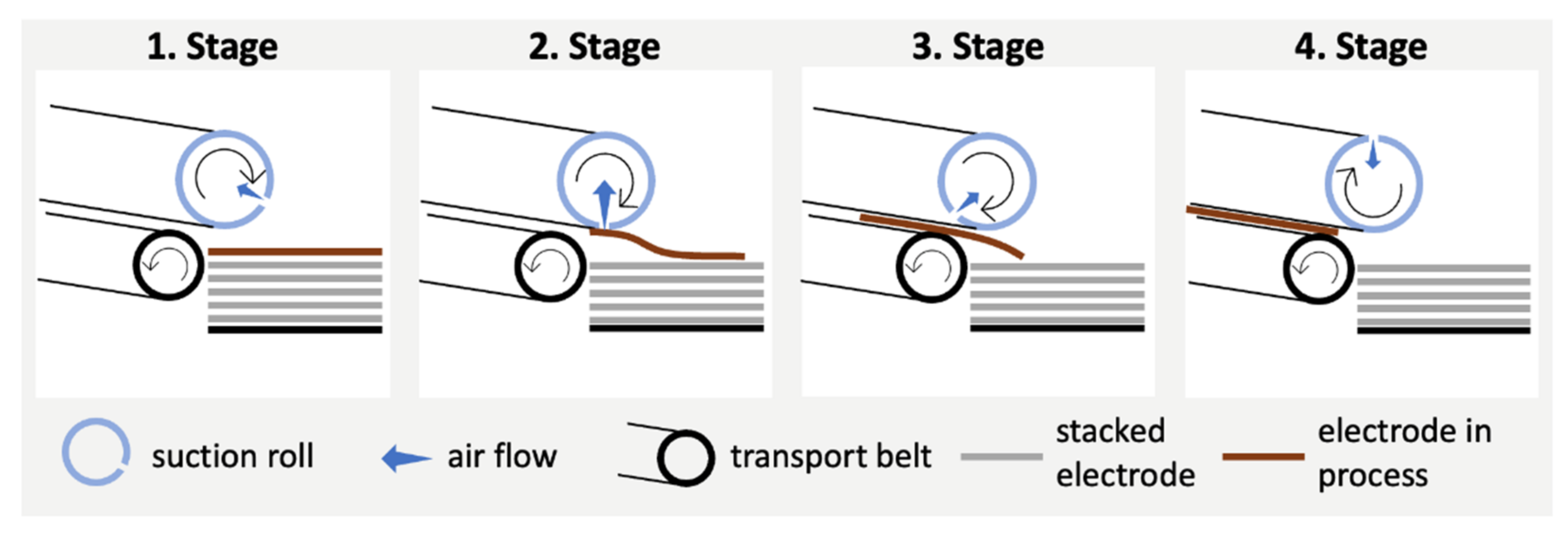
| Overview of the Loads on Electrode per Stage | |
|---|---|
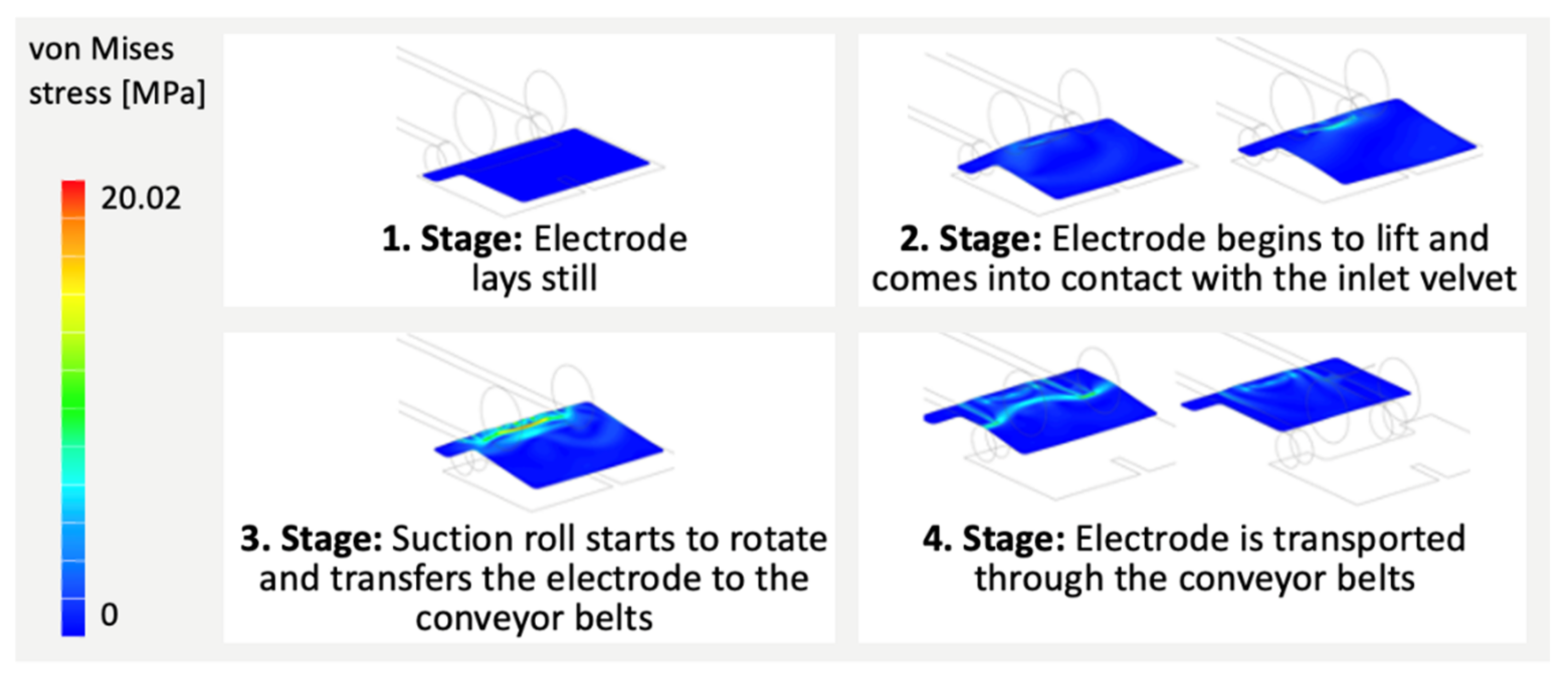
| 1. Stage | No loads. |
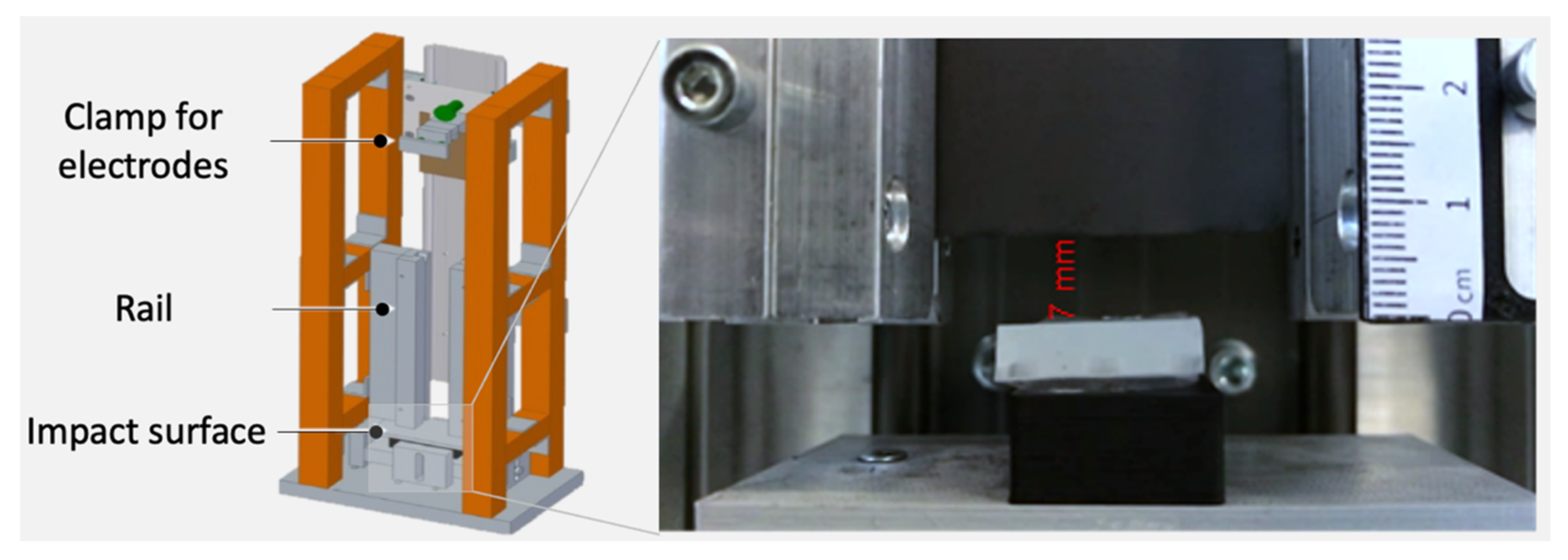
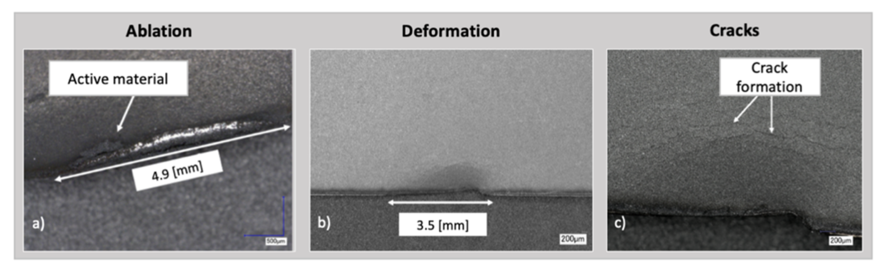
| 2. Stage | Bending loads occur through the upward movement of the electrode. Tensile force on the suction area through the suction roll. The impact of the electrode on the suction inlet of the vacuum roll can lead to local chipping of the coating and to deformations. |
| 3. Stage | Tensile force in the conveying direction occurs due to the acceleration of the vacuum roll and the mass inertia of the electrode. Impact loading occurs when the leading edge of the electrode hits the belt drive but does not optimally hit the slit. This can lead to chipping at the leading edge of the electrode. |
| 4. Stage | Deformations can lead to shear stresses, which may occur due to a badly synchronized movement of the electrode to the conveyor belt. In case of large deformations, delamination and collisions with the machinery occur. |
| Material of Impact Surface | Coefficient of Restitution |
|---|---|
| Aluminum | 0.04 |
| PLA + Silicone 45 ShA | 0.15 |
| PLA + Silicone 13 ShA | 0.22 |
| Tribological System | Static Friction Coefficient | Dynamic Friction Coefficient |
|---|---|---|
| Aluminum/Anode | 0.25 | 0.19 |
| Aluminum/Cathode | 0.3 | 0.26 |
| Silicone 45 ShA/Anode | 0.87 | 0.75 |
| Silicone 45 ShA/Cathode | 0.99 | 0.8 |
| POM/Anode | 0.24 | 0.17 |
| POM/Cathode | 0.29 | 0.23 |
Publisher’s Note: MDPI stays neutral with regard to jurisdictional claims in published maps and institutional affiliations. |
© 2021 by the authors. Licensee MDPI, Basel, Switzerland. This article is an open access article distributed under the terms and conditions of the Creative Commons Attribution (CC BY) license (https://creativecommons.org/licenses/by/4.0/).
Share and Cite
Müller, A.; Aydemir, M.; von Boeselager, C.; van Ohlen, N.; Rahlfs, S.; Leithoff, R.; Dröder, K.; Dietrich, F. Simulation Based Approach for High-Throughput Stacking Processes in Battery Production. Processes 2021, 9, 1993. https://doi.org/10.3390/pr9111993
Müller A, Aydemir M, von Boeselager C, van Ohlen N, Rahlfs S, Leithoff R, Dröder K, Dietrich F. Simulation Based Approach for High-Throughput Stacking Processes in Battery Production. Processes. 2021; 9(11):1993. https://doi.org/10.3390/pr9111993
Chicago/Turabian StyleMüller, Alexander, Muhammed Aydemir, Christina von Boeselager, Nils van Ohlen, Sina Rahlfs, Ruben Leithoff, Klaus Dröder, and Franz Dietrich. 2021. "Simulation Based Approach for High-Throughput Stacking Processes in Battery Production" Processes 9, no. 11: 1993. https://doi.org/10.3390/pr9111993
APA StyleMüller, A., Aydemir, M., von Boeselager, C., van Ohlen, N., Rahlfs, S., Leithoff, R., Dröder, K., & Dietrich, F. (2021). Simulation Based Approach for High-Throughput Stacking Processes in Battery Production. Processes, 9(11), 1993. https://doi.org/10.3390/pr9111993