Article

Research on Dynamic Modeling of the Supercritical Carbon Dioxide Power Cycle

1
Key Laboratory of Thermal Power Technology, Wuhan 430064, China
2
Wuhan Second Ship Design and Research Institute, Wuhan 430064, China
*
Author to whom correspondence should be addressed.
Processes 2021, 9(11), 1946; https://doi.org/10.3390/pr9111946
Submission received: 2 September 2021 / Revised: 17 October 2021 / Accepted: 27 October 2021 / Published: 29 October 2021
(This article belongs to the Special Issue Integrated Energy Systems towards Carbon Neutrality)

Abstract

:
The supercritical carbon dioxide (SCO2) Brayton cycle, as a substitute for the steam cycle, can be widely used in a variety of power generation scenarios. However, most of the existing SCO2 cycle studies are restricted to basic thermodynamics research, parameter optimizations, system design in different application fields, and even economic analysis. Considering the load variability and control flexibility of the power generation system, the dynamic performance research of the SCO2 cycle is also crucial, but the work done is still limited. Based on the previous studies, Simulink software is used in this paper to develop a dynamic model of the 20 MW-SCO2 recompression cycle, which specifically includes component models that can independently realize physical functions and an overall closed-loop cycle model. A series of comparative calculation are carried out to verify the models and the results are very positive. The SCO2 recompression power system is built with the developed models and the dynamic model runs stably with a maximum error of 0.56%. Finally, the simulation of the dynamic switching conditions of the 20 MW-SCO2 recompression cycle are performed and the analysis results supply instructive suggestions for the system operation and control.

1. Introduction

The supercritical carbon dioxide (SCO2) cycle can be traced back to the 1960s, after which research on the cycle was temporarily shelved due to technical limitations [1]. As the fourth-generation nuclear reactor developed rapidly in the 21st century, the operating temperature now reaches as high as 500–900 °C. Considering that the material reliability of the ultra-supercritical steam cycle cannot be guaranteed [2], the SCO2 Brayton cycle as an alternative cycle has attracted widespread attention from scholars. Additionally, comparative studies on the SCO2 cycle, steam cycle, and helium cycle have also been carried out [3,4]. A large number of results show that the SCO2 cycle is more suitable for higher temperature nuclear reactors due to the simple structure and high efficiency, and has the potential to reduce costs.
The SCO2 cycle also has the advantages of a compact structure and good heat source matching performance, and can be widely used in nuclear energy [5,6,7], waste heat recovery [8,9,10], solar energy [11,12,13], and thermal power [14,15,16]. A lot of work has been done on the basic thermodynamic research of the SCO2 cycle, configuration and parameter optimizations, system design in different application fields, and even economic analysis and optimization.
Sarkar [17] performed second-law analysis of the SCO2 cycle, and the results showed that the minimum operating temperature has a greater impact on the optimal pressure ratio and cycle efficiency than the maximum operating temperature, and the irreversibility of heat exchangers is significantly higher than that of turbomachinery. AHN et al. [18] found that the recompression cycle showed the highest efficiency by comparing different cycle layouts. Moreover, the recompression cycle can effectively avoid the recuperator pinch point, which is more likely to occur in the simple recuperation cycle [19]. Ma et al. [20] analyzed the SCO2 cycle with an intercooling system of the main compressor, and studied the influence of the pressure ratio and the pressure distribution of the two compression stages on the performance of the system. The results show that the coupled main compressor intercooling system can improve the cycle efficiency, save system cost, and improve cycle stability. Liu et al. [14] studied the effects of the reheat stages on the cycle efficiency. Li et al. [21] conceptually designed the power system of the SCO2 cycle coupled with a small lead-cooled fast reactor, and analyzed the thermodynamic and economic performance. In addition, some scholars have conceptually designed the configurations of SCO2 coal-fired power plants with different loads, and proposed a series of SCO2 boiler and cycle-side temperature coupling methods to rationally utilize the flue gas heat [15,22,23]. Zhu et al. [24] used the weighted quality method to evaluate the cost of an SCO2 boiler, and then evaluated the cost of SCO2 coal-fired power generation, which shows the economic advantages of the SCO2 cycle in the thermal power field. At the same time, a large quantity of related research has also been carried out in the fields of solar energy and waste heat recovery [25,26].
The above research has mainly focused on the steady state calculation. Since the SCO2 cycle is used in the power generation system, attention needs to be focused on the performance of a variable load and flexibility. Thus, research on the performance and simulation of the SCO2 cycle has also attracted attention from all over the world [27]. Dyreby [28] studied the method of SCO2 Brayton cycles numerical modelling. Mois-seytsev and Sienicki [29] simulated the performance characteristics of the 100 kW simple recuperated Brayton cycle configuration by developing The Plant Dynamics Code (PDC). Wu P. et al. [30] and Deng T. et al. [31] also developed the transient analysis code for the SCO2 Brayton cycle.
As a supplement to the previous research, this paper studies the dynamic performance of the SCO2 recompression cycle of a 20 MW sodium-cooled reactor with Simulink software.

2. System Configuration and Modeling Descriptions

The power generation system described in this paper adopts the SCO2 recompression cycle, and the configuration is shown in Figure 1. The overall system includes a turbine (T), main compressor (MC), re-compressor (RC), high-temperature and low-temperature recuperators (HTRs and LTRs), intermediate heat exchanger (IHE), pre-cooler (PC), surge tank (ST), and heater.
As shown in Figure 1, the high-temperature and high-pressure CO2 from the IHE enters the turbine to do work and generates electricity. The exhausted CO2 from turbine flows into the HTR and LTR and releases heat. The low-pressure fluid at the LTR outlet is then split into two streams: one stream is cooled in the PC and then compressed in the MC, and the other stream is directly compressed in the RC. Two streams converge at the high-pressure side outlet of LTR and are sent to the HTR and IHE for heating.
In order to meet the flexible control requirements, the MC, RC, and turbine adopt a split-axis layout. At the same time, the ST is arranged between the PC and the MC to facilitate the control of the MC inlet pressure and buffer the pressure change. The ST is connected with a CO2 storage tank, and the MC inlet pressure is maintained above the critical point by controlling the amount of CO2 in the ST.
This paper focuses on exploring the dynamic characteristics of the SCO2 recompression cycle, and the mathematical model of each component is developed to reflect the dominant characteristics of the cycle. The model of each component could be able to realize independent physical functions and be mathematically independent. At the same time, there are clear boundaries and data interfaces between the modules. The internal parameters of the models can be changed according to actual needs, and the impact of each parameter on the overall circulatory system can be analyzed. Based on the above requirements, this paper develops the dynamic model of the SCO2 system based on the Simulink platform, which is also convenient for system control strategy research.

3. Dynamic Model Development

3.1. Heat Exchanger Model

The heat exchangers involved in the SCO2 power cycle, including HTR, LTR, PC, and IHE, adopt printed circuit heat exchangers (PCHEs), which have great advantages in dynamic modeling due to the regular layout structure. The flow and heat transfer model of PCHEs are based on the three conservation equations of mass, momentum, and energy, which can be simplified to one-dimensional models. The structure of PCHE is shown in Figure 2a.
In this section, PCHE is divided into several parts, and the flow and heat transfer models are established for each part, as shown in Figure 2b. Assuming that the fluid in each part is incompressible, the steady-state model is adopted to describe the flow process. In each part, the lumped parameter method is applied to the calculation and the fluids and wall are treated as zero-dimensional nodes. The heat transfer processes between the cold fluid and the wall, the wall, and the hot fluid are considered, while the heat transfer in the direction of the fluid flow is ignored to ensure the accuracy and simplification of the calculation process. The specific calculation process is as follows [32,33].
Hot fluid:
V h ρ h c p , h d T h d t + m h ( h h out h h in ) = ( k A s ) h ( T h T w )
Cold fluid:
V c ρ c c p , c d T c d t + m c ( h c out h c in ) = ( k A s ) c ( T w T c )
Wall:
m w c p , w d T w d t = ( h A s ) h ( T h T w ) ( h A s ) c ( T w T c )
The heat transfer coefficient calculation methods of different heat exchangers are selected based on the fluid type and Reynolds number (Re). For example, the Gnielinski formula is applied to calculate the Nusselt number (Nu) of the cold and hot side fluids in HTR and LTR, as shown in Equations (4) and (5). The cold and hot side of HTR and LTR are both CO2, so the Nusselt number (Nu) can be calculated by the Gnielinski formula. Thus, the heat transfer coefficient can be obtained. The specific heat capacity of the tube wall is determined by the material type:
f = ( 1.82 lg R e 1.64 ) 2
N u = ( f / 8 ) ( R e 1000 ) P r 1 + 12.7 ( P r 2 / 3 1 ) f / 8
where P r is the Prandtl number of the fluid.
The pressure drop of each part can be determined by Equation (6). The pressure drop is proportional to the square of the flow rate and inversely proportional to the fluid density:
Δ P = γ · m 2 ρ
where γ is the effective loss coefficient, which is determined by the pipeline characteristics and can be calculated with the parameters of the design condition.

3.2. Compressor Model

The dynamic response time of different processes and equipment in the SCO2 power cycle is significantly different. The devices with a long response time adopt dynamic-state models, such as recuperators, coolers, etc. On the contrary, the devices and thermal processes with a short response time adopt steady-state models, such as turbine, compressors, working fluid separation, and mixing processes.
The compressor outlet parameters are determined by the inlet parameters and isentropic efficiency. Taking the main compressor (MC), for example, the specific calculation is shown as follows [34]:
h MC , in = h ( T MC , in , P MC , in )
s MC , in = s ( T MC , in , P MC , in )
h MC , out , is = h ( s MC , in , P MC , out )
h MC , out = h MC , in + ( h MC , out , is h MC , in ) / η MC , is
where h MC , in is the MC inlet-specific enthalpy, kJ/kg; h MC , out is the MC outlet-specific enthalpy, kJ/kg; h MC , out , is is the isentropic-specific enthalpy of the MC outlet, kJ/kg; and η MC , is is the isentropic efficiency of the MC.
The outlet pressure and isentropic efficiency of the compressor are provided by the performance prediction curves. The curves describe the relationship between the outlet pressure and efficiency with the mass flow rate and rotating speed. The main compressor performance prediction curves are shown in Figure 3. The re-compressor performance prediction curves are shown in Figure 4, which are obtained through the simulation results based on the compressor design value [35].
It can be seen from the recompression configuration in Figure 1 that the low-pressure side outlet working fluid of the LTR is divided into two streams: one stream is cooled in the PC and then compressed in the MC, while the other stream is directly compressed in the RC. The split ratio ( S R ) is used to express the share of flow entering the recompressor, as shown in Equation (11):
S R = m RC / m
Therefore, the power consumption of the main compressor is:
W MC = m · ( 1 S R ) · ( h MC , out h MC , in )
The power consumption of the recompressor is:
W RC = m · S R · ( h RC , out h RC , in )
where m is the mass flow rate of the circulation system, kg/s; WMC is the MC power consumption, kW; hRC,in is the RC inlet-specific enthalpy, kJ/kg; hRC,out is the RC outlet-specific enthalpy, kJ/kg; and WRC is the RC power consumption, kW.

3.3. Turbine Model

Similar to the compressor model, the turbine outlet parameters are also determined by the inlet parameters and isentropic efficiency. The specific calculation is as follows [29]:
h tur , in = h ( t tur , in , p tur , in )
s tur , in = s ( t tur , in , p tur , in )
h tur , out , is = h ( s tur , in , p tur , out )
h tur , out = h tur , in ( h tur , in h tur , out , is ) · η tur , is
where htur,in is the turbine inlet-specific enthalpy, kJ/kg; htur,out is the turbine outlet-specific enthalpy, kJ/kg; htur,out is the turbine outlet isentropic-specific enthalpy, kJ/kg; and ηtur is the isentropic efficiency of the turbine.
The turbine output power is calculated as follows:
W tur = m tur · ( h tur , in h tur , out )
where mtur is the turbine flow rate, kg/s; and Wtur is turbine output power, kW.
The turbine performance prediction curves are shown in Figure 5 [35].

3.4. Other Models

3.4.1. Surge Tank (ST) Model

In this section, considering the rapid response of pressure, the volume in the entire loop composed of HTR hot end-LTR hot end-PC hot end-ST is lumped into the surge tank to calculate the pressure change. Additionally, it is considered that the working fluid flow rate before and after the HTR hot end, LTR hot end, and PC hot end remains unchanged.
According to the mass conservation equation, the density change of the working fluid in the surge tank is as follows:
d ρ ST d t = m HTR , h m RC + m CFP m PRV m MC V HTR + V LTR + V PC + V ST
where ρST is the working fluid density in the surge tank, kg/m3; mHTR,h is the working fluid flow rate at the HTR hot end, kg/s; mCFP is the flow rate from the CO2 filling pump (CFP) into the ST, kg/s; mPRV is the flow rate of the pressure-reducing valve (PRV), kg/s; VHTR is the working fluid volume at the HTR hot end, m3; VLTR is the working fluid volume at the LTR hot end, m3; VPC is the working fluid volume at the PC hot end, m3; and VST is the ST volume, m3.
According to the energy conservation equation, the specific enthalpy change of the working fluid in the surge tank is shown as below [36]:
d h ST d t = m LTR , h h PC , h + m CFP h CFP m PRV h ST m MC h ST ρ ST V ST
where hST is the specific enthalpy of the CO2 in ST, kJ/kg; hPC is the specific enthalpy of the working fluid at the PC hot end, kJ/kg; and hCFP is the specific enthalpy of the CO2 at the CFP outlet, kJ/kg. According to the density ρST and specific enthalpy hST, the temperature TST and pressure PST of the working fluid in surge tank can be obtained by consulting the REFPROP software.

3.4.2. Working Fluid Mixing Process

In the recompression cycle system, there is a node where the working fluid at the LTR cold end is mixed with that at the outlet of RC. According to the equations of mass conservation and energy conservation, the parameters of the mixed working fluid can be calculated as follows [37]:
m HTR , c = m LTR , c + m RC
h HTR , cin = m LTR , c h LTR , cout + m RC h RC , out m HTR , c
where hHTR,cin is the specific enthalpy of the mixed working fluid, kJ/kg; hLTR,cout is the specific enthalpy of the working fluid at the outlet of the LTR cold end, kJ/kg; and hRC,out is the specific enthalpy of the working fluid at the RC outlet, kJ/kg. According to the pressure and specific enthalpy, the temperature of the mixed working fluid can be obtained by consulting the REFPROP software.

4. Model Verification

A series of comparative calculations were carried out to verify the models. Firstly, the main component models were verified with the design values to make sure that the models are built correctly. All component models were connected based on the CO2 flow sequence and system structure, and constitute the overall dynamic model of the power generation system. Then, based on the system design value, we carried out the system steady-state simulation.

4.1. Component Verification

4.1.1. PCHE Model Verification

The structural parameters of the PCHE are shown in Table 1. In the Simulink model, the PCHE was divided into five nodes, and the model was built with the Simulink graphical modeling tool based on the above-mentioned unsteady heat transfer relationship. We obtained the calculation results with the structural parameters and the thermal parameters based on the Simulink model. According to the comparison with the design value, the model calculation accuracy is reliable. As shown in Table 2, the outlet temperature of the hot side error is as small as 0.065%, while that of the cold side is larger, with an error of 0.25%. The results prove that the model has high accuracy.
We also performed the disturbance analysis, and the results were compared with other model data to verify the dynamic simulation capacity of the model. At 300 s, the inlet temperature of the hot fluid increased and decreased by 30 °C, respectively. The characteristics of the outlet temperature of the cold and hot fluids were analyzed and compared with the literature [38]. The comparison results are shown in Figure 6:
The authors of [38] carried out the PCHE thermodynamic analysis and performance prediction of a 1000 MW SCO2 coal-fired power plant with CFD mesh simulation. Although the background and method were different from this paper, the model establishment was similar, being based on the basic conservation equations. As can be seen from the comparison, when affected by the disturbance of the step change in the hot fluid inlet temperature, the changes in the outlet temperature of the cold and hot fluids show similar dynamic characteristics:
(1)
When the inlet temperature of the hot fluid is subject to a step change, the outlet temperature of the cold fluid responds faster. At the same time, the outlet temperature of the cold fluid varies widely, which is equivalent to the change of the disturbance temperature;
(2)
The outlet temperature of the hot fluid is less affected by the inlet temperature and changes slowly after being disturbed. The temperature change is smaller as well.

4.1.2. Compressor Model Verification

According to the mathematical calculation formula and performance curve of the compressor in the steady state, the main compressor and recompressor models were built in Simulink. The calculation of the performance curve in the model adopted the interpolation calculation of the two-dimensional Look up table. The steady state calculation results were compared with the design value to verify the model accuracy. As shown in Table 3, the main compressor outlet temperature error is as large as 1.1%, which is considered acceptable.

4.1.3. Turbine Model Verification

For the turbine, the model build process is similar to the compressor model. The design value was also applied to the verification of the model and the comparison results are shown in Table 4. As can be seen, the largest error is the turbine power with a value of 0.74%, which is totally acceptable. Thus, it can be considered that the model is reliable.

4.2. System Verification

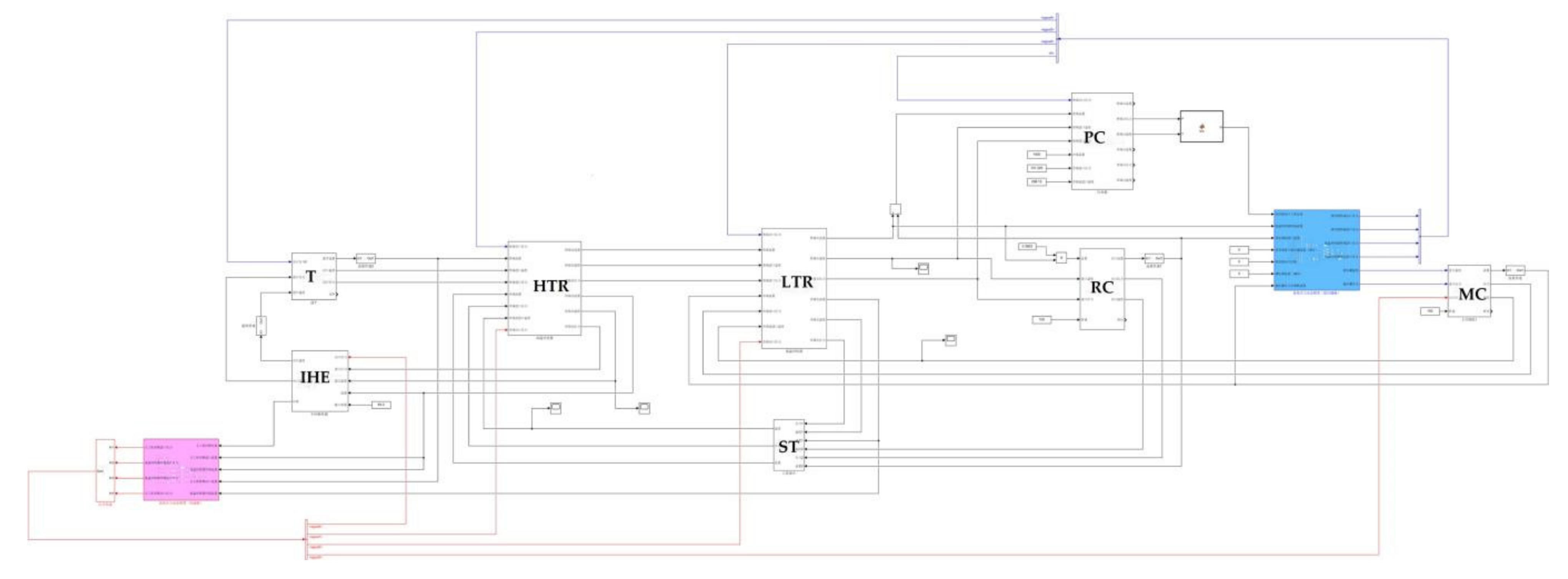
The closed-loop system model was debugged, and the initial operating parameters were calculated. With the problems of the algebraic loop and initial values solved, the SCO2 recompression power system dynamic model can be run stably. The Simulink configuration diagram is shown in Figure 7. Similar to the system configuration and modeling description in Section 2, the Simulink configuration also mainly includes the turbine (T), main compressor (MC), recompressor (RC), high-temperature and low-temperature recuperators (HTRs and LTRs), intermediate heat exchanger (IHE), pre-cooler (PC), surge tank (ST), and heater.
The heat duty was input to the system to simulate the heater in this paper at a value of 64.3 MW. The SCO2 in the IHE absorbs the heat and flows into the turbine to do work. After the heat release in the HTR and LTR, with a given split ratio (SR) at 0.3852, about 38.52% of the SCO2 flows into the RC to be compressed directly while the remaining is cooled in the PC and compressed in the MC. Then, the two streams converge at the outlet of the high-pressure side of LTR and continually flow into the HTR and IHE. Thus, an integral process is completed. The recompression model was verified under design condition. The input parameters of the design condition are shown in Table 5, and the model results and error analysis are shown in Table 6.
As shown in Table 6, the node number corresponds to the note number in Figure 1 in Section 2. Specifically, node 1 and node 2 are the turbine inlet and outlet, and node 3, node 4′, and node 5–6 refer to the flow process from the LTR inlet passing through PC to the MC outlet. The split SCO2 to the RC outlet is noted by node 4′′ and node 5′′. The two streams concentrate in the HTR inlet noted as node 8 and then flow into IHE at node 9. It can be seen from the table that the maximum error appears on the HTR inlet temperature at a value of 0.56% with a temperature difference of 2.2 °C. It is easy to note that the MC inlet temperature is kept at 304.4 °C, which is a benefit of the control of the ST. The temperature of the IHE inlet and the turbine is lower by about 1 °C, while the SCO2 temperature from the inlet of LTR to the inlet of the HTR high-pressure side is generally higher than the design value. In the preliminary analysis, the split ratio may contribute to the error and the strong coupling of the closed-loop system would also amplify the errors of the heat transfer coefficient and physical property. However, the maximum error is only 0.56%, showing that the calculation results of this model can be considered reliable.

4.3. Experiment Verification Plan

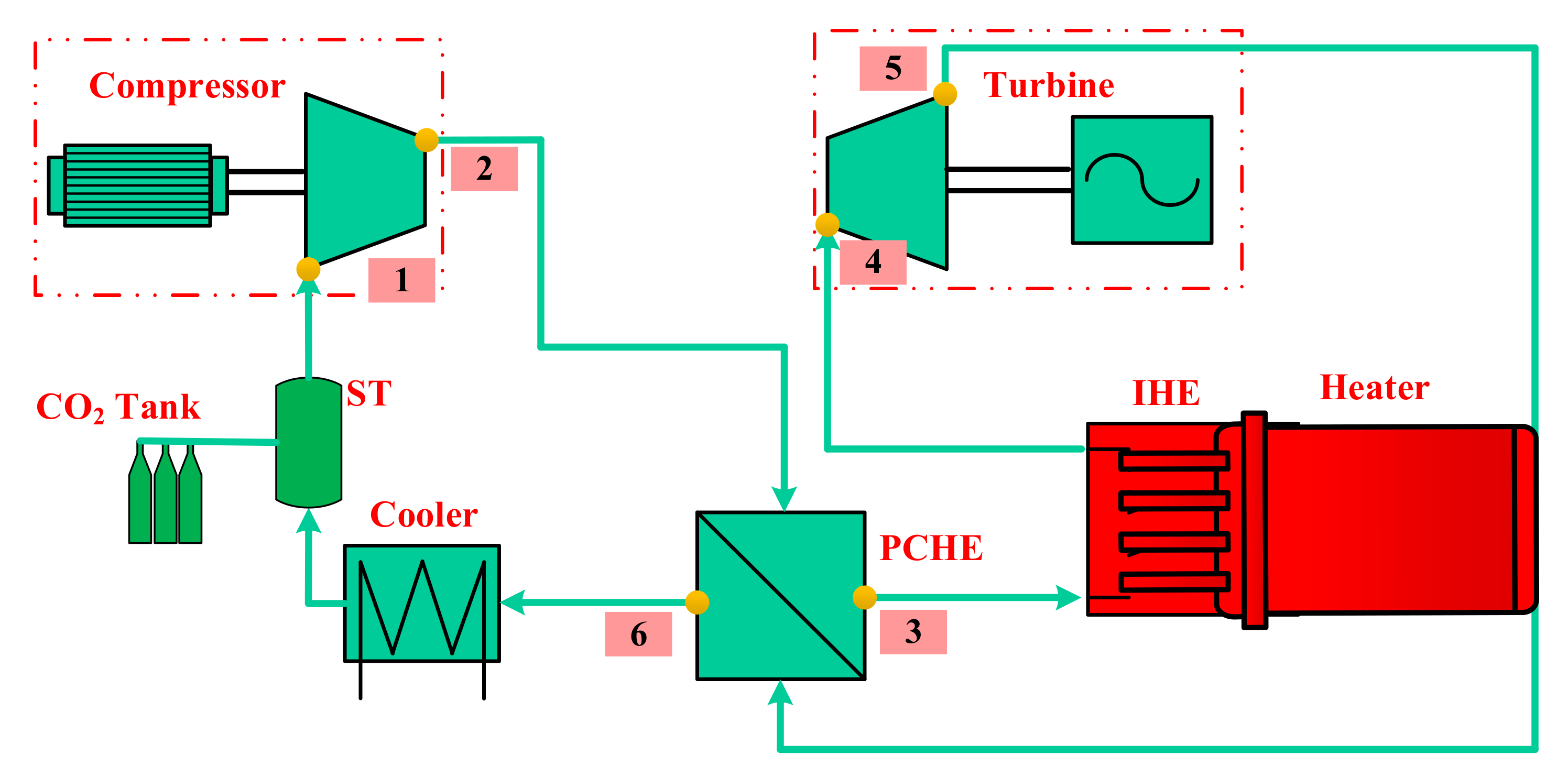
Considering the study of the CO2 Brayton circle is not mature enough, the detailed experimental data of a real power plant are very hard to obtain to support the experiment verification. Actually, our laboratory is preparing to carry out an experiment on the supercritical carbon dioxide system. The experimental loop is based on a simple regenerative cycle, and the schematic diagram is shown in Figure 8. The experiment loop includes a turbine, compressor, printed circuit heat exchanger (PCHE), intermediate heat exchanger (IHE), cooler, surge tank (ST), and heater. The design output power scale of the cycle is 1 MW and the circle efficiency is as large as 20%. The designed maximum temperature is 500 °C at the outlet of IHE, and the maximum pressure is 20 MW at the compressor outlet. At present, the experiment has entered the equipment manufacture stage, and the experiment will be carried out within one year. At this time, we will validate the developed equipment models and circle system based on the experimental results. In fact, the system model we developed will also serve the calculation of the experiment. Then, we will first validate the steady state operation system. Additionally, a series of transient-condition verification will also be carried out, including the working load increase and decrease process. Especially, the working state at a very low power state will also be performed, which will be our main focus.

5. System Dynamic Simulation of the Switching Working Condition

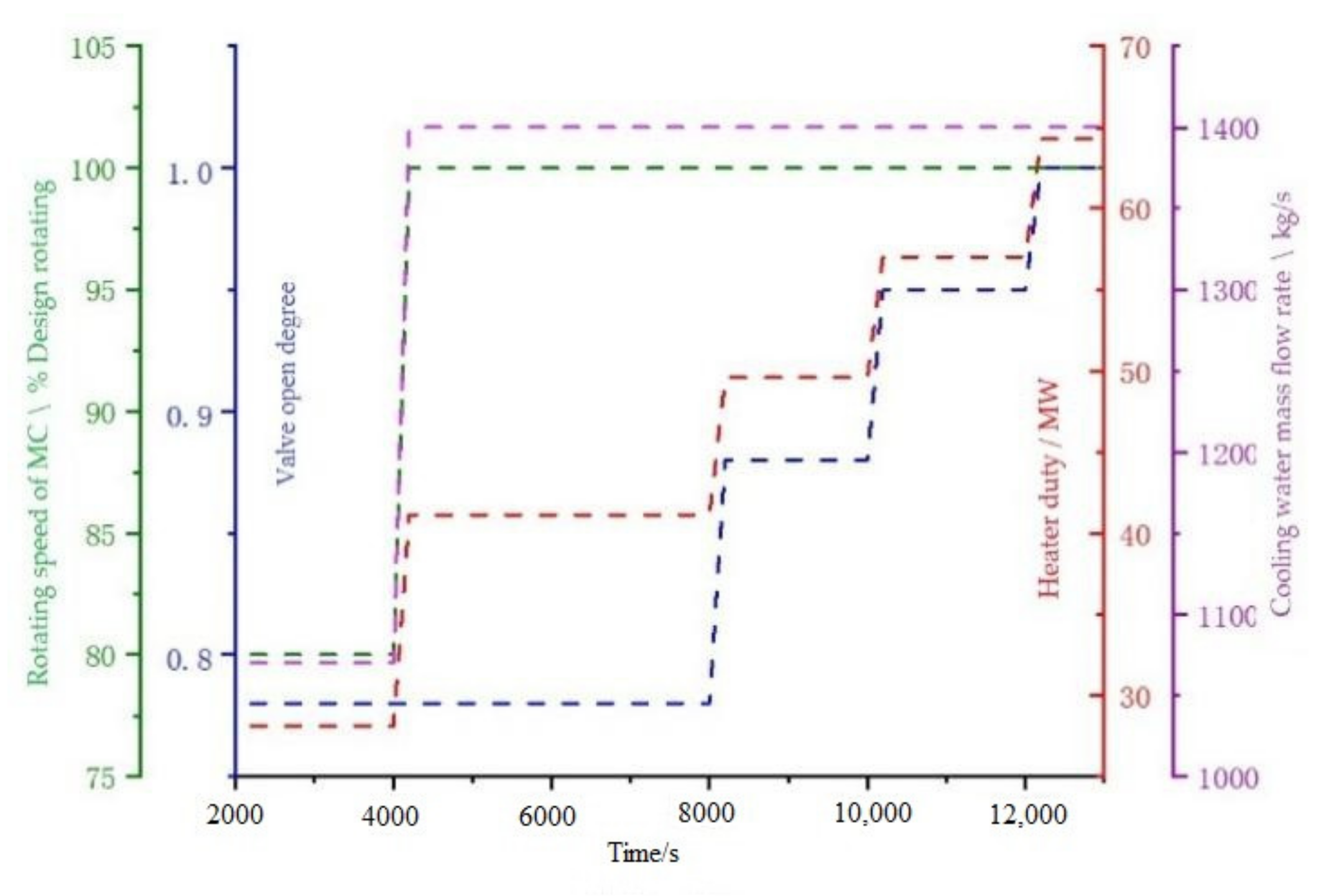
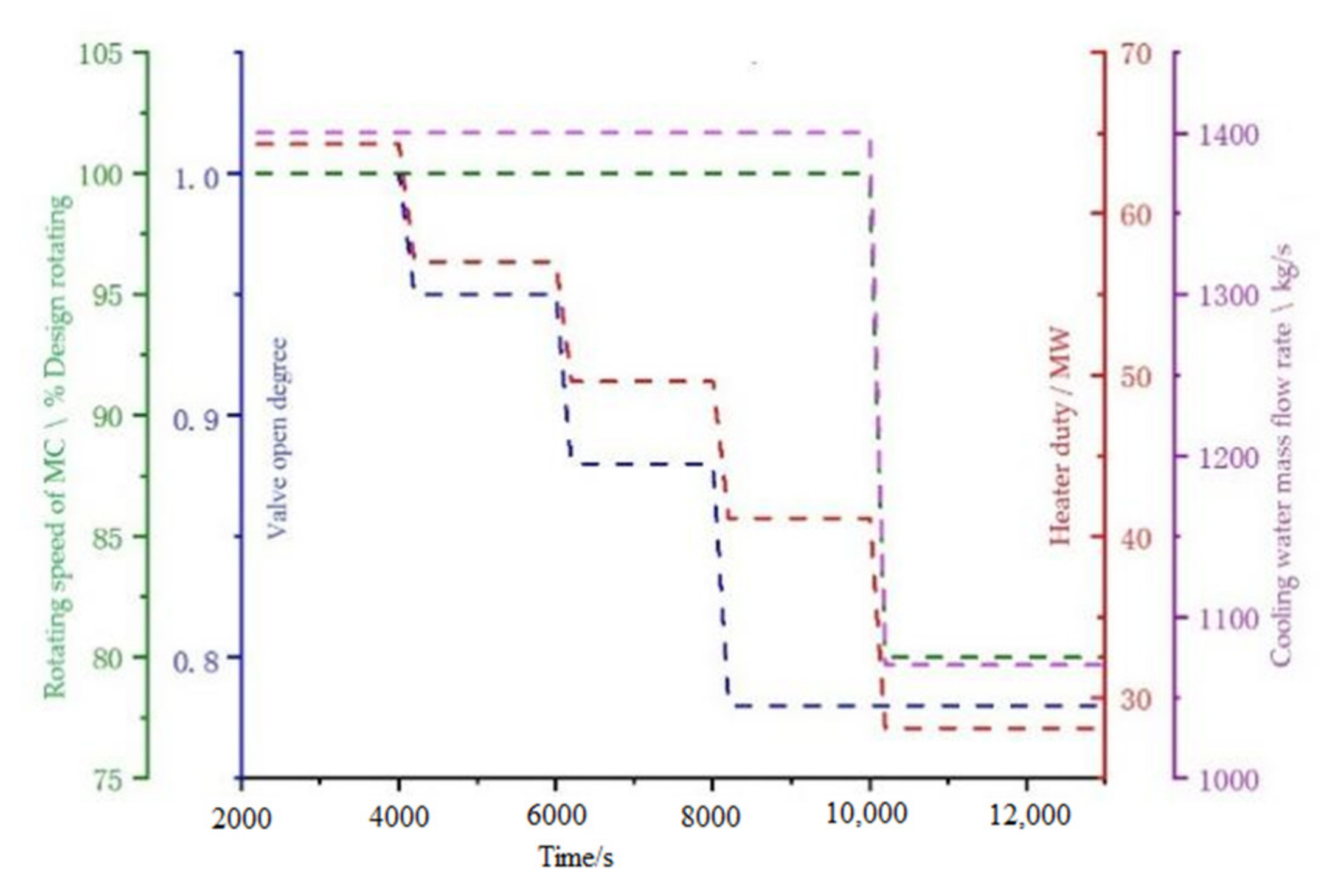
This section mainly studies the 20 MW-SCO2 system dynamic characteristics in the process of switching between various operating conditions of 100%, 80%, 60%, 40%, and 20% load. The thermal parameters of each key node of the system under non-design operating conditions were estimated according to the performance curve of the equipment. The system mass flow rate was adjusted by changing the opening of the control valve in front of the turbine, so as to achieve the purpose of a variable load. Each working load had the corresponding compressor speed, heat duty, cooling water mass flow rate, and opening degree of the control valve, as shown in Table 7.
In the simulation, the system initially operated stably under 20% operating conditions. When increasing the working load to the 40% load condition, the control valve opening degree was unchanged, and the compressor rotating speed, heat duty, and cooling water mass flow increased in a ramp manner. Then, the compressor and cooler maintained at the design condition and the control valve opening degree were increased continually to meet the load increase demand as shown in Figure 9.
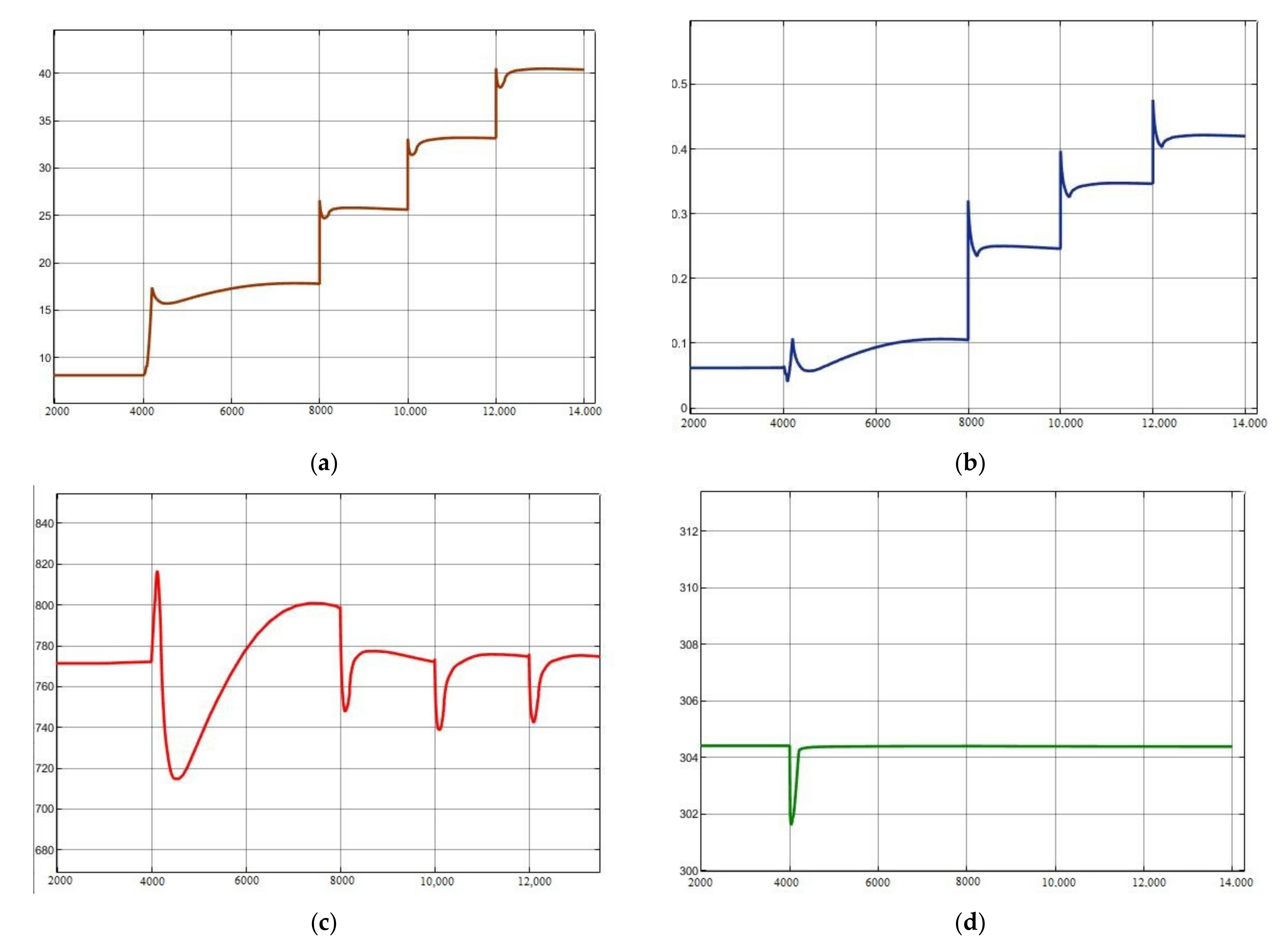
The system dynamic characteristics of the load-increasing process are shown in Figure 10. As can be seen, this operating mode can switch operating conditions by adjusting the amount of turbine distribution, while the compressor operating environment remains unchanged. This method can avoid major changes in the compressor operating environment during variable operating conditions and is beneficial to the stable operation of the system. At the same time, this method has a fast rate of changing working conditions, which can meet the demand of a fast changing load. However, this method has certain limitations for a variable load: when the load demand is below 40%, the compressor speed and cooling water mass flow experience great changes. If switching working conditions at this time, the system parameters will fluctuate greatly, and the stability time will be long. Furthermore, the compressor power consumption has to be maintained at a relatively high level, so the cycle efficiency is very low when operating at a low load.
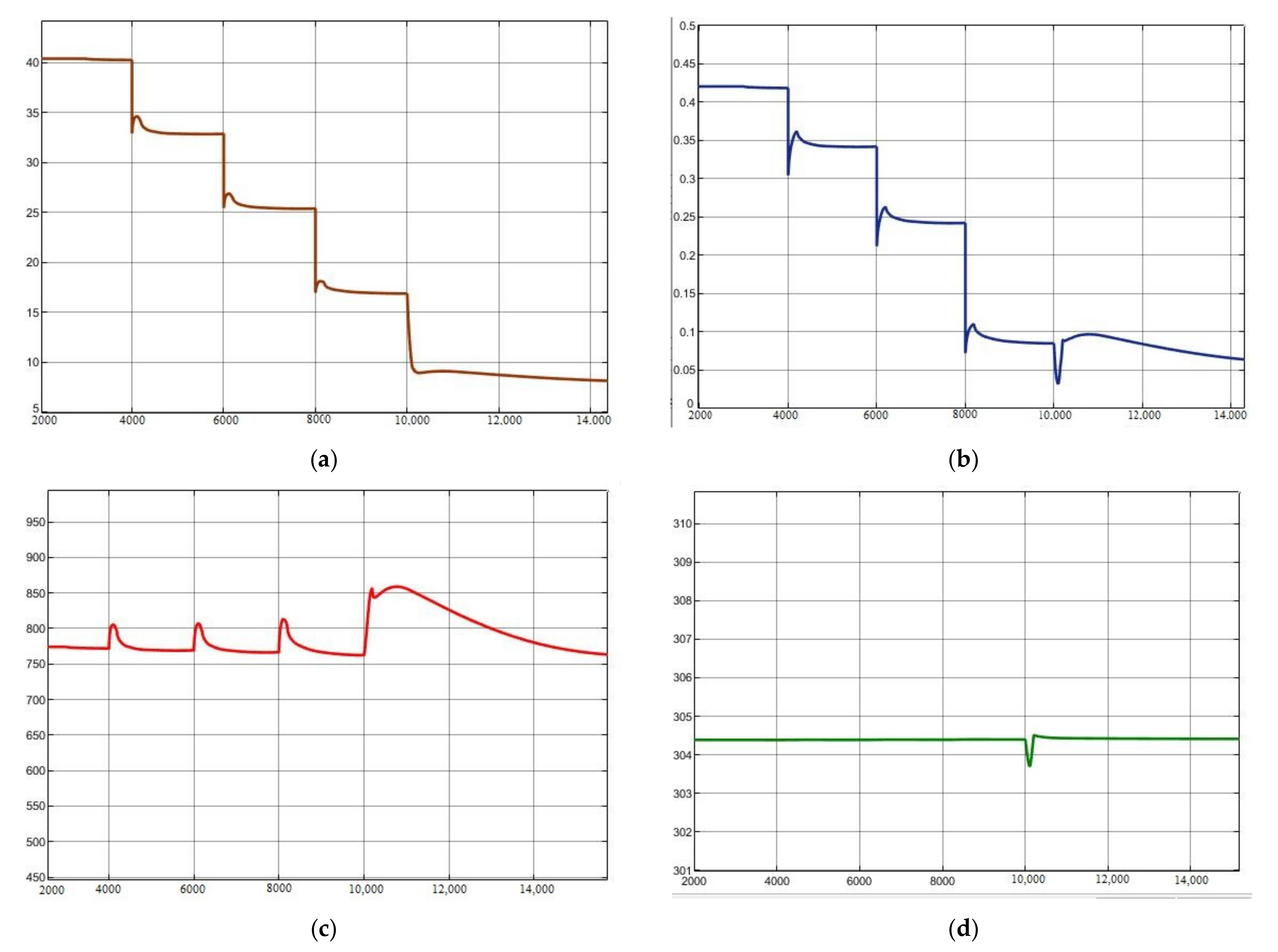
The load-decreasing process is the opposite of the load-increasing process as shown in Figure 11, and the system dynamic characteristics are shown in Figure 12. Assuming that the system initially operates stably under 100% operating conditions, the compressor and cooler operating conditions remained unchanged at first when reducing the load. The turbine power reduced with the decrease of the turbine gas flow rate and heat duty. When the load was below 40%, reducing the compressor rotating speed, and the cooling water mass flow rate at the same time caused fluctuation of the outlet temperature in the heat exchanger and displayed a longer stable time.

6. Conclusions

In this study, Simulink software was applied to develop a dynamic model of the 20 MW-SCO2 recompression cycle modularly. Corresponding component models were developed. A series of comparative calculations were carried out to verify the models. Additionally, the switching condition test of the 20 MW-SCO2 recompression cycle was conducted. The main conclusions of the study are as follows:
  • The models of a 20 MW-SCO2 recompression cycle were developed based on Simulink software, including heat exchanger models, compressor models, turbine models, and surge tank models.
  • The developed main component models were verified with the design values. The comparison results show that calculation errors are acceptable. The disturbance analysis results of the PCHE model were compared with PCHE in 1000 MW S-CO2 coal-fired power plant data to verify the dynamic simulation capacity of the model. Additionally, the prediction trends were consistent.
  • The SCO2 recompression power system was built with the developed models and the dynamic model ran stably and the maximum error was 0.56% compared to the design value.
  • The system dynamic characteristics were studied in the process of switching between various operating conditions of 100%, 80%, 60%, 40%, and 20% load. The analysis is instructive for the system operation and control.
Based on the analytical investigations, the results are very promising in that the developed model has the ability to evaluate the thermal-hydraulic characteristics of the SCO2 Brayton circulation system, but further experimental data are still needed to validate the code.

Author Contributions

Conceptualization, Z.Z.; Formal analysis, X.L.; Methodology, C.H. and M.L. Project administration, Y.L.; Software, P.S. and L.C.; Supervision, W.W.; Writing—original draft, P.S.; Writing—review and editing, C.D. All authors have read and agreed to the published version of the manuscript.

Funding

This research was funded by National Key R&D Program of China, grant number 2019YFB1901201.

Conflicts of Interest

The authors declare no conflict of interest.

Nomenclature

Abbreviations
CFPCO2 filling pump
HTRhigh temperature recuperator
IHEintermediate heat exchanger
LTRlow temperature recuperator
MCmain compressor
PCpre-cooler
PCHEprinted circuit heat exchanger
PRVpressure reducing valve
RCre-compressor
SCO2supercritical carbon dioxide
STsurge tank
TTurbine
SRsplit ratio
Symbols
c p specific heat, kJ/(kg·K)
h specific enthalpy, kJ/kg
m mass flow, kg/s
P pressure, kPa
V volume, m3
f friction loss coefficient
Ttemperature, K
γ effective loss coefficient
ρ density, kg/m3
s specific entropy, kJ/(kg·K)
η efficiency
k heat transfer coefficient, W/(m2·K)
A s Cross-sectional area, m2
Super- and Sub- scripts
hhot fluid
ccold fluid
wwall surface
ininlet
outoutlet
isisentropic

References

  1. Liu, M.; Yang, K.; Zhang, X.; Yan, J. Design and optimization of waste heat recovery system for supercritical carbon dioxide coal-fired power plant to enhance the dust collection efficiency. J. Clean. Prod. 2020, 275, 122523. [Google Scholar] [CrossRef]
  2. Ahn, Y.; Lee, J.; Kim, S.G.; Lee, J.I.; Cha, J.E.; Lee, S.W. Design consideration of supercritical CO2 power cycle integral experiment loop. Energy 2015, 86, 115–127. [Google Scholar] [CrossRef]
  3. Ishiyama, S.; Muto, Y.; Kato, Y.; Nishio, S.; Hayashi, T.; Nomoto, Y. Study of steam, helium and supercritical CO2 turbine power generations in prototype fusion power reactor. Prog. Nucl. Energy 2008, 50, 325–332. [Google Scholar] [CrossRef]
  4. Dostal, V.; Hejzlar, P.; Driscoll, M.J. The Supercritical Carbon Dioxide Power Cycle: Comparison to Other Advanced Power Cycles. Nucl. Technol. 2006, 154, 283–301. [Google Scholar] [CrossRef]
  5. Li, H.; Fan, G.; Cao, L.; Yang, Y.; Yan, X.; Dai, Y.; Zhang, G.; Wang, J. A comprehensive investigation on the design and off-design performance of supercritical carbon dioxide power system based on the small-scale lead-cooled fast reactor. J. Clean. Prod. 2020, 256, 120720. [Google Scholar] [CrossRef]
  6. Du, Y.; Yang, C.; Hu, C.; Zhang, C. Thermoeconomic analysis and inter-stage pressure ratio optimization of nuclear power supercritical CO2 multi-stage recompression. Int. J. Energy Res. 2020, 45, 2367–2382. [Google Scholar] [CrossRef]
  7. Wu, P.; Ma, Y.; Gao, C.; Liu, W.; Shan, J.; Huang, Y.; Wang, J.; Zhang, D.; Ran, X. A review of research and development of supercritical carbon dioxide Brayton cycle technology in nuclear engineering applications. Nucl. Eng. Des. 2020, 368, 110767. [Google Scholar] [CrossRef]
  8. Pan, M.; Zhu, Y.; Bian, X.; Liang, Y.; Lu, F.; Ban, Z. Theoretical analysis and comparison on supercritical CO2 based combined cycles for waste heat recovery of engine. Energy Convers. Manag. 2020, 219, 113049. [Google Scholar] [CrossRef]
  9. Liu, L.; Yang, Q.; Cui, G. Supercritical Carbon Dioxide(s-CO2) Power Cycle for Waste Heat Recovery: A Review from Thermodynamic Perspective. Processes 2020, 8, 1461. [Google Scholar] [CrossRef]
  10. Sharma, O.P.; Kaushik, S.C.; Manjunath, K. Thermodynamic analysis and optimization of a supercritical CO2 regenerative recompression Brayton cycle coupled with a marine gas turbine for shipboard waste heat recovery. Therm. Sci. Eng. Prog. 2017, 3, 62–74. [Google Scholar] [CrossRef]
  11. Ma, Y.; Morosuk, T.; Liu, M.; Liu, J. Investigation of off-design characteristics of an improved recompression supercritical carbon dioxide cycle for concentrated solar power application. Int. J. Energy Res. 2021, 45, 1818–1835. [Google Scholar] [CrossRef]
  12. Qiao, Z.; Cao, Y.; Li, P.; Wang, X.; Romero, C.E.; Pan, L. Thermoeconomic analysis of a CO2 plume geothermal and supercritical CO2 Brayton combined cycle using solar energy as auxiliary heat source. J. Clean. Prod. 2020, 256, 120374. [Google Scholar] [CrossRef]
  13. Trevisan, S.; Guédez, R.; Laumert, B. Thermo-economic optimization of an air driven supercritical CO2 Brayton power cycle for concentrating solar power plant with packed bed thermal energy storage. Sol. Energy 2020, 211, 1373–1391. [Google Scholar] [CrossRef]
  14. Liu, M.; Zhang, X.; Yang, K.; Ma, Y.; Yan, J. Optimization and comparison on supercritical CO2 power cycles integrated within coal-fired power plants considering the hot and cold end characteristics. Energy Convers. Manag. 2019, 195, 854–865. [Google Scholar] [CrossRef]
  15. Guo, J.; Li, M.; Xu, J.; Yan, J.; Ma, T. Energy, exergy and economic (3E) evaluation and conceptual design of the 1000 MW coal-fired power plants integrated with S-CO2 Brayton cycles. Energy Convers. Manag. 2020, 211, 112713. [Google Scholar] [CrossRef]
  16. Park, S.; Kim, J.; Yoon, M.; Rhim, D.; Yeom, C. Thermodynamic and economic investigation of coal-fired power plant combined with various supercritical CO2 Brayton power cycle. Appl. Therm. Eng. 2018, 130, 611–623. [Google Scholar] [CrossRef]
  17. Sarkar, J. Second law analysis of supercritical CO2 recompression Brayton cycle. Energy 2009, 34, 1172–1178. [Google Scholar] [CrossRef]
  18. Ahn, Y.; Bae, S.J.; Kim, M.; Cho, S.K.; Baik, S.; Lee, J.I.; Cha, J.E. Review of supercritical CO2 power cycle technology and current status of research and development. Nucl. Eng. Technol. 2015, 47, 647–661. [Google Scholar] [CrossRef] [Green Version]
  19. Michael, P.; Alex, K.; Edward, Z.; Timothy, H. Supercritical CO2 Power Cycle Developments and Commercialization: Why sCO2 Can Displace Steam Ste; Power-Gen India & Central Asia: New Delhi, India, 2012. [Google Scholar]
  20. Ma, Y.; Liu, M.; Yan, J.; Liu, J. Thermodynamic study of main compression intercooling effects on supercritical CO2 recompression Brayton cycle. Energy 2017, 140, 746–756. [Google Scholar] [CrossRef]
  21. Li, M.; Xu, J.; Cao, F.; Guo, J.; Tong, Z.; Zhu, H. The investigation of thermo-economic performance and conceptual design for the miniaturized lead-cooled fast reactor composing supercritical CO2 power cycle. Energy 2019, 173, 174–195. [Google Scholar] [CrossRef]
  22. Xu, J.; Sun, E.; Li, M.; Liu, H.; Zhu, B. Key issues and solution strategies for supercritical carbon dioxide coal fired power plant. Energy 2018, 157, 227–246. [Google Scholar] [CrossRef]
  23. Sun, E.; Xu, J.; Li, M.; Liu, G.; Zhu, B. Connected-top-bottom-cycle to cascade utilize flue gas heat for supercritical carbon dioxide coal fired power plant. Energy Convers. Manag. 2018, 172, 138–154. [Google Scholar] [CrossRef]
  24. Zhu, M.; Zhou, J.; Su, S.; Xu, J.; Li, A.; Chen, L.; Wang, Y.; Hu, S.; Jiang, L.; Xiang, J. Study on supercritical CO2 coal-fired boiler based on improved genetic algorithm. Energy Convers. Manag. 2020, 221, 113163. [Google Scholar] [CrossRef]
  25. Yin, J.M.; Zheng, Q.Y.; Peng, Z.R.; Zhang, X.R. Review of supercritical CO2 power cycles integrated with CSP. Int. J. Energy Res. 2019, 44, 1337–1369. [Google Scholar] [CrossRef]
  26. Liang, Y.; Chen, J.; Luo, X.; Chen, J.; Yang, Z.; Chen, Y. Simultaneous optimization of combined supercritical CO2 Brayton cycle and organic Rankine cycle integrated with concentrated solar power system. J. Clean. Prod. 2020, 266, 121927. [Google Scholar] [CrossRef]
  27. Liu, Y.; Wang, Y.; Huang, D. Supercritical CO2 Brayton cycle: A state-of-the-art review. Energy 2019, 189, 115900. [Google Scholar] [CrossRef]
  28. Dyreby, J.J. Modeling the Supercritical Carbon Dioxide Brayton Cycle with Recompression; The University of Wisconsin-Madison: Madison, WI, USA, 2014. [Google Scholar]
  29. Moisseytsev, A.; Sienicki, J.J. Simulation of S-CO2 integrated system test with anl plant dynamics code. In Proceedings of the 5th International Symposium–Supercritical CO2 Power Cycles, San Antonio, TX, USA, 28–31 March 2016. [Google Scholar]
  30. Wu, P.; Gao, C.; Shan, J. Development and verification of a transient analysis tool for reactor system using supercritical CO2 brayton cycle as power conversion system. Sci. Technol. Nucl. Install. 2018, 2018. [Google Scholar] [CrossRef] [Green Version]
  31. Deng, T.; Li, X.; Wang, Q.; Ma, T. Dynamic modelling and transient characteristics of supercritical CO2 recompression Brayton cycle. Energy 2019, 180, 292–302. [Google Scholar] [CrossRef]
  32. Chen, M.; Kim, I.H.; Sun, X.; Christensen, R.; Utgikar, V.; Sabharwall, P. Transient analysis of an FHR coupled to a helium Brayton power cycle. Prog. Nucl. Energy 2015, 83, 283–293. [Google Scholar] [CrossRef] [Green Version]
  33. Nielsen, T.R.; Rose, J.; Kragh, J. Dynamic model of counter flow air to air heat exchanger for comfort ventilation with condensation and frost formation. Appl. Therm. Eng. 2009, 29, 462–468. [Google Scholar] [CrossRef]
  34. Liu, M.; Zhang, X.; Yang, K.; Wang, B.; Yan, J. Comparison and sensitivity analysis of the efficiency enhancements of coal-fired power plants integrated with supercritical CO2 Brayton cycle and steam Rankine cycle. Energy Convers. Manag. 2019, 198, 111918. [Google Scholar] [CrossRef]
  35. Ma, C.; Wang, W.; Wu, J.; Dai, L. Analysis of unsteady flow in a supercritical carbon dioxide radial compressor stage. International Conference on Nuclear Engineering. Am. Soc. Mech. Eng. 2018, 51494, V06BT08A037. [Google Scholar]
  36. Ying, Q.; Zhuge, W.; Zhang, Y.; Ma, C.; Gou, J.; Wang, W. Vortex Patterns Investigation and Enstrophy Analysis in a Small Scale S-CO2 Axial Turbine. Energies 2021, 14, 6112. [Google Scholar] [CrossRef]
  37. Sun, J. Characteristic Simulation and Control of Supercritical Carbon Dioxide Cycle Power Generation System; Harbin Institute of Technology: Harbin, China, 2018. [Google Scholar]
  38. Ma, T.; Li, M.; Xu, J.; Cao, F. Thermodynamic analysis and performance prediction on dynamic response characteristic of PCHE in 1000 MW S-CO2 coal fired power plant. Energy 2019, 175, 123–138. [Google Scholar] [CrossRef]
Figure 1. Supercritical carbon dioxide recompression cycle power generation system.
Processes 09 01946 g001
Figure 2. The model of PCHE. (a) the structure of PCHE. (b) schematic diagram of PCHE partition calculation.
Processes 09 01946 g002
Figure 3. The performance prediction curves of the main compressor. (a) Outlet pressure prediction of MC. (b) Efficiency prediction of MC.
Processes 09 01946 g003
Figure 4. The performance prediction curves of the recompressor. (a) Outlet pressure prediction of RC. (b) Efficiency prediction of RC.
Processes 09 01946 g004
Figure 5. The performance prediction curves of the turbine. (a) Outlet pressure prediction of turbine. (b) Efficiency prediction of turbine.
Processes 09 01946 g005
Figure 6. The comparison of the temperature disturbance. (a) Temperature of the cold fluid outlet. (b) Temperature of the hot fluid outlet.
Processes 09 01946 g006
Figure 7. Simulink dynamic model diagram of the SCO2 recompression cycle.
Processes 09 01946 g007
Figure 8. Simple regenerative cycle experiment system schematic diagram.
Processes 09 01946 g008
Figure 9. Changes of the parameters in the working load increase process.
Processes 09 01946 g009
Figure 10. The system dynamic characteristics of the load-increasing process. (a) Turbine output power. (b) circle efficiency. (c) Turbine inlet temperature. (d) Compressor inlet temperature.
Processes 09 01946 g010
Figure 11. Changes of the parameters in the working load decrease process.
Processes 09 01946 g011
Figure 12. The system dynamic characteristics of the load-decreasing process. (a) Turbine output power. (b) circle efficiency. (c) Turbine inlet temperature. (d) Main Compressor inlet temperature.
Processes 09 01946 g012
Table 1. Structural parameters of PCHE.
ParametersHot SideCold Side
FluidCO2CO2
Diameter2 mm1.5 mm
Hole pitch3 mm2.5 mm
Plate thickness2 mm1.8 mm
Sheet number667667
volume1.41 m30.95 m3
PCHE size2.5 m × 2.5 m × 1.61 m
PCHE mass60,442 kg
Table 2. The outlet temperature of PCHE.
Design ValueCalculation ValueError
Hot side outlet temperature429.12 K429.4 K0.065%
Hot side outlet pressure7740 kPa7740 kPa-
Cold side outlet temperature627.15 K628.7 K0.25%
Cold side outlet pressure19,950 kPa19,950 kPa-
Table 3. Comparison of the compressor.
Main CompressorRecompressor
Design ValueModel ValueErrorDesign ValueModel ValueError
Outlet temperature\°C58.9958.351.1%153.99154.350.23%
Outlet pressure\MPa2020-19.9719.97-
Power consumption\MW5.075.050.4%8.488.470.11%
Table 4. Comparison of the turbine.
Design ValueCalculation ValueError
Outlet temperature\°C394.73394.350.1%
Outlet pressure\MPa776077330.35%
Power\MW40.6840.380.74%
Table 5. Input parameters under the design condition of the recompression cycle model.
Input ParametersValues
Rotating speed of MC\% Design rotating speed100
Rotating speed of RC\% Design rotating speed100
Spilt ratio0.3853
Cooling water temperature\K304.4
Cooling water mass flow rate\kg/s1400
Cooling water pressure\MPa0.101
Heater duty\MW64.3
Table 6. Verification of the operation results of the SCO2 recompression cycle design condition.
Node NumberTemperature\KPressure\MPa
Design ValueModelErrorsDesign ValueModelErrors
1773.90774.800.12%19.9319.920.050%
2667.88669.250.21%7.767.7580.026%
3429.12426.950.51%7.747.7380.026%
4337.14335.450.50%7.717.7080.026%
4′337.14335.450.50%7.717.7080.026%
5304.40304.40-7.77.6980.026%
6332.14331.500.19%20.019.990.050%
7421.85419.700.51%19.9719.960.050%
4′′337.14335.450.50%7.717.7080.026%
5′′427.14424.980.51%19.9719.960.050%
8424.12421.750.56%19.9519.940.050%
9627.15628.500.22%19.9519.940.050%
Efficiency41.7%41.87%0.41%---
Table 7. Corresponding parameters of each working load.
Working load20%40%60%80%100%
Control valve opening degree0.780.780.880.95100
Rotating speed of MC80100100100100
Rotating speed of RC80100100100100
Heat duty (MW)28.1141.1349.5957.0364.3
Cooling water mass flow rate (kg/s)10701400140014001400
Publisher’s Note: MDPI stays neutral with regard to jurisdictional claims in published maps and institutional affiliations.