1. Introduction
Particle image velocimetry (PIV) is a routinely used measuring method for the detailed study of flow fields in a wide variety of research fields, both in basic research [
1,
2] and practical applications [
3,
4]. Our research team has a history of using this method for characterisation of airflow movement around various types of high voltage devices [
5,
6]. A very important scientific question arises considering the presence of strong electric fields around high voltage devices and their possible interference with the PIV measuring method. The fundamental condition of proper use of PIV is that the tracer particles accurately follow the actual, studied flow, which means that the dominant force affecting the particles is the drag force of the flowing media. The common example of an external force interfering with the PIV method is the omnipresent gravitational force. Its influence is cancelled using tracer particles with density equal (or at least very similar) to the density of measured media. In our measurements, there is an analogous situation, since the strong electric field presence always generates electromagnetic forces. The main scientific question of this presented article is to evaluate the viability of using PIV in these non-standard conditions.
2. Materials and Methods
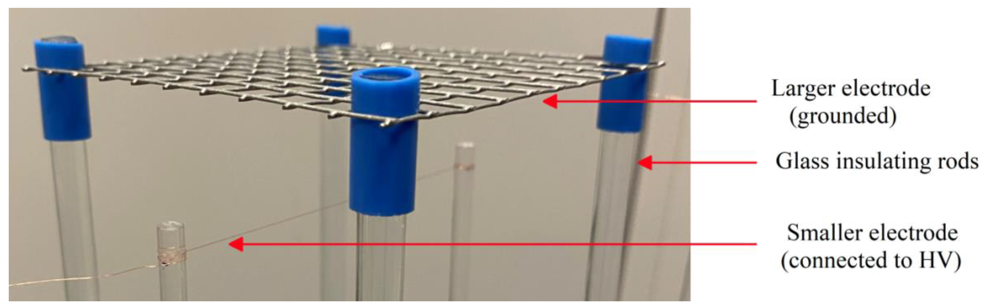
First, the system of asymmetrical electrodes was constructed. It consists of a simple planar wire mesh (wire diameter 1 mm, wire distance 10 mm and mesh size 100 × 100 mm
2), which acts as a larger grounded electrode, and of thin copper wire with a radius of 0.04 mm stretched between glass insulating rods parallel to the larger electrode in 30 mm distance; see
Figure 1. This wire acts as a smaller electrode connected to high DC voltage.
When this system of strongly asymmetrical electrodes is connected to high DC voltage, a well-defined flow of surrounding air is generated. This is caused by the ions generated in the vicinity of the smaller electrode because of the very high electric field strength around it. The ions are accelerated towards the larger grounded electrode and colliding with neutral particles of the surrounding air, thus creating airflow. The exact mechanism and its description are analysed in detail in [
7,
8].
Due to the geometry of the whole electrode system, the wire mesh can be considered from the electrical point of view as a solid conductive plane [
9]. However, from the aerodynamic viewpoint, the wire mesh causes only very small interference with the generated airflow, which can freely pass through.
The PIV measuring setup consisted of Nd:YAG green pulse laser Quantel EverGreen (with wavelength 532 nm, pulse frequency 15 Hz, length of pulse 10 ns, and energy of 25 mJ) and a high-speed digital camera HiSense (resolution 2260 × 2160, 12 bits/pixel, maximal capture rate 50 frames/s), with Nikkor 60 mm f/2.8 D AF Microlens connected through a measurement card to a PC with Dantec Dynamics Studio software.
PIV images were processed as follows: masking, cross-corelation, moving average filter, and vector statistics.
The system of asymmetrical electrodes was placed into an insulating glass box to protect the surrounding sensitive electronic devices from overvoltage and also to shield the measuring space from any disturbing airflow. The dimensions of the box (400 × 400 × 400 mm) were large enough not to restrict the generated airflow; see
Figure 2. Olive oil droplets with an average size of 10 µm were used as tracer particles, which were generated using an atomizer and seeded into the box.
Due to the presence of a strong electric field, it was necessary to keep the digital camera in a grounded Faraday cage and to keep a safe distance between sensitive components and the experiment.
Before the PIV measurement, the velocity of the generated airflow was measured using the constant temperature anemometric (CTA) probe TESTO 425. The probe was placed 10 mm above the center of the grounded wire mesh electrode. This procedure was used to measure the maximum expected velocity of the airflow at the given voltage.
2.1. Analysis of Forces
The most important force present in our experiment had to be the aerodynamic drag force because it is the basis of the PIV method functioning. The measure of the tracer particles’ fidelity to the measured flow is described by the dimensionless Stokes number Stk.
where
ρP is tracer particle density,
R represents its radius,
v is the flow velocity,
ηG is the dynamic viscosity of the flowing medium and
a is the characteristic dimension of the obstacles. In our experiment, the Stokes number Stk was expected to be in the order of 10
−4. This value is much lower than one, and therefore, the particles would follow the flow closely.
Since the velocity of tracer particles injection is orders of magnitude lower than the velocity of measured flow, their initial velocity can be considered zero. Aerodynamic drag force accelerates the tracer particle, with acceleration in the order of 105–106 m·s−2; therefore, we could consider an immediate response of the particle to the drag force. Thus, the Basset–Boussinesq–Oseen equation did not have to be used, because the problem could be described sufficiently by simple aerodynamic drag force.
As the principle behind the examined phenomenon is the motion of charged particles, we also had to consider the electromagnetic forces.
2.1.1. Aerodynamic Drag
If we consider the motion of spherical olive oil particles being caused solely by their interaction with the airflow, then the force
FD affecting the particles is described by the following drag equation:
where
C is the dimensionless drag coefficient of the particle,
S is its cross-sectional area,
ρ is the density of the surrounding fluid, and
v is the velocity of the particle relative to the fluid. In our experiment, we considered the particles as perfect spheres (
C = 0.47) with an average diameter of 10 µm, and the surrounding medium was the air with a density of 1.29 kg.m
−3. In preliminary test measurements with the constant temperature anemometric (CTA) probe TESTO 425, close to the grounded wire mesh (with a voltage of 14 kV), the results indicated an oriented airflow with the velocity ca. 1.4 ± 0.1 m·s
−1. For these values, we obtained the following drag force:
N.
The authors are aware that in real conditions, the oil particles are not perfect spheres and that the drag coefficient
C strongly depends on the exact characteristics of the flow (Reynolds number). However, the value of the drag coefficient will be even in the extreme cases only in the range of 0.1–1.6 [
10]. This means that the resulting drag force
FD can only be in the order of 10
−11 N or 10
−10 N.
2.1.2. Coulomb Forces
Usually, the oil particles are considered electrically neutral and thus unaffected by Coulomb forces. However, in our case, in the vicinity of the high voltage electrode, there is a large number of positive ions and electrons, and therefore, we cannot dismiss the possibility of the oil particles becoming charged by accepting one or more ions or electrons. If the neutral oil particle accepts one or more electrons, it becomes negatively charged and thus is attracted towards the positively charged high voltage electrode. However, the electrons are available only in a very small volume around this electrode [
11]; therefore, we did not have to consider them. On the other hand, for the neutral oil particles to become positively charged, they have to meet positive ions, which are available in the whole space between the electrodes. However, due to the extremely low probability of this effect happening at all in our conditions, even the positively charged oil particles are rarely generated.
Nevertheless, if the Coulomb forces affect the oil particles, it will cause a visible discontinuity of measured velocity under and above the grounded wire mesh electrode.
2.1.3. Dielectrophoretic Force
As the measured system of electrodes is highly asymmetrical, the generated electric field has a very strong gradient. Oil particles are considered electrically neutral; thus, another phenomenon which had to be considered is dielectrophoresis. Dielectrophoretic force
FDEF affecting a spherical electroneutral particle, with radius
R and relative permittivity
εp, can be described by the following formula [
12]:
where
εm is the relative permittivity of the medium surrounding the particle,
ε0 is the permittivity of vacuum, and
is the electric field strength. The force acts in the direction of the electric field gradient, which, in our case, was from the grounded wire mesh electrode towards the high voltage electrode. This, in essence, means that dielectrophoretic force acts against the airflow generated by the motion of ions.
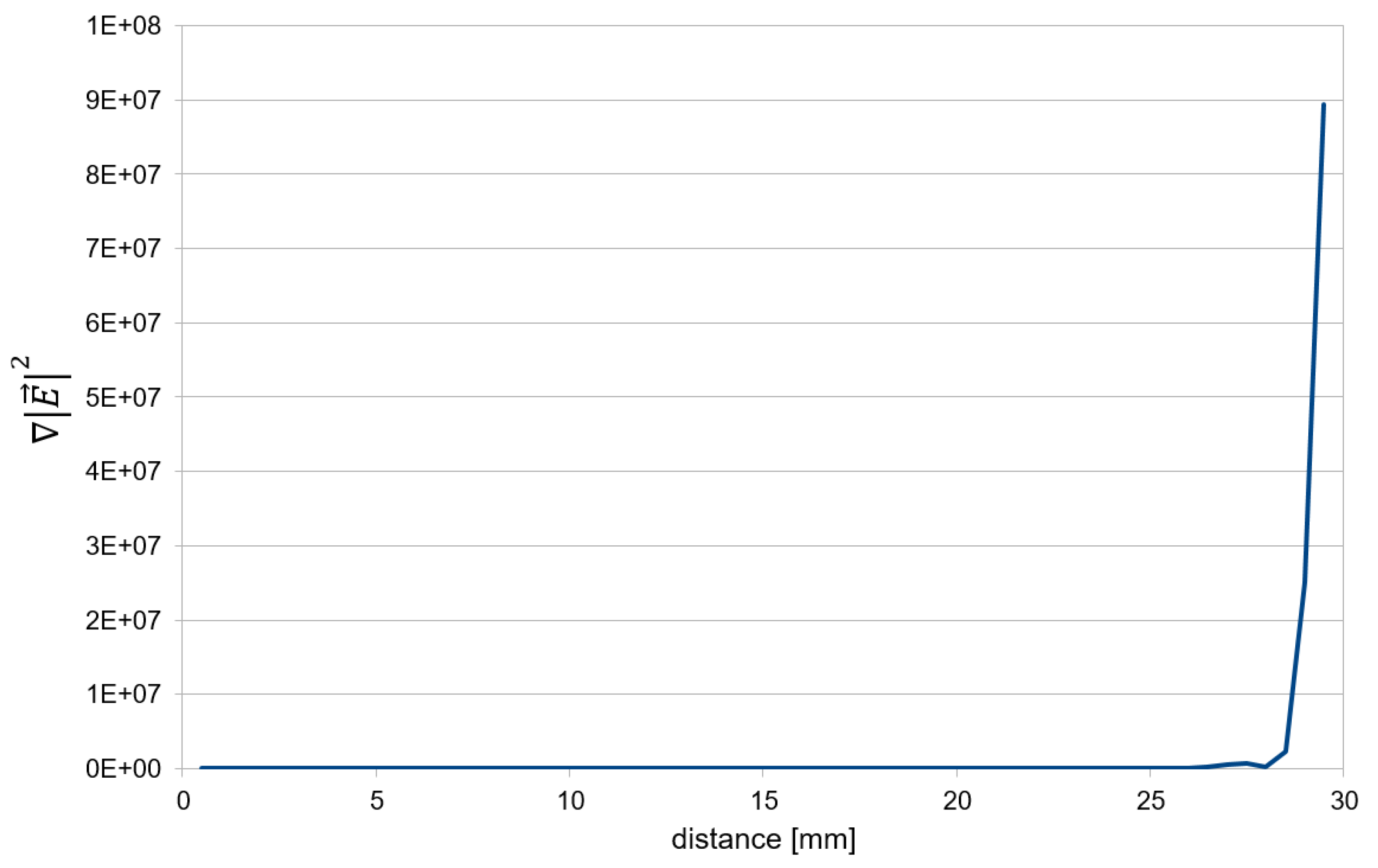
In
Figure 3, the results from a numerical simulation of the gradient of the absolute value of electrical field strength are shown, squared in relation to the distance from grounded wire mesh electrode along the shortest path between the electrodes for our geometry (distance between electrodes 30 mm) and obtained using the ANSYS FEM software. It is obvious that the values of
in the vicinity of the high-voltage electrode are extreme, heading towards mathematical singularity on the surface of the high-voltage wire electrode, which is non-physical because of the limited dielectric strength of air. Still, the physically real value of
may be seen around 1 mm from the wire electrode, which is in the order of 10
8. The area closer to the electrode was in our experiment insignificant because we examined the macroscopic character of the airflow between the electrodes. Therefore, the maximum value of dielectrophoretic force
FDEF was considered in the order of 10
−19 N.
2.1.4. Magnetic Forces
Due to the electrical current flowing through the whole circuit (in the range of tens of microamperes), the last electromagnetic force which had to be considered is magnetic force. Magnetic force
FM affecting a particle with charge
Q in motion is described by the following formula:
where
v is the velocity of the charged particle, and
B is the magnetic induction.
In the simplest case, we can consider the trajectory of charged particles as a conductive path (wire) and thus describe the magnetic induction around this path as
where
µ0 is the permeability of the vacuum,
d is the distance from the path, and
I is the current caused by the charged particles travelling between the electrodes.
By using Formulas (4) and (5), we could approximate the maximal value of magnetic force FM in our experiment in the order of 10−22 N. Additionally, the direction of the magnetic force is perpendicular to the motion of the charged particles, and therefore, the only effect on the flow this force might have is a slight rotational effect.
3. Results
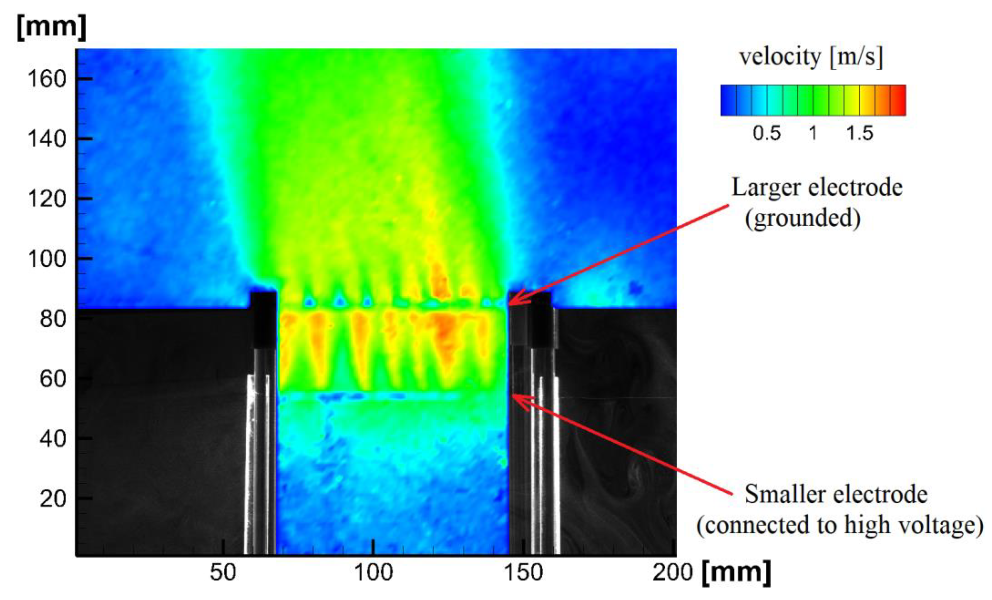
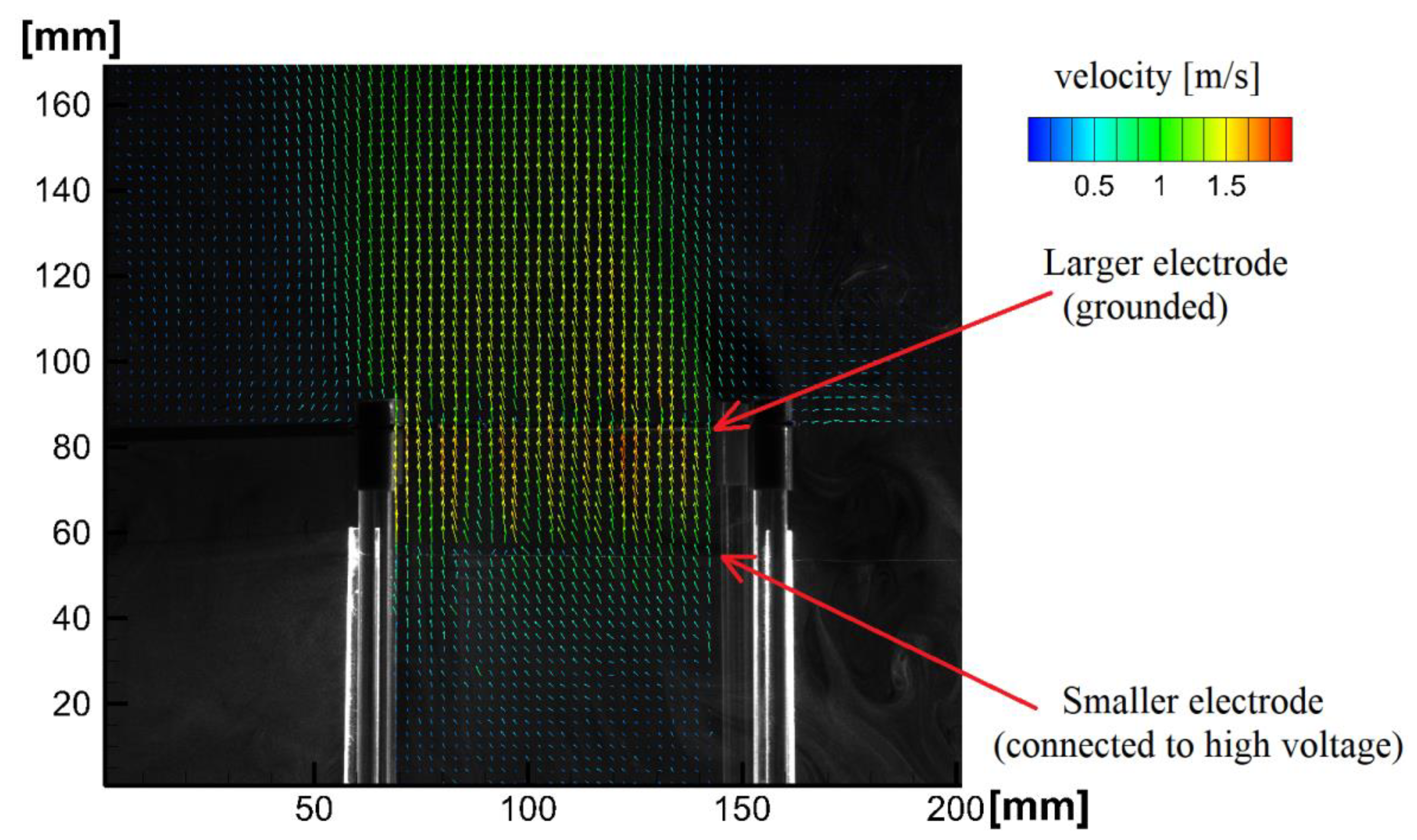
In our experimental setup, the system of asymmetrical electrodes was connected to the voltage of 14 kV, and the generated airflow was examined using the PIV method. The results can be seen in
Figure 4 and
Figure 5.
From
Figure 4, we can infer that the velocity above the grounded wire mesh electrode is around the value 1.4 m·s
−1. This corresponds with the value measured by the CTA probe (TESTO 425). It is also observed that there is no significant discontinuity in the velocity values above and below the grounded larger electrode.
In
Figure 5, it is observed that the direction of the measured airflow is as expected, from the smaller electrode to the larger electrode. The direction does not change after the airflow passes through the grounded larger electrode.
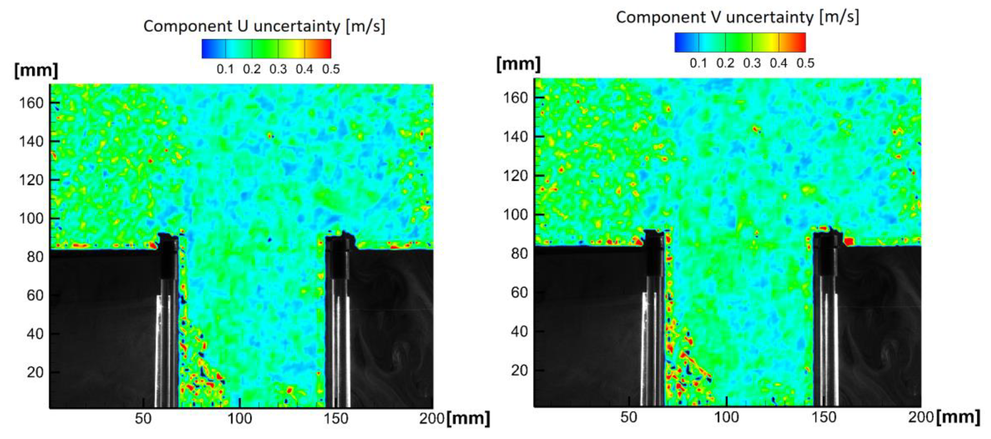
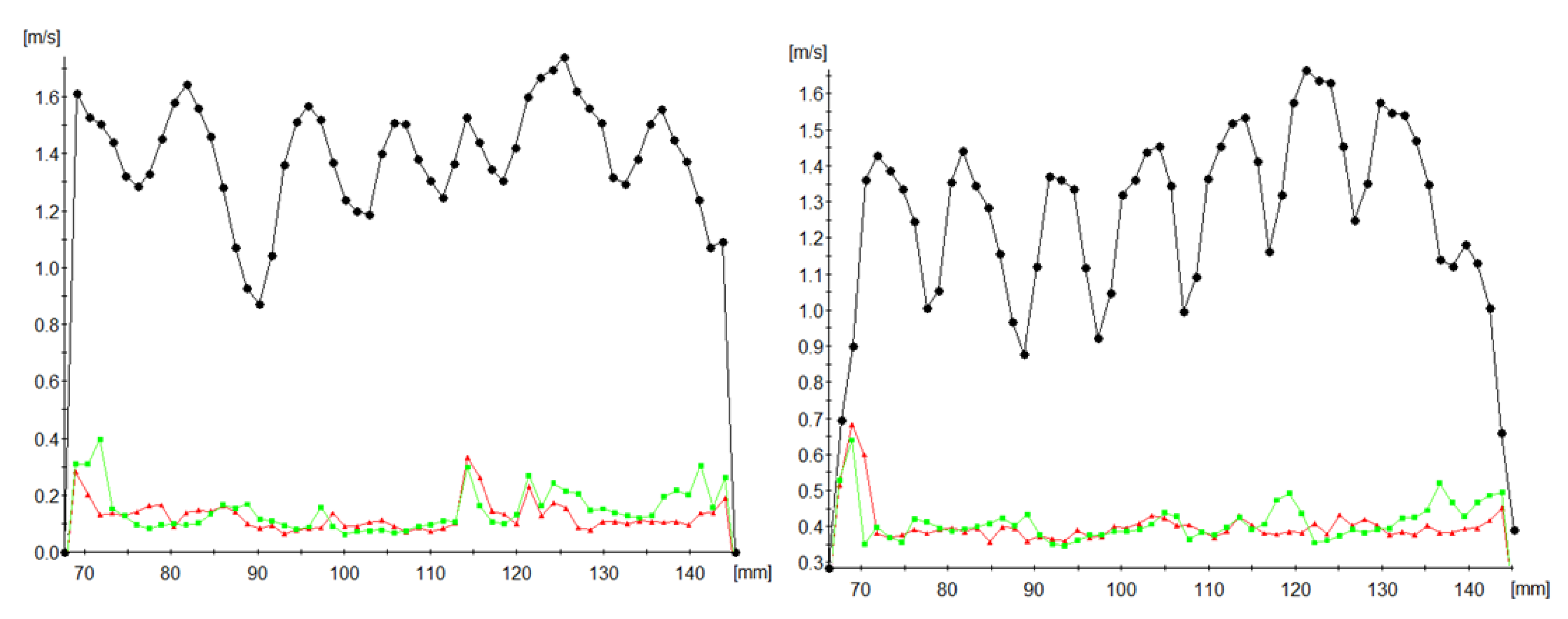
It is also necessary to mention the uncertainty of the PIV measurements.
Figure 6 presents the uncertainty maps for components
U and
V of the velocity vector
Figure 7 shows the magnitude of the velocity v does not significantly change while the generated airflow passes through the grounded wire mesh electrode. This also shows a good agreement with the independent CTA measurement.
Both
Figure 6 and
Figure 7 also prove that the PIV measurement uncertainty cannot invalidate the conclusions made in the analysis of forces (2.1).
4. Discussion
In the Introduction Section, the authors stated the question of whether the particles used for PIV measurements can be affected by the strong electric field present in the system of asymmetrical electrodes connected to high voltage. The authors analysed the relevant forces which can occur in these non-standard conditions and might influence the motion of the particles and thus the validity of the whole PIV measurement. Theoretical analysis showed that since the drag force caused by the measured airflow is at least 8 orders of magnitude higher than all the other forces, the expected results are that the PIV particles will accurately follow the measured airflow, unaffected by any electromagnetic forces.
During the experimental measurements, it was shown that the airflow velocity measured using the CTA probe and PIV measured values are in very good agreement. This fact proves that Coulomb forces have negligible effect. A second argument for this is that there is no visible discontinuity in the velocity values above and below the grounded larger electrode. If the Coulomb forces had affected the PIV particles in any significant way, these particles would have had much greater velocity than the measured airflow. Additionally, there would be a visible discontinuity in the velocity values above and below the grounded larger electrode, since charged PIV particles would have been discharged on the grounded wire mesh electrode.
Magnetic forces can be omitted because there is no visible vorticity of the measured flow field in a way that magnetic forces could cause. This was expected due to the extreme difference in orders of magnitude of drag and magnetic forces.
The influence of the last examined phenomenon, dielectrophoresis, can also be omitted, due to the difference in orders of magnitude of drag and dielectrophoretic forces. The direction of this force is exactly opposite to the direction of the flow observed during PIV measurements, and there is also an exact agreement between PIV-measured and CTA-measured velocity values.
The experimental and theoretical results clearly show the viability of the PIV measurement method even in these very specific conditions.
Author Contributions
Conceptualization, M.M. and J.P.; methodology, P.S.; data acquisition M.M., J.P. and P.S.; formal analysis, J.P.; simulation and data analysis, J.N. and P.S.; writing—original draft preparation, J.P. and M.M.; supervision, P.P.; project administration, J.N.; funding acquisition, P.P and J.P.; technical support, F.S. All authors have read and agreed to the published version of the manuscript.
Funding
This research was funded by the Technical University of Liberec, Grant Number PURE-2020-6009.
Data Availability Statement
The data presented in this study are available on request from the corresponding author. The data are not publicly available.
Conflicts of Interest
The authors declare no conflict of interest. The funders had no role in the design of the study; in the collection, analyses, or interpretation of data; in the writing of the manuscript, or in the decision to publish the results.
References
- Raffel, M.; Willert, C.E. Particle Image Velocimetry, 3rd ed.; Springer: New York, NY, USA, 2018. [Google Scholar]
- Kefayati, S.; Holdsworth, D.W. Turbulence intensity measurements using particle image velocimetry in diseased carotid artery models: Effect of stenosis severity, plaque eccentricity, and ulceration. J. Biomech. 2014, 47, 253–263. [Google Scholar] [CrossRef] [PubMed]
- Jun, B.H.; Saikrishnan, N. Micro Particle Image Velocimetry Measurements of Steady Diastolic Leakage Flow in the Hinge of a St. Jude Medical® Regent™ Mechanical Heart Valve. Ann. Biomed. Eng. 2014, 42, 526–540. [Google Scholar] [CrossRef] [PubMed] [Green Version]
- Iliescu, M.S.; Ciocan, G.D. Analysis of the Cavitating Draft Tube Vortex in a Francis Turbine Using Particle Image Velocimetry Measurements in Two-Phase Flow. J. Fluids Eng. 2008, 130, 021105. [Google Scholar] [CrossRef]
- Primas, J.; Malík, M. Calculation and measurement of a neutral air flow velocity impacting a high voltage capacitor with asymmetrical electrodes. AIP Adv. 2014, 4, 017137. [Google Scholar]
- Primas, J.; Malík, M. Particle imaging velocimetry measurement of air flow between high voltage asymmetrical electrodes. MATEC Web Conf. 2020, 328, 05007. [Google Scholar] [CrossRef]
- Tajmar, M.; Schreiber, T. Put Strong Limits on All Proposed Theories so far Assessing Electrostatic Propulsion. J. Elst. 2020, 107, 103477. [Google Scholar]
- Matsoukas, G.; Ahmed, N. Investigation of Ionic Wind as a Means of Generating Propulsive Force. Int. Rev. Aerosp. Eng. 2012, 5, 35–39. [Google Scholar]
- Feynman, R.P.; Sands, M. The Feynman Lectures on Physics, 1st ed.; FRAGMENT: Havlíčkův Brod, Czech Republic, 2001; Volume 2, pp. 135–137. [Google Scholar]
- Hoerner, S.F. Fluid-Dynamic Drag, 1st ed.; Published by the Author: Bakersfield, CA, USA, 1965. [Google Scholar]
- Primas, J.; Malík, M. Biefeld-Brown Effect-Electrohydrodynamics Phenomena on High Voltage Asymmetrical Capacitor, 1st ed.; Technical University of Liberec: Liberec, Czech Republic, 2016; pp. 56–58. [Google Scholar]
- Jones, T.B. Electromechanics of Particles, 1st ed.; Cambridge University Press: Cambridge, UK, 1995; pp. 36–40. [Google Scholar]
| Publisher’s Note: MDPI stays neutral with regard to jurisdictional claims in published maps and institutional affiliations. |
© 2021 by the authors. Licensee MDPI, Basel, Switzerland. This article is an open access article distributed under the terms and conditions of the Creative Commons Attribution (CC BY) license (https://creativecommons.org/licenses/by/4.0/).


 ,
, 