Article

Optimisation of the Geometric Parameters of Longitudinally Finned Air Cooler Tubes Operating in Mixed Convection Conditions

by
Piotr Kopeć
1 and
Beata Niezgoda-Żelasko
2,*
1
Technical Department, JUKA, 32-005 Niepołomice, Poland
2
Institute of Thermal and Process Engineering, Cracow University of Technology, 31-155 Cracow, Poland
*
Author to whom correspondence should be addressed.
Processes 2021, 9(1), 111; https://doi.org/10.3390/pr9010111
Submission received: 10 December 2020 / Revised: 2 January 2021 / Accepted: 4 January 2021 / Published: 7 January 2021
(This article belongs to the Special Issue Technical Aspects of Renewable Energy Sources (RES))

Abstract

:
The results of optimisation calculations presented in the article are related to longitudinally finned tubes of a heat pump evaporator operating under natural wind-induced flow of outdoor air conditions. The finned surface is characterised by an unusual, wavy fin shape. The article presents the methodology applied to seeking optimal geometric parameters of the finned tube in which thermal calculations were performed by modelling a mixed convection process on the finned surface using the finite volume method. In the case of maximising the heat flow with the minimum mass of the fins, the optimal solution was dominated by the minimum mass of the fins and thus geometric parameters correspond to the number of fins n = 6, fin height h = 0.065 and fin thickness s = 0.0015 m. Optimisation calculations made for maximum efficiency of the exchanger at constant mass indicated that the tube with ten fins (n = 10) with a height of h = 0.11 m and a thickness of s = 0.0018 m allowed maximum heat flow at the assumed mass of the fins in the exchanger tube model. The article proposes a simplified method of determining the optimal geometric parameters of the profile for any mass and maximum thermal efficiency.

Graphical Abstract

1. Introduction

The low price of air-to-water heat pumps makes these devices particularly popular. These heat pumps generate particularly high energy savings during the spring-summer-autumn period when the temperature of the lower heat source increases significantly. This feature of air-to-water heat pumps makes them particularly suitable for use in buildings with high hot water consumption (restaurants, hotels, hostels, hospitals, sports facilities). Thanks to the use of refrigerants such as R290, R452A, R32 (or R410A until 2020) in compressor heat pumps air-to-water heat pumps can be used at very low temperatures of the lower heat source, even −20 °C [1,2,3]. Increasing the seasonal heat efficiency index of air heat pumps is achieved, for example, by reducing energy consumption associated with the operation of the evaporator fans. Such a solution is used in air-to-water heat pumps in which the evaporator is a fanless design and operates under natural air flow conditions (free convection, mixed convection) [4]. This evaporator design additionally eliminates the energy consumption associated with automatic evaporator defrosting from the operating costs of the heat pump, as it is replaced by natural defrosting.
Evaporators of heat pumps operating in natural air flow conditions are usually made as freely arranged systems of (usually) vertical, longitudinally finned tubes (Figure 1) [2,3]. The conditions for heat exchange on the air side may be variable. The air flow can be implemented along the tubes or across the tube axis. The heat exchange can be either free convection or mixed convection. Natural air flow conditions and operation under severe frost conditions imply a high degree of development of the external surface of the evaporator (Afin/Ain ≈ 16) [5]. In the case of free convection, the thermal efficiency of the evaporator decreases significantly. In the case of mixed convection, the thermal efficiency may be at least twice as high as in the case of free convection [4].
The number of studies concerning mixed convection on external finned surfaces is limited. Studies [6,7] concern fully developed laminar flow for mixed convection on horizontal finned surfaces. Achraya and Patankar [6] analysed a case of mixed convection on the external horizontal finned surface with straight fins in a vertical arrangement. Maughan and Incropera [7], using numerical studies, analysed the effect of fin height and spacing on the intensity of the increase of heat transfer coefficients for mixed convection between parallel horizontal plates with vertical fins. Generally, as the height of the fins increased and their spacing decreased, the Nusselt number values increased. However, low values of fin spacing decreased the intensity of flow disturbances, which indicated the existence of an optimal fin spacing pitch.
Mixed convection on rectangular fins placed in a horizontal channel was the subject of experimental research by Dogan and Sivrioglu [8,9,10]. Dogan and Sivrioglu showed that when maximising heat transfer coefficients, a relationship can be found between the fin spacing, Rayleigh number and fin height [8]. Regardless of the temperature difference between the fluid and the base of the fin, the optimal value of the fin spacing pitch was 8–12 mm for Re = 250 [8] and 8–9 mm for Re = 1500 [9].
Studies on mixed convection in channels on finned vertical surfaces have been presented in studies [11,12,13]. In study [11], the influence of correlation between the pitch of fin spacing and the height of clearance in the channel on the process of heat exchange was noted. In the article [12] Al-Sarkhi and others analysed the mutual correlation of the clearance and the Rayleigh number to the Nusselt number values. Al-Sarkhi et al. [12] found significant effects of free convection on the Nusselt number values in the considered range of mixed convection.
Study [14] concerns the process of mixed convection in the laminar area in a vertical channel with fins equipped with vortex generators. The results showed an unusual effect of the flow rate on the efficiency of the fins. For small fin spacing, the efficiency of the fins increased abnormally with the flow rate. For large fin spacing, the increase in flow rate was accompanied by a decrease in efficiency of the fins.
The issues related to the evaluation of finned surfaces can be divided into a group of issues concerning single fins [15,16,17,18,19,20] or developed surfaces and heat exchangers [21,22,23,24,25,26]. Considerations concerning individual fins are focused on determining the optimal fin profile [17,18,19] and its parameters: thickness [19], height and base diameter [17]. In the cases under consideration [17,19], the assumed optimisation criterion was to minimise the mass of the fin conducting a constant heat flow or to minimize the maximum fin temperature [19]. The criteria for the evaluation of finned surfaces allowing for their comparison include, in the case of forced convection, in addition to parameters defining thermal processes, also parameters characterising flow phenomena, especially flow resistance. Often, the evaluation criterion is the so-called flow quality factor (being the quotient of the Colburn factor and the local resistance coefficient) or the quotient of the heat transfer coefficients or the transferred heat flow to the pumping power related to the front face area [27]. An exergetic criterion related to minimising the value of entropy of the fluid generated on the finned surface side is also applied [14,28].
In the case of the flow around a finned surface under natural wind-induced air flow conditions, the optimisation criterion may correspond to the criterion for heat exchange under free convection conditions, although the calculation model must take into account heat exchange under mixed convection conditions.
The lack of studies adequate to the case under consideration allows a search for conditions for the selection of optimal geometric parameters of finned surfaces in the literature referring to numerical analysis of heat exchange processes under free convection conditions on longitudinally finned surfaces [29,30]. Study [31] presented a numerical analysis of the effect of thickness, fin height and number of fins in free convection on the distribution of rate, temperature and heat flow outside the horizontal longitudinally finned cylindrical surface. The authors noted that the maximum heat flow conducted by the finned surface is obtained for a fin thickness of less than 0.01 m and a height of not more than 0.2 m. The maximum heat flow conducted by the finned surface was obtained for the number of fins between 6–12. In [32], Haldar analysed the effect of the number of fins, their length and buoyancy force on the intensity of heat transfer through a horizontal tube with longitudinally finned straight fins mounted axially symmetrically ( 0 2 h / d out 0.6 ; dout = 0.01 m; 0 n fin 18 ). Haldar [32] analysed, among other issues, the effect of the number and height of fins on the process of heat exchange, assuming a constant surface area of the fins. According to [32], for the Grashof number Gr < 103 it is advisable to use fewer, higher fins. For larger Grashof number values, a larger increase in heat transfer coefficients is achieved for a greater number of lower fins. The process of natural air convection in a cylindrical horizontal channel on the external surface of a horizontal longitudinally finned tube with six fins, was analysed in the study [33]. Analysing the results of numerical calculations, Farinas and others [33] indicated that in relation to a smooth tube, the highest fins analysed are the most effective 0.25 2 h / d out 0.75 .
The subject of the present study is the application of numerical modelling to the selection of geometric parameters of evaporator tubes presented in Figure 1a, for the cross-section of tubes presented in Figure 1b. Taking into account the shape of the fin (sinusoidally corrugated longitudinal fin mounted on the vertical tube), the direction of air flow (longitudinal or transverse) and the conditions under which the heat exchange process is carried out (mixed convection), it is difficult to find the dependencies adequate for the investigated case for calculating heat transfer coefficients in the literature [34,35,36,37,38,39,40,41,42]. Study [5] presented case relevant experimental results of local and average values of heat transfer coefficients for free and mixed convection at transverse air flow ( 0 w a 2.3 ms−1). The values of heat transfer coefficients measured by the authors were in the ranges 2–7 Wm−2 K−1 (free convection) and 4–20 Wm−2 K−1 (mixed convection). This article is a continuation of the research presented in publications [5] and [43]. Low values of heat transfer coefficients, maximisation of COP, operation at low ambient temperatures imply a large area of the external surface of the heat pump evaporator. The materials (aluminium, copper), the manufacturing technology for the external profile and the large surface area of the evaporator determine its high price. An important design issue is the proper selection of geometric parameters of the external aluminium profile ensuring maximum heat flow from the outside air. The purpose of this article is to optimize the geometric parameters (fin thickness, height, number of fins) of the longitudinally finned tube, with axially-symmetrically mounted sinusoidal fins, for two optimisation criteria. The values of the optimised objective functions were determined on the basis of CFD (Ansys) numerical modelling of the heat transfer process on the external surface of the evaporator tubes. The calculations were made for the case of mixed convection, free convection on a vertical tube and forced convection for a transverse flow around tubes. The original aspects presented in the article concern the association of specific evaporator design, mixed convection process and optimisation issue. The article proposes a simplified method of determining the optimal geometric parameters of the profile for any mass and maximum thermal efficiency. The results of the optimisation calculations can present significant utility for the construction of heat pumps where the lower heat source is external air, or waste air, and the evaporator is a fanless design.

2. Calculation Model

The subject of consideration is the process of heat exchange on the external surface of a vertical tube finned with several aluminium longitudinal fins set centrally-symmetrically around the perimeter of the tube, with a copper tube as an inner core (Figure 1). Tubes of this type are used in the construction of evaporators of heat pumps not equipped with fans. The operation of evaporators in natural conditions enables free arrangement of the evaporator tubes. Low outside air flow rates with a variable direction of inflow force significant surface development, obtained through the appropriate length and wavy shape of the fins. The loose vertical position of the tubes favours possible natural defrosting of the exchanger. The process of heat exchange on the external surface of the tubes is a combination of free convection on the vertical tube and forced convection on the transverse flow around the tubes (at low air flow rates). The free positioning of tubes with a length of L = 2 m at a distance of at least Sq = 0.2306 m allows treatment of each of them separately. The geometric parameters characterising the finned surface are number of fins (nfin), fin thickness (s) and fin height (h). Fin height h is the equivalent height of a straight fin with a surface area corresponding to the actual fin surface area:
h = A f i n / ( n · L )
For the considered fin shape between the actual fin height hfin and the equivalent height h, the relation h f i n =   0.8326 · h applies.
Experimental studies on the process of heat exchange at the transverse flow around the finned tube under mixed convection conditions were presented in detail in study [5]. The results of the research presented by Niezgoda-Żelasko and Żelasko [5] included local temperature distribution on the perimeter and along the finned tube as well as local and mean values of heat transfer coefficients.
The adopted calculations model included conservation equations describing the process of a mixed convection including the equations of momentum, energy and mass conservation [44], extended with dependencies allowing to take into account the occurrence of mass forces (free convection) or turbulent stresses (turbulent flow). Due to temperature differences between the wall and air 10 < ΔT < 40 K [5], air was treated as an incompressible ideal gas and its density was determined from the Clapeyron equation [44]. According to [44], if the Richardson number value is close to one (Ri ≈ 1), the heat transfer process should be modeled as a simultaneous free and forced convection process. If Ri < 1, the effect of free convection can be omitted from the calculation. The experimental studies were conducted for mixed convection in the range of Richardson number values of 2.1 × 10 2 Ri 7 × 10 2 [5]. However, due to the height of the tube and the specific geometry of the tube, it was assumed that this was mixed convection and the calculation took into account the effect of buoyancy forces on the heat transfer process. The equations of kinetic turbulence energy (k) and proper dissipation of kinetic turbulence energy (ω) were modelled according to the k-ω SST model [44]. The k-ω SST model was adopted because of lower overproduction of kinetic turbulence energy in cases of strong positive pressure gradients, e.g., in the areas of accumulation or tearing of the boundary layer. This allowed to better describe the flow issues in the immediate vicinity of the fins and in the space between the fins.
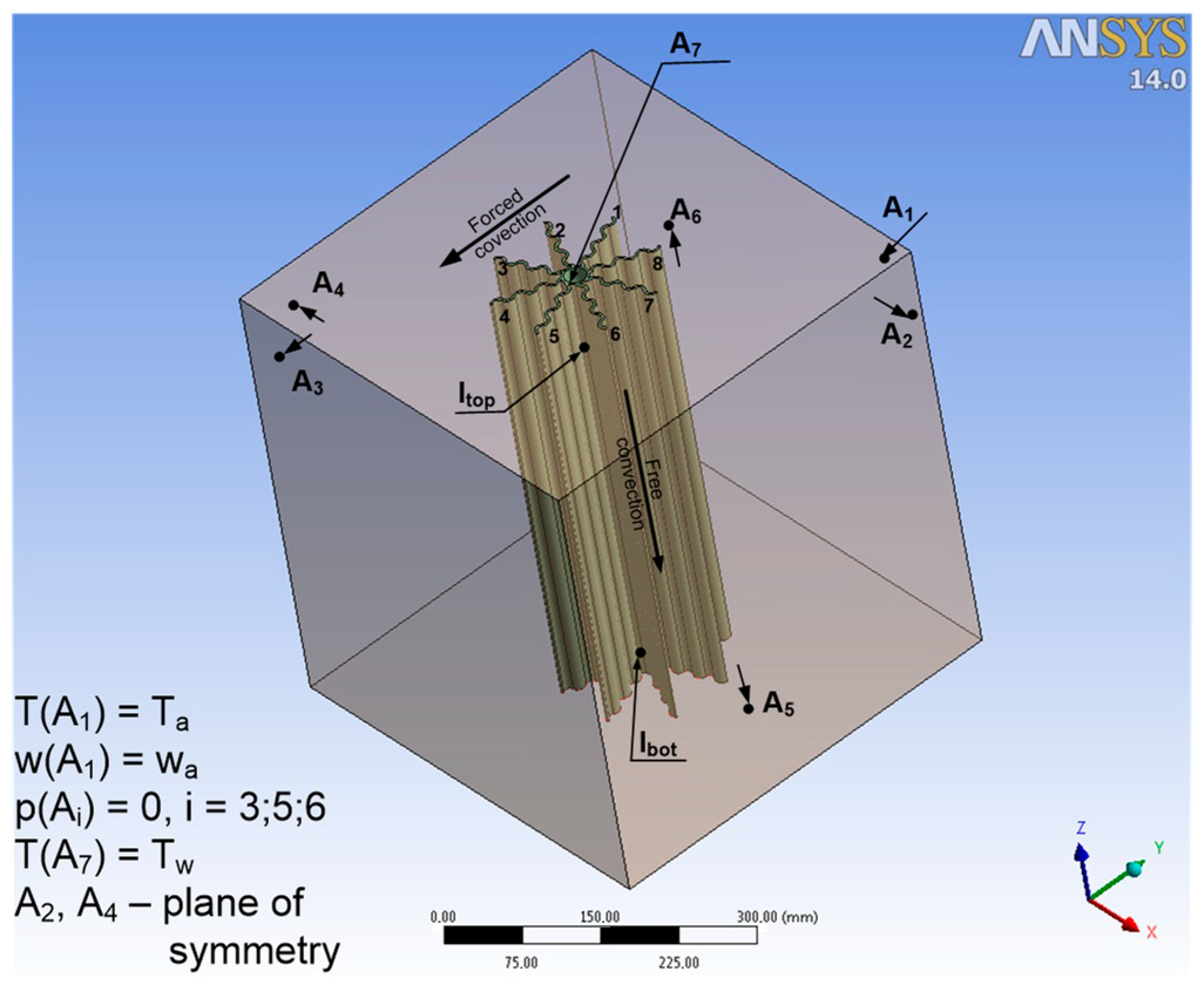
The heat transfer process between the finned tube and the outside air, including the aforementioned equations, was modelled using the finite volume method and Ansys-Fluent software. Modelling of the mixed convection process, the fin shape and the transverse direction of air flow required the model to be prepared in 3D space. A hexagonal grid of 9 × 10⁶ elements was generated for the geometric model corresponding to the actual dimensions of the finned tube. In the overlapping areas of boundary conditions and the area of air contact with the exchanger, the grid was thickened. During the calculation, the required accuracy of the calculations was obtained for the conjugate convergence criterion set at a value of 10−6. The boundary conditions adopted for the calculation are shown in Figure 2.
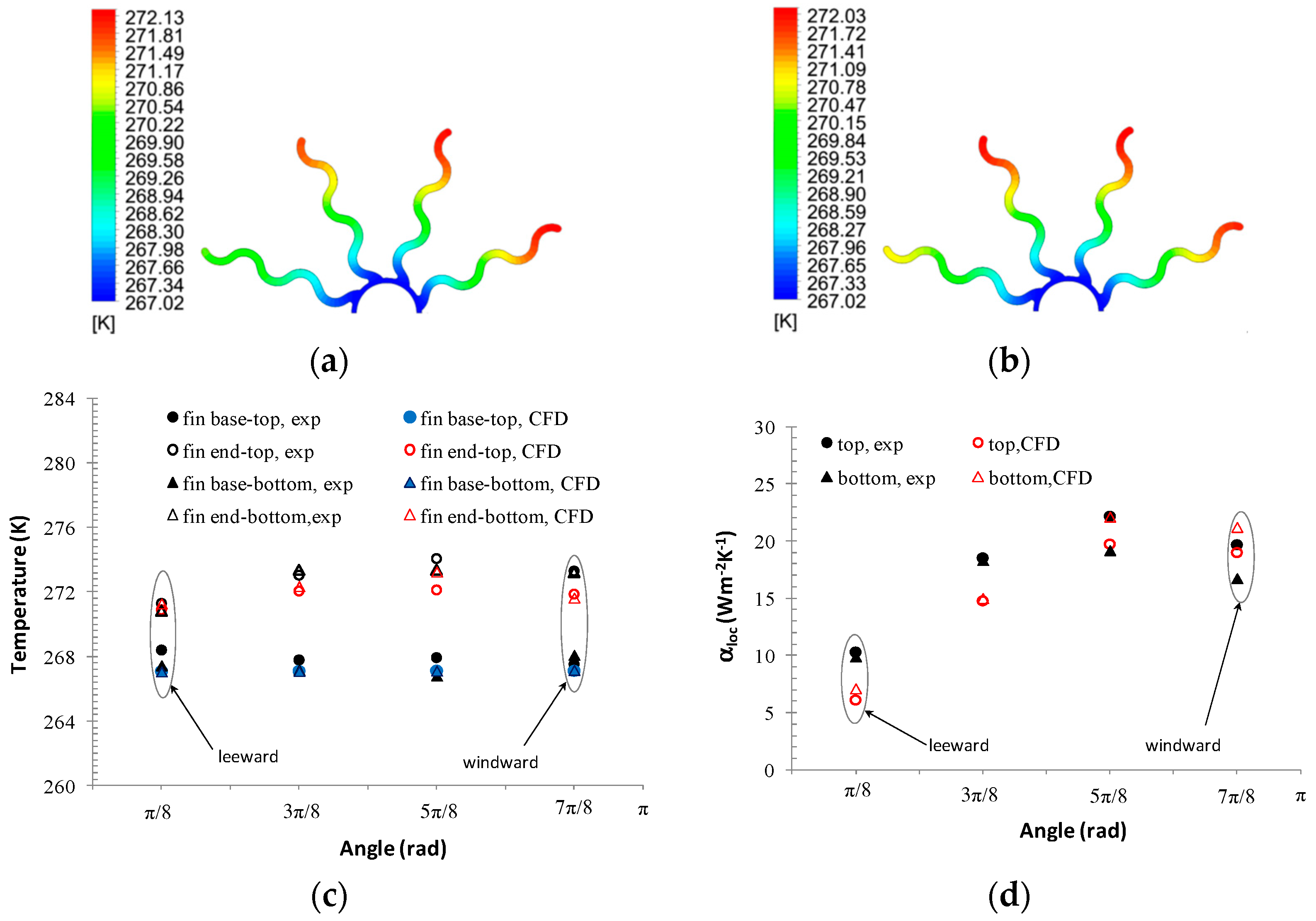
A full validation of the calculation model based on own experimental results [5] including verification of temperature distribution, local values of heat transfer coefficients and fin efficiency was presented in [43,45]. Verification of the adopted calculation model included the range of Reynolds numbers (0 < Re = w a · d o u t · ρ a / μ a < 6300, wamax = 2.3 ms−1). The calculation model adopted for mixed convection, with a k-ω SST turbulence model, is more suited to the transient flow range, which can particularly occur on the leeward side of the profile. It should not be excluded that for very large Reynolds numbers, the k-ε model may also be an adequate model of turbulence. The results of the calculations confirmed qualitative changes in temperature distribution and heat transfer coefficients on the perimeter and along the tube height. The calculated local distributions of temperature and heat transfer coefficient were compared with the experimental values measured at two tube heights lbott = 0.2 m and ltop = 1.6 m [5]. Figure 3 shows sample results of verification of the calculation model obtained for mixed convection (frontal air velocity wa = 2.3 ms−1, average temperature difference between air temperature and fin base temperature Δ T = Δ T ¯ a Δ T ¯ w a l l = 25   o C ). The results of the calculations presented in Figure 3c,d show that under the considered conditions of mixed convection, the forced convection process dominated. Similar values of heat transfer coefficients were observed in the lower and upper part of the tube. The average deviations between the calculated and measured values of temperatures, heat transfer coefficients and fin efficiency were in the following ranges: <0; 2.6%> for temperature distribution, <−11%; 23%> for local values of heat transfer coefficients and <0; 6%> for fin efficiency. The reason for the discrepancy between the experimental and simulation results may be the fact that the condensation effect on the surface of the exchanger tubes is omitted from the simulation calculations. Any conditions under which the experimental research was conducted were characterised by low relative air humidity (φ = 30–40%) and minimal frosting of the exchanger [4].
The experimentally verified calculation model was used in the presented study to determine the thermal efficiency of the heat pump evaporator tube, for various geometric parameters.

3. Optimisation of Geometric Parameters of Heat Pump Evaporator Tubes

3.1. Assumptions for Optimisation Calculations

As already mentioned, evaporators of heat pumps operating in conditions of natural, wind-induced outdoor air flow have a specific design that differs from the traditional design of finned exchangers. The process of evaporation of the refrigerant inside the exchanger tubes imposes the condition of absolute tightness of the exchanger, while maintaining the simplicity of making tight connections of tubes by soldering. Therefore, the exchanger is made of copper tubes on which an aluminium profile formed by an external tube with fins is mounted [46]. The costs of making the exchanger depend on the price of manufacturing the aluminium profile, the price of the copper tube and the price of expanding it inside the aluminium profile. The reduction of the operating costs of the heat pump in this case is related to the increase in mass (surface area), and thus the price of the heat pump evaporator. Therefore, the specific design and operating conditions of the exchanger make the optimisation issue defined for this device limited to maximising the heat transfer flow with a minimum mass or constant mass of the exchanger, while ignoring the flow resistance on the air side. Due to the practically identical operating conditions of each of the exchanger tubes, this issue can be formulated for a single tube. The optimisation variables in this case are the average thickness of the fin, its height and number of fins. Two criteria for optimising the exchanger tubes can therefore be considered:
  • − maximisation of heat flow for constant mass of the aluminium profile
G 2 ( s , h , n ) = Q ˙ ( s , h , n ) m a x
  • − with the equality constraint:
M PR ( s , h , n ) = ρ A l · n · h · s · L = c o n s t
  • − maximisation of the objective function, which is the quotient of the heat flow to the mass of the aluminium profile:
G 1 ( s , h , n ) = Q ˙ ( s , h , n ) M PR ( s , h , n ) m a x
It should be noted that due to climatic conditions, the actual operating conditions of the heat pump evaporator in the heating cycle will usually correspond to those of mixed convection. Additionally, it is obvious that under conditions of zero air flow rate or relatively small temperature differences ∆T = Ta−Tw, the results of the optimisation calculations (heat flow maximisation) for free convection will correspond to the fins with maximum surface area and fin efficiency. Therefore, the considerations concerning the indication of recommended geometric parameters of the fins were carried out for mixed convection conditions. Optimisation calculations were performed for typical operating and design conditions for the evaporator, omitting extreme operating conditions in free convection or frosted conditions. The methodology of solving the optimisation issue was based on the parameterisation of the thermal efficiency function (as a function of geometric parameters) resulting from CFD calculations of the heat and momentum exchange process on the external surface of the tubes of the considered heat exchanger. The search area for optimal solutions included ranges of parameter variability: number of fins (n), height (h) and fin thickness (s) defined by Equations (5)–(7)
6 n 12
0.065   m h 0.167   m ,
0.001   m s 0.004   m   ( 0.0049   m   for   function   G 1 ) .
Due to the full geometric symmetry of the exchanger, only even numbers of fins were considered. Optimisation calculations are usually associated with repeated calculations of the value of the objective function for arguments determined according to a certain procedure resulting from the adopted optimisation method. In this case, due to the use of CFD modelling to determine the value of the objective function, it was decided to draw up an extensive dependency base, Equation (8):
Q ˙ ( s , h )       w h e r e       n =   6 ,   8 ,   10 ,   12
The calculations were made for constant boundary conditions (Figure 2):
  • − inlet flow rate condition, wa = 2.3 ms−1,
  • − free flow condition at the outlet, p = 0 Pa
  • − outside air temperature, Ta = 275.15 K,
  • − temperature on the inner surface of the exchanger tube, Tw = 247.15 K.

3.2. Results of Optimisation Calculations

3.2.1. Maximisation of the Heat Flow at Minimum Mass

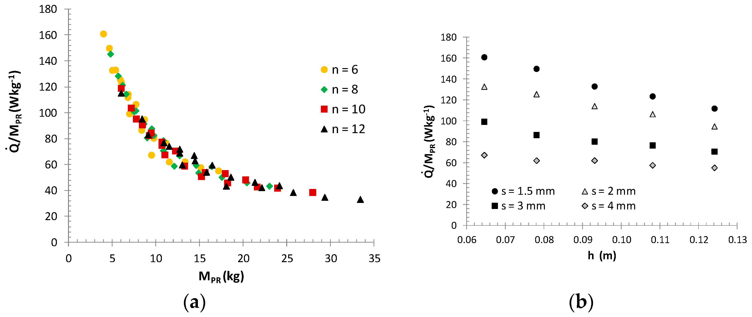
Maximising the thermal efficiency with the minimum mass of the aluminium profile can be included in the search for the maximum of the objective function defined by Equation (4). The influence of the mass of the aluminium profile of the exchanger on the value of the objective function (4) is presented in Figure 4a.
Figure 4a shows the dominant influence of the exchanger mass on the value of the objective function under consideration and that the highest values of the G2 function are obtained for the case of n = 6 fins mounted on the tube. Figure 4b shows the effect of the thickness and height of the fin on the values analysed for the objective function G 2 = Q ˙ / M P R . In this case, it should be noted that the minimum number of short and thin fins allows for a minimum mass and at the same time promotes the formation of flow disturbances at the entire height of the fins, improving the process of heat exchange on the air side. Thus, within the considered range of variability of the arguments (Equation (4)), the maximum value of the objective function G2max = 160 Wkg−1 was reached at the boundaries of the range for: n = 6, h = 0.065 m, s = 0.0015 m. For these geometric parameters, the efficiency of a single exchanger tube was Q ˙ =   648 W, with the mass of the fins MPR = 4.02 kg.

3.2.2. Maximising Heat Flow at Constant Mass MPR-M

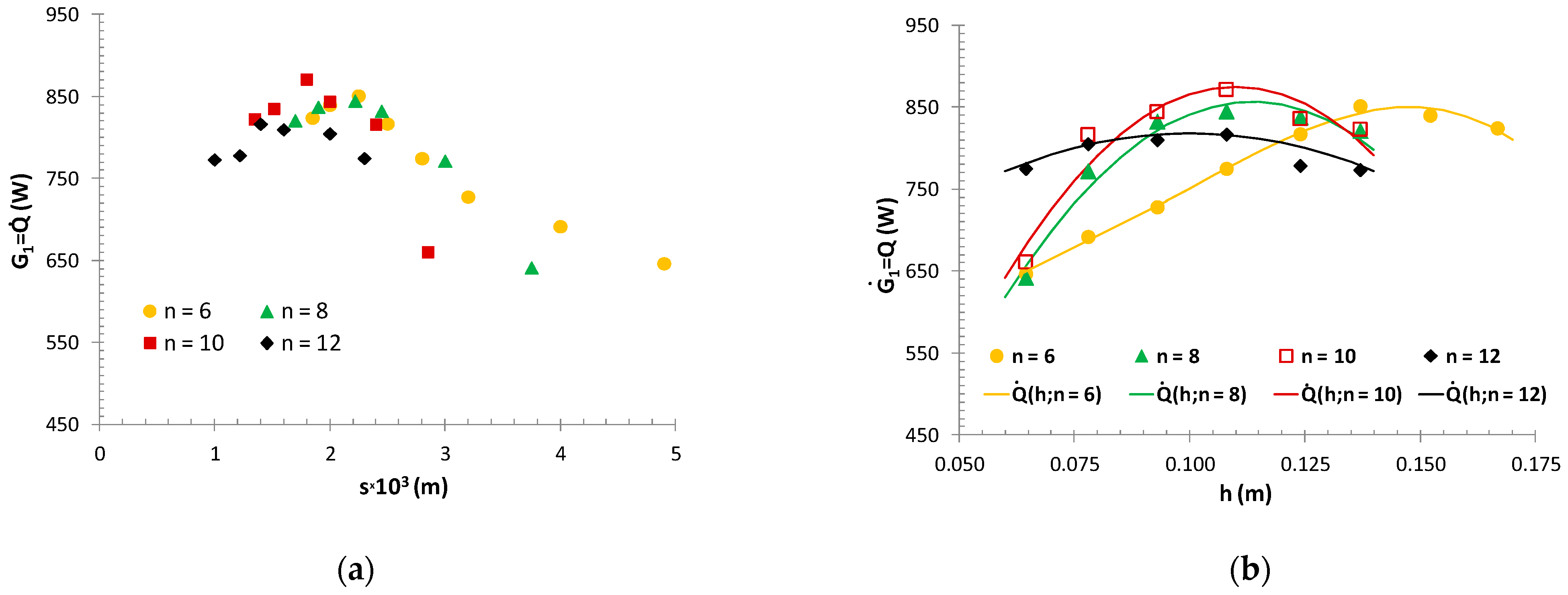
The solution to the problem defined by Equation (2) required several dozen simulations for different geometric models with variable parameters: n, h, s. Due to the assumption of a constant internal diameter of the profile and the diameter of the fin base, the variable mass of the profile corresponded to the mass of the fins mounted on the tube. Therefore, the calculations were carried out with the equality constraint (Equation (3)), in which the mass MPR = const. corresponded to the mass of the fins of the tested exchanger model MPR = MPR-M ≈ 10.77 kg. The changed number of fins n, and their equivalent height h, allowed determination of the required fin thickness s from the relationship in Equation (3). The objective function domain was defined by inequalities in Equations (5)–(7). The results obtained from the simulation are presented in Figure 5. Analysing the results presented in Figure 5, one can see that for a specified number of fins, there is an optimal height and thickness of the fin at which the exchanger achieves the highest efficiency, while maintaining a constant mass of the profile. For the adopted assumptions, the optimum height of the fin depended on the number of fins and was about 0.1–0.16 m, while the thickness of the fin should be in the range of 1.5 < s < 2.2 mm. The highest efficiency would be achieved with a number of fins equal to n = 10. In the case of n = 12 fins both the thickness and height of the fins had less influence on the efficiency of the exchanger than the number of fins n < 12. This means that a large number of fins had dominant effect on the efficiency achieved, with the effectiveness of the heat removal by individual fins decreasing. With lower numbers of fins, the maximum values of the target function moved in the direction of higher values of the height and thickness of the fins, which is a consequence of meeting the equality constraint (Equation (3)). Figure 5 allows defines indicative values of geometric parameters for which the thermal efficiency of the evaporator tube is at maximum value. In order to precisely determine the maximum of the objective function G1, for profiles with a fixed number of fins, the relation G 1 = Q ˙ ( h , n = c o n s t ) was parametrised.
The relationship G 1 = Q ˙ ( h , n = c o n s t ) is described by the functions of the form in Equation (9), with coefficients listed in Table 1.
Q ˙ * ( h ,   n   = c o n s t ) =   i   =   0 3 ( a i · h i )         w h e r e       n   =   6 ,   8 ,   10 ,   12
In Figure 5b, the continuous line marks the course of the function form (Equation (9)) and points ( Q ˙ , h ) corresponding to the results of simulation calculations. The relative differences between the efficiency values obtained were small, up to ±3.5%. Optimal values of geometric parameters h, s, for a certain number of fins, determined as a maximum of function (Equation (9)) are given in Table 2. The extremes values for function (Equation (9)) in the considered function domain were determined algebraically. The maximum thermal efficiency of a single heat pump evaporator tube (evaporator) of Q ˙ m a x =   875 W was achieved for the geometric parameters of the tube (n, h, s) of 10, 0.11 m, 1.80 mm, respectively. The optimisation results indicate that in case of finned surfaces, the optimal geometric parameters are moderate fin heights as well as their moderate numbers.
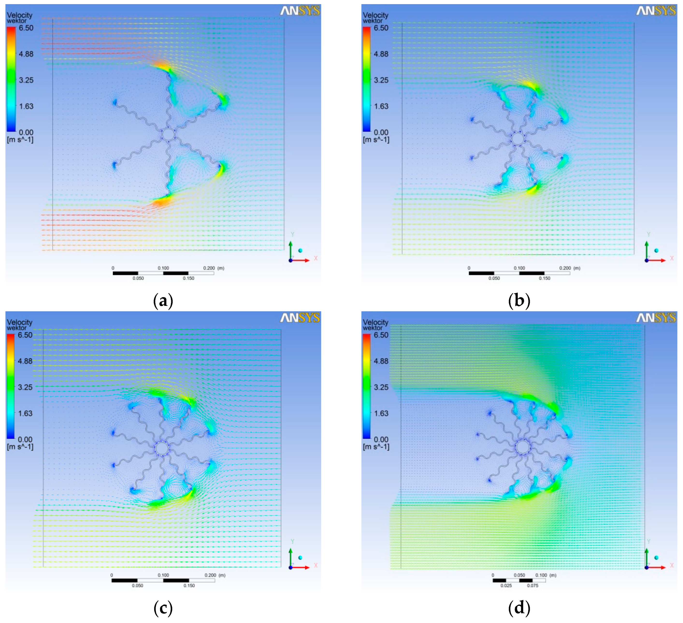
For a constant mass of fins, a low number of fins (n = 6) implies higher fins, while a large number of fins (n = 12) results in thinner fins. In both of these cases, the efficiency of the fins ( ε n = ( T a T ¯ f i n ) / ( T a T ¯ w o u t ) ) is the lowest (εn=6 ≈ 0.53; εn=12 ≈ 0.56). The fin efficiency values for cases n = 8 and n = 10 were, respectively, (εn=8≈0.61; εn=10≈0.59). In addition, in the case of short fins, higher values of the heat transfer coefficients promoted more intensive heating of the fins, which further reduced their efficiency. Both long fins and their large number (low spacing) make it difficult for warm outside air to come into contact with the base of the fin and the part of the fin where surface temperatures are the lowest. This effect can be observed in Figure 6 showing the distribution of air flow rate in the model cross-section. For a small number of long fins (n = 6), larger airflow effects occur between fins 1–2 and 5–6. Fins 1 and 6 and partly 2 and 5 operate effectively. The large number of fins n = 12 results in the airflow around the finned tube which is more similar to washing out a cylinder with a diameter corresponding to that of the fins. Small air streams entering between fins 1–4 and 8–12 do not reach the base of the fin.
Therefore, in this case not all of the fins work effectively and not along their entire length. In each of the cases under consideration, the fins on the leeward side are not very much involved in the heat transfer process. Thus, in case of a large number of fins, more of them can be eliminated from the heat transfer process. It should be remembered, however, that the actual conditions of the evaporator operation force full symmetry of the tube fins.
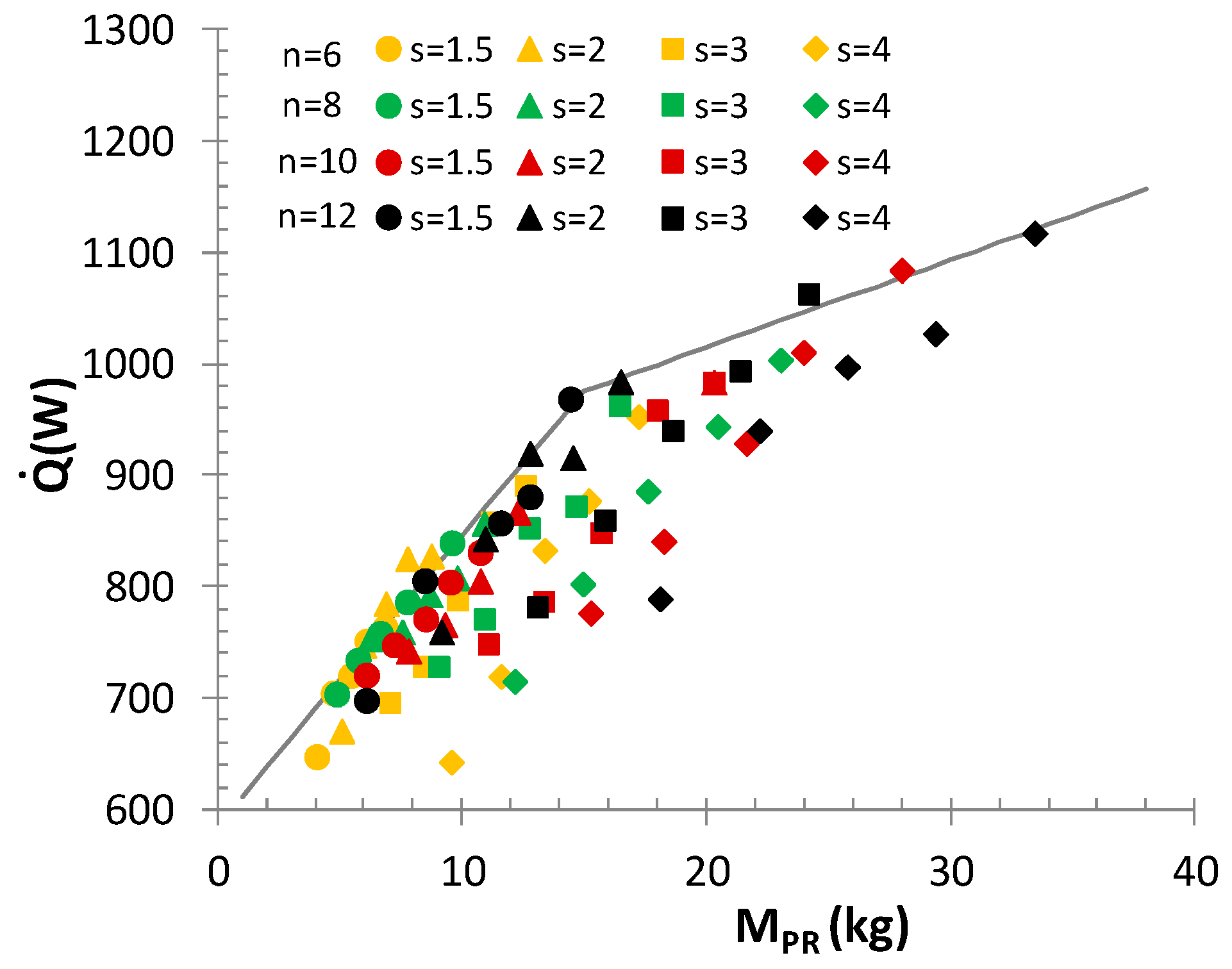
A wide database obtained during the simulation calculations enabled drawing the diagram of the dependence of the maximum thermal efficiency of the evaporator tube profile on its mass (Figure 7). Within the assumed range of parameter variability (n, h, s), the results presented in Figure 7 allow determinations for any mass of fins MPR, the maximum efficiency of the evaporator tube or the minimum mass for the assumed exchanger efficiency. The set of evaporator tube efficiency values is limited from above by the function values described in Equation (10). Two ranges separated in the domain of function Q ˙ m a x ( M PR ) result from the accepted constraints in the changes of the geometric parameters defined by inequalities (Equations (5)–(7)).
G 3 = Q ˙ m a x ( M PR ) =     { 25.95 · M PR + 585.8       f o r     M PR < 15   kg   7.85 · M PR + 857.5       f o r     M PR 15   kg
The results shown in Figure 7 indicate that for the constant mass condition, thinner and longer fins enable obtain higher thermal efficiency. The limitation of the fin height (aesthetic and technological reasons) makes it necessary to use a sufficient number of fins (e.g., n = 12) for the required higher efficiency.
The thermal performance values obtained from all the simulations carried out (Figure 4b and Figure 7) were described for the individual number of fins, with the function in the form of Equation (11). Function coefficients G 4 = Q ˙ ( h , s ) are listed in Table 3.
G 4 n = Q ˙ n ( h , s ) = b o n + b 1 n h + b 2 n s           f o r       n =   6 , 8 , 10 , 12
The procedure of determining optimal geometric parameters (n, s, h) for any mass within the considered range of changes in geometric parameters (Equations (5)–(7)), mass of profile 4 ≤ MPR ≤ 33.4 kg, thermal efficiency 648     Q ˙     1118 W requires solving the system of Equations (3), (10) and (11) for the assumed values of the number of fins n.

4. Conclusions

The results of optimisation calculations presented in the article are related to longitudinally finned tubes of a heat pump evaporator operating under natural air flow conditions. The finned surface was characterised by an unusual, wavy fin shape with a constant cross-section. The article presents the methodology applied to seeking optimal geometric parameters of the finned tube (number of fins, fin height, fin thickness), in which thermal calculations were performed by modelling the mixed convection process on the finned surface using the finite volume method (ANSYS).
The issue of optimisation was solved for two forms of the objective function with inequality and equality constraints. In the case of maximising the heat flow with the minimum mass of the fins, the optimal solution was dominated by the minimum mass of the fins and thus geometric parameters corresponding to the number of fins n = 6, fin height h = 0.065 m, fin thickness s = 0.0015 m. Optimisation calculations made for the maximum efficiency of the exchanger at constant mass (corresponding to the mass of the fins of the exchanger model) indicated that it is more advantageous to use a moderate number of longer and thinner fins. Too small or too large a number of fins reduces their efficiency. In the case under consideration, a L = 2 m tube with ten fins (n = 10) with a height of h = 0.11 m and a thickness of s = 0.0018 m allowed to a maximum efficiency of Q ˙ = 875 W at the assumed mass of the fins of MPR ≈ 10.77 kg. The limitations of the objective function domain (in particular, fin height) indicated that more fins are necessary for the required higher efficiency.
The optimisation issues considered concerned the operation of the evaporator without frost. These evaporator constructions could be operated under severe frost conditions. The release of latent heat from the air improves heat exchange conditions and heat transfer coefficient values, while reducing the efficiency of the fins (higher temperature difference between mean fin temperature and fin base temperature). The effect of this phenomenon on the results of optimisation calculations may depend on the surface temperature of the exchanger. Considering the case of a constant mass of the fins and the positive surface temperature of the evaporator (no frosting), higher values of the heat transfer coefficients can nudge the optimal solutions towards shorter (thicker) fins and lower quantity of fins. In the case of frosting on the heat transfer surface, the values of the heat transfer coefficients are improved, but at the same time the resistance of heat conduction through the frosted fin increases. With a sufficient thickness of frost, the finned tube with optimal geometrical parameters is characterised by an increased height and quantity of the fins. One interesting issue is the optimisation of the geometry of evaporator tubes in the conditions of condensation of moisture from the air and its frosting, which may be the subject of future studies.

5. Patents

Longitudinal finned tube protected as utility model no. PL 66649, 2011.

Author Contributions

Methodology, formal analysis, writing—original draft preparation, review and editing, B.N.-Ż.; software, validation, data curation, visualization, P.K. All authors have read and agreed to the published version of the manuscript.

Funding

This research in the measurements part was funded by National Science Centre Poland (Polskie Narodowe Centrum Nauki) as part of the research programme N N512 458040.

Institutional Review Board Statement

Not applicable.

Informed Consent Statement

Not applicable.

Data Availability Statement

Data is contained within the article.

Conflicts of Interest

The authors declare no conflict of interest.

Nomenclature

Asurface area, (m2)
aicoefficients in the Equation (9)
dtube diameter, (m)
Dfinfin diameter, (m)
Giobjective function, (W), (Wkg−1)
hequivalent fin height, (m)
hfinactual fin height, (m)
llength, (m)
Ltube height, (m)
MPRfin mass, (kg)
nnumber of fins
ppressure, (Pa)
Q ˙ * heat flow in the Equation (9), (W)
Q ˙ heat flow, (W)
sfin thickness, (m),(mm)
tfin spacing, (m),(mm)
Ttemperature, (°C)
waverage flow rate, ms−1
Symbols
αheat transfer coefficient, (Wm−2K−1)
εfin efficiency
φrelative humidity, (%)
ρAlaluminium density (ρAl = 2720), (kgm−3)
Indices
aair
bottbottom
CFD–CFD numerical calculations
expexperimental value
finrelated to the finned area
inrelated to the internal surface
loclocal value
Mrelated to the exchanger tubes profile model
maxmaximum value
optoptimal value
outrelated to the external surface
PRfin mass
topon top
wwall

References

  1. Daikin Systemy Grzewcze. Daikin_katalog_2012_Ogrzewanie. Available online: https://www.daikin.pl/pl_pl/customers.html (accessed on 10 December 2020).
  2. Niezgoda-Żelasko, B.; Zalewski, W.; Żelasko, J. Development of Technology and Technical Documentation and Testing of a Prototype of an Air-to-Water Heat Pump, Targeted Project No. ROW-II-436/2008; Cracow University of Technology: Kraków, Poland, 2008. [Google Scholar]
  3. Octopus Heat Pumps is an Efficient Solution. Available online: http://www.the-green-house.net/octopus-heat-pumps-is-an-efficient-solution/ (accessed on 16 September 2011).
  4. Niezgoda-Żelasko, B. Intensification of the Process of Heat Exchange in Evaporators of Air Heat Pumps Working at Low Airflow Velocities; Raport of Project N N512 458040; Cracow University of Technology: Kraków, Poland, 2013. [Google Scholar]
  5. Niezgoda-Żelasko, B.; Żelasko, J. Free and forced convection on the outer surface of vertical longitudinally finned tubes. Exp. Therm. Fluid Sci. 2014, 57, 145–156. [Google Scholar] [CrossRef]
  6. Acharya, S.; Patankar, S.V. Laminar Mixed Convection in a Shrouded Fin Array. J. Heat Transf. 1981, 103, 559–565. [Google Scholar] [CrossRef]
  7. Maughan, J.R.; Incropera, F.P. Mixed Convection Heat Transfer with Longitudinal Fins in a Horizontal Parallel Plate Channel: Part I—Numerical Results. J. Heat Transf. 1990, 112, 612–618. [Google Scholar] [CrossRef]
  8. Dogan, M.; Sivrioglu, M. Experimental investigation of mixed convection heat transfer from longitudinal fins in a horizontal rectangular channel: In natural convection dominated flow regimes. Energy Convers. Manag. 2009, 50, 2513–2521. [Google Scholar] [CrossRef]
  9. Dogan, M.; Sivrioglu, M. Experimental investigation of mixed convection heat transfer from longitudinal fins in a horizontal rectangular channel. Int. J. Heat Mass Transf. 2010, 53, 2149–2158. [Google Scholar] [CrossRef]
  10. Dogan, M.; Sivrioglu, M. Experimental and numerical investigation of clearance gap effects on laminar mixed convection heat transfer from fin array in a horizontal channel-A conjugate analysis. Appl. Therm. Eng. 2012, 40, 102–113. [Google Scholar] [CrossRef]
  11. Zhang, Z.; Patankar, S. Influence of buoyancy on the vertical flow and heat transfer in a shrouded fin array. Int. J. Heat Mass Transf. 1984, 27, 137–140. [Google Scholar] [CrossRef]
  12. Al-Sarkhi, A.; Abu-Nada, E.; Akash, B.A.; Jaber, J. Numerical investigation of shrouded fin array under combined free and forced convection. Int. Commun. Heat Mass Transf. 2003, 30, 435–444. [Google Scholar] [CrossRef]
  13. Petrone, G.; Cammarata, G. Numerical and experimnetal analysis of natural and mixed convection heat transfer for vertically arranged DIMM. In Proceedings of the COMSOL Conference, Hannover, Germany, 4–6 November 2008. [Google Scholar]
  14. Das, B. Mixed Convection Heat Transfer from A Shrouded Fin Array with and without Vortex Generator. Ph.D. Thesis, Deemed University, Arunachal Pradesh, India, 2014. [Google Scholar]
  15. Razelos, P. A note on the heat transfer in convective fins. Wärme Stoffübertrag. 1979, 12, 113–119. [Google Scholar] [CrossRef]
  16. Bhargava, S.; Duffin, R.J. On the Nonlinear Method of Wilkins for Cooling Fin Optimization. SIAM J. Appl. Math. 1973, 24, 441–448. [Google Scholar] [CrossRef] [Green Version]
  17. Mikk, I. Convective fin of minimum mass. Int. J. Heat Mass Transf. 1980, 23, 707–711. [Google Scholar] [CrossRef]
  18. Maday, C.J. The Minimum Weight One-Dimensional Straight Cooling Fin. J. Eng. Ind. 1974, 96, 161–165. [Google Scholar] [CrossRef]
  19. Ahmadi, G.; Razani, A. Some optimization problems related to cooling fins. Int. J. Heat Mass Transf. 1973, 16, 2369–2375. [Google Scholar] [CrossRef]
  20. Chung, B.T.F.; Zhang, B.X. Optimization of Radiating Fin Array Including Mutual Irradiations Between Radiator Elements. J. Heat Transf. 1991, 113, 814–822. [Google Scholar] [CrossRef]
  21. Kern, J. Zur Bewertung von Kompakt-Wärmetauschern. Wärme Stoffübertrag. 1980, 13, 205–215. [Google Scholar] [CrossRef]
  22. Unk, J. Verfahren zur Optimierung von Rippenrohren und der Rohrreihenzahl in Wärmerückgewinnunggeräten. Klima Kälte Heizung 1981, 2, 73–79. [Google Scholar]
  23. Bulck, E.V.D. Optimal Design of Crossflow Heat Exchangers. J. Heat Transf. 1991, 113, 341–347. [Google Scholar] [CrossRef]
  24. Niezgoda, B. Minimising Investment and Operating Costs of Heat Exchangers with Developed Heat Exchange Surfaces. Ph.D. Thesis, Cracow University of Technology, Kraków, Poland, 1992. [Google Scholar]
  25. Niezgoda, B. Optymalizacja termiczno-przepływowych parametrów pracy ożebrowanych wymienników ciepła (Optimisa-tion of thermal-flow parameters of finned heat exchangers). Techn. Trans. 1995, Z.-1, 126–135. [Google Scholar]
  26. Niezgoda-Żelasko, B.; Zalewski, W.; Pacześna, J. Optymalizacja podziałki rozstawienia lamel w chłodnicach cieczy i skraplaczach chłodzonych powietrzem (Optimisation of fin spacing in liquid coolers and air-cooled condensers). Tech. Chłod. Klim. 2000, 6, 235–239. [Google Scholar]
  27. Maltson, J.D.; Wilcock, D.; Davenport, C.J. Comparative performance of rippled fine plate fin and tube heat exchanger. J. Heat Transf. 1989, 111, 21–28. [Google Scholar] [CrossRef]
  28. Ko, T. Thermodynamic analysis of optimal curvature ratio for fully developed laminar forced convection in a helical coiled tube with uniform heat flux. Int. J. Therm. Sci. 2006, 45, 729–737. [Google Scholar] [CrossRef]
  29. Rustum, I.; Soliman, H. Numerical analysis of laminar mixed convection in horizontal internally finned tubes. Int. J. Heat Mass Transf. 1990, 33, 1485–1496. [Google Scholar] [CrossRef]
  30. Chai, J.C.; Patankar, S.V. Natural laminar convection in internally finned horizontal annuli. Numer. Heat Transf. Part A 1993, 24, 67–87. [Google Scholar] [CrossRef]
  31. Haldar, S.; Kochhar, G.; Manohar, K.; Sahoo, R. Numerical study of laminar free convection about a horizontal cylinder with longitudinal fins of finite thickness. Int. J. Therm. Sci. 2007, 46, 692–698. [Google Scholar] [CrossRef]
  32. Haldar, S.C. Laminar Free Convection Around a Horizontal Cylinder with External Longitudinal Fins. Heat Transf. Eng. 2004, 25, 45–53. [Google Scholar] [CrossRef]
  33. Farinas, M.-I.; Garon, A.; Saint-Louis, K. Study of heat transfer in a horizontal cylinder with fins. Rev. Gén. Therm. 1997, 36, 398–410. [Google Scholar] [CrossRef]
  34. Ibrahim, E.; Moawed, M. Forced convection and entropy generation from elliptic tubes with longitudinal fins. Energy Convers. Manag. 2009, 50, 1946–1954. [Google Scholar] [CrossRef]
  35. Kundu, B. Beneficial design of unbaffled shell-and-tube heat exchangers for attachment of longitudinal fins with trapezoidal profile. Case Stud. Therm. Eng. 2015, 5, 104–112. [Google Scholar] [CrossRef] [Green Version]
  36. Lin, M.; Wang, Q.W. Turbulent heat transfer performance of internally longitudinally finned tubes. WIT Trans. State Art Sci. Eng. 2013, 63, 185–210. [Google Scholar]
  37. Awasarmol Umesh, V.; Pise Ashok, T. An experimental investigation of natural convection heat transfer anhancement from perforated rectangular fins array at different inclinations. Exp. Therm. Fluid Sci. 2015, 68, 145–154. [Google Scholar] [CrossRef]
  38. Kast, W.; Klan, H. Wärmeübergang durch freie Konvection an umströmten Körpern. In VDI-Wärmeatlas; VDI: Düsseldorf, Germany, 1991; pp. Fa1–Fa7. [Google Scholar]
  39. Yazicioglu, B. Performance of Rectangular Fins on a Vertical Base in Free Convection Heat Transfer. Master’s Thesis, Middle East Technical University, Ankara, Turkey, 2005. [Google Scholar]
  40. Gnielinski, V. Wärmeübergang bei erzwungener einphasiger Strömung. In VDI-Wärmeatlas; VDI: Düsseldorf, Germany, 1991; pp. Ga1–Ga2. [Google Scholar]
  41. Mahdi, Q.S.; Abbod, S.A.; Abbas, F.A. Investigation of heat transfer augmention from U-longitudinal finned tube heat ex-changer. Adv. Energy Power 2015, 3, 19–28. [Google Scholar] [CrossRef]
  42. Pronobis, M. Prenos tepla ve svazcich zebrovanych trubek. Energetika 1987, 12, 572–575. [Google Scholar]
  43. Kopeć, P.; Niezgoda-Żelasko, B. Heat transfer on the outer surface of vertical longitudinally finned tubes. In IOP Conference Series: Earth and Environmental Science; IOP Publishing: Bristol, UK, 2019; Volume 214, p. 012058. [Google Scholar]
  44. Ansys Fluent Theory Guide; Relase 14.0. 2011. Available online: https://www.scribd.com/doc/140163341/Ansys-Fluent-14-0-Theory-Guide (accessed on 10 December 2020).
  45. Kopeć, P.; Niezgoda-Żelasko, B. Modeling of the heat transfer process in an air heat pump fanless evaporator. MATEC Web Conf. 2018, 240, 05012. [Google Scholar] [CrossRef]
  46. Niezgoda-Żelasko, B.; Żelasko, J.; Zalewski, W. Longitudinal Finned Tube, Utility Model No. PL 66649; Patent Office of the Republic of Poland: Warszawa, Poland, 2011. [Google Scholar]
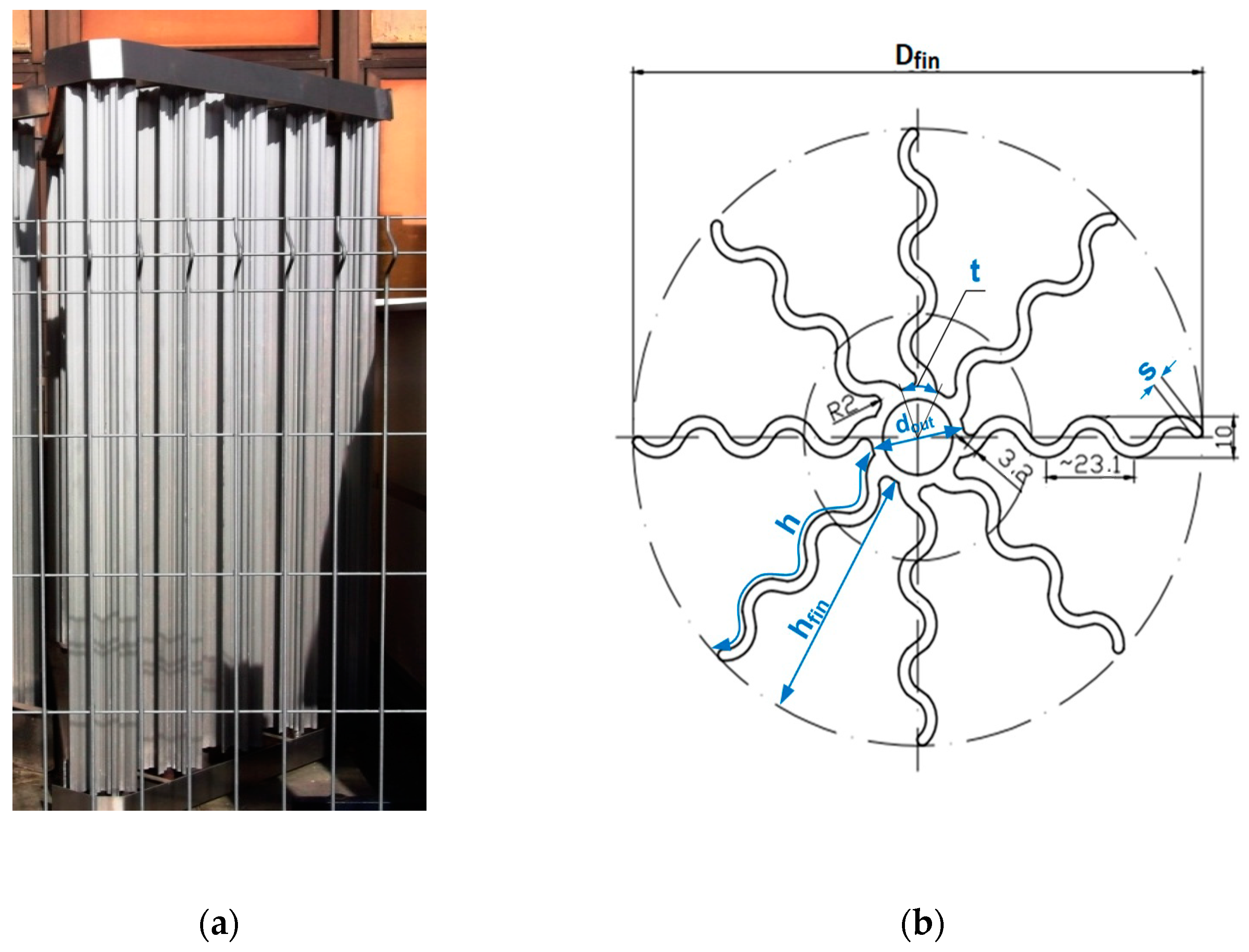
Figure 1. Heat pump evaporator: (a) view of the example design; (b) cross section of the aluminium profile mounted on the copper tube of the evaporator.
Processes 09 00111 g001
Figure 2. Geometric model of calculations with assumed boundary conditions, (1;8)—fin number, lbot, ltop—location of the measurement surfaces of temperature distribution and heat transfer coefficients.
Processes 09 00111 g002
Figure 3. Verification of the calculation model, mixed convection wa = 2.3 ms−1, Δ T = Δ T ¯ a Δ T ¯ w a l l =   25   K : (a) temperature distribution for fin at height lbot = 0.2 m; (b) temperature distribution for fin at height ltop = 1.6 m; (c) local values of the fin base and end; (d) local values of heat transfer coefficients.
Processes 09 00111 g003
Figure 4. Objective function values G 2 = Q ˙ / M PR : (a) as a function of the profile mass; (b) as a function of the fin height and thickness for n = 6 fins mounted on the tube.
Processes 09 00111 g004
Figure 5. Change in the value of the objective function G 1 for MPR = MPR-M depending on: (a) fin thickness; (b) fin height.
Processes 09 00111 g005
Figure 6. Distribution of air flow rate in the cross-section of the model L = 1 m: (a) n = 6; (b) n = 8; (c) n = 10; (d) n = 12.
Processes 09 00111 g006
Figure 7. Relationship between the efficiency and mass of evaporator tube fins Q ˙ ( M PR ) .
Processes 09 00111 g007
Table 1. Coefficients in Equation (9).
na0a1a2a3
6977.2112,520.23152,116.83495,515.85
8−216.6018,905.33−83,271.520
10−250.1420,449.23−92,935.40
12518.156109.04−32,099.0110,132.31
Table 2. Optimal values of the geometric parameters of evaporator tubes.
n Q ˙ m a x   2 ( W ) hopt3(m)sopt × 103 (m)
68500.1602.24
88560.1142.19
10 18750.1101.80
128180.1001.65
1 Optimal solution, 2 max—maximum value, 3 opt—optimal value.
Table 3. Coefficients in Equation (11).
nb0b1b2
61095.59−24.25−149.54
81194.83−25.33−234.25
101344.47−30.56−354.91
121434.12−31.42−410.01
Publisher’s Note: MDPI stays neutral with regard to jurisdictional claims in published maps and institutional affiliations.