Article

Investigation on the Performance Enhancement and Emission Reduction of a Biodiesel Fueled Diesel Engine Based on an Improved Entire Diesel Engine Simulation Model

1
Hunan Valin Xiangtan Iron & Steel Co., Ltd., Xiangtan 411101, China
2
School of Mechanical and Transportation Engineering, Guangxi University of Science and Technology, Liuzhou 545006, China
3
School of Electrical Engineering, Hunan Institute of Engineering, Xiangtan 411104, China
*
Author to whom correspondence should be addressed.
Processes 2021, 9(1), 104; https://doi.org/10.3390/pr9010104
Submission received: 5 December 2020 / Revised: 24 December 2020 / Accepted: 31 December 2020 / Published: 6 January 2021
(This article belongs to the Special Issue Energy Conservation and Emission Reduction in Process Industry)

Abstract

:
In order to improve the efficiency of the diesel engine and reduce emissions, an improved heat transfer model was developed in an AVL-BOOST environment which is a powerful and user-friendly software for engine steady-state and transient performance analysis. The improved heat transfer model considers the advantages of the Woschni1978 heat transfer model and Honhenberg heat transfer model. In addition, a five-component biodiesel skeletal mechanism containing 475 reactions and 134 species was developed to simulate the fuel spray process and combustion process since it contained methyl linolenate, methyl linoleate, methyl oleate, methyl stearate, and methyl palmitate, which are a majority component in most biodiesel. Finally, the propulsion and load characteristics of a diesel engine fueled with biodiesel fuel were investigated by the improved heat transfer model in term of power, brake specific fuel consumption (BSFC), soot and NOx emissions. Similarly, the effects of the fuel injection rate on the diesel engine’s characteristic fueled with biodiesel was studied. The result showed that the errors between experiment and simulation were less than 2%. Thus, the simulation model could predict the propulsion and load characteristics of the diesel engine. The nozzle diameter, injection pressure, and injection advance angle are significant to the injection system. Thus, it is very important to choose the injection rate reasonably.

1. Introduction

Due to the reliability and economy of diesel engine [1], the diesel engine has become the main power source for mechanical equipment [2], such as the ship, construction machinery [3], and heavy-duty trucks [4]. Particulate matter (PM) and NOx emission from diesel engines pose a threat to the ecosystem and public health [5]. With the supplementary provisions that have been implemented one after another [5] requires knowledge on how to reduce NOx and PM emissions [6] and how to improve the characteristics of the diesel engine [7]. In order to meet the requirements of regulations [8], it is necessary to develop renewable energy to replace fossil fuels [9] and improve the system structure of existing diesel engines so as to adapt the new fuel [10,11,12].
The diesel engine combustion is a physical and chemical process, which is complex and changeable. In order to improve the efficiency of diesel engine and reduce the cost [13], the numerical method has often been applied to select an alternative option [14] and improve the design with limited resources [15]. The designer only chose the corresponding model and input the diesel engine parameters [16], then the designer could make a preliminary demonstration of the model because the modeling and simulation software provides a pre-design platform [17]. For instance, Lino and Maione developed the nonlinear injection system model of a common rail diesel engine with AMESim software [18]. They found that the model verified by experiment could accurately predict the good spray performance and improved the combustion process of diesel engine. Lähde et al. had established an injection system simulation model of an electronic control unit (ECU) pump and investigated the effects of various structural parameters on the economy and emission characteristics of a diesel engine [19]. The results showed that the injection rate had a great influence on the emission and performance characteristics of a diesel engine. In addition, Fan et al. had developed a finite element mode of a ECU pump’s high-speed solenoid valve and analyzed the effects of various factors on the solenoid valve [20]. The result showed that the solenoid valve delay was an important factor in the spray performance. A one-dimensional fuel injection system model was proposed to discuss the influence of biodiesel on the performance characteristic of a common rail diesel engine by Frosina et al. [21]. The simulation results were in good agreement with the experimental results. The literatures concerning the emission and performance characteristics of diesel engine are plentiful, which mainly focuses on developing a model for the components of the fuel injection system, but the mechanical injection system transformation for the electronically-controlled injection system has received considerably less attention [22]. Therefore, the software provides a good platform for the modeling of a diesel engine injection system, and it can effectively analyze the spray performance, propulsion, and load characteristics of the diesel engine [23].
Typically, the zero-dimensional or double zone combustion models are developed by the GT-Power or ALV-BOOST software and the influences of input parameters on the comprehensive performance of the diesel engine are studied [24,25,26]. For instance, Gupta et al. had developed simulation models by AVL-BOOST and neural network software and investigated the relative contribution of operational parameters on emission and performance characteristics of a common-rail diesel engine in term of such as torque, soot, NOx, and brake specific fuel consumption (BSFC) [27]. Similarly, some scholars have established the simulation model of homogeneous charge compression ignition diesel and biogas fuel by using AVL-BOOST software, which were verified by test results, and analyzed the effects of a different fuel mixing ratio on the comprehensive characteristic of diesel engines [28,29,30]. Other scholars carried out the modeling and made the analysis of four main factors that could impact the performance and emission characteristics of a diesel engine, including the first and second injection mass ratio, interval time, main injection start time, and exhaust gas recirculation (EGR) ratio [31,32,33,34]. The one-dimensional models are simpler, faster, and include more detailed physical models [35]. In general, more advanced models such as combustion, heat transfer, and pollutant formation processes should be employed to simulate and improve the accuracy of the calculation [36]. However, the biodiesel as a good alternative of petrochemical energy is non-toxic [37], biodegradable and has significantly fewer emissions [38]. Thus, it is of great significance to study the injection performance and emission performance of biodiesel [39].
In the paper, the combined weight coefficient is employed to develop an improved heat transfer model, which is used to simulate the combustion and heat transfer processes of a diesel engine fueled with biodiesel fuel in an AVL-BOOST environment. In addition, a five-component biodiesel skeletal mechanism is also employed to predict the combustion process of biodiesel fuel. Then, the AVL-BOOST model is validated by the experimental results under different conditions. Moreover, the new developed model will be employed to analyze the engine characteristic and the effects of the fuel injection rate on the engine characteristic of diesel engine fueled with biodiesel fuel is investigated.

2. Methods and Model Validation

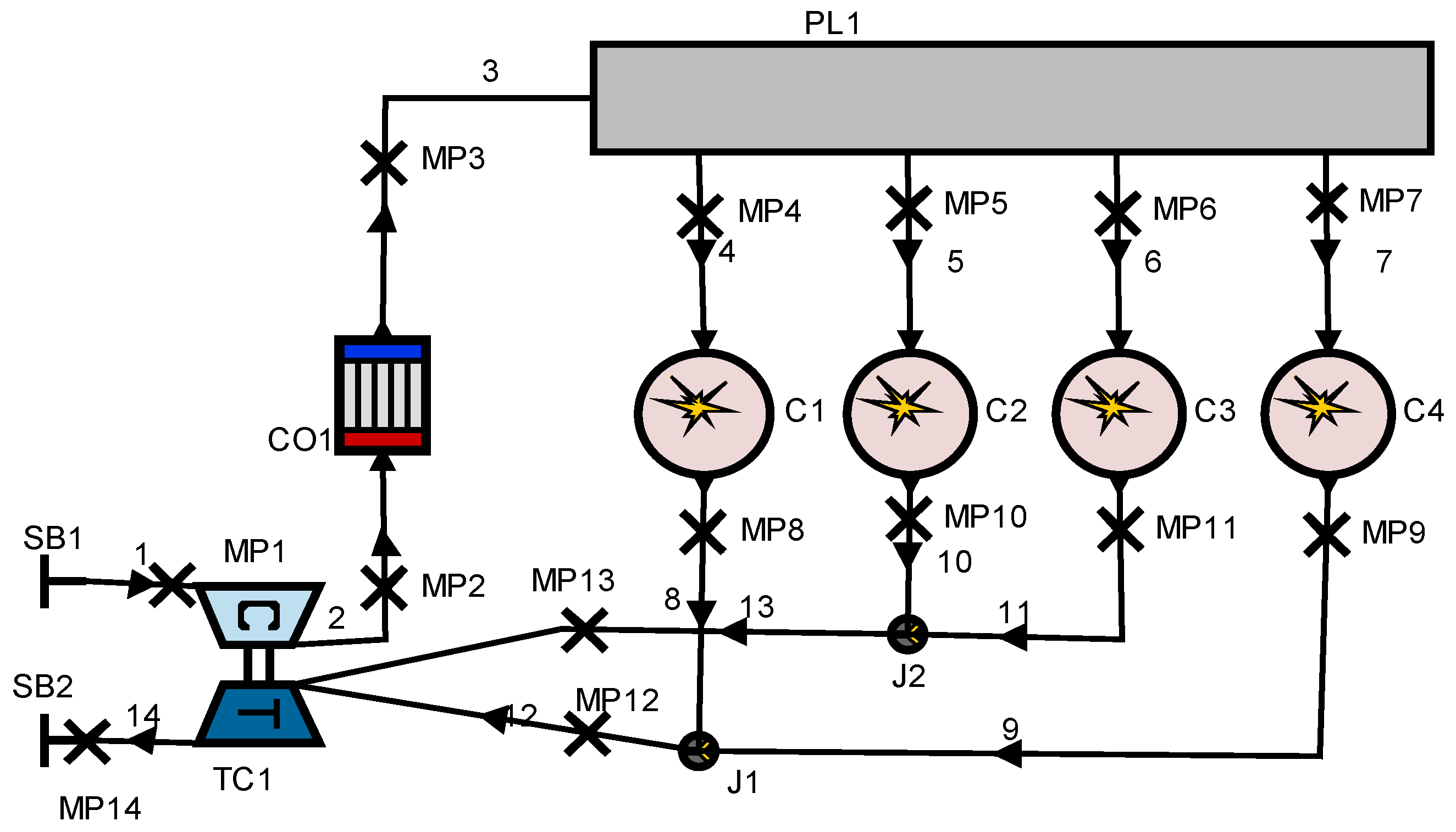
2.1. An Improved Entire Diesel Engine Simulation Model

(1) The combustion model
In order to improve the calculation accuracy, a quasi-dimensional MCC AVL combustion model is used to predict the combustion process in the cylinder. The model considers the influence of diffusion combustion and pre-mixing, and it can predict the emission characteristic of diesel engine accurately. The expression of heat release rate is expressed as follow:
d Q F d φ = d Q MCC d φ + d Q PMC d φ
where QF is the combustion heat release rate, QMCC is the total heat release rate of diffusion combustion, QPMC is the total heat release rate of pre-mixed combustion, and φ is the crank angle.
The total heat release rate of diffusion combustion is expressed as Equation (2):
d Q MCC d φ = C comb ( m F Q MCC H u ) ( w Air ) C EGR C Rate k V 3
where QMCC is the total heat release rate of diffusion combustion, Ccomb is the Combustion constant, mF is the evaporative fuel mass, Hu is the low calorific value of fuel oil, k is the turbulent energy density, wAir is the effective air mass fraction, CEGR is the EGR influence constant, and CRate is the mixing ratio constant.
The actual heat release rate of pre-mixed combustion is expressed as Equation (3):
1 Q P M C d Q P M C d φ = 6.908 Δ φ C ( m + 1 ) ( φ φ B Δ φ C ) exp [ 6.908 ( φ φ B Δ φ C ) ( m + 1 ) ]
where QPMC is the total heat release rate of pre-mixed combustion, φ is the crank angle, Δφc is the pre-mixed combustion duration, φB is the start of combustion angle, and m is the shape parameter.
(2) Combined heat transfer model
Heat transfer in a diesel cylinder is a very complicated process, in view of the heat transfer calculation of a high-pressure cycle, the Woschni1978 heat transfer model is generally used. In the heat transfer process, it mainly considers the influence of the convection heat transfer in the cylinder [32,33]. The Woschni model published in 1978 for the high-pressure cycle is summarized as follows:
α w = 130 T c - 0 . 2 p c 0 . 8 D 0.2 [ C 1 C m + C 2 V T IVC p IVC V IVC ( p c p c , o ) ] 0.8
where Tc is the cylinder temperature, pc is the cylinder pressure, D is the cylinder diameter, C1 is the gas velocity coefficient, Cm is the mean velocity of piston, C2 is the model constant, TIVC is the inlet valve closing cylinder volume, V is the actual cylinder volume, pIVC is the inlet valve closing cylinder pressure, and pc,o is the inverted cylinder pressure.
The heat transfer coefficient of the Honhenberg heat transfer model is summarized as follows:
α k = 130 V 0.06 p c 0.8 T c 0.4 ( c m + 1.4 ) 0.8
where pc is the cylinder pressure, Cm is the mean velocity of piston, and V is the actual cylinder volume.
A single heat transfer model is likely to have some defects and cannot accurately predict the heat transfer in the diesel engine’s cylinder. In order to improve the accuracy of the calculation and make up for the lack of a single model, an optimization weighted array model is developed to predict the heat transfer in a diesel cylinder based on the forecasting theory of the optimization weighted array. The optimal weighting coefficients are derived by the minimum variance method. Thus, the advantages of the two models are combined. The improvement of combined model makes the model more accurate.
It is assumed that αi is the expected predictive value and the experimental observation value is Xi (X1, X2, …, Xn). The predicted value of the Woschni1978 heat transfer model is αwi (i = 1, 2, …, n), the error between the model value and the test value is ewi (i = 1, 2, …, n). The predicted value of the second model is αki (i = 1, 2, …, n), the error between the second model value and test value is eki (i = 1, 2, …, n). Respectively, the expected predictive value of αi and error ei(i = 1, 2, …, n) are as follow:
αi = w1αwi + w2αki
where w1 is the weight coefficient of the Woschni1978 heat transfer model and w2 is the weight coefficient of the Honhenberg heat transfer model.
ei = w1ewi + w2eki
where e1i, e2i, w1, and w2 are defined as: w1 + w2 = 1, e1i = Xiαwi, e2i = Xiαki.
The minimum quadratic sum of the combined expected forecasting error is as follows:
min ( e i 2 ) = min [ w 1 2 e w i 2 + 2 w 1 w 2 ( e w i e k i ) + w 2 2 e k i 2 ]
with w 1 = [ e k i 2 ( e w i e k i ) ] / [ e w i 2 + e k i 2 2 ( e w i e k i ) ] and w 2 = [ e w i 2 ( e w i e k i ) ] / [ e w i 2 + e k i 2 2 ( e w i e k i ) ] .
It can be proved that min(∑ei2) ≤ min(∑eki2) and min(∑ei2) ≤ min(∑ewi2). Thus, the combined heat transfer model is better than the single model prediction.
(3) Simulation model establishment of an entire diesel engine
In order to investigate the steady state and transient state performance characteristics of a diesel engine, the entire model of the diesel engine was developed in an AVL-BOOST environment. Figure 1 shows the layout of the entire diesel engine. In addition, the main parameters of the diesel engine are shown in Table 1. The air cooled by the air cooler enters the cylinder through the air intake passage. After a combustion process, the exhaust gases are discharged and flow into the turbine inlet. The turbine drives the turbo-compressor, which delivers the compressed air to the cooler.

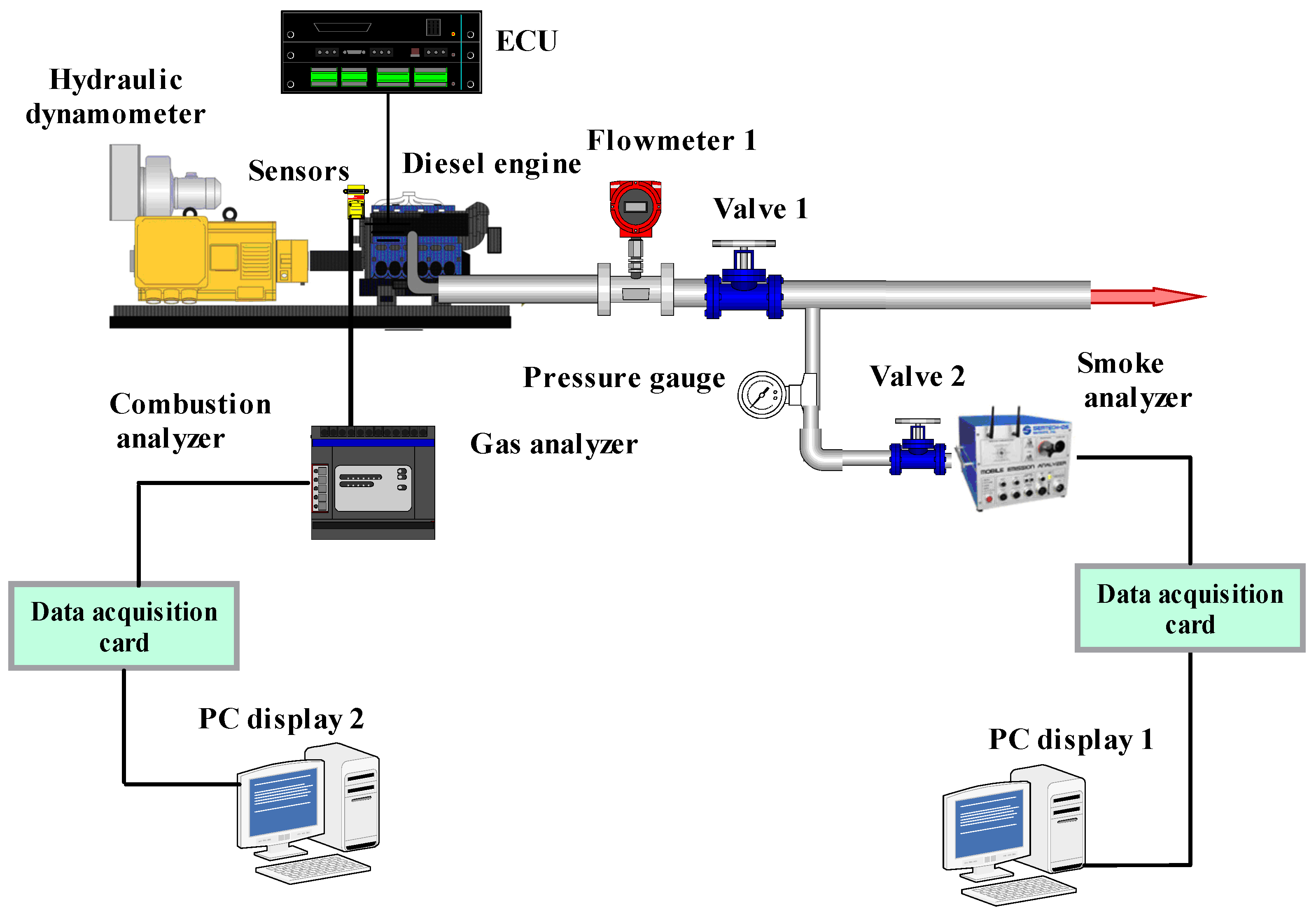
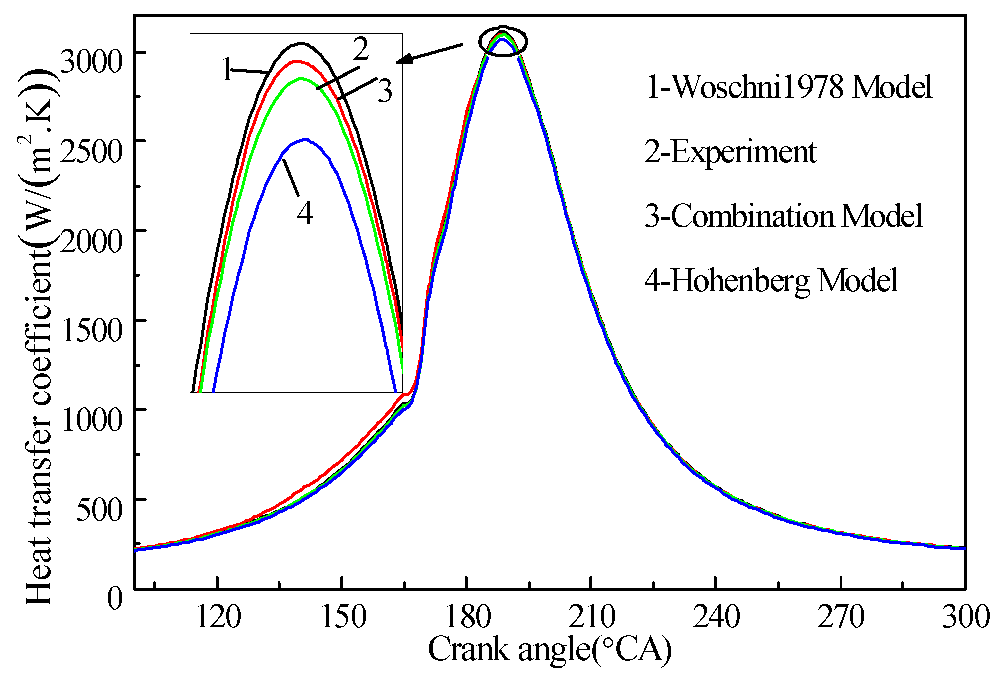
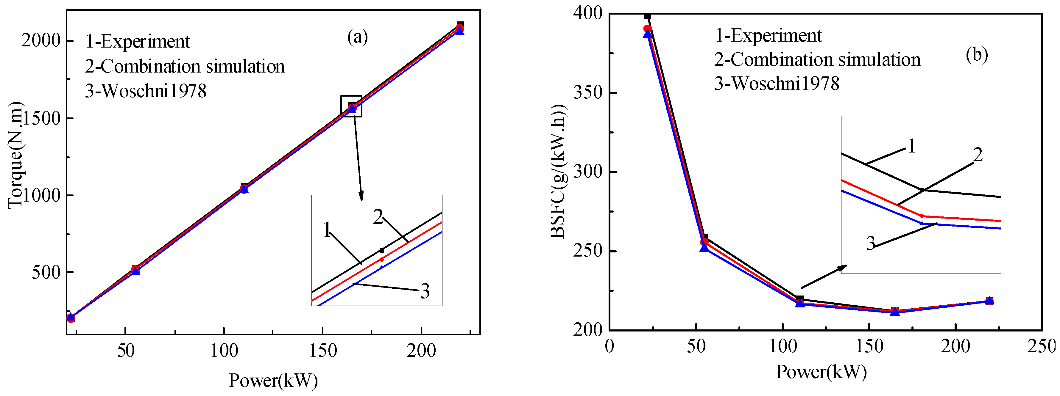
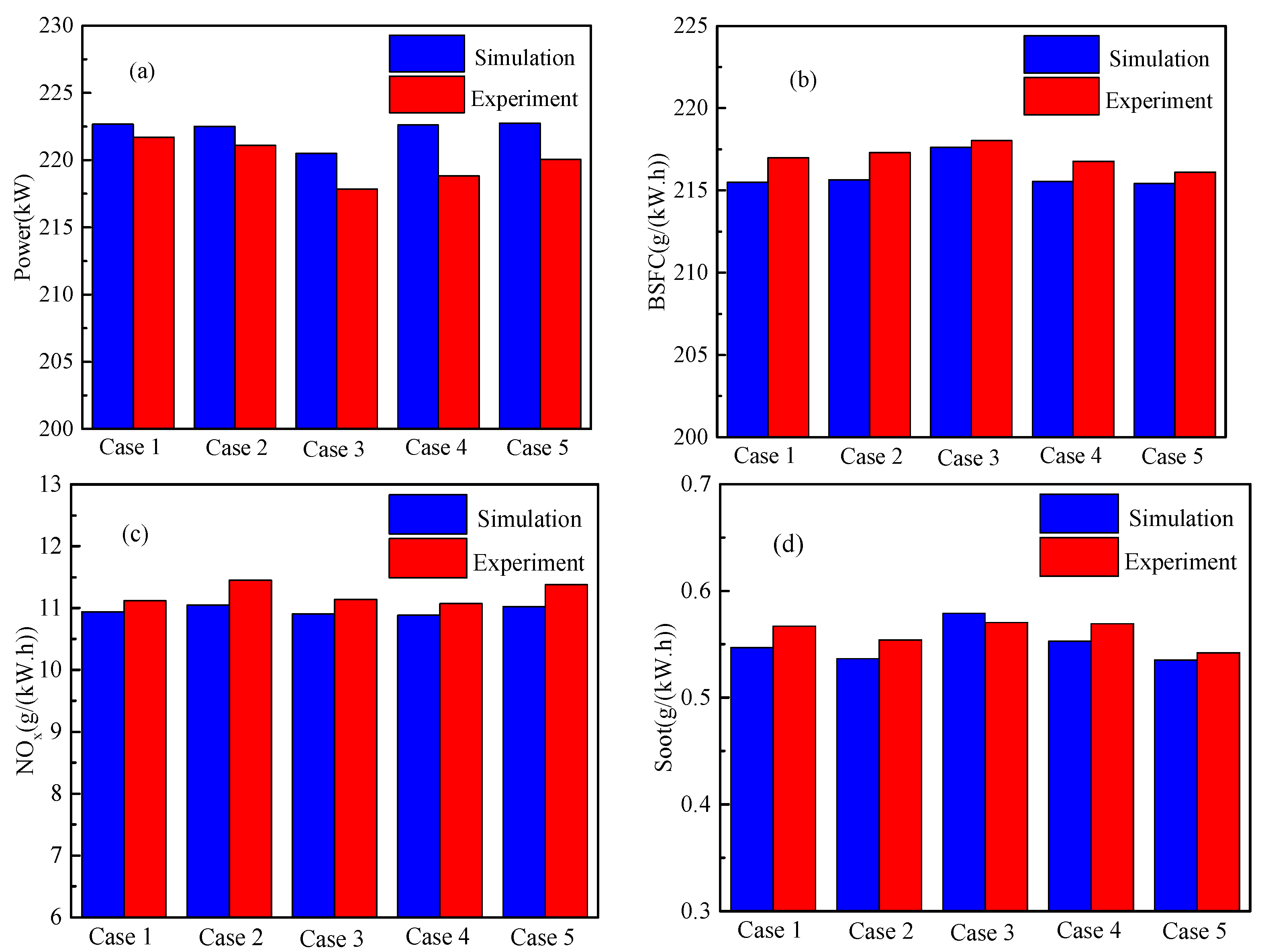
2.2. Model Validation

The instantaneous injection rate (IFR) and the fuel injection pressure can be obtained by the oil pump testing device (6PSDW300). The IFR system is composed of the electronic control part and mechanical part. Moreover, the IFR was measured by the EFS8427 measurement units of the French EFS company. The main experiment steps can be expressed as follows:
Step 1: Preparation work. Check the oil pump testing device, fill the low-pressure oil tank with fuel, and install the electronic unit pump in the mechanical part. The electronic control part is supplied by a single-phase current and connected to the computer through the Ethernet by a specific software as a user interface.
Step 2: Set the relevant operating parameters of the oil pump test bed. To start, motor drive oil pump operation and transport oil from the low-pressure oil tank to the high-pressure common rail pipe. Fuel that is injected from the fuel injector will be collected in a constant static pressure fuel collection chamber.
The main parameters of the fuel injection system (FIS) of the ECU pump are shown in Table 2. In the experimental process, the injection pressure and fuel supply pressure were measured by the pressure sensor installed in the mechanical part, and the original parameters such as the fuel injection rate and fuel injection mass were provided to the IFR control system.
Rapeseed is widely planted in south China and nearly half of the edible oil is rapeseed oil. Thus, the diesel engine fueled with rapeseed oil methyl ester (RME) is employed to carry out the experiment in this work. In our previous work, the RME could be obtained by the transesterification method [40]. Moreover, the biodiesel transesterification was carried out by alkali catalysis about 1.2 h in the experimental reactor. The transesterification conducted 1:6 oil molars to a methanol ratio with 1%wt/wt potassium hydroxide as the alkaline catalyst. The detailed process can be obtained in [40] in our previous work. The physical properties of biodiesel are shown in Table 3. The detailed biodiesel information could be obtained from the previously published works [40,41,42] of our team.
In order to validate the simulation result, the experiment was carried out on the experimental bench of a diesel engine. The Horiba MEXA-1600 was used for measuring generated NOx with a 1% error, while the AVL Dismoke-4000 was employed for measuring generated soot. FCMM-2 was used for measuring BFSC. DEWE-2010CA was employed for monitoring the combustion of a diesel engine. In addition, an ECU control system was employed for controlling the electronically-controlled diesel engine. EFS-IFR600 was employed for measuring the fuel injection rate with a 0.5% measuring error. A hydraulic dynamometer was used for measuring the diesel engine load. Moreover, the temperature, flow, and pressure were measured by suitable sensors. The schematics of experimental device are shown in Figure 2.
The typical biodiesels are mainly composed by five components, methyl linolenate, methyl linoleate, methyl oleate, methyl stearate, and methyl palmitate. Thus, a multi--component biodiesel skeletal mechanism, which was made up of the above five components, was employed to investigate the combustion process of biodiesel fuel consisting of 134 species and 475 reactions in the AVL-BOOST simulation environment. The detailed information can be obtained from the previously published works [40,41,42] of our team.
The combustion model is effective for considering the influence of the jet kinetic energy and fuel injection rate on the instantaneous heat release and can accurately predict the formations of nitrogen oxides and soot. Thus, the combustion in the cylinder is fitted with an AVL MCC combustion model. The AVL MCC combustion model is as follows:
d Q d φ = C M o d ( M F Q L C V ) exp ( C R a t e k V 3 )
where CMod is the model constant; CRate is the mixing rate constant; and LCV is the low calorific value of fuel oil.
The Chen–Flynn model is used to calculate the loss pressure due to the friction and the loss pressure is a function of piston speed and peak pressure in the AVL-BOOST simulation environment. In addition, the combined heat transfer model, Woschni1978 heat transfer model, and Honhenberg heat transfer model are employed to simulate the heat transfer process in the cylinder, respectively. In order to validate the combined model, the experiment was carried out and comparisons of the heat transfer coefficient are shown in Figure 3 at a 100% load. It can be found that a predicted result of the combined model is in agreement with the experimental results. Through a contrast experiment and correction, the predicted result of the combined model had the maximum error of 2.1%, but the predicted result of the Woschni1978 heat transfer model had a maximum error of 3.2%. Thus, the combined model can better predict the performance characteristic of the diesel engine.
In the paper, the effects of the length of a high-pressure oil pipe, nozzle diameter, and plunger diameter on the injection pressure and injection duration angle were considered. More specifically, the length of a high-pressure oil pipe (850 and 900 mm), nozzle diameter (0.24, 0.26, and 0.28 mm), and plunger diameter (13.5, 14 and 14.5 mm) were employed to investigate the injection characteristics. In the experimental process, the engine speed was 1000 rpm and the fuel injection mass remains constant. If the injection pressure is greater than 100 MPa and the injection duration angle is less than 35°, the case will be selected. Thus, the five cases selected are shown in Table 4. The engine characteristic of diesel engine fueled with RME is investigated in terms of power, BSFC, NOx, and soot emissions.

3. Results and Discussion

The experiments were carried out on four cylinders four-stroke. The load and speed of each test point are shown in Table 5. In order to avoid cross-contamination, the diesel engine fueled with RME operated for 25 min. In addition, in order to ensure the steady state measurement, the experimental results of each operating condition are recorded after running for 25 min. The experiments of each operating condition were carried out three times and the recorded results averaged. In addition, the injection characteristic of the diesel engine was also studied.

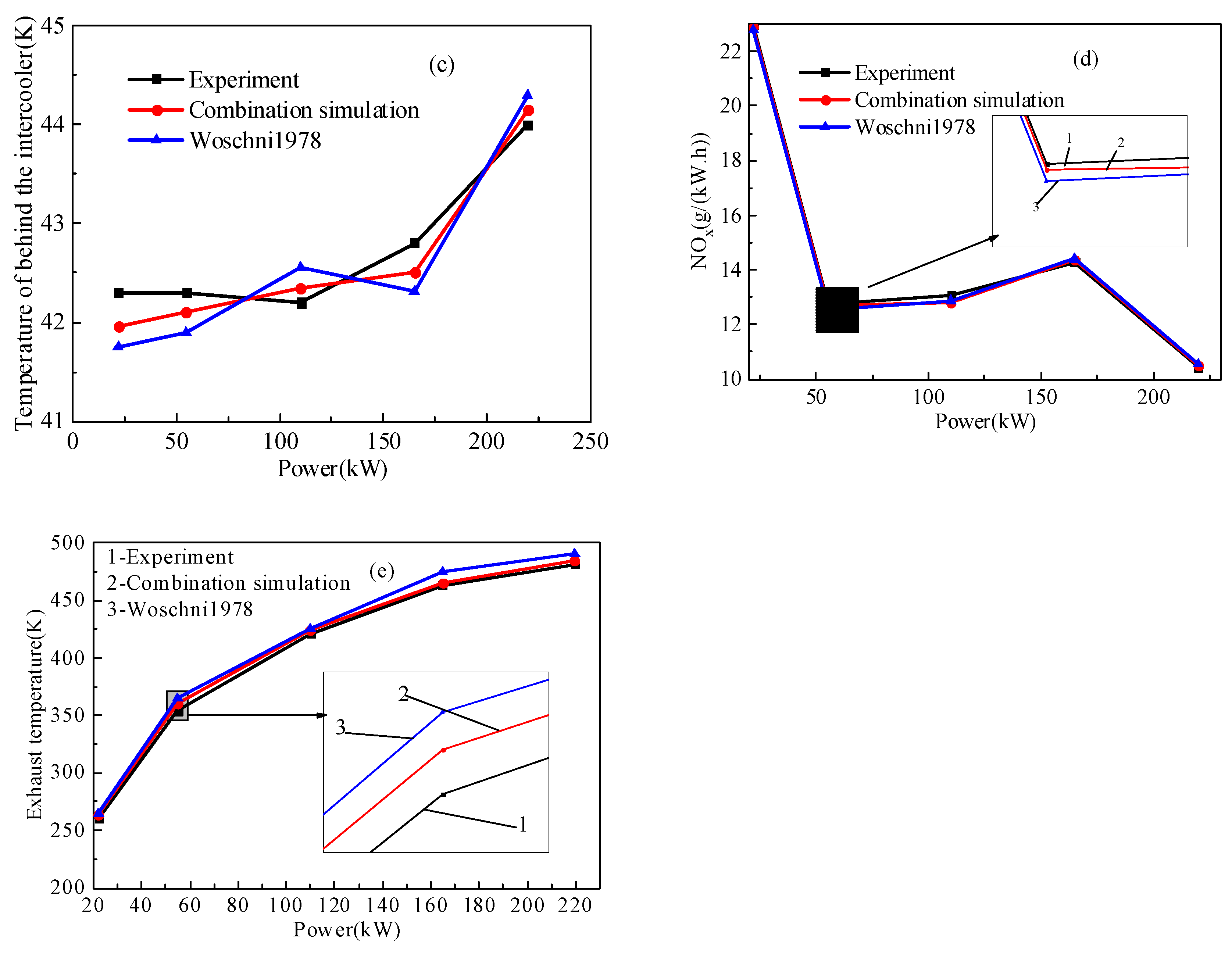
3.1. Load Characteristic of Diesel Engine

The improved heat transfer model and Woschni 1978 model were used to investigate the load characteristic of a diesel engine fueled with RME. The load characteristic is discussed in the part in terms of torque, BSFC, temperature behind the intercooler, NOx, and exhaust temperature. The simulation results of torque, BFSC, temperature behind the intercooler, NOx, and exhaust temperature are compared with experimental data as shown in Figure 4.
Figure 4a shows that torque and power are proportional with the same factor and all the points are on the same line. In addition, torque increased with the increase of power. The results also show that the torque can be calculated accurately by numerical modes. More specifically, the maximum different between experimental result and predicted result calculated by the Woschni1978 model is 4.8% and the maximum difference between the experimental result and predicted result calculated by the improved model reached 3.6%. Thus, the improved combination model could better predict the torque of the diesel engine. Figure 4b shows that the BSFC firstly decreases and then increases with the increase of power. In addition, the BSFC reaches the minimum value at 75% engine load. As the operating point at 75% engine load is the design operating point, the BSFC reached the minimum value at 75% engine load. Actually, the predicted results of the improved model has a better accuracy when compared with the Woschni 1978 model. More specifically, the calculated BSFC is very similar and the maximum difference between the experiment and improved model is 2.8%. In addition, the maximum difference between the experiment and Woschni 1978 model is 3.5%. Thus, the BSFC can be better predicted by the improved combination model.
In addition, Figure 4c shows that the temperature of behind the inter-cooler increases with the increase of the engine power. More specifically, the maximum difference between the experimental result and predicted result calculated by the Woschni1978 model is 3.8% and the maximum difference between the experimental result and predicted result calculated by the improved model reached 2.6%. Figure 4d shows that the NOx emission firstly decreases, increases, and finally decreases with the increased engine power. The NOx emission increases with the increasing power, but the increase of power is slower than the NOx emission. Thus, the NOx emission per unit power increases. When the load is higher than 75%, the NOx emission deceases. It is due to the fact that the combustion is deteriorated by the increase of fuel. In addition, it can also be found that the improved combination model can better predict NOx emission. Figure 4e shows that the exhaust temperature increases with the increase of the engine power. This is due to the increased engine load caused by the increased of fuel injection mass. It can also be found that the improved model can better computed the temperature. More specifically, the maximum difference between the experiment and the improved model is slightly lower than the maximum difference between the experiment and Woschni 1978 model.
As mentioned, the Woschni 1978 model and improved model can also better predicted the load characteristic of diesel engine. However, the improved model is more accurate in prediction. It is due to the fact that the improved model combines the advantages of the two models.

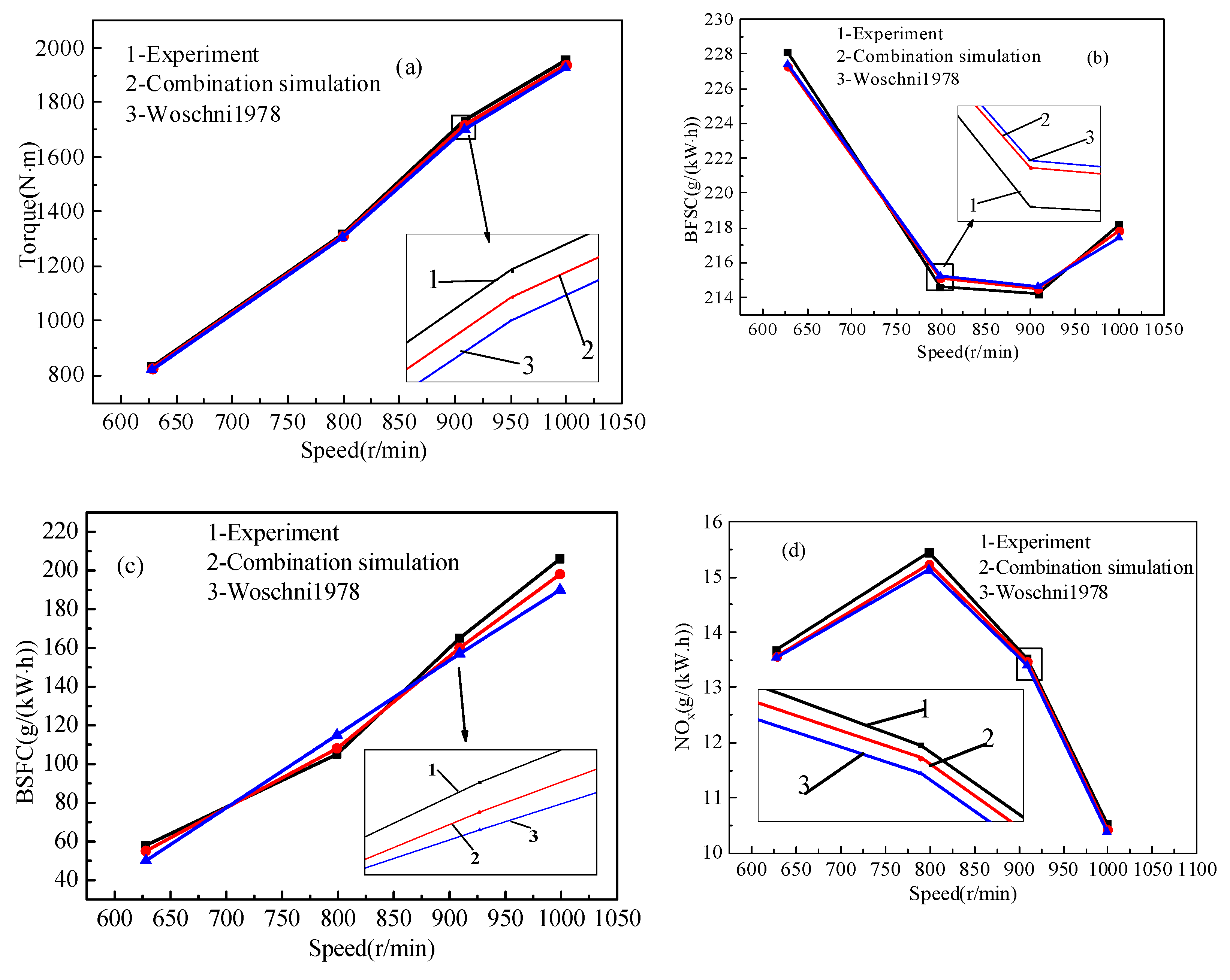
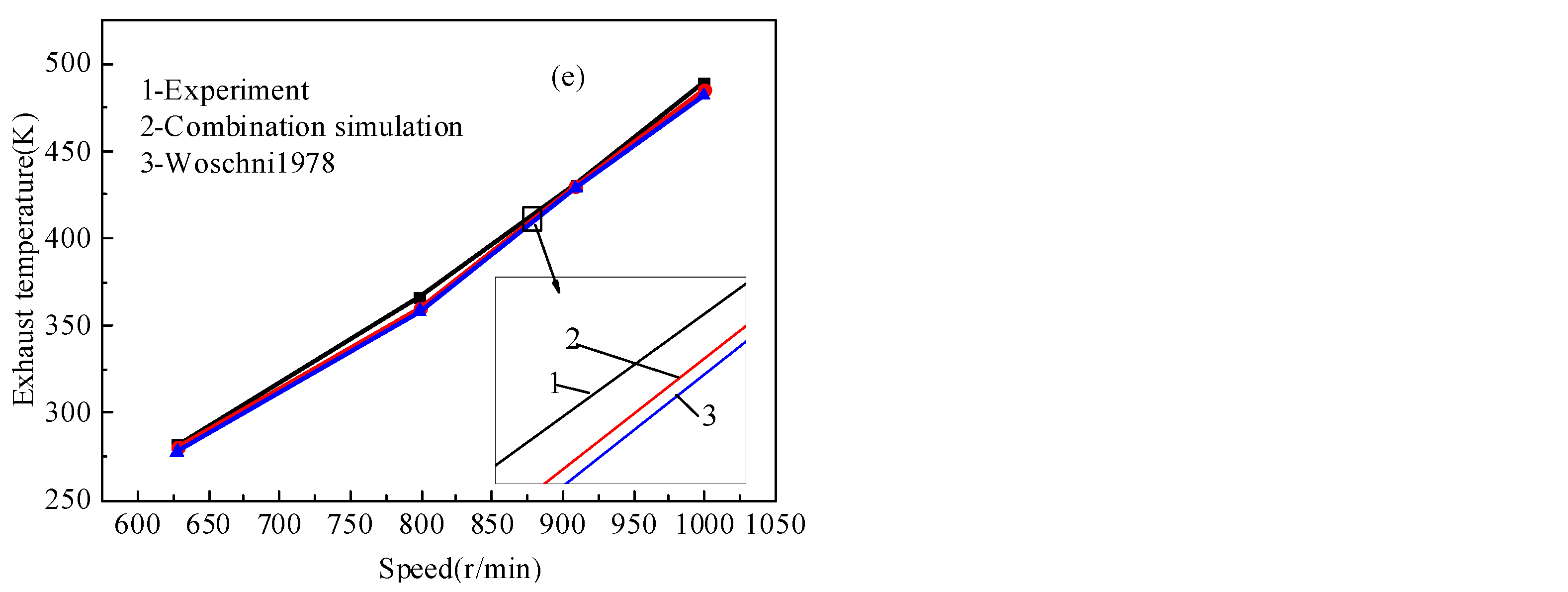
3.2. Propulsion Characteristic of Diesel Engine

In order to further study the propulsion characteristics of electronically-controlled diesel engine, the improved heat transfer model and Woschni 1978 model are employed to investigate the propulsion characteristic of the diesel engine fuel with RME. The diesel engine was operated at different engine loads of 25%, 50%, 75%, and 100%, corresponding to 628 rpm, 799 rpm, 909 rpm, and 1000 rpm engine speed. The propulsion characteristic is discussed in part in terms of torque, BSFC, power, NOx, and exhaust temperature. The simulation results of torque, BFSC, temperature behind the intercooler, NOx, and exhaust temperature are compared with experimental results as shown in Figure 5.
Figure 5a shows that the torque increases with the increase of engine speed. The torque can be calculated accurately by the numerical modes. More specifically, the maximum difference between the experimental result and predicted result by the Woschni1978 model is 4.5% and the maximum difference between the experimental result and predicted result by the improved model reached 3.7%. Thus, the improved combination model could better predict the torque of the diesel engine. Figure 5b shows that the BSFC firstly decreases and then increases with the increase of the engine speed. Between 799 rpm and 910 rpm, the BFSC is lower than the other operating points. The BSFC reached the minimum value at 75% engine load. It is due to the fact that the operating point is the design operating point. Therefore, the efficiency is relatively large. In addition, it can also be found that the improved model can better predict the BSFC and the maximum difference between the improved model and experiment is slightly lower than the maximum difference between the experiment and Woschni 1978 model.
In addition, Figure 5c shows that the engine power and exhaust temperature increase with the increase of the engine speed. It is due to the increased engine load caused by the increased of the fuel injection mass. Figure 5d shows that the NOx emission firstly increases and then decreases with the increased engine speed. It is due to the higher cylinder temperature caused by fuel injection mass. When the speed is higher than 799 rpm, the effects of a high cylinder temperature would be dominated by the impact of decreased oxygen content. Thus, the NOx emission per unit power decreases. It can also be found that the improved combination model could better predict the NOx emission. Figure 5e shows that the exhaust temperature increases with the increase of the engine speed due to the increased fuel injection mass. It can also be found that the improved model could better compute temperature. More specifically, the maximum difference between the experiment and improved model is slightly lower than the maximum difference between the experiment and Woschni 1978 model.
As mentioned, the Woschni 1978 model and improved model also can better predicted the propulsion characteristic of the diesel engine. However, the improved model is more accurate in prediction. It is also due to the fact that the advantages of the two models are combined.

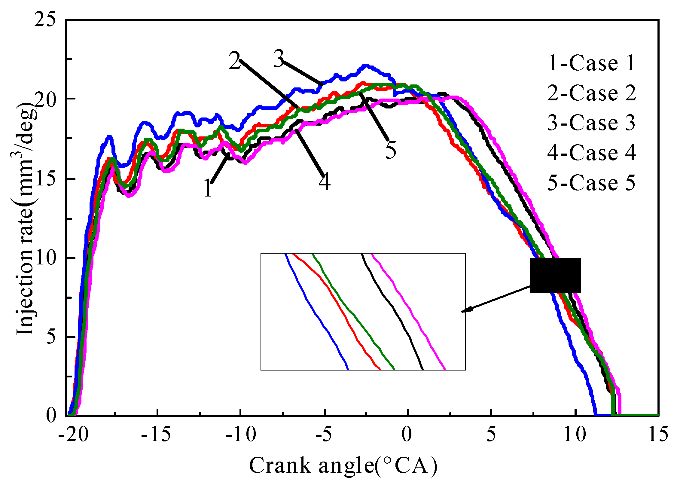
3.3. Fuel Inject Rate

The precise measurement and calibration of the fuel inject rate is essential to an analysis of the formation of mixed gas and combustion processes in an engine cylinder. The main typical parameters, such as injection pressure, fuel mass per cycle, and injection duration, should be considered. In the order to improve the combustion, the high-pressure oil pipe, injector nozzle, plunger diameter, injection duration angle, and injection pressure should be considered in the paper. As for the five cases shown in Table 4, the fuel injection rates are shown in Figure 6. It can be found that the effect of the length of a high-pressure oil pipe on the injection rate is insignificant and the injection pressure decreases with the increase of the length of a high-pressure oil pipe, as shown in Table 4. It is due to the increased resistances caused by the increased length of the high-pressure pipe. In addition, Figure 7 shows that the fuel injection rate and injection pressure increases with the increased diameter of the plunger when the fuel injection mass keeps constant. The injection duration angle decreases with the increased of the plunger’s diameter. With the increased of the injector nozzle diameter, the injection pressure, injection duration angle, and injection rate decrease. The nozzle diameter and diameter of the plunger are significant to the fuel injection rate.

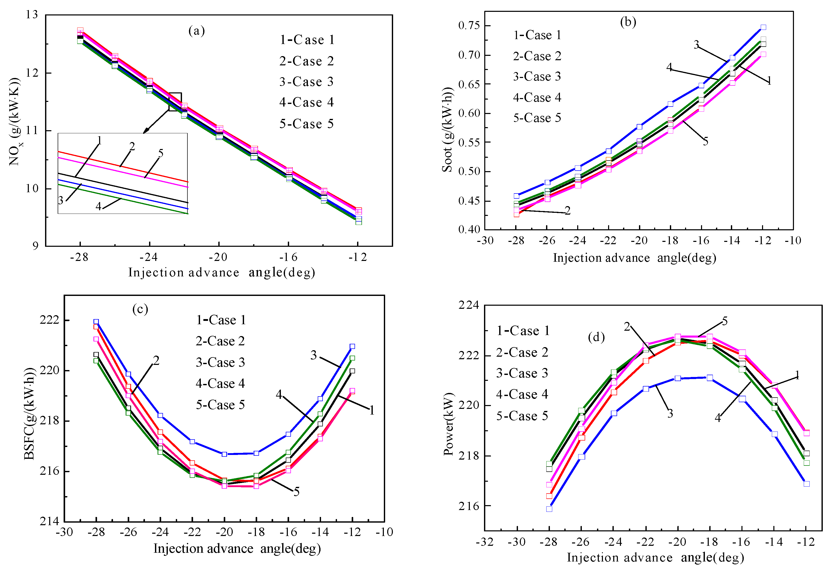
3.3.1. Injection Advance Angle

The injection advance angle is very important. In order to study the effects of an injection advance angle on a diesel engine, five cases are simulated by using the combined heat transfer model at a different injection advance angle, respectively. Figure 7a shows that the NOx increases with the increase of the injection advance angle and Figure 7b shows that the soot emission decreases with the increase of the injection advance angle. When the fuel injection advance angle increases, the combustion duration and in-cylinder temperature increase. Thus, the NOx emission increases. However, the increase of the fuel injection advance angle is favorable for the oxidation of soot. In addition, it can be found that a higher injection pressure can improve the combustion of a diesel engine and reduce the soot emission, but the NOx emission will increase. A large nozzle diameter can reduce the injection duration, but it is not favorable for fuel atomization. Thus, Case 3 has the lowest soot emission.
Figure 7c shows that BSFC firstly decreases and then increases when the injection advance angle reduces. BSFCs is the minimum value when the injection advance angle is −20 °CA. It is due to the fact that lots of negative work is produced when the injection advance angle is more than −20 °CA. The greater the injection advance angle, the more negative work there is. In addition, if the injection advance angle is too small, the fuel cannot burn quickly near the top dead center. Thus, the BSFC also increase. It also can be found that fuel injection pressure and nozzle diameter have great effects on BSFC. A large nozzle diameter and low injection pressure is not favorable for fuel atomization. Thus, Case 3 has the highest BSFC. Figure 7d shows that the power firstly increases and then decreases when the injection advance angle reduces. The different injection advance angle will result in fluctuation of engine power due to the negative work and combustion. The big injection advance angle is beneficial to improving the combustion. Nevertheless, by further increasing the injection advance angle, the improving effect would be dominated by the impact of increased negative work. Thus, the proper injection advance angle is very important.

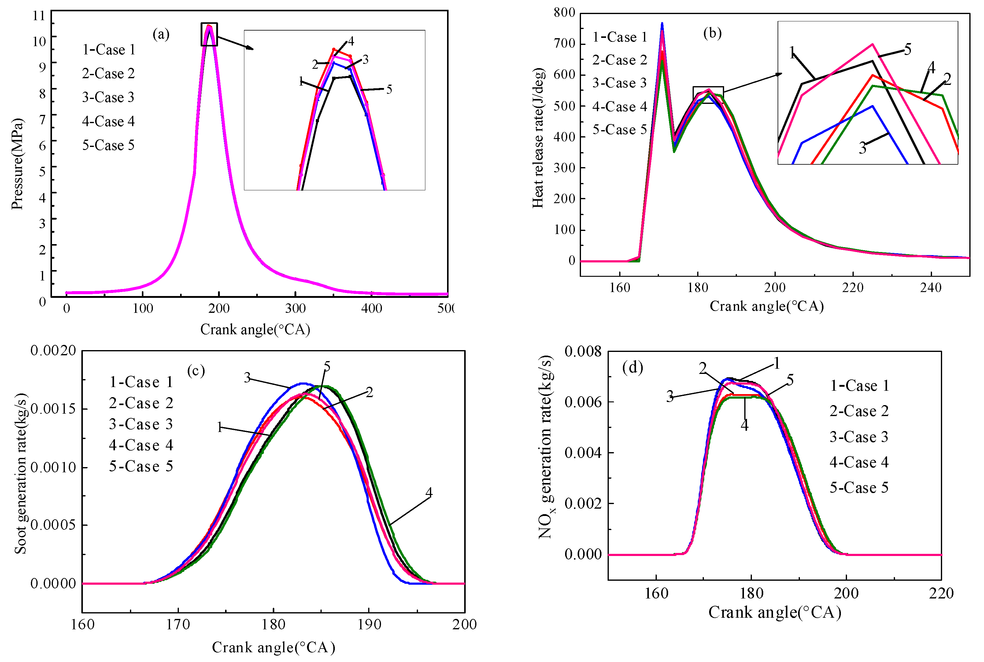
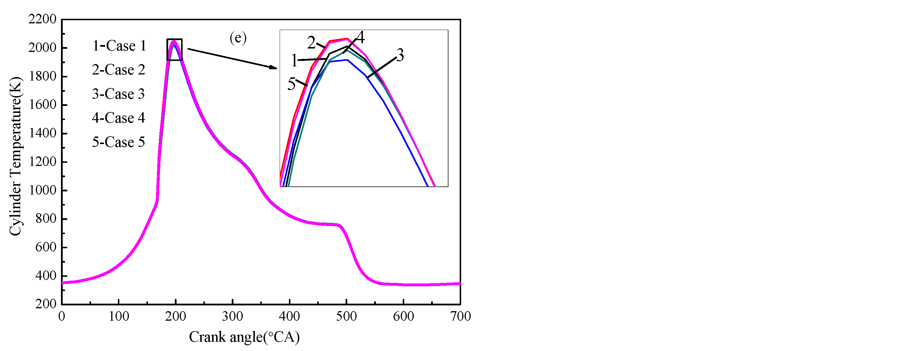
3.3.2. Characteristic Analysis

The improved heat transfer model is used to investigate the effect of a fuel injection rate on a diesel engine fueled with rapeseed oil methyl ester (RME) in terms of cylinder pressure, heat release rate, soot, NOx, and cylinder temperature. In the experiment, the engine speed is at 1000rpm and the fuel injection mass remains constant. The effects of the injection rate on the diesel engine are shown in Figure 8.
As shown in Figure 8a, the cylinder pressure of case 2 is the highest. It is due to the fact that the fuel atomization and cylinder combustion is improved by the high fuel injection pressure. In addition, with the fuel injection pressure delayed, the maximum peak pressure corresponding to the lower, and the time to reach the peak pressure also has a certain delay. As shown in Figure 8b, the fuel injection rate is larger and the heat release rate is larger at an early stage due to the larger injector nozzle diameter. The smaller the fuel injection pressure, the greater the fuel injection map, the longer the delay of heat release rate.
As shown in Figure 8c, the soot generation rate of case 3 is the first to reach the peak. The injector nozzle diameter is larger so that the injection pressure becomes lower. Finally, the fuel atomization becomes worse. Therefore, the soot of case 3 generates the most, followed by case 1 and case 4. As shown in Figure 8d, the NOx generation rate is the minimum in case 4 and the NOx generation rate is the maximum in case 3. The high cylinder temperature is the important parameter, resulting in NOx generation. In the early stage, a large amount of fuel is injected into the cylinder in case 3. In addition, the fuel injection pressure is low so that the fuel atomization is relatively bad. It is easy to form the local high temperature area in case 3. Thus, the NOx generation rate is the maximum in case 3. It can be found that the curve of NOx generation is delayed with the decrease of the fuel injection rate, the NOx generation value in turn reaches the maximum value.
As shown in Figure 8e, due to the high fuel injection pressure and fine atomization, the peak in-cylinder temperature is the highest in case 2, followed by case 5. The faster the fuel pressure is built, the faster the temperature will reach the maximum value. In other words, with the delay of building pressure time, the peak in-cylinder temperature is also delayed. The fuel injection pressure and atomization effect of the fuel have the most efficient influence on the cylinder temperature.
Figure 9 shows comparisons of the simulation and experiment results. It can be found that the error between the experiment’s result and simulation result is less than 2%. Thus, the simulation model can accurately forecast the trend of the engine characteristic.
The BFSC and soot emission are the minimum and the effective power is the maximum in case 5. More specifically, compared with case 4, the NOx emission of case 5 is more than 0.94%, but the soot emission of case 5 decreased by 5% and the BFSC of case 5 decreased by 0.42% in case 5. In addition, it can be found that the economy is worse in case 3. The NOx emission is the least in case 4. The efficiency power and torque are relatively large, and the BFSC and soot emission are the least in case 5. Compared with case 3, the effective power and effective torque of case 5 increased by 1.02% and 1.023% respectively, the soot emission of case 5 decreased by 7.4%, but the nitrogen oxides of case 5 only increased by 1.1%. Based on the overall consideration of various factors, case 5 is the most reasonable. Therefore, it is very important to choose the injection rate reasonably. The big inject nozzle is not beneficial for fuel atomization and more soot is produced.

4. Conclusions

With the development in the energy crisis [43,44,45,46,47,48] and environmental problems [10,49,50,51,52,53,54,55,56,57], the effective control of energy saving and the reduction of emissions in engines is a primary area of focus for scholars. In this work, an improved heat transfer model in a cylinder was developed in the AVL-BOOST environment. The corresponding entirety model was performed by an AVL-BOOST coupled a five–component skeletal chemical mechanism consisting of 475 reactions and 134 species, which was then validated by the experiment under different load conditions. Finally, the propulsion and load characteristics of a diesel engine fueled with biodiesel were simulated by the improved heat transfer model. In addition, the effect of the fuel injection rate on the characteristics of a diesel engine fueled with RME was investigated in term of power, BSFC, soot, and NOx emission. The main conclusions are as follows:
(1)
Compared with the Woschni 1978 model, the improved model was more accurate in prediction. The maximum difference between the experiment and Woschni 1978 model was reduced. It is due to the fact that the advantages of the two models were combined by the improved model;
(2)
The effective torque, exhaust temperature, and the temperature behind the intercooler increased with the increase of engine power. In addition, the torque, power, and exhaust temperature increased with the increase of engine speed;
(3)
The big injection advance angle was beneficial to improving the combustion. Nevertheless, by further increasing the injection advance angle, the improving effect would be dominated by the impact of increased negative work;
(4)
Compared with case 3, the effective power and effective torque of case 5 increased by 1.02% and 1.023% respectively, soot emission decreased by 7.4%, but nitrogen oxides only increased by 1.1% in case 5. Based on an overall consideration of various factors, case 5 is the most reasonable.

Author Contributions

W.Y.: Conceptualization, methodology, resources, project administration, writing—original draft preparation; Z.Z.: software, formal analysis, investigation, writing—review and editing, supervision; B.L.: project administration, writing—review and editing. All authors have read and agreed to the published version of the manuscript.

Funding

This work is supported by the Natural Science Foundation of Guangxi under the research grant 2018GXNSFAA281267 and 2018GXNSFAA294072, the Guangxi Young and middle-aged college Teachers Basic Research Ability Promotion Project under the research grant 2020KY39008.

Data Availability Statement

All data used to support the findings of this study are included within the article.

Conflicts of Interest

The authors declare that they have no conflict of interests regarding the publication of this paper.

References

  1. Zhao, D.; Ji, C.; Li, X.; Li, S. Mitigation of premixed flame-sustained thermoacoustic oscillations using an electrical heater. Int. J. Heat Mass Transf. 2015, 86, 309–318. [Google Scholar] [CrossRef]
  2. E, J.; Liu, G.; Zhang, Z.; Han, D.; Chen, J.; Gong, J.; Yin, Z. Effects of gas leakage, heat loss and clearance volume on cold starting performance of a medium speed diesel engine fueled with biodiesel fuel. Appl. Energy 2019, 243, 321–335. [Google Scholar]
  3. E, J.; Zhao, X.; Liu, G.; Zhang, B.; Zuo, Q.; Wei, K.; Li, H.; Han, D.; Gong, J. Effects analysis on optimal microwave energy consumption in the heating process of composite regeneration for the diesel particulate filter. Appl. Energy 2019, 254, 113736. [Google Scholar] [CrossRef]
  4. Zhang, B.; E, J.; Gong, J.; Yuan, W.; Zhao, X.; Hu, W. Influence of structural and operating factors on performance degradation of the diesel particulate filter based on composite regeneration. Appl. Therm. Eng. 2017, 121, 838–852. [Google Scholar] [CrossRef]
  5. Zhang, Z.; Ye, J.; Tan, D.; Feng, Z.; Luo, J.; Tan, Y.; Huang, Y. The effects of Fe2O3 based DOC and SCR catalyst on the combustion and emission characteristics of a diesel engine fueled with biodiesel. Fuel 2020, 120039. [Google Scholar] [CrossRef]
  6. Wu, G.; Lu, Z.; Xu, X.; Pan, W.; Wu, W.; Li, J.; Ji, C. Numerical investigation of aeroacoustics damping performance of a Helmholtz resonator: Effects of geometry, grazing and bias flow. Aerosp. Sci. Technol. 2019, 86, 191–203. [Google Scholar] [CrossRef]
  7. Li, J.; Yang, W.; An, H.; Zhao, D. Effects of fuel ratio and injection timing on gasoline/biodiesel fueled RCCI engine: A modeling study. Appl. Energy 2015, 155, 59–67. [Google Scholar] [CrossRef]
  8. Wang, B.; Xu, J.; Cao, B.; Zhou, X. A novel multimode hybrid energy storage system and its energy management strategy for electric vehicles. J. Power Sources 2015, 281, 432–443. [Google Scholar] [CrossRef]
  9. Wu, G.; Lu, Z.; Pan, W.; Guan, Y.; Li, S.; Ji, C. Experimental demonstration of mitigating self-excited combustion oscillations using an electrical heater. Appl. Energy 2019, 239, 331–342. [Google Scholar] [CrossRef]
  10. E, J.; Pham, M.; Zhao, D.; Deng, Y.; Le, D.; Zuo, W.; Zhu, H.; Liu, T.; Peng, Q.; Zhang, Z. Effect of different technologies on combustion and emissions of the diesel engine fueled with biodiesel: A review. Renew. Sustain. Energy Rev. 2017, 80, 620–647. [Google Scholar]
  11. Jiang, H.; Wang, Y.; Zhou, J.; Chen, Y.; Zhang, M. Morphology control of manganese-based catalysts for low-temperature selective catalytic reduction of NOx. Mater. Lett. 2018, 233, 250–253. [Google Scholar] [CrossRef]
  12. Liu, M.; Deng, Y.; Zhu, H.; Gong, J. Influence analysis of monolith structure on regeneration temperature in the process of microwave regeneration in the diesel particulate filter. Can. J. Chem. Eng. 2016, 94, 168–174. [Google Scholar]
  13. E, J.; Zhao, X.; Qiu, L.; Zhang, Z.; Han, D.; Deng, Y. Experimental investigation on performance and economy characteristics of a diesel engine with variable nozzle turbocharger and its application in urban bus. Energy Convers. Manag. 2019, 193, 149–161. [Google Scholar] [CrossRef]
  14. Liu, T.; E, J.; Yang, W.; Hui, A.; Cai, H. Development of a skeletal mechanism for biodiesel blend surrogates with varying fatty acid methyl esters proportion. Appl. Energy 2016, 162, 278–288. [Google Scholar] [CrossRef]
  15. Imdadul, H.; Masjuki, H.H.; Kalam, M.A.; Zulkifli, N.; Alabdulkarem, A.; Rashed, M.; Teoh, Y.; How, H. Higher alcohol–biodiesel–diesel blends: An approach for improving the performance, emission, and combustion of a light-duty diesel engine. Energy Convers. Manag. 2016, 111, 174–185. [Google Scholar] [CrossRef]
  16. Xu, H.; Liu, S.; Wang, Y.; Lin, Q.; Chen, Y. Promotional effect of Al2O3 on WO3/CeO2-ZrO2 monolithic catalyst for selective catalytic reduction of nitrogen oxides with ammonia after hydrothermal aging treatment. J. Appl. Surf. Sci. 2018, 427, 656–669. [Google Scholar] [CrossRef]
  17. Zhang, Z.; Chen, J.; Zhao, X.; Zhang, B.; Deng, Y.; Peng, Q.; Yin, Z. Effects of boiling heat transfer on the performance enhancement of a medium speed diesel engine fueled with diesel and rapeseed methyl ester. Appl. Therm. Eng. 2020, 169, 114984. [Google Scholar] [CrossRef]
  18. Lino, P.; Maione, B.; Rizzo, A. Nonlinear modelling and control of a common rail injection system for diesel engines. Appl. Math. Model. 2007, 31, 1770–1784. [Google Scholar] [CrossRef]
  19. Lähde, T.; Rönkkö, T.; Happonen, M.; Söderström, C.; Virtanen, A.; Solla, A.; Kytö, M.; Rothe, D.; Keskinen, J. Effect of Fuel Injection Pressure on a Heavy-Duty Diesel Engine Nonvolatile Particle Emission. Environ. Sci. Technol. 2011, 45, 2504–2509. [Google Scholar] [CrossRef]
  20. Fan, L.; Long, W.; Zhu, Y.; Xue, Y. A characteristic study of electronic in-line pump system for diesel engierated injectors in common rail systems: Results of the simulations and discussion. Energy Convers. Manag. 2012, 54, 122–132. [Google Scholar]
  21. Frosina, E.; Senatore, A.; Buono, D.; Arnone, L. A Critical Analysis on the Lubrication Circuit of a Non-road Diesel Engine by Adopting a 3D and 1D Approaches. Energy Procedia 2015, 81, 794–804. [Google Scholar] [CrossRef] [Green Version]
  22. Fattah, I.R.; Masjuki, H.H.; Kalam, M.; Wakil, M.; Ashraful, A.M.; Shahir, S. Experimental investigation of performance and regulated emissions of a diesel engine with Calophyllum inophyllum biodiesel blends accompanied by oxidation inhibitors. Energy Convers. Manag. 2014, 83, 232–240. [Google Scholar] [CrossRef]
  23. Mosarof, M.; Kalam, M.A.; Masjuki, H.; Ashraful, A.; Rashed, M.; Imdadul, H.; Monirul, I. Implementation of palm biodiesel based on economic aspects, performance, emission, and wear characteristics. Energy Convers. Manag. 2015, 105, 617–629. [Google Scholar] [CrossRef]
  24. Can, Ö. Combustion characteristics, performance and exhaust emissions of a diesel engine fueled with a waste cooking oil biodiesel mixture. Energy Convers. Manag. 2014, 87, 676–686. [Google Scholar] [CrossRef]
  25. Ozsezen, A.N.; Canakci, M.; Turkcan, A.; Sayin, C. Performance and combustion characteristics of a DI diesel engine fueled with waste palm oil and canola oil methyl esters. Fuel 2009, 88, 629–636. [Google Scholar] [CrossRef]
  26. Giakoumis, E.G.; Rakopoulos, D.C.; Rakopoulos, C.D. Combustion noise radiation during dynamic diesel engine operation including effects of various biofuel blends: A review. Renew. Sustain. Energy Rev. 2016, 54, 1099–1113. [Google Scholar] [CrossRef]
  27. Ma, S.; Zheng, Z.; Liu, H.; Zhang, Q.; Yao, M. Experimental investigation of the effects of diesel injection strategy on gasoline/diesel dual-fuel combustion. Appl. Energy 2013, 109, 202–212. [Google Scholar] [CrossRef]
  28. Boretti, A.A. Numerical evaluation of the performance of a compression ignition CNG engine for heavy duty trucks with an optimum speed power turbine. Int. J. Eng. Technol. Innov. 2011, 1, 12–26. [Google Scholar]
  29. Semin, R.B.; Ismail, R. Investigation of diesel engine performance based on simulation. Am. J. Appl. Sci. 2008, 5, 610–617. [Google Scholar]
  30. Özener, O.; Yüksek, L.; Ergenç, A.T.; Özkan, M. Effects of soybean biodiesel on a DI diesel engine performance, emission and combustion characteristics. Fuel 2014, 115, 875–883. [Google Scholar] [CrossRef]
  31. Nikzadfar, K.; Shamekhi, A.H. Investigating the relative contribution of operational parameters on performance and emissions of a common-rail diesel engine using neural network. Fuel 2014, 125, 116–128. [Google Scholar] [CrossRef]
  32. Mikalsen, R.; Roskilly, A.P. Coupled dynamic–multidimensional modelling of free-piston engine combustion. Appl. Energy 2009, 86, 89–95. [Google Scholar] [CrossRef] [Green Version]
  33. Ismail, H.M.; Ng, H.K.; Gan, S.; Lucchini, T.; Onorati, A. Development of a reduced biodiesel combustion kinetics mechanism for CFD modelling of a light-duty diesel engine. Fuel 2013, 106, 388–400. [Google Scholar] [CrossRef]
  34. Lešnik, L.; Iljaž, J.; Hribernik, A.; Kegl, B. Numerical and experimental study of combustion, performance and emission characteristics of a heavy-duty DI diesel engine running on diesel, biodiesel and their blends. Energy Convers. Manag. 2014, 81, 534–546. [Google Scholar] [CrossRef]
  35. Albrecht, A.; Knop, V.; Corde, G.; Simonet, L.; Castagné, M. Observer Design for Downsized Gasoline Engine Control Using 1D Engine Simulation. Oil Gas Sci. Technol. 2006, 61, 165–179. [Google Scholar]
  36. Muralidharan, K.; Vasudevan, D. Performance, emission and combustion characteristics of a variable compression ratio engine using methyl esters of waste cooking oil and diesel blends. Appl. Energy 2011, 88, 3959–3968. [Google Scholar] [CrossRef]
  37. Yang, Z.; Wang, B.; Wang, Y. Life cycle assessment of fuel cell, electric and internal combustion engine vehicles under different fuel scenarios and driving mileages in China. Energy 2020, 198, 117365. [Google Scholar] [CrossRef]
  38. He, L.; Zhang, S.; Hu, J.; Li, Z.; Zheng, X.; Cao, Y.; Xu, G.; Yan, M.; Wu, Y. On-road emission measurements of reactive nitrogen compounds from heavy-duty diesel trucks in China. Environ. Pollut. 2020, 262, 114280. [Google Scholar] [CrossRef] [PubMed]
  39. Kim, Y.; Raza, H.; Lee, S.; Kim, H. Study on the thermal decomposition rate of ammonium carbamate for a diesel NOx reducing agent-generating system. Fuel 2020, 267, 117306. [Google Scholar] [CrossRef]
  40. Zhang, Z.; E, J.; Deng, Y.; Pham, M.; Zuo, W.; Peng, Q.; Yin, Z. Effects of fatty acid methyl esters proportion on combustion and emission characteristics of a biodiesel fueled marine diesel engine. Energy Convers. Manag. 2018, 159, 244–253. [Google Scholar] [CrossRef]
  41. Liu, T.; E, J.; Yang, W.; Deng, Y.; An, H.; Zhang, Z.; Pham, M. Investigation on the applicability for reaction rates adjustment of the optimized biodiesel skeletal mechanism. Energy 2018, 150, 1031–1038. [Google Scholar] [CrossRef]
  42. E, J.; Zhang, Z.; Chen, J.; Pham, M.; Zhao, X.; Peng, Q.; Zuo, W.; Yin, Z. Performance and emission evaluation of a marine diesel engine fueled by water biodiesel-diesel emulsion blends with a fuel additive of a cerium oxide nanoparticle. Energy Convers. Manag. 2018, 169, 194–205. [Google Scholar] [CrossRef]
  43. Wei, K.; Yang, Y.; Hong, Y.; Zhong, D. A review on ice detection technology and ice elimination technology for wind turbine. Wind Energy 2019, 23, 433–457. [Google Scholar] [CrossRef]
  44. Zuo, H.; Liu, G.; E, J.; Zuo, W.; Wei, K.; Hu, W.; Tan, J.; Zhong, D. Catastrophic analysis on the stability of a large dish solar thermal power generation system with wind-induced vibration. Sol. Energy 2019, 183, 40–49. [Google Scholar] [CrossRef]
  45. Zhang, F.; Liao, G.; E, J.; Chen, J.; Leng, E. Comparative study on the thermodynamic and economic performance of novel absorption power cycles driven by the waste heat from a supercritical CO2 cycle. Energy Convers. Manag. 2021, 228, 113671. [Google Scholar] [CrossRef]
  46. Peng, Q.; Yang, W.; E, J.; Li, Z.; Xu, H.; Fu, G.; Li, S. Investigation on H2/air combustion with C3H8 addition in the combustor with part/full porous medium. Energy Convers. Manag. 2020, 228, 113652. [Google Scholar] [CrossRef]
  47. Zuo, H.; Tan, J.; Wei, K.; Huang, Z.; Zhong, D.; Xie, F. Effects of different poses and wind speeds on wind-induced vibration characteristics of a dish solar concentrator system. Renewable Energy 2021, 167. [Google Scholar] [CrossRef]
  48. Zhang, Z.; E, J.; Chen, J.; Zhu, H.; Zhao, X.; Han, D.; Zuo, W.; Peng, Q.; Gong, J.; Yin, Z. Effects of low-level water addition on spray, combustion and emission characteristics of a medium speed diesel engine fueled with biodiesel fuel. Fuel 2019, 239, 245–262. [Google Scholar] [CrossRef]
  49. Wu, G.; Wu, D.; Li, Y.; Meng, L. Effect of Acetone-n-Butanol-Ethanol (ABE) as an Oxygenate on Combustion, Performance, and Emission Characteristics of a Spark Ignition Engine. J. Chem. 2020, 2020, 7468651. [Google Scholar] [CrossRef] [Green Version]
  50. Han, D.; E, J.; Deng, Y.; Chen, J.; Leng, E.; Liao, G.; Zhao, X.; Feng, C.; Zhang, F. A review of studies using hydrocarbon adsorption material for reducing hydrocarbon emissions from cold start of gasoline engine. Renew. Sustain. Energy Rev. 2021, 135, 110079. [Google Scholar] [CrossRef]
  51. Chu, H.; Ya, Y.; Nie, X.; Qiao, F. Effects of adding cyclohexane, n-hexane, ethanol, and 2,5-dimethylfuran to fuel on soot formation in laminar coflow n-heptane/iso-octane diffusion flame. Combust. Flame 2021, 225, 120–135. [Google Scholar] [CrossRef]
  52. Zhao, X.; E, J.; Liao, G.; Zhang, F.; Chen, J.; Deng, Y. Numerical simulation study on soot continuous regeneration combustion model of diesel particulate filter under exhaust gas heavy load. Fuel 2021, 287, 119795. [Google Scholar] [CrossRef]
  53. E, J.; Zhao, M.; Zuo, Q.; Zhang, B.; Zhang, Z.; Peng, Q.; Han, D.; Zhao, X.; Deng, Y. Effects analysis on diesel soot continuous regeneration performance of a rotary microwave-assisted regeneration diesel particulate filter. Fuel 2020, 260, 116353. [Google Scholar] [CrossRef]
  54. Zhang, B.; Zuo, H.; Huang, Z.; Tan, J.; Zuo, Q. Endpoint forecast of different diesel-biodiesel soot filtration process in diesel particulate filters considering ash deposition. Fuel 2020, 272, 117678. [Google Scholar] [CrossRef]
  55. Wu, G.; Wang, X.; Abubakar, S.; Li, Y.; Liu, Z. A realistic skeletal mechanism for the oxidation of biodiesel surrogate composed of long carbon chain and polyunsaturated compounds. Fuel 2021, 289, 119934. [Google Scholar] [CrossRef]
  56. Xie, Y.; Zuo, Q.; Wang, M.; Wei, K.; Zhang, B.; Chen, W.; Tang, Y.; Wang, Z.; Zhu, G. Effects analysis on soot combustion performance enhancement of an improved catalytic gasoline particulate filter regeneration system with electric heating. Fuel 2021, 290, 119975. [Google Scholar] [CrossRef]
  57. Xie, Y.; Zuo, Q.; Zhu, G.; Guan, Q.; Wei, K.; Zhang, B.; Tang, Y.; Shen, Z. Investigations on the soot combustion performance enhancement of an improved catalytic gasoline particulate filter regeneration system under different electric heating powers. Fuel 2021, 283, 119301. [Google Scholar] [CrossRef]
Figure 1. Simulation model of an entire diesel engine.
Processes 09 00104 g001
Figure 2. Schematics of experimental device.
Processes 09 00104 g002
Figure 3. Heat transfer coefficient.
Processes 09 00104 g003
Figure 4. Load characteristics of an electronically-controlled diesel engine. (a) Torque; (b) BSFC; (c) Temperature of behind the inter-cooler; (d) NOx; (e) Exhaust temperature
Processes 09 00104 g004aProcesses 09 00104 g004b
Figure 5. Propulsion characteristic of an electronically-controlled diesel engine. (a) Torque; (b) BSFC; (c) Temperature of behind the inter-cooler; (d) NOx; (e) Exhaust temperature
Processes 09 00104 g005aProcesses 09 00104 g005b
Figure 6. Fuel injection rate with ca onstant fuel injection mass.
Processes 09 00104 g006
Figure 7. The effects of the injection advance angle on the performance of a diesel engine. (a) NOx; (b) Soot; (c) BSFC; (d) Power.
Processes 09 00104 g007
Figure 8. The effects of the injection rate on a diesel engine. (a) Pressure; (b) Heat release rate; (c) Soot generation rate; (d) NOx generation rate; (e) Cylinder temperature
Processes 09 00104 g008aProcesses 09 00104 g008b
Figure 9. Comparison of the simulation results with constant fuel injection mass. (a) Power; (b) BSCF; (c) NOx; (d) Soot.
Processes 09 00104 g009
Table 1. Main parameters of a diesel engine.
ParameterUnitValue
Cylinder diametermm190
Number of cylinders -4
Rate speedr/min1000
Peak pressureMPa12
Rated powerkW220
Mean effective pressureMPa1.109
Compression ratio-14
Table 2. Main parameters of the fuel injection system (FIS) of the electronic control unit (ECU) pump.
TitleParameterValue
PlungerPlunger diameter (mm)13
Cam profile velocity (mm/CaA)0.46
InjectorOpening pressure (MPa)19
maximum needle lift (mm)0.4
Flow (mL/(30 sec*100 bar))1500
Nozzle number8
Nozzle diameter (mm)0.26
High pressure oil pipeLength (mm)900
internal diameter (mm)2
Solenoid valverod diameter (mm)6.98
maximum rod lift (mm)0.21
Solenoid valve residue air gap (mm)0.12
mass of moving parts (g)14.5
Table 3. Physical properties of fuel.
ItemRapeseed Oil Methyl Ester
Oxygen content(%m/m)10.7
Viscosity at 40 °C (mm·s−2)4.56
Cetane number (−)53.88
Lower calorific value (MJ/kg)39.53
Density at 15 °C (kg·m−3)882
Saturation (%)4.45
Methyl linoleate22.27
Methyl linolenate8.11
Methyl stearate0.87
Methl oleate65.18
Methyl palmitate3.57
Table 4. Work cases.
CasesHigh Pressure Oil Pipe Length/mmInjector Nozzle Diameter/mmPlunger Diameter/mmInjection Duration Angle/°Injection Pressure/MPa
Case 18500.2414.033.4100.944
Case 28500.2414.532.9108.377
Case 38500.2614.532.5100.700
Case 49000.2414.033.6100.604
Case 59000.2414.533.1108.267
Table 5. Test cycle for different test points.
Test CycleItemValue
Load characteristicEngine speed(rpm)1000
Engine Load100%75%50%25%10%
Propulsion characteristicEngine speed(rpm)1000911799628
Engine Load100%75%50%25%
Publisher’s Note: MDPI stays neutral with regard to jurisdictional claims in published maps and institutional affiliations.

