1. Introduction
R-22 is a non-fully halogenated refrigerant that is commonly found in residential refrigeration units and air conditioning (A/C) systems. However, environmental concerns are driving the replacement of R-22 with R-407C or other suitable refrigerants. Fortunately, the vapor pressure of R-407C is the same as that of R-22, so it can be installed in existing systems with no major modifications. R-407C is a zeotropic mixed refrigerant that contains three hydrofluorocarbons (HFCs): difluoromethane (R-32), pentafluoroethane (R-125), and tetrafluoroethane (R-134a) in the proportions by weight of 23%, 25%, and 52%, respectively [
1]. Due to the zeotropic nature of the refrigerant R-407C, a 6 °C temperature glide occurs through any heat transfer process [
2]. This normally increases the thermal efficiency of refrigeration equipment.
The performance of R-407C was investigated experimentally by Devotta et al. [
3] under retrofit conditions to replace the original R-22 in window A/C systems. The results of their study showed a lower cooling capacity, lower coefficient of performance, lower pressure drop, higher power consumption, and higher discharge pressures. Aprea and Greco [
2], Wei et al. [
4], and Jabaraj et al. [
5] reported that R-407C is similar to R-22 with regard to the energy efficiency, temperature of the compressor discharge, pressure, and other performance parameters. Passos et al. [
6] evaluated the overall heat transfer performance for R-407C and R-22 using a test rig with a horizontal, flat micro-fin tube condenser. They determined that the overall heat transfer coefficient (HTC) using R-407C was lower than that of R-22. Imran et al. [
7] and Khalifa et al. [
8] investigated numerically an air cooled condenser with finned tube using R-22 and R-407C. They concluded that the performance of the two refrigerants was comparable.
Various tube configurations, such as pipes with added micro-fins, pipes of varying diameters, and pipes with helical grooves, have been installed in A/C systems to enhance their performance by increasing heat transfer rates. Several authors [
9,
10,
11] have reported experimental investigations of the effects of the shapes of fins and sizes of pipes on pressure loss and heat transferred by condensation when using R-407C. Cavallini et al. [
12] investigated the performance of R-22 and R-407C in micro-finned and smooth tubes, and showed that the addition of micro-fins increased the HTC for similar operating conditions. They found that the HTCs were lower for R-407C than for R-22 but the difference between the respective HTCs decreased with increase in mass flux.
HTCs and corresponding pressure drops in tubes with small diameters carrying R22, R-134a, R-407C and R-410A, have been studied by Wang et al. [
13]. The condensation HTCs have been measured by Eckels and Tesene [
14] for several refrigerants in smooth plain and enhanced pipes. Both studies found that the measured HTCs of R-22, R-134a, and R-410A were not significantly different given the uncertainty of the data. Local heat transfer in smooth horizontal pipes during condensation of R-407C and R-404A has been studied by Boissieux et al. [
15].
The HTCs of condensation for the three refrigerants R-22, R-407C, and R-410A, for horizontal plain, low-fin, and turbo-C tubes were studied experimentally by Jung et al. [
1], who measured the condensation HTCs for the three refrigerants with wall subcooling ranging from 3 °C to 8 °C. They also found the HTCs of refrigerant R-407C to be 24–75% lower for R-22 for the plain and low-fin tube but only 4–5% lower for the turbo-C tube.
Aroonrat and Wongwises [
16,
17,
18] and Aroonrat et al. [
17] performed experimental investigations on the condensation and evaporation of R-134a in dimpled helically coiled and dimpled horizontal tubes with different depths of dimpling. The dimples were to enhance the heat transfer by increasing the flow turbulence. The main observations were that, with respect to smooth tubes, dimpling of the horizontal tube could increase the HTC rate by up to 70% while dimpling of the helical tube increased the HTC by as much as 88%. Tang et al. [
19] experimentally studied the effect on the condensation process of dimpling the outer surface of the inner tube of a co-axial tube-within-a-tube heat exchanger. They demonstrated that condensation was enhanced by approximately 178% for a dimpled inner tube compared to a smooth tube.
Yousef et al. [
20] analyzed the comparative performance of the four refrigerants: R-22, R-134a, R-407C, and R-410A, as alternative cooling fluids in a condenser in a steam power plant. Vijayan and Srinivasan [
21] experimentally investigated the performance of R-22 and R-407C in a window A/C system that was originally charged with R-22 but later charged with R-407C. They found that the coefficient of performance increased, and the power requirement and pressure ratio of the compressor were reduced.
Bohdal et al. [
22] reported an experimental and analytical study into the pressure drop, heat transfer and condensation of three refrigerants R404A, R407C, and R410A flowing through vertical mini- and micro-channels at high-pressure.
Sieres et al. [
23] experimentally investigated optimizing the performance of a R-407C domestic heat pump. The results of this study showed that for liquid-to-water systems the operating mode determines the optimum charge, and that the refrigerant charge has a linear relationship with the refrigerant level in the condenser.
Experimental and numerical investigations were carried out by Wang et al. [
24] to assess the relative thermal performance of trilobal twisted helical coils with different cross-sectional areas. The thermal performance of the trilobal twisted tube was up to 1.31 times higher than that of plain and elliptical tubes. Solanki and Kumar [
25,
26,
27] reported experimental studies of the condensation characteristic in helical coiled heat exchangers. The results revealed that as the quality of the vapor fell so did the pressure drop, which resulted in performance factor reduction. A thorough numerical analysis of the pitch, angle, and coil dimensions carried out on helical tube-in-tube and semicircular heat exchangers was reported by Abu-Hamdeh et al. [
28]. They concluded that the coefficient of performance for coils that were semi-circular in cross-section rather than circular was three times greater than for conventional tube-in-tube arrangements.
Mozafari et al. [
29] experimentally investigated the effect of different inclination angles of helical coiled heat exchangers and found that deceasing the angle of inclination led to an increase in performance factor. Qiu et al. [
30] conducted a numerical study on the effect of the inclination angle on R290 condensation in a mini-channel by evaluating the refrigerant charge, flow, and heat transfer. The results demonstrated that as the angle of inclination increased both HTC and pressure drop due to frictional forces also increased. Lee et al. [
31] performed a numerical study of mini-tube heat exchangers by evaluating film condensation based on thermofluid characteristics. They highlighted that shear stresses over the film surface lead to an increased pressure drop and HTC. The liquid film formed on the wall during the condensation processes caused an increase in velocity.
Some A/C, chilled water systems, and heat pumps use R-407C as the working medium. R-407C and R-22 have very similar operating pressures and performance in dry expansion A/C arrangements. However, conventional systems that operate with R-407C are approximately 25–30% less efficient than systems that use R-22, especially at high ambient temperatures, which is very important in countries such as Kuwait. The size of a condenser could be increased to increase its efficiency. This would be feasible from the perspectives of installation, maintenance, and performance of a system if a helical tube were used; it would also improve the HTCs and require less space. Studies of other refrigerants, such as R-134a, have reported promising findings for the pressure drop and condensation heat transfer in helical pipes. However, to the best of our knowledge, no prior investigations have been conducted regarding the use of the R-407C refrigerant in a helical coiled tube heat exchanger.
In this investigation, local HTCs of R-407C during condensation were measured and recorded for systematic changes in the values of Tsat, coolant temperature, and refrigerant and coolant mass fluxes. How the subcooling temperature impacted on heat transfer performance at the higher value of Tsat of 39 °C in a helical coiled tube was evaluated. The study concentrated on the characteristics of the condensation component of the HTC associated with R-407C in the helicoidal tube.
2. Description of Experimental Test Rig
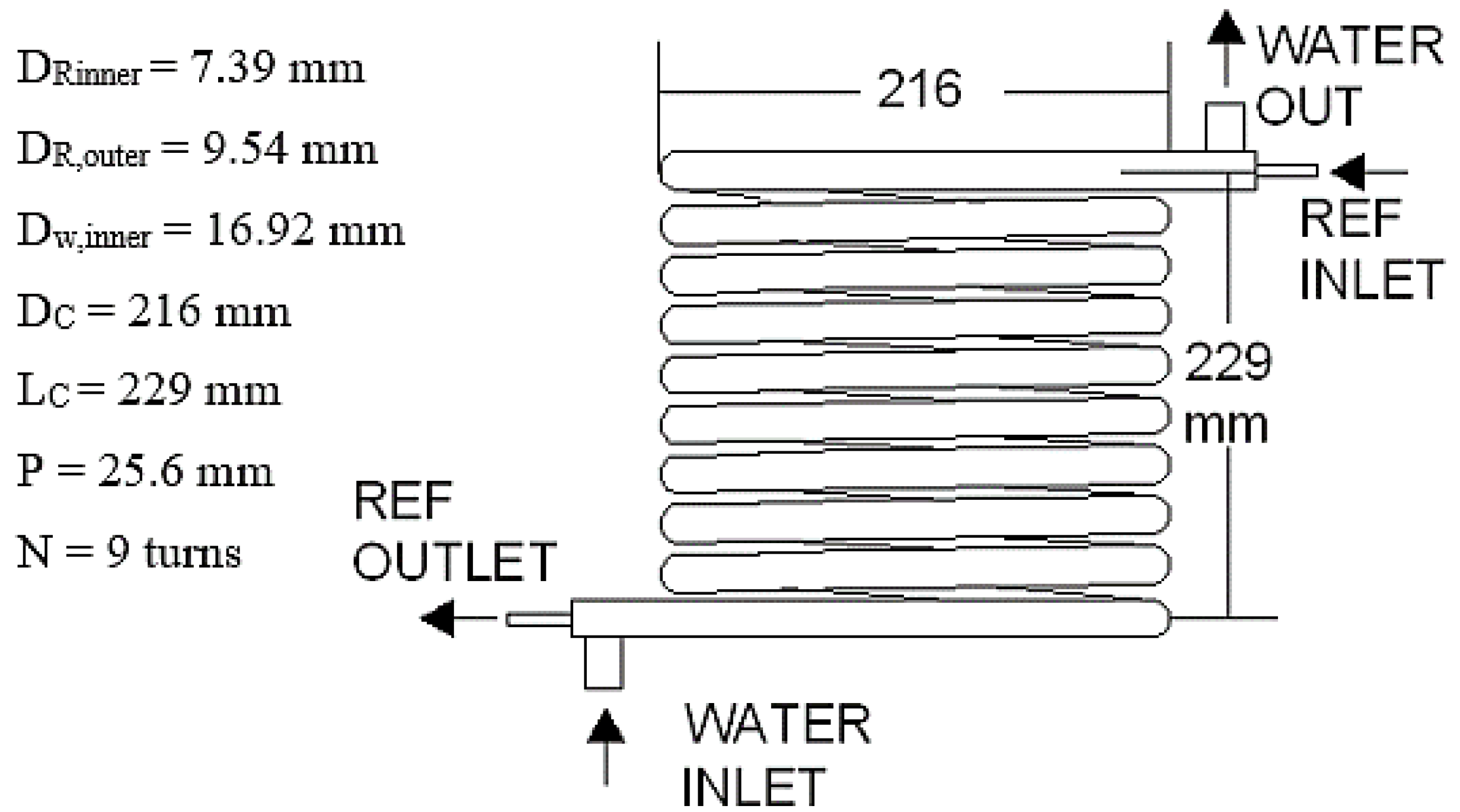
Figure 1 shows the experimental apparatus built to investigate pressure loss and condensation heat transfer for R-407C. The status of the saturated liquid after the reservoir was observed through a small glass window. A flow meter at the entrance to the evaporator was used to measure the R-407C flow rate. The basic arrangement contained a test section, three independent closed cycles, and a data logger. The three cycles are the cooling water, refrigerant, and hot water. The annular helical tube was copper, and its dimensions are shown in
Figure 2.
The experimental apparatus was allowed to reach equilibrium by turning the vacuum pump on for an initial 4 h to make sure that all the refrigerant was evacuated from the loop, and the hot water and cold water loops were filled. This was followed by the injection of R-407C into the refrigerant loop. The temperature of the hot water loop mass flow was set to a suitable value to evaporate the refrigerant in the evaporator. Simultaneously, the cold water loop was set to a value to suitably cool the refrigerant in the condenser heat exchanger. The refrigerant was pumped to the evaporator then it was heated sufficiently to ensure it fully vaporized. After passing over the auxiliary electric heater, the vapor entered the helical tube condenser, where the cold water cooled the refrigerant. Following the helical tube condenser, the refrigerant was cooled to its approximate initial temperature using an air-cooled booster condenser.
Four sight glasses were installed throughout the test section to check the status of the refrigerant.
The helical tube test section was made of double tube copper of coil length 3 m. This was vertically mounted as presented in
Figure 2. The inner tube was the refrigerant side and the outer tube was the waterside. The internal and external diameters of the inner tube were 7.39 mm and 9.54 mm, respectively. The coil section was 216 mm in diameter and 25.6 mm pitch and contained nine turns with a total heat transfer area of 0.18 m
2. The helical tube heat exchanger was counter-flow where the water flowed upward and the refrigerant downward.
4. Data Analysis
The data were analyzed to estimate the condensation HTCs and pressure losses in the helical tube. An energy balance was used to calculate the quality of the refrigerant vapor at the inlet to the condenser, according to the temperature of the water side of the helical tube condenser.
The heat transfer rate (
Q) released from the refrigerant is defined as:
where
Tw,i and
Tw,o are the cooling water temperatures inlet and outlet, respectively,
Cpw is the specific heat of water, and
mw is the mass flow rate of water [
32].
The overall HTC can be expressed as:
where
ΔTLMTD is the logarithmic mean temperature difference for the two fluids used,
Uo is the overall HTC, and
A is the cross-sectional area. The overall HTC is calculated using Equation (3), derived from Equations (1) and (2):
The influence of single-phase heat transfer in the helical pipe can be ignored. Therefore, the
ΔTLMTD is defined by:
where
TR,i and
TR,o are the temperatures of the refrigerant, R-407C, at the inlet and outlet, respectively. The thermal properties of the refrigerants were estimated using the mean value of T
sat and mean pressure in the condenser. The HTC for the refrigerant was estimated by:
where
hw is the heat transfer coefficient for the coolant (water) [
33], and
Rr is thermal resistance for R-407C. The average temperature should be compatible with the cooling water’s thermophysical properties. The mass flux,
mr, and mean heat flux,
q, of R-470 are given by:
where
di,2 is the inner diameter of the inner tube,
L is the length of the helical pipe, and
VR and
ρR are the volumetric flows rate and density respectively of R-407C.
5. Results and Discussion
Three values of Tsat, 31 °C, 35 °C, and 39 °C, were used in the experiment to study how temperature affected the performance of the condenser in an A/C unit containing R-407C. For helical tubes carrying R-407C, the heat transfer rate for the refrigerant depends on flow patterns, pitch, curvature, and void fraction. In this investigation, the helical tube had a fixed pitch and curvature. Experiments were conducted for three different temperatures of the coolant as it entered the condenser. To simplify the study, the wall temperature was maintained at 3 °C, 5 °C, and 7 °C by adjusting the temperature of the coolant for each test.
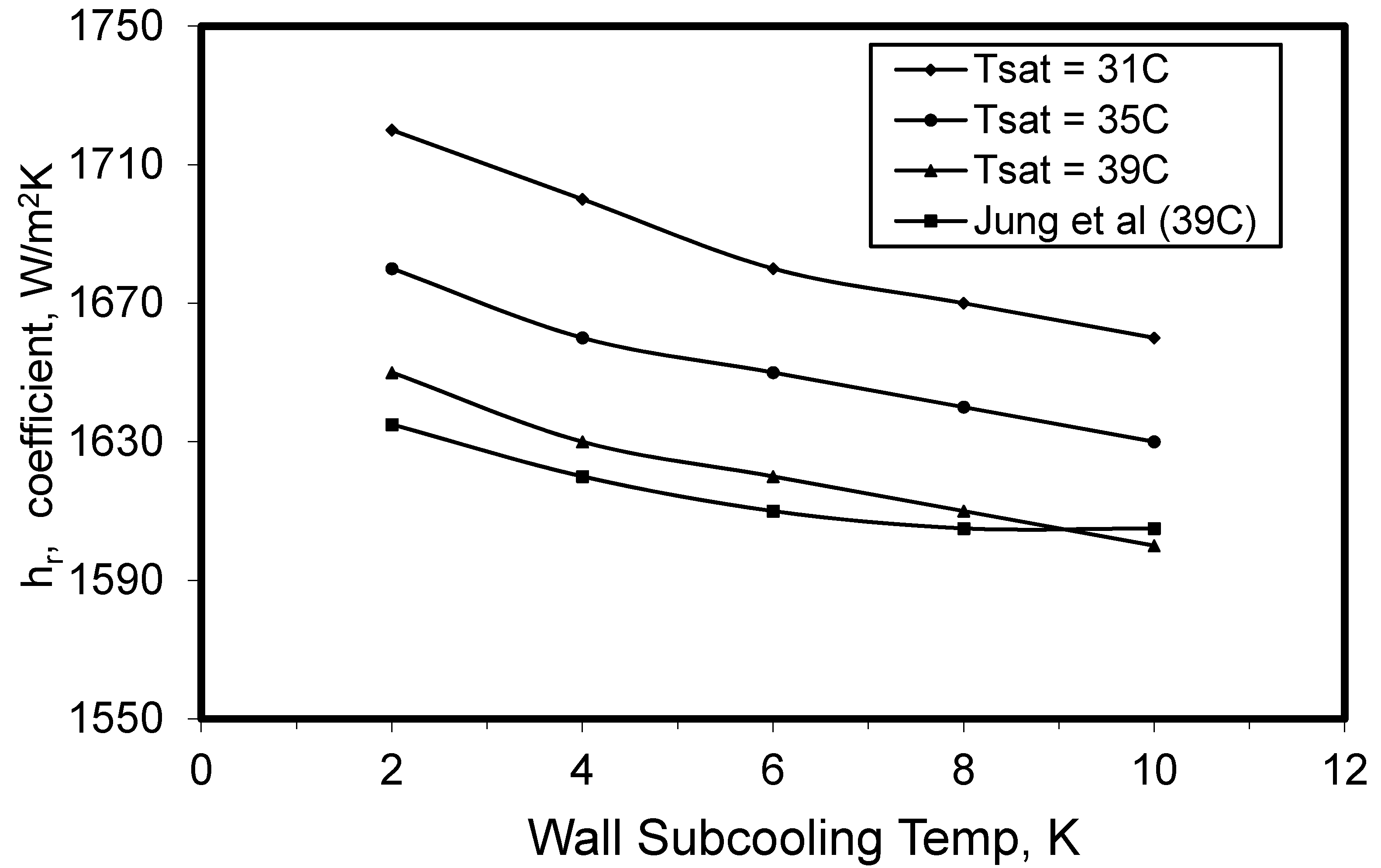
The HTCs for condensation on the refrigerant side as a function of wall subcooling (2–10 °C) for the three values of T
sat; 31 °C, 35 °C, and 39 °C are shown in
Figure 3. Subcooling is defined as the cooling of a liquid refrigerant below the condensing temperature at constant pressure. The wall subcooling temperature is the temperature difference between the refrigerant condensation temperature and the refrigerant temperature at the outlet of the condenser. Increasing the T
sat decreased the HTC, so minimum HTC occurred for the highest value of T
sat (39 °C). In addition, the HTCs decreased as wall subcooling temperatures increased. As the subcooled temperature increased, the temperature difference between the water and refrigerant temperatures decreased causing the HTC to decrease. As a result of the low wall subcooling temperature increases, the refrigerant temperature becomes close to the water cooler temperature. Thus, a lower wall subcooling temperature should be used to improve the performance.
For similar values of Tsat, the HTC determined for a smooth tube was less than that obtained for a helicoidal tube. However, for a high wall subcooling temperature of approximately 10 °C, the HTC for the helical tube showed a slightly lower value compared to the coefficient for the smooth tube. In most practical applications the wall subcooling temperatures used are less than 9 °C, in which case the helical tube will have a higher HTC.
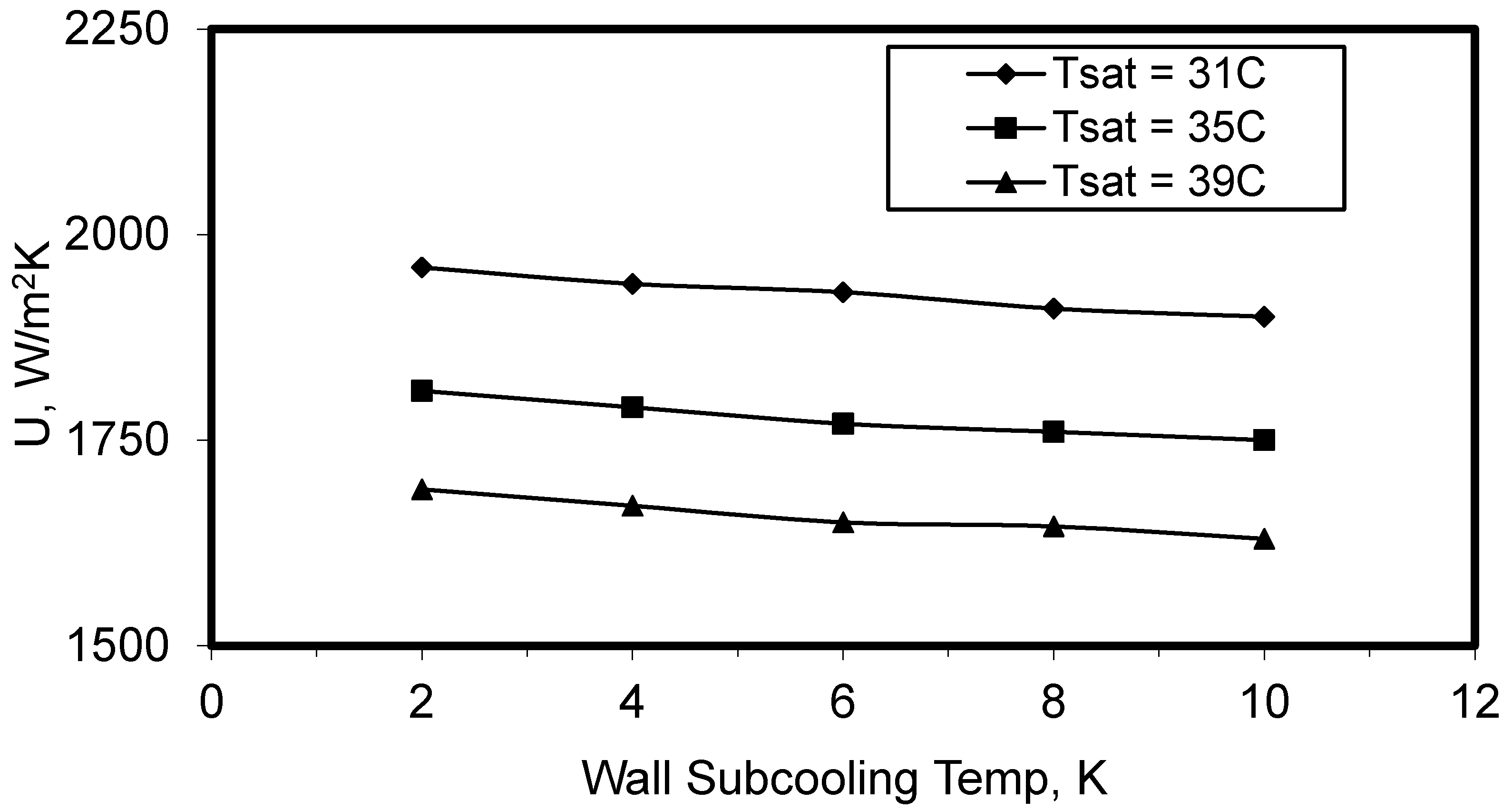
Figure 4 illustrates the overall HTC of R-407C in the helical tube against the subcooling temperature of the wall. For comparison, three values of T
sat were used: 31 °C, 35 °C, and 39 °C. The refrigerant overall HTCs reduced linearly as the wall subcooling temperature increased. Furthermore, these coefficients increased as the value of T
sat decreased. This occurred because of changes in the flow patterns and the reduction in heat transfer to the coolant. Furthermore, when the subcooling temperature increased, the thickness of the condensate layer increased, which decreased the overall HTC.
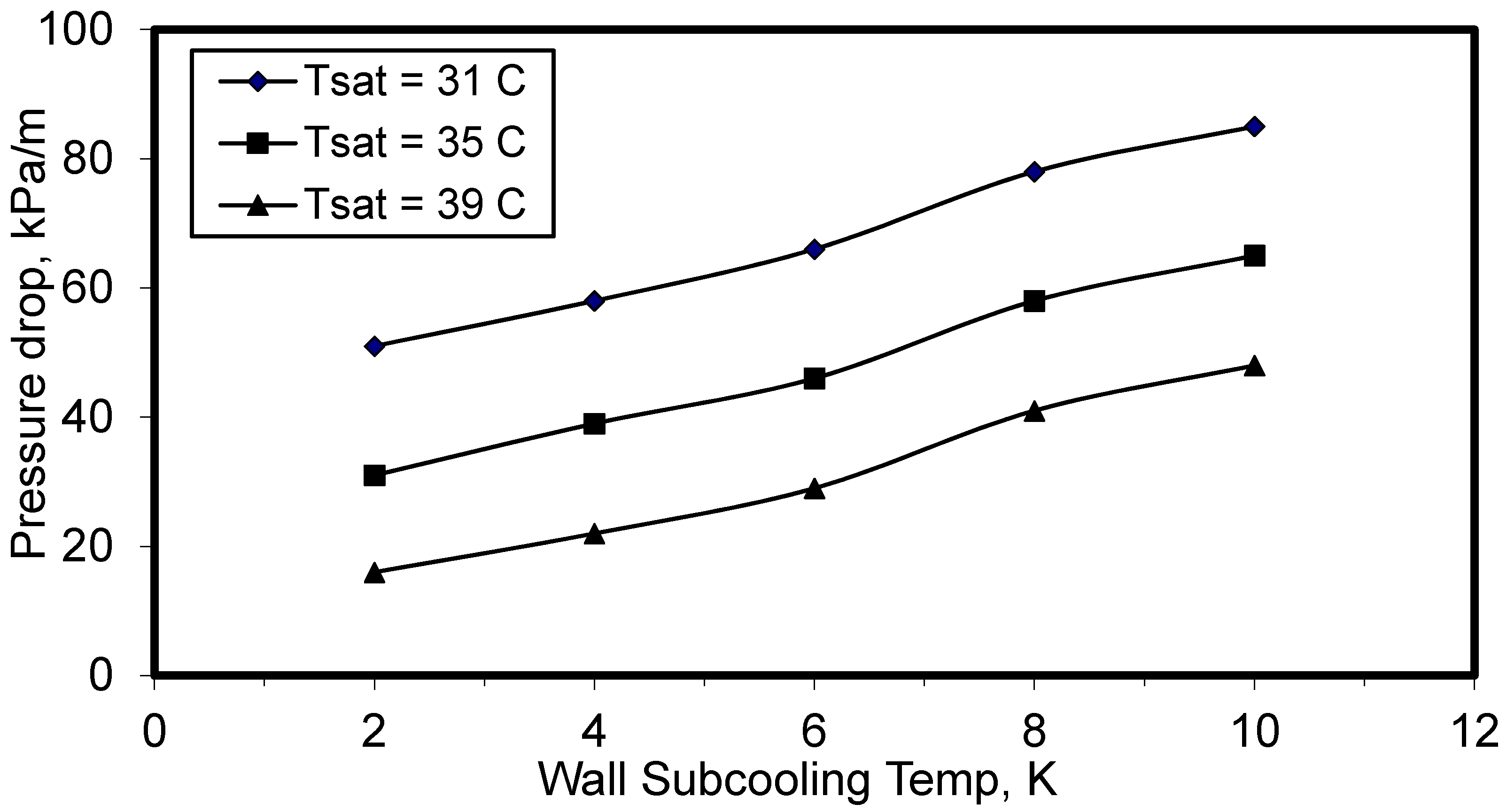
Pressure loss with wall subcooling temperature inside a helicoidal tube is shown in
Figure 5. It was noticed that the pressure loss increased as the wall subcooling temperature increased. As the wall subcooling temperature increased, the refrigerant temperature decreased causing an increase in both density and viscosity generated friction. According to the fundamental laws of fluids, pressure loss has a positive relation with the density. For the three values of T
sat used, the pressure loss increased as T
sat decreased.
Massad et al. [
34] compared the helical tube with other tube geometries and found that the loss in pressure was greater than for straight tubes, due to the greater complexity of the flow patterns in the helical tube. For these different tube arrangements, the same mass flux in the helical tube will contain swirls and a higher turbulence intensity, which results in higher pressure loss.
Alhajeri et al. [
35] compared the pressure drop in a helical tube using R-134a with the pressure drop in a micro-finned straight tube as reported by Eckels and Tesene [
14]. It was concluded that the pressure losses in helicoidal tubes were greater than the loss in micro-finned straight tubes in the case of low refrigerant mass flux.
However, with decreasing refrigerant mass flux, the difference between the pressure losses in the helical tube and the micro-fin straight tube increased, particularly as the temperature of the cooling water increased. If they had used a greater range of mass flux in the study, the drop in pressure in the straight micro-fin tube would have become greater than the decrease in the helical tube because of the loss of pressure produced by the presence of the fins. In the case of a straight tube without fins, as is well known, the pressure loss increases proportional to the length.
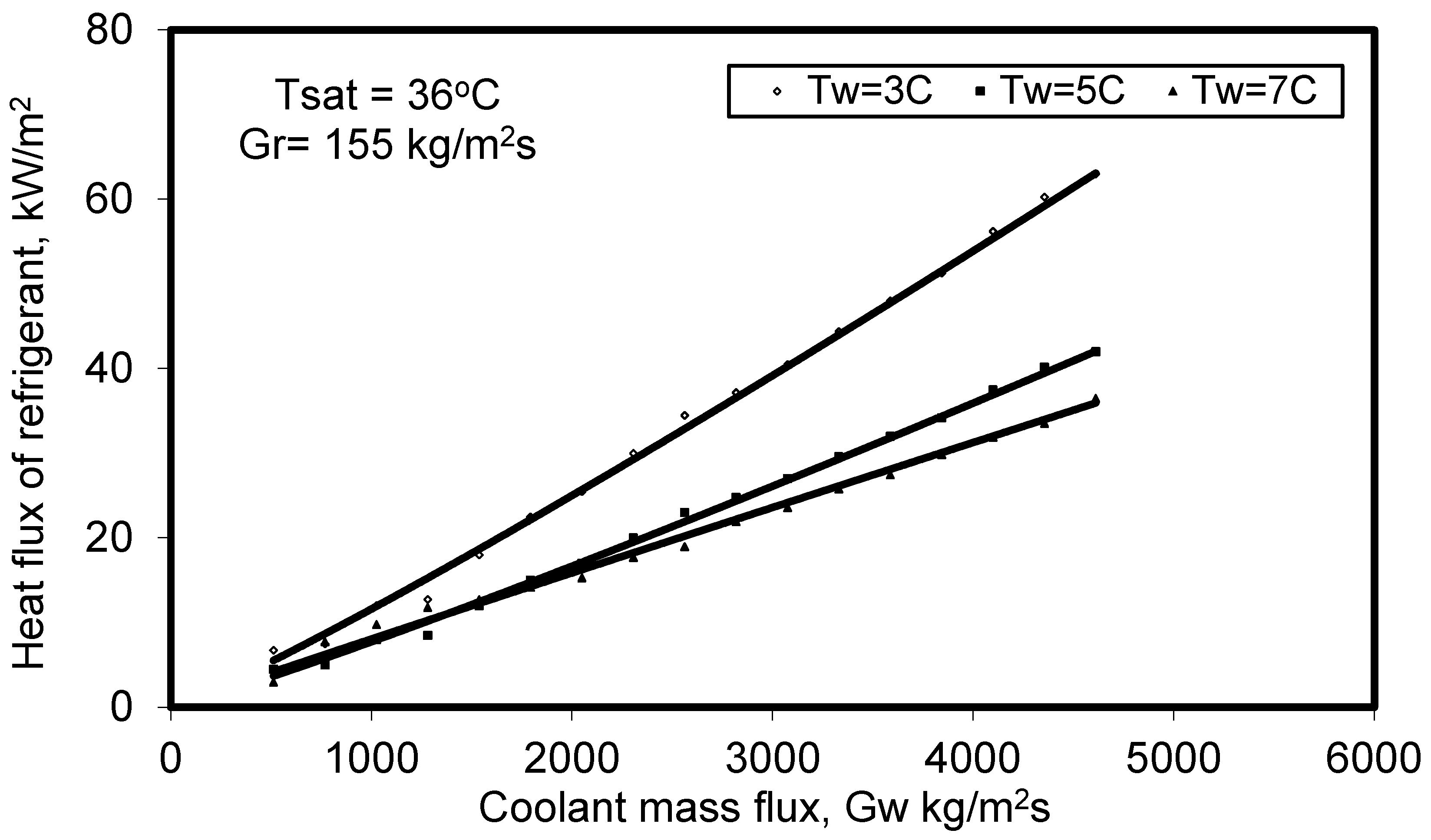
For R-407C,
Figure 6 shows the mean heat flux as a function of coolant water mass flux for the three temperatures 3 °C, 5 °C, and 7 °C. In this figure, two parameters were fixed: the mass flux of the refrigerant was maintained at 155 kg/m
2s and the value of T
sat at 35 °C. The relation indicates that the heat flux of the refrigerant is considerably higher when the wall temperature is lower, and the rate at which the heat flux increases is higher at lower wall temperatures. This is because of the decreases in pressure, viscosity, and density of the refrigerants, which reduce friction, and this allows the refrigerant to have a higher velocity. For low values of the coolant mass flux, about 500 kg/m
2s, the heat fluxes converge to a value of about 5 kW/m
2. The heat flux increases with increase in coolant mass flux and decreases with increase in coolant temperature. Therefore, for enhanced performance it is recommended that a high coolant mass flux is used with low coolant temperature.
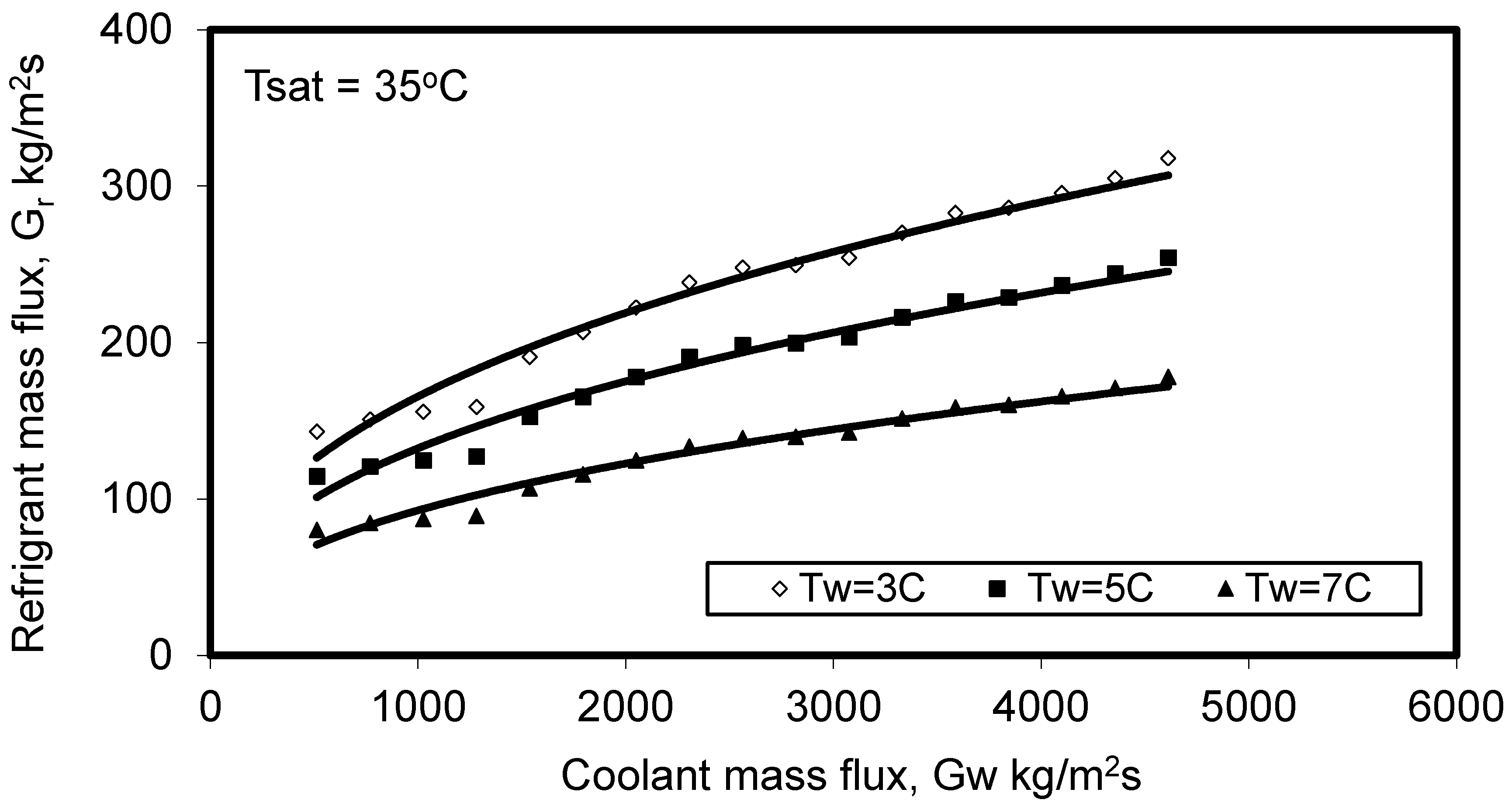
Figure 7 shows how coolant (water) mass flux varies with refrigerant mass flux with T
sat constant at 35 °C. We see that for the three coolant water temperatures, 3 °C, 5 °C, and 7 °C, the refrigerant mass flux increases as the mass flux of the coolant water increases but decreases as the coolant water temperature increases. It follows that A/C systems that use R-407C require low coolant temperatures for optimal operation.
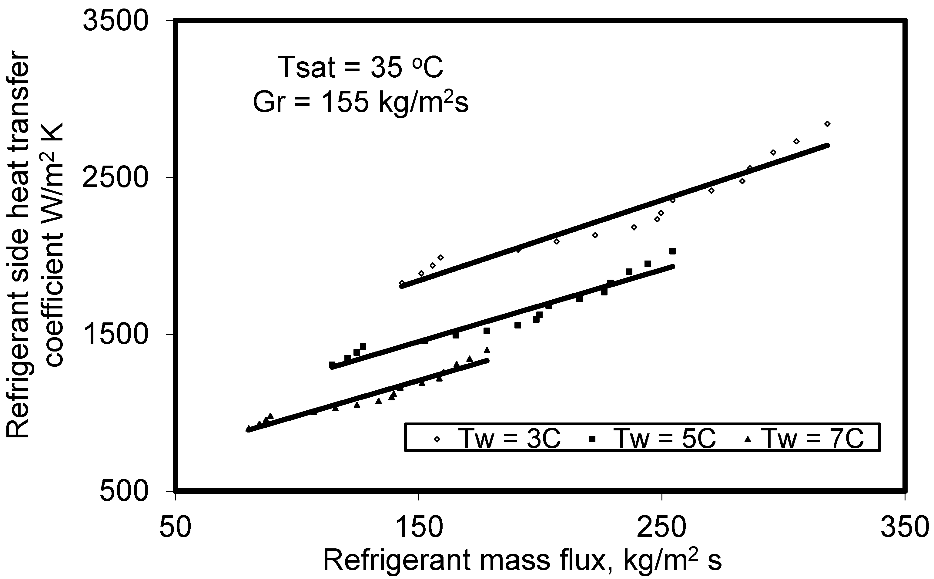
Figure 8 shows the HTC for R-407 as a function of refrigerant mass flux for the three values of Tw: 3 °C, 5 °C, and 7 °C, when using the helical tube heat exchanger. As the refrigerant mass flux increases, the refrigerant HTC also increases. The mass flux in Equation (6) shows that the increase in the velocity of the refrigerant and liquid film causes the mass flux of the refrigerant to increase. This occurred concurrently with the growth of the centrifugal force in the helical pipe which acts on the inner wall increasing the turbulence within the flow of refrigerant and enhancing the heat transfer. Once again, we see that an increase in coolant water temperature reduces the heat transfer, so the use of coolant with a lower temperature increases the temperature difference and improves the refrigerant HTC. With condensation the greater the volume of vapor that condensed, the lower will be the vapor velocity, and the thicker the liquid film, both of which will reduce the average HTC.
The vapor quality of the R-407C refrigerant at condenser inlet and outlet,
xin and
xout, respectively, can be evaluated using Equation (7a,b).
where
hw is the enthalpy of the saturated liquid;
hv is the latent heat of vaporization, measured using the entrance and exit temperatures of the test section;
hR is the enthalpy of the refrigerant; and
i and
o are the entrance and outlet of the condenser.
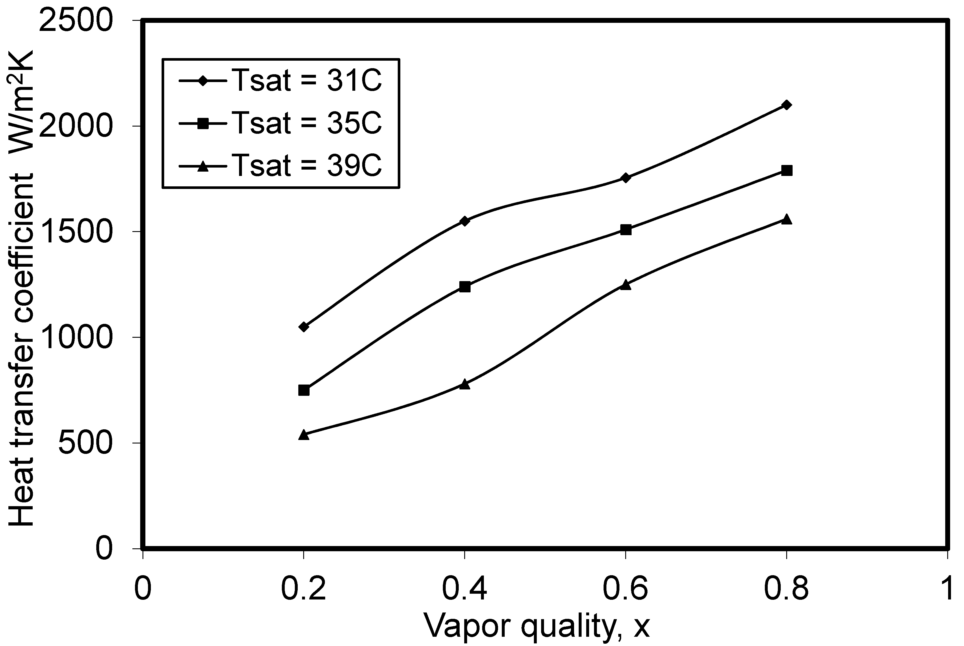
The experimentally measured values of HTC for R-407C as a function of the vapor quality is shown in
Figure 9 for T
sat values of 31 °C, 35 °C, and 39 °C. The vapor quality used in this figure is the arithmetic mean of inlet and outlet qualities. The average HTC increases with increase in vapor quality (lower liquid fraction). This is because the velocity of the refrigerant increased at higher values of vapor quality (more gas phase) at which the shear was increased. Furthermore, secondary flow, turbulence, and HTC were all increased owing to the continuous bend of the helical pipe. The void fraction of the mixture increased when the vapor quality increased, forming a thinner condensate film at the lower part of the pipe and increasing the interfacial area, which reduced the thermal resistance. Consequently, the heat transfer mechanism was more efficient. The HTCs were higher at lower values of T
sat and rose as vapor quality improved.
Uncertainties
The analysis of the uncertainties of the test section of the helical tube for the condensation HTCs was based on Moffat’s work [
36] which also considered the pressure, temperature, water and mass refrigerant flow rates. Referring to the experimental conditions that were used, the uncertainties that were associated with the refrigerant’s mass flow rate, cooling water volume flow rate, cooling water Reynolds number, and temperature differences were 0.25%, 0.34%, 3%, and ±0.4 °C, respectively. In addition, uncertainties in the water side HTCs, refrigerant side HTCs, and overall HTCs were 7%, 21%, and approximately 18%, respectively.
6. Conclusions
The pressure loss and heat transfer coefficient for refrigerant R-407C flowing in a helicoidal copper pipe have been investigated experimentally utilizing a purpose-built test rig. Three saturation vapor temperatures of 31 °C, 35 °C, and 39 °C were used in the study with the temperature of the wall sub-cooling in the range 2–10 °C.
The experimental results showed that as the refrigerant mass flux increased, the heat transfer coefficient increased. As the temperature of the saturated vapor of the refrigerant decreased, both the refrigerant side HTC and the overall HTC increased. The refrigerant pressure loss in the helical tube was found to be dependent on coolant wall temperature and refrigerant, Tsat. It increased with increase in wall subcooling temperature and increased with decrease in Tsat. Thus, as the coolant (water) mass flux increased, the pressure loss in the helical tube decreased.
This investigation has provided information that could be applied to enhance the design of helical coiled tube condensers for A/C and refrigeration applications specially in hot ambient temperature: we recommend the use of a lower wall subcooling temperature, low coolant temperature, high mass flux of coolant, and high mass flux of refrigerant. In addition, using lower temperatures for the water coolant resulted in a higher HTC on the refrigerant side. Furthermore, for higher ambient temperature, a helical coiled tube performs better than a smooth tube through the high HTC to the same Tsat.


 ,
, 


