Continuous Improvement Process in the Development of a Low-Cost Rotational Rheometer


 , , ,
, , ,  ,
,
Abstract
:1. Introduction
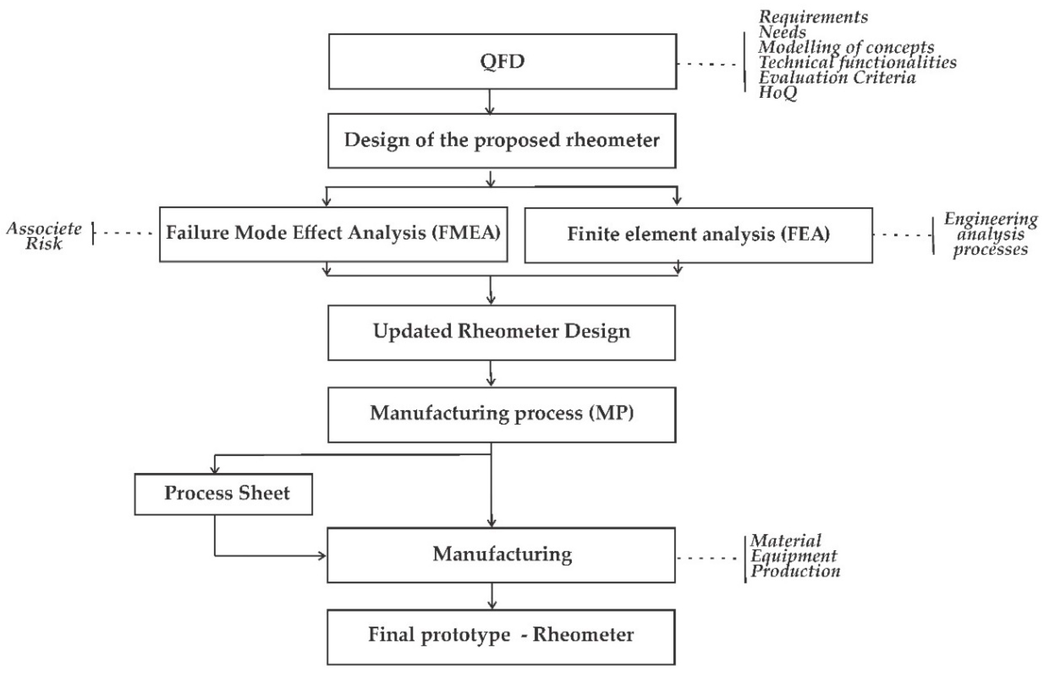
2. Methodology
2.1. Quality Function Deployment (QFD) and House of Quality (HoQ)
2.1.1. Customer Requirements
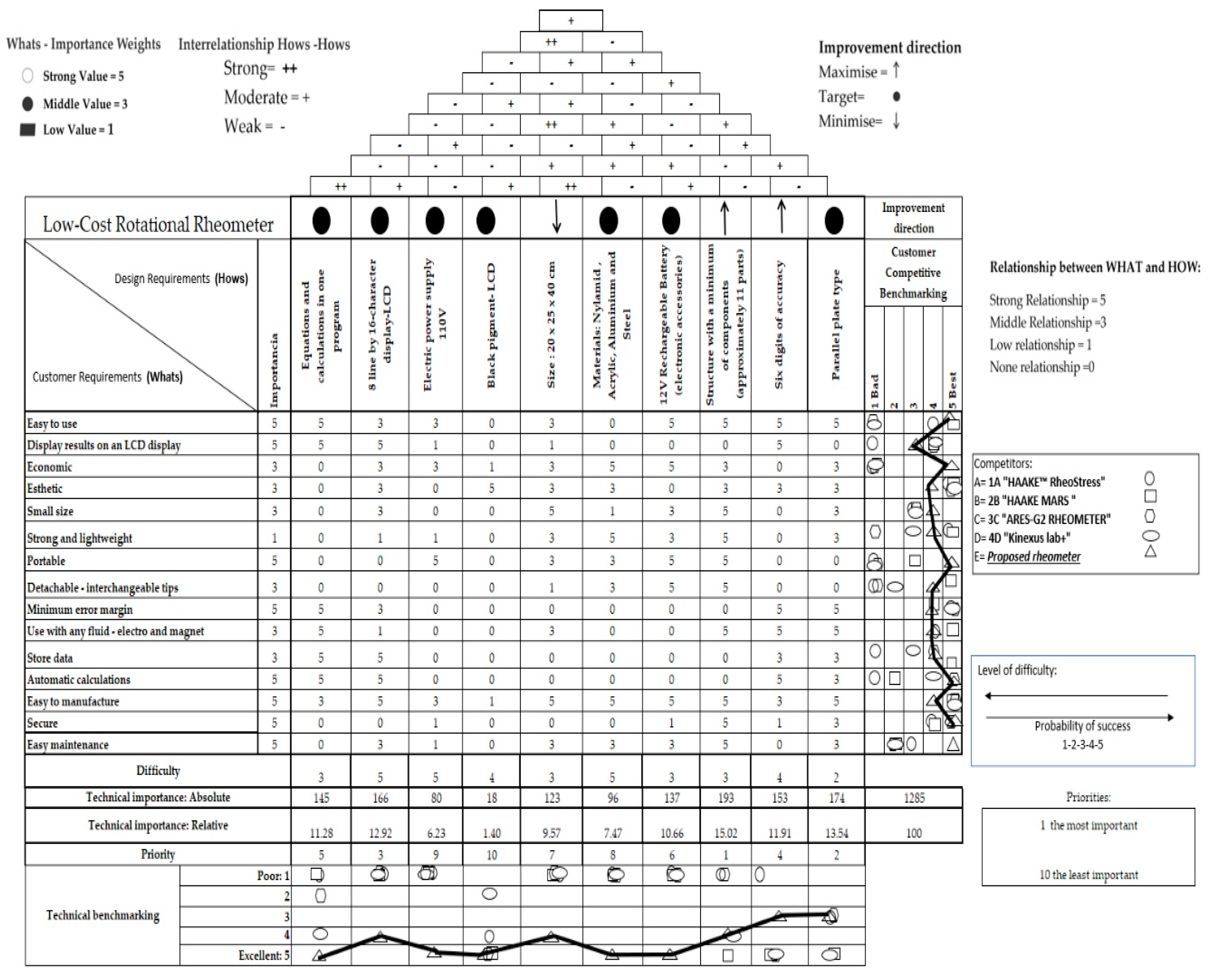
2.1.2. House of Quality (HoQ)
- Document the environment in which the product is used (needs).
- Classify needs in a logical order and evaluate the relative importance therof.
- Understand customer’s needs as summarized in the planning of the product, matrices, or House of Quality.
- Identify the technical requirements directly influencing satisfaction needs in order to formulate complete technical specifications.
2.2. Failure Mode Effect Analysis (FMEA) and Finite Element Analysis (FEA)
2.3. Finite Element Analysis (FEA)
2.4. Manufacturing Process (MP)
Process Sheet
3. Results
3.1. Technical Requirements
3.2. Competitive and Technical Comparison Evaluation (Customer benchmarking-Technical benchmarking)
- (1)
- The technical requirement of minimal parts obtained a high importance index of 193 and a priority order of 1. This means that the proposed design must meet the minimal necessary elements for rheometer operation; this requirement also impacts the ease of maintenance required during its lifecycle.
- (2)
- The technical requirement of parallel plates obtained a high importance index of 174 and a priority order of 2. This technical requirement depends on how the rheological tests are carried out and the condition of the rheometer’s accessories.
- (3)
- The technical requirement for the use of an 8-line display obtained a high importance index of 166 and a priority order of 3. This technical requirement mainly affects how the rheometer user will interact with the variables that must be measured during the rheological tests.
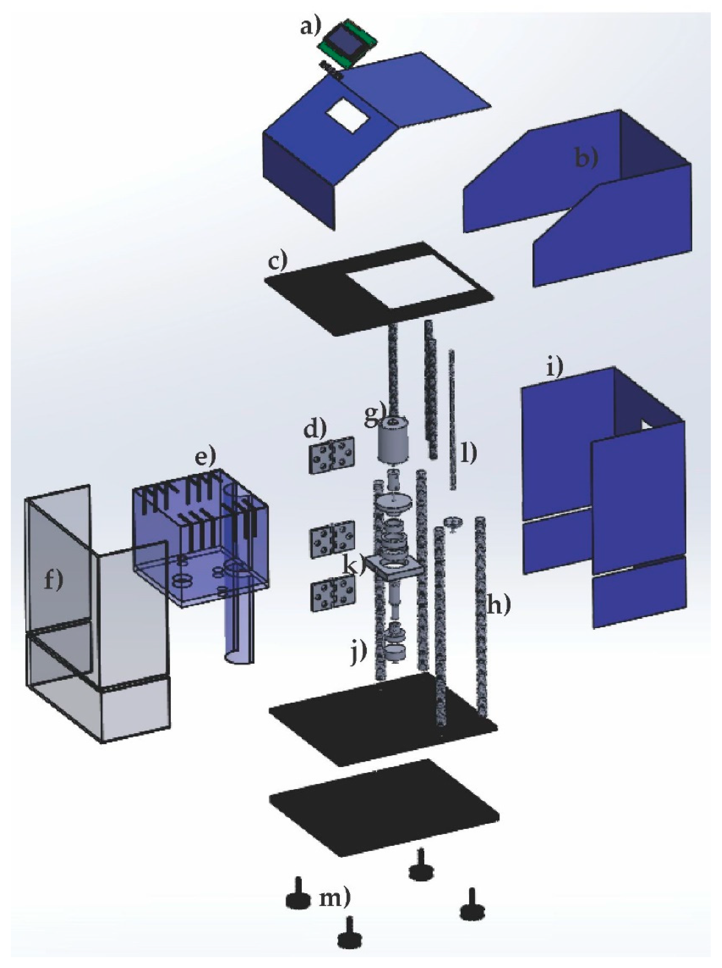
3.3. Preliminary Design
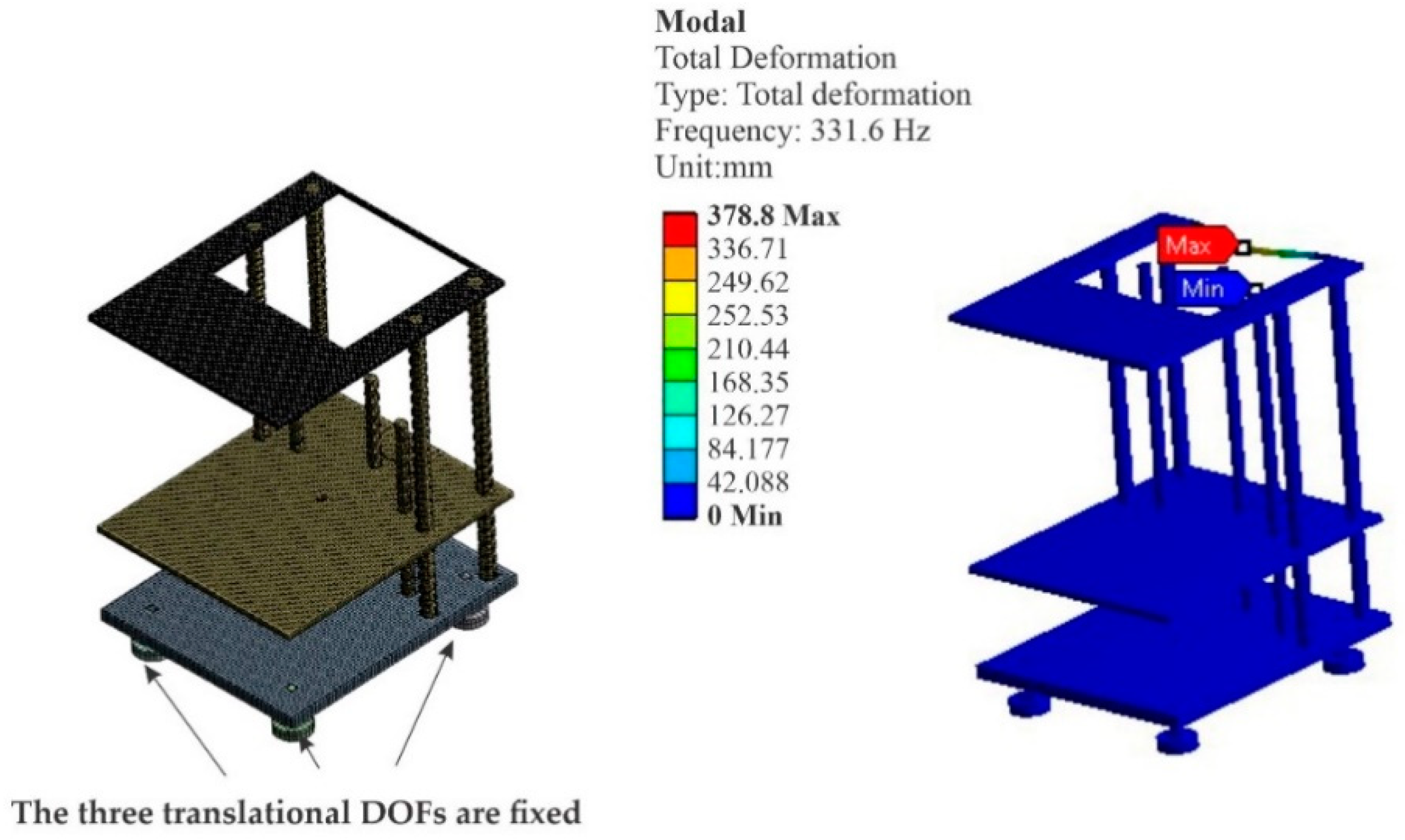
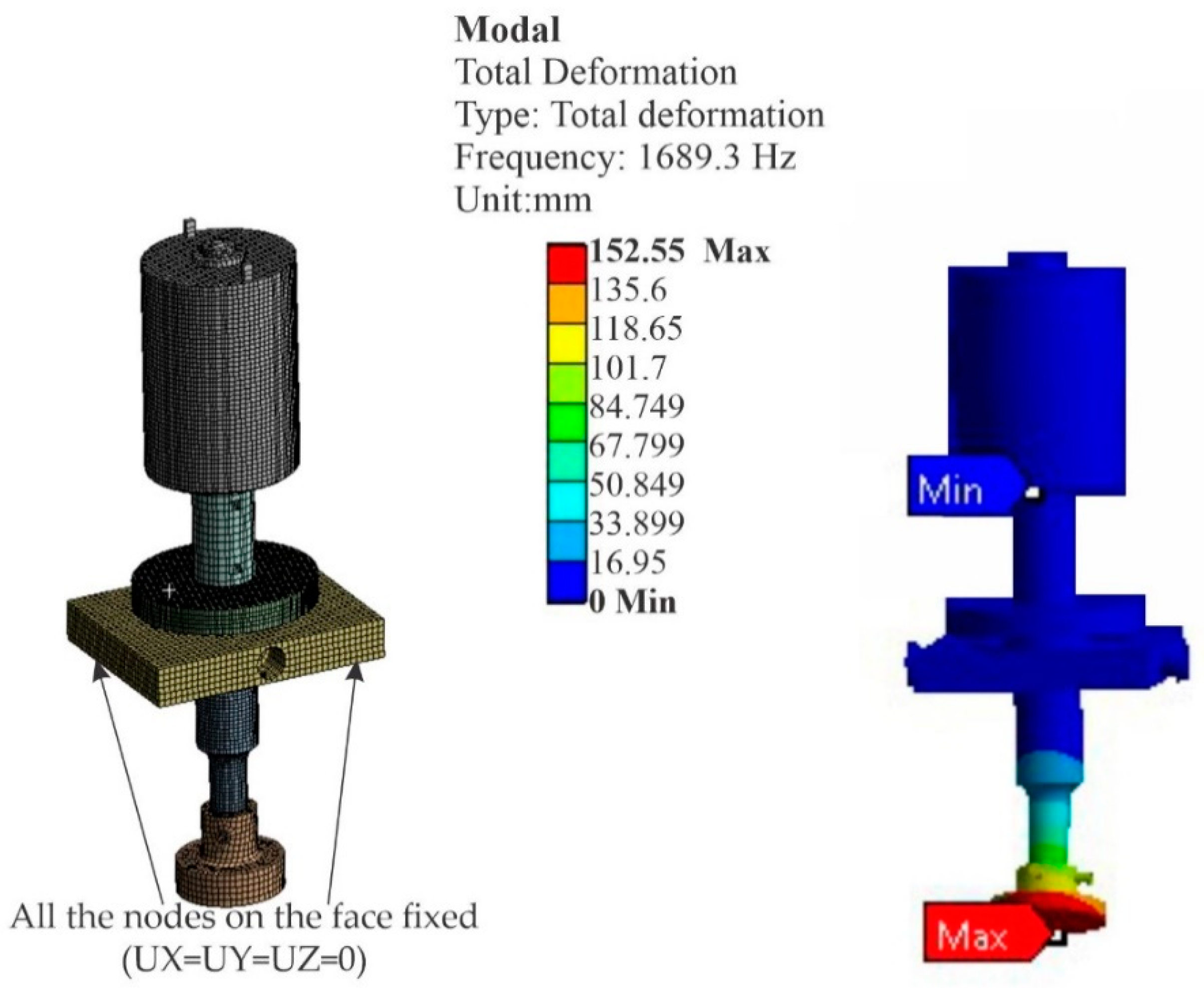
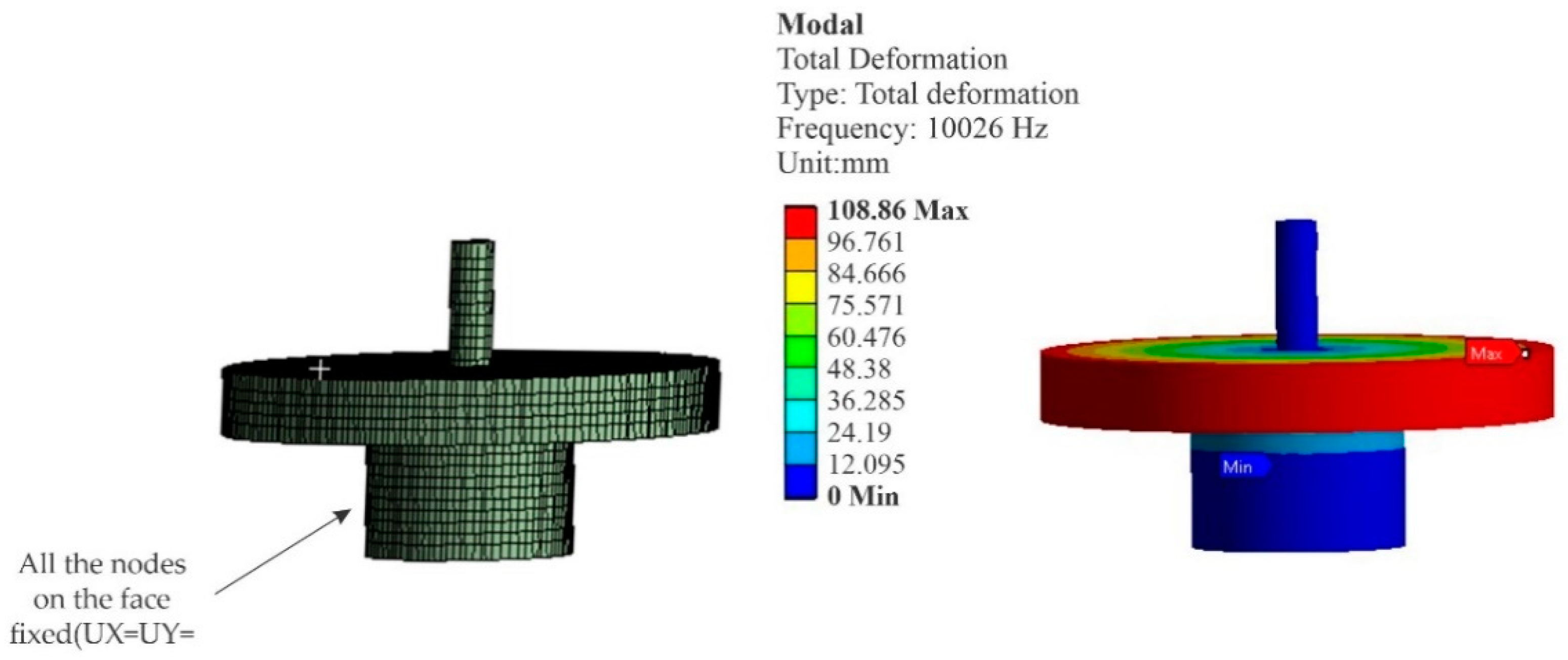
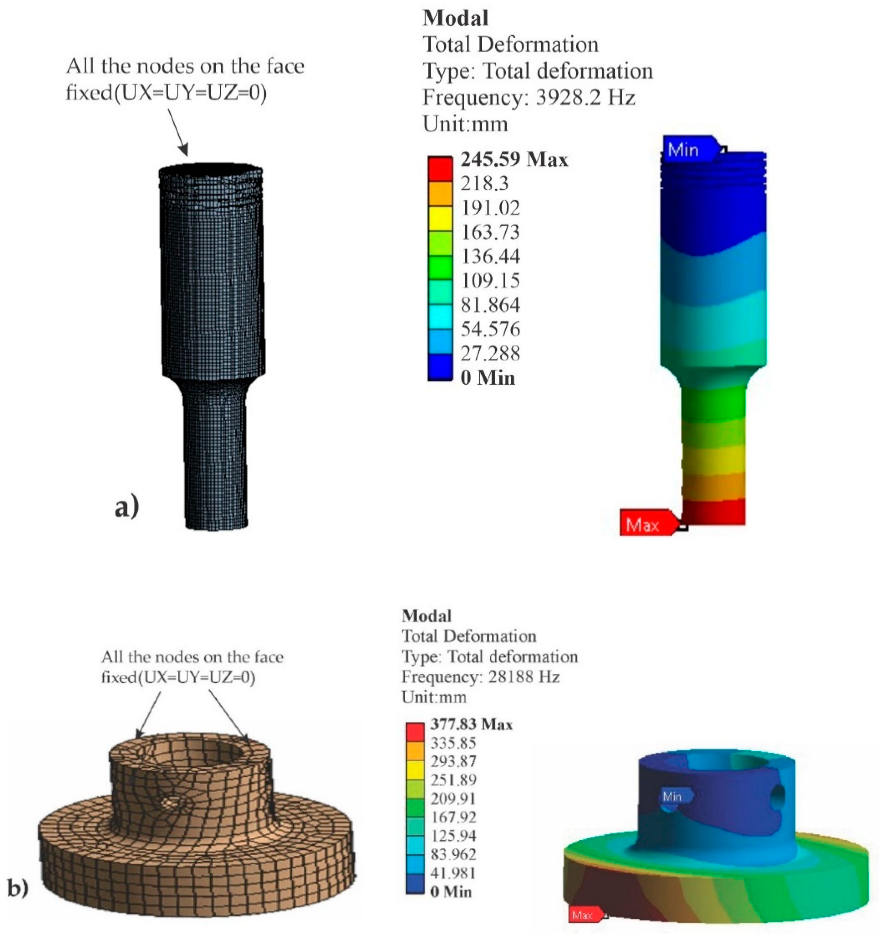
3.4. Finite Element Analysis (FEA)
- (1)
- A minimal part or element analysis was performed on the rheometer design. This led to the elimination of some nonessential accessories, helping to meet the requirement of easy maintenance.
- (2)
- Small marks were made on the plates and laminates to increase the stiffness and prevent susceptibility to excessive vibrations and loosening.
- (3)
- The rotation shaft section was modified at the base, where the test probe is placed, to avoid excessive movements due to vibration based on the results obtained in the FMEA and FEA.
- (4)
- The section of the upper rear part of the structure was modified to avoid movements due to vibration and possible failures caused by mechanical fatigue.
- (5)
- The space devoted to the battery holder for the sensor power source was improved.
- (6)
- Improvements to the electrical components were taken into account in the instrumentation section.
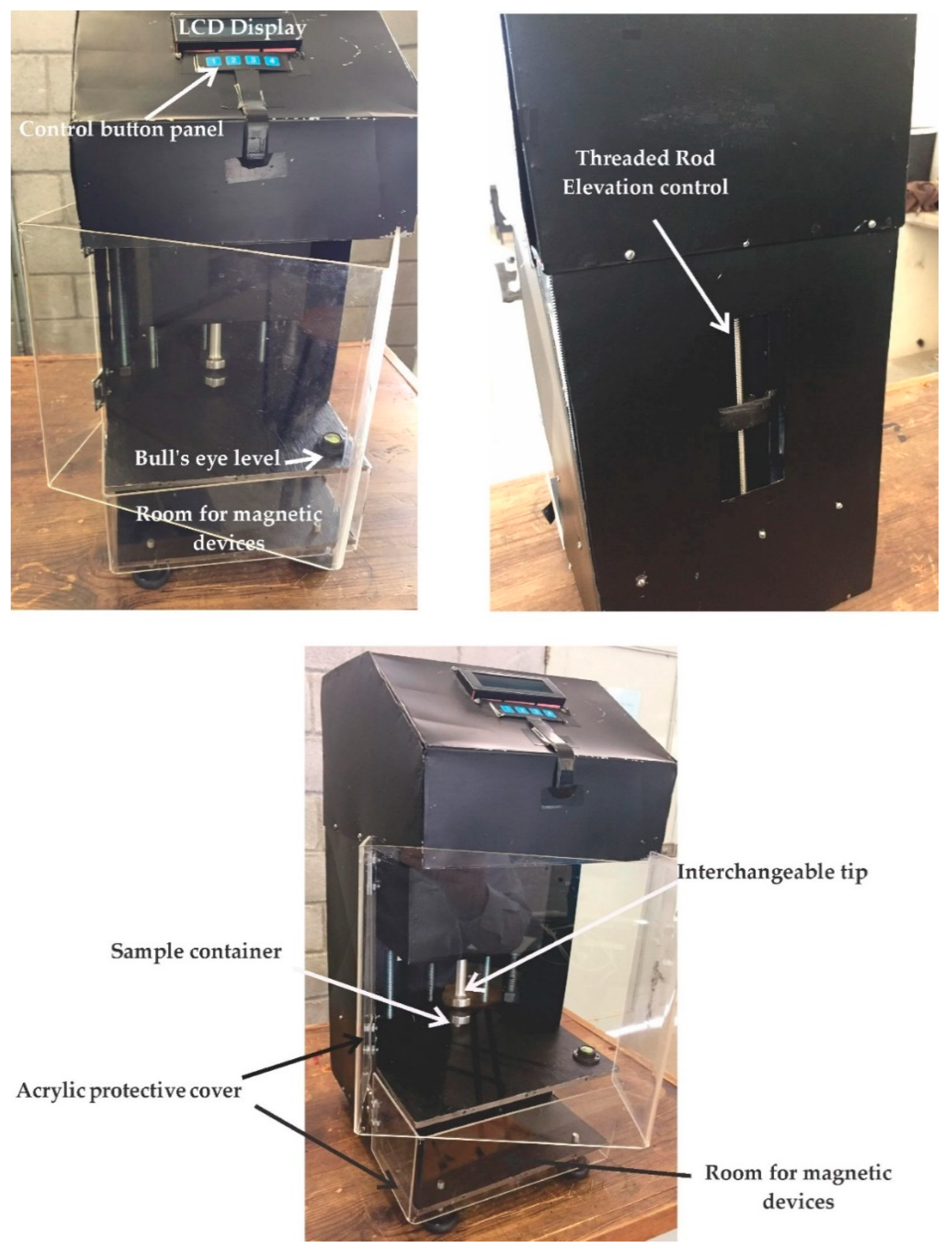
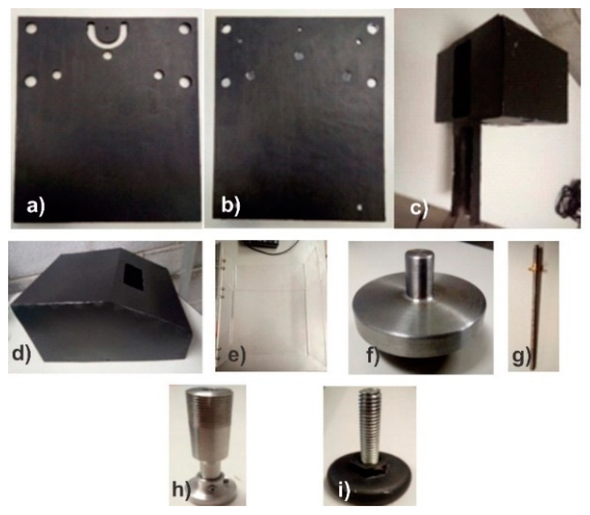
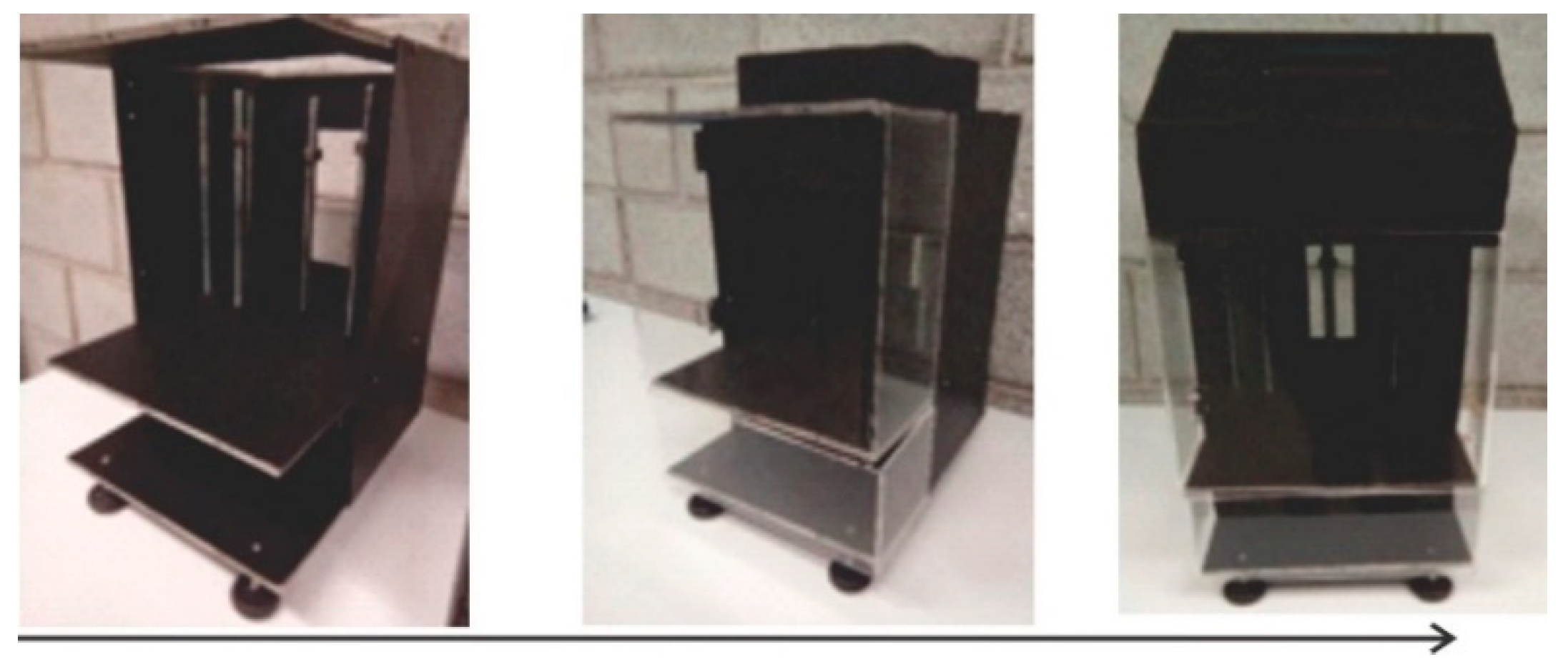
3.5. Rheometer Manufacturing Process
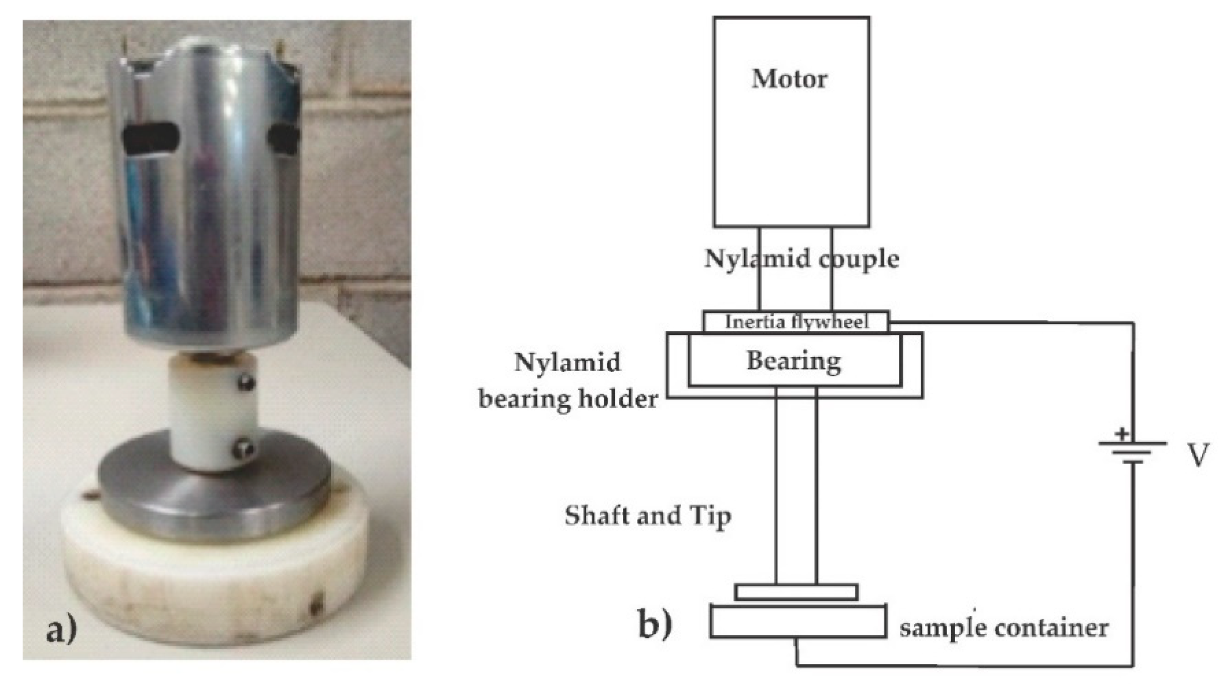
3.6. Instrumentation and Implementation
- (a)
- Open platform Arduino UNO boards, which facilitate microcontroller programming.
- (b)
- A DHT11 digital temperature and humidity sensor, which uses a capacitive humidity sensor and a thermistor to measure the surrounding air and only one pin to read the data.
- (c)
- An FC-03 Infrared Sensor Encoder, a device responsible for converting angular movement into electrical pulses which can be interpreted by the system controller.
- (d)
- An Arduino button panel, control element.
- (e)
- An H Bridge L298N, a circuit that allows controlling the direction of the rotation and speed in DC motors.
- (f)
- An LCD display and an I2C Adapter for LCD displays with microcontrollers.
4. Discussion
Limitations and Expected Impact
- The sample of participants considered for the requirements analysis and for the design process should be improved, involving more experts in the field of rheology, equipment vendors, users, and analysts.
- A weakness found during the stage is the lack of an in-depth analysis of the technical details in the design of the proposed solution.
- It would be very convenient to update the failure mode analysis (FMEA) with field evaluations of the experimental performance in order to continue improving and adjusting the rheometer design.
- The verification stage of the experimental operation of the rheometer would give certainty for industrial production and would give feedback on the entire design process.
- An ergonomic analysis of man-machine interaction would undoubtedly strengthen the development process of the rheometer as a product.
5. Conclusions
Author Contributions
Funding
Acknowledgments
Conflicts of Interest
References
- Schramm, G. A Practical Approach to Rheology and Rheometry; Block, H., Kelly, J.P., Eds.; Gebrueder Haake: Karlsruhe, Germany, 1994. [Google Scholar]
- Barnes, H.A.; Hutton, J.F.; Walters, K. An Introduction to Rheology; Rheology Series; Elsevier Science Publishers: Amsterdam, The Netherlands, 1989. [Google Scholar]
- Halsey, T.C.; Toor, W. Structure of electrorheological fluids. Phys. Rev. Lett. 1990, 65, 2820–2823. [Google Scholar] [CrossRef] [PubMed]
- García-Ortiz, J.H.; Sadek, S.H.; Galindo-Rosales, F.J. Influence of the Polarity of the Electric Field on Electrorheometry. Appl. Sci. 2019, 9, 5273. [Google Scholar] [CrossRef] [Green Version]
- Lang, L.; Alexandrov, S.; Lyamina, E.; Dinh, V.M. The Behavior of Melts with Vanishing Viscosity in the Cone-and-Plate Rheometer. Appl. Sci. 2020, 10, 172. [Google Scholar] [CrossRef] [Green Version]
- Wang, H.; Jiao, J.; Wang, Y.; Du, W. Feasibility of Using Gangue and Fly Ash as Filling Slurry Materials. Processes 2018, 6, 232. [Google Scholar] [CrossRef] [Green Version]
- Wang, H.; Hassan, E.A.M.; Memon, H.; Elagib, T.H.H.; Abad AllaIdris, F. Characterization of Natural Composites Fabricated from Abutilon-Fiber-Reinforced Poly (Lactic Acid). Processes 2019, 7, 583. [Google Scholar] [CrossRef] [Green Version]
- De la Cruz Martínez, A.; Delgado Portales, R.E.; Pérez Martínez, J.D.; González Ramírez, J.E.; Villalobos Lara, A.D.; Borras Enríquez, A.J.; Moscosa Santillán, M. Estimation of Ice Cream Mixture Viscosity during Batch Crystallization in a Scraped Surface Heat Exchanger. Processes 2020, 8, 167. [Google Scholar] [CrossRef] [Green Version]
- Li, D.; Li, G.; Chen, Y.; Man, J.; Wu, Q.; Zhang, M.; Chen, H.; Zhang, Y. The Impact of Erythrocytes Injury on Blood Flow in Bionic Arteriole with Stenosis Segment. Processes 2019, 7, 372. [Google Scholar] [CrossRef] [Green Version]
- Wang, Y.; Huang, Y.; Hao, Y. Experimental Study and Application of Rheological Properties of Coal Gangue-Fly Ash Backfill Slurry. Processes 2020, 8, 284. [Google Scholar] [CrossRef] [Green Version]
- García-Ortiz, J.H.; Galindo-Rosales, F.J. Extensional Magnetorheology as a Tool for Optimizing the Formulation of Ferrofluids in Oil-Spill Clean-Up Processes. Processes 2020, 8, 597. [Google Scholar] [CrossRef]
- Huang, W.; Wang, D.; He, P.; Long, X.; Tong, B.; Tian, J.; Yu, P. Rheological Characteristics Evaluation of Bitumen Composites Containing Rock Asphalt and Diatomite. Appl. Sci. 2019, 9, 1023. [Google Scholar] [CrossRef] [Green Version]
- Cruz, P.; Martínez, F.J.; Pineda, Z.; Morales, J.; Hernández, J.F.; Reyes, M.; Figueroa, R.A. Perspectiva del uso de amortiguadores inteligentes en vehículos eléctricos. In Tendencias Actuales de Fuentes de Energía Renovables; UASLP: Matehuala, México, 2017; pp. 26–31. ISBN 978-607-535-017-2. [Google Scholar]
- Pineda, R.Z.; Martínez, L.F.J.; Cruz, A.P. Amortiguadores inteligentes y reología. Univ. Potos. 2017, 216, 28–33. [Google Scholar]
- Zapateiro, M.; Pozo, F.; Karimi, H.R.; Luo, N. Semiactive Control Methodologies for Suspension Control with Magnetorheological Dampers. IEEE/ASME Trans. Mechatron. 2012, 17, 370–380. [Google Scholar] [CrossRef] [Green Version]
- da Silva, V.B.; da Costa, M.P. Influence of Processing on Rheological and Textural Characteristics of Goat and Sheep Milk Beverages and Methods of Analysis. In Processing and Sustainability of Beverages; Grumezescu, A.M., Holban, A.M., Eds.; Woodhead Publishing: Sawston, Cambridge, 2019; pp. 373–412. ISBN 9780128152591. [Google Scholar] [CrossRef]
- Akao, Y. Development history of quality function deployment. In The Customer Driven Approach to Quality Planning and Deployment; Asian Productivity Organization: Minato, Tokyo, Japan, 1994. [Google Scholar]
- Kuijt-Evers, L.F.M.; Morel, K.P.N.; Eikelenberg, N.L.W.; Vink, P. Application of the QFD as a design approach to ensure comfort in using hand tools: Can the design team complete the House of Quality appropriately? Appl. Ergon. 2009, 40, 519–526. [Google Scholar] [CrossRef] [PubMed]
- Utne, I.B. Improving the environmental performance of the fishing fleet by use of Quality Function Deployment (QFD). J. Clean. Prod. 2009, 17, 724–731. [Google Scholar] [CrossRef]
- Elena, F.; Gazizulina, A.; Eskina, E.; Ostapenko, M.; Aidarov, D. Development of QFD Methodology. In Quality, IT and Business Operations; Springer Proceedings in Business and Economics; Kapur, P., Kumar, U., Verma, A., Eds.; Springer: Singapore, 2018. [Google Scholar]
- Tan, X.; Xiong, W. Improving Product Quality Based on QFD and FMEA Theory. In 2020 Prognostics and Health Management Conference (PHM-Besançon); IEEE: Besancon, France, 2020; pp. 274–282. [Google Scholar] [CrossRef]
- Mukherjee, S.P. Improving Process Quality. In Quality. India Studies in Business and Economics; Springer: Singapore, 2019; ISBN 978-981-13-1270-0. [Google Scholar] [CrossRef]
- Franceschini, F.; Maisano, D. A new proposal to improve the customer competitive benchmarking in QFD. J. Qual. Eng. 2018, 30, 730–761. [Google Scholar] [CrossRef]
- Freddi, A.; Salmon, M. Design Principles and Methodologies from Conceptualization to First Prototyping with Examples and Case Studies; Springer International Publishing: Cham, Switzerland, 2019; ISBN 978-3-319-95341-0. [Google Scholar]
- Almannai, B.; Greenough, R.; Kay, J. A decision support tool based on QFD and FMEA for the selection of manufacturing automation technologies. Robot. Comput.-Integr. Manuf. 2008, 24, 501–507. [Google Scholar] [CrossRef]
- Zadry, H.R.; Rahmayanti, D.; Susanti, L.; Fatrias, D. Identification of Design Requirements for Ergonomic Long Spinal Board Using Quality Function Deployment (QFD). Procedia Manuf. 2015, 3, 4673–4680. [Google Scholar] [CrossRef] [Green Version]
- Marsot, J. QFD: A methodological tool for integration of ergonomics at the design stage. Appl. Ergon. 2005, 36, 185–192. [Google Scholar] [CrossRef]
- Mayda, M.; Choi, S. A reliability-based design framework for early stages of design process. J. Braz. Soc. Mech. Sci. Eng. 2017, 39, 2105–2120. [Google Scholar] [CrossRef]
- Wolniak, E.R.; Sȩdek, A. Using QFD method for the ecological designing of products and services. Qual. Quant. 2009, 43, 695–701. [Google Scholar] [CrossRef]
- Trafialek, J.; Kolanowski, W. Application of Failure Mode and Effect Analysis (FMEA) for audit of HACCP system. Food Control 2014, 44, 35–44. [Google Scholar] [CrossRef]
- Liu, H.; Deng, X.; Jiang, W. Risk Evaluation in Failure Mode and Effects Analysis Using Fuzzy Measure and Fuzzy Integral. Symmetry 2017, 9, 162. [Google Scholar] [CrossRef] [Green Version]
- Zheng, Y.; Johnson, R.; Larson, G. Minimizing treatment planning errors in proton therapy using failure mode and effects analysis. Int. J. Radiat. Oncol. Biol. Phys. 2016, 43, 2904–2910. [Google Scholar] [CrossRef] [PubMed]
- Manger, R.P.; Paxton, A.B.; Pawlicki, T.; Kim, G.Y. Failure mode and effects analysis and fault tree analysis of surface image guided cranial radiosurgery. Med. Phys. 2015, 42, 2449–2461. [Google Scholar] [CrossRef] [PubMed]
- Kim, K.M.; Yun, N.; Yun, H.J.; Dong, H.L.; Cho, H.H. Failure analysis in after shell section of gas turbine combustion liner under base-load operation. Eng. Fail. Anal. 2010, 17, 848–856. [Google Scholar] [CrossRef]
- Fiorineschi, L.; Becattini, N.; Borgianni, Y.; Rotini, F. Testing a New Structured Tool for Supporting Requirements’ Formulation and Decomposition. Appl. Sci. 2020, 10, 3259. [Google Scholar] [CrossRef]
- Kroll, E. Design theory and conceptual design: Contrasting functional decomposition and morphology with parameter analysis. Res. Eng. Des. 2013, 24, 165–183. [Google Scholar] [CrossRef]
- Pahl, G.; Beitz, W.; Feldhusen, J.; Grote, K.H. Engineering Design, 3rd ed.; Springer: London, UK, 2007. [Google Scholar] [CrossRef]
- Jinks, T. The 5W1H Method. In Psychological Perspectives on Reality, Consciousness and Paranormal Experience; Palgrave Macmillan: Cham, Switzerland, 2019. [Google Scholar] [CrossRef]
- Altshuller, G. Creativity as an Exact Science: The Theory of the Solution of Inventive Problems; Gordon and Breach Science Publishing: New York, NY, USA, 1984; ISBN 0-677-21230-5. [Google Scholar]
- Yamashina, H.; Ito, T.; Kawada, H. Innovative product development process by integrating QFD and TRIZ. Int. J. Prod. Res. 2002, 40, 1031–1050. [Google Scholar] [CrossRef]
- Whiteley, M.; Dunnett, S.; Jackson, L. Failure Mode and Effect Analysis, and Fault Tree Analysis of Polymer Electrolyte Membrane Fuel Cells. Int. J. Hydrog. Energy 2016, 41, 1187–1202. [Google Scholar] [CrossRef] [Green Version]
- Hughes, T.J.R. The Finite Element Method: Linear Static and Dynamic Finite Element Analysis, 1st ed.; Dover Publications: Mineola, NY, USA, 2000; ISBN 978-0486411811. [Google Scholar]
- Strang, G.; Fix, G.J. An Analysis of the Finite Element Method, 2nd ed.; Series in Automatic Computation; Prentice-Hall, Inc.: Englewood Clifs, NJ, USA, 1973. [Google Scholar]
- Zhang, H.C. Manufacturing Process Planning. In Handbook of Automation and Manufacturing System; Dorf, R.C., Kusiak, A., Eds.; John Wiley & Sons: New York, NY, USA, 1994; pp. 587–616. ISBN 978-0-471-55218-5. [Google Scholar]
- Swamidass, P.M. Encyclopedia of Production and Manufacturing Management; Springer: New York, NY, USA, 2000; p. 980. ISBN 978-0-7923-8630-8. [Google Scholar] [CrossRef]
- Ouriev, B.N.; Uriev, N.B. Influence of vibration on structure rheological properties of a highly concentrated suspension. Meas. Sci. Technol. 2005, 16, 1691–1700. [Google Scholar]
- ANSYS Mechanical APDL Element Reference; ANSYS, Inc.: Canonsburg, PA, USA, 2011.
- ANSYS Meshing User’s Guide; ANSYS, Inc.: Canonsburg, PA, USA, 2013.
- Fiorineschi, L.; Papini, S.; Pugi, L.; Rindi, A.; Rotini, F. Systematic design of a new gearbox for concrete mixers. J. Eng. Des. Technol. 2020. [Google Scholar] [CrossRef]


| D Value | Detection | O value | Occurrence | S Value | Severity |
|---|---|---|---|---|---|
| 1 | Almost certain | 1 | Extremely Unlikely | 1 | None |
| 2 | Very High | 2 | Unlikely | 2 | Very Slight |
| 3 | High | 3 | Minimal | 3 | Minimal |
| 4 | Moderately high | 4 | Very Slight Probability | 4 | Minor |
| 5 | Moderate | 5 | Slight Probability | 5 | Moderate |
| 6 | Low | 6 | Low Probability | 6 | Significant |
| 7 | Very low | 7 | Medium Probability | 7 | Serious |
| 8 | Remote | 8 | Moderately High Probability | 8 | Very Serious |
| 9 | Very remote | 9 | High Probability | 9 | Extremely Serious |
| 10 | Absolute uncertainty | 10 | Extremely High Probability | 10 | Hazardous |
| RPN | Severity | Description |
|---|---|---|
| RPN < 50 | Minor | This mode of failure can be detected by the company; it means a simple change in the design, unless the mode of failure is included in the standard. |
| 50 < RPN < 100 | Significant | The Priority Risk Number of this failure mode can be decreased after an adjustment to the design in the company’s laboratories. |
| RPN > 100 | Very Serious or Hazardous | This mode of failure must be reduced or eliminated through the various laboratory tests that are performed, or if necessary we must change the design concept. If it is not diminished, the product cannot be sold to the market. |
| Process Capacity Sheet | Approved by: | Part No. | Application | Entered by: | Date: | |||
| Part Name: | Number of Parts | Line: | ||||||
| Step Name | Machine | Basic Time | Tool Change | Processing Capacity/Shift | Remarks | |||
| Manual | Auto | Completion | Change | Time | ||||
| Customer Requirements | Importance or Weights | Customer Requirements | Importance or Weights |
|---|---|---|---|
| Easy to use | 5 | Minimum error margin | 5 |
| Display results on an LCD display | 5 | Use with any fluid—electro and magnet | 3 |
| Economic | 3 | Store data | 3 |
| Aesthetic | 3 | Automatic calculations | 5 |
| Small size | 3 | Easy to manufacture | 5 |
| Strong and lightweight | 1 | Secure | 5 |
| Portable | 5 | Easy maintenance | 5 |
| Detachable-interchangeable tips | 3 | ||
| Item | Potential Failure Mode | Potential Effects | S | Potential Causes of Failure | O | Current Controls for Prevention | D | RPN | Recommended Actions |
|---|---|---|---|---|---|---|---|---|---|
| Motor | Damage to the motor armature | Component failures | 10 | Motor overload | 8 | Inspection and preventive maintenance | 6 | 480 | Proper maintenance and allow for cooling |
| Bearing damage | Deterioration of the elements | Excessive load, poor lubrication | Allow cooling and lubrication | ||||||
| Short circuit | Probability of damage to the other components | Contact with water, contact between wires | Protect from moisture, check connections | ||||||
| Motor misalignment | Destruction of the components | Sudden movements | Avoid sudden movements | ||||||
| Rotor (shaft and tip) | Plate misalignment | Wrong results | 5 | Plate friction, overloading the motor | 2 | Preventive maintenance and adjustment of components | 8 | 80 | Check multi-directional leveling (bull’s eye level) |
| Gear wear | Do not rotate the shaft | Wear due to lack of lubricant | Preventive maintenance and lubrication | ||||||
| Plates | Misleveled plates | Measurement error | 5 | Not having a bubble leveler | 2 | Preventive maintenance, lubricating, and checking levels | 5 | 50 | Check multi-directional leveling |
| Loosening | Test point parallelism problems | Poor installation of components | Checking component adjustment | ||||||
| Basis and structure | Fracture of the plates | Measurement error | 5 | Fracture due to misuse | 2 | Replace component | 5 | 50 | Replace the part |
| Item | Potential Failure Mode | Potential Effects | S | Potential Causes of Failure | O | Current Controls for Prevention | D | RPN | Recommended Actions |
|---|---|---|---|---|---|---|---|---|---|
| Potentiometer | Bad installation | Lack of speed control | 7 | Installation mistakes | 2 | Install components correctly, allow proper cooling | 7 | 98 | Verify correct installation |
| Heating | Damaged or burnt components | Risk of short circuit | Turn off rheometer and allow cooling | ||||||
| LCD display | Burn | Error in the speed indicated on the LCD display | 6 | Short circuit | 4 | Protect it from falls and water contact | 1 | 24 | Only connect at the time of testing |
| Break | Does not turn on the LCD display | Falls, blows, misuse | Avoid hitting the LCD display | ||||||
| Short circuit | Does not turn on the LCD display | Electric shock, overheating | Protect against humidity | ||||||
| Battery holder | Electrical discharge | No electric power | 8 | No electric power | 5 | Use properly, protect from the humidity and clean | 5 | 200 | Check electrical connection |
| Incorrect Electrical Wiring | Poorly connected wires | Check wiring and connection | |||||||
| Short circuit | The other components are put at risk | overheating, contact with water | Protecting it from humidity and proper use | ||||||
| USB port | Installation mistakes | Disconnected USB Data is not saved | 4 | Bad connection of the USB ports | 2 | Replacing components | 6 | 48 | Verify correct installation |
| Problem with the interface | Data is not saved | Remove and reinsert it | |||||||
| Control Panel | Installation mistakes | lack of control over functions | 7 | Not installing the component correctly | 2 | Control panel for rheometer control | 5 | 70 | Verify correct installation |
| Component failure | Difficulty in pressing buttons | Poor installation, disconnected wires | Verify correct installation |
| Control Manufacturing Processes (CMP) | Sheet Process “Sheet Metal Casing” | Part: 9 | ||
|---|---|---|---|---|
| Sheet: 9 | ||||
| Title Sheet Metal Casing | Material Galvanized Sheet | Dimensions 300 × 250 mm 160 × 80 mm | Estimated Time 1 h 30 min. | |
 |  |  |  | |
| Op. | Description | Tools and Equipment | Working Conditions | Estimated Operation Time |
| 1 | Trace the dimensions on the cardboard sheets | Tape measure and square | Manual | 20 min. |
| 2 | Using the cardboard, mark the exact measurements on the galvanized Sheet | Square and marker | Manual | 10 min. |
| 3 | Cut the galvanized sheet according to the proposed measurements | Sheet metal scissors | Manual | 10 min. |
| 4 | Drill holes in the galvanized sheet | Drill and bit set | Manual | 15 min. |
| 5 | Bend the galvanized sheet to the proposed dimensions | Hydraulic bending press | Manual | 10 min. |
| 6 | Weld the indicated flaps of the galvanized sheet | Automatic spot welder | Manual | 15 min. |
| 7 | Sand the galvanized sheet | Sponge sanding pads and ultra fine sand paper | Manual | 10 min. |
| 8 | Painting galvanized sheet | Air paint gun | Manual | 20 min. |
| Comments: The dimensions indicated on the cardboard sheet are drawn first, so that there are no errors in the lines. Once the dimensions have been completed exactly, they are transferred to the sheet to avoid waste or possible errors. | ||||
© 2020 by the authors. Licensee MDPI, Basel, Switzerland. This article is an open access article distributed under the terms and conditions of the Creative Commons Attribution (CC BY) license (http://creativecommons.org/licenses/by/4.0/).
Share and Cite
Hernández-Rangel, F.J.; Saavedra-Leos, M.Z.; Morales-Morales, J.; Bautista-Santos, H.; Reyes-Herrera, V.A.; Rodríguez-Lelis, J.M.; Cruz-Alcantar, P. Continuous Improvement Process in the Development of a Low-Cost Rotational Rheometer. Processes 2020, 8, 935. https://doi.org/10.3390/pr8080935
Hernández-Rangel FJ, Saavedra-Leos MZ, Morales-Morales J, Bautista-Santos H, Reyes-Herrera VA, Rodríguez-Lelis JM, Cruz-Alcantar P. Continuous Improvement Process in the Development of a Low-Cost Rotational Rheometer. Processes. 2020; 8(8):935. https://doi.org/10.3390/pr8080935
Chicago/Turabian StyleHernández-Rangel, Francisco J., María Z. Saavedra-Leos, Josefa Morales-Morales, Horacio Bautista-Santos, Vladimir A. Reyes-Herrera, José M. Rodríguez-Lelis, and Pedro Cruz-Alcantar. 2020. "Continuous Improvement Process in the Development of a Low-Cost Rotational Rheometer" Processes 8, no. 8: 935. https://doi.org/10.3390/pr8080935
APA StyleHernández-Rangel, F. J., Saavedra-Leos, M. Z., Morales-Morales, J., Bautista-Santos, H., Reyes-Herrera, V. A., Rodríguez-Lelis, J. M., & Cruz-Alcantar, P. (2020). Continuous Improvement Process in the Development of a Low-Cost Rotational Rheometer. Processes, 8(8), 935. https://doi.org/10.3390/pr8080935