Article

Optimal Scheduling of Island Microgrid with Seawater-Pumped Storage Station and Renewable Energy

Faculty of Electric Power Engineering, Kunming University of Science and Technology, Kunming 650500, China
*
Author to whom correspondence should be addressed.
These authors have equal contribution to this study and are co-first authors of this paper.
Processes 2020, 8(6), 737; https://doi.org/10.3390/pr8060737
Submission received: 7 May 2020 / Revised: 17 June 2020 / Accepted: 22 June 2020 / Published: 24 June 2020
(This article belongs to the Special Issue Energy Storage System: Integration, Power Quality, and Operation)

Abstract

:
The rapid development of renewable energy, represented by wind and photovoltaic, provides a new solution for island power supplies. However, due to the intermittent and random nature of renewable energy, a microgrid needs energy-storage components to stabilize its power supply when coupled with them. The emergence of seawater-pumped storage stations provides a new method to offset the shortage of island power supply. In this study, an optimal scheduling of island microgrid is proposed, which uses seawater-pumped storage station as the energy storage equipment to cooperate with wind, photovoltaic and diesel generator. First, a mathematic formulation of seawater-pumped storage station with renewable energy is presented. Then, to reach the goal of economic dispatch, an optimal scheduling model of island microgrid is established with the consideration of both respective operation constraints and island load requirements. Finally, the effectiveness of the proposed model is verified by an island microgrid over two typical seasons. The simulation results show that the proposed framework not only increases the usage of renewable energy, but also improves the operational reliability and economy of island microgrids.

1. Introduction

As many island micro grids are not connected with the continent [1,2,3], distributed renewable power and generators have become the major sources of island power supply. Hence, the reliability of island microgrid would be affected by random variability of renewable energy and loads [4,5]. To achieve the goal of reliable operation, there is an urgent need to adopt power storage equipment for regulation [6,7].
Pumped storage is the most widely used power storage technology that combines the advantages of high efficiency, large capacity, long storage period and maturity all together [8,9,10]. Since the ocean may be regarded as an infinite natural reservoir, building seawater-pumped storage stations on islands has some natural advantages. These pumped-storage stations play an auxiliary role in island power supply and can be considered as a new type of energy storage system [11,12]. Therefore, it is both promising and necessary to conduct research on the optimal scheduling of island microgrid with seawater-pumped storage stations.
In terms of the research on seawater-pumped storage station, Japanese are at the forefront. They built the first experimental station on Okinawa Island with a total installed capacity of 30 MW in 1999 [13]. In addition, some Japanese scholars have carried out theoretical research in the field of power system with seawater-pumped storage stations and renewable energy. For example, a construction and operation scheme of seawater-pumped storage station is proposed in reference [14]. In this study, seawater-pumped storage station was regarded as a means to utilize wind power effectively. Based on the model of renewable energy and seawater-pumped storage station, reference [15] suggested a scheduling method for island microgrid with wind–light-marine storage. Reference [16] studied the dispatching model of seawater-pumped storage station with renewable energy and stated a multiple time scales optimal scheduling method for active distribution network. The coordinate dispatching method of seawater-pumped storage station and wind farms provides a new idea of improving power supply capacity is shown in reference [17]. In reference [18], based on the working mechanism of seawater-pumped storage station, the role it played in improving island power supply capacity is studied, and the coordinate operation prospect of seawater-pumped storage station and renewable energy is introduced. References [19,20] summarized the sites where seawater-pumped storage station can be built in China. In addition, the difficulties during construction process were also investigated. By taking one island microgrid in Spain as example, reference [21] studied the coordinated optimal dispatching method with the participation of seawater-pumped storage station. Aiming to solve the reliable operation problem caused by photovoltaic, reference [22] suggested a coordinated optimal operation method for photovoltaic generation system with seawater-pumped storage stations, and the superiority and validity of proposed model were also verified by a simulation of optimal operation in Italy. In reference [23], the coordinated optimal operation method of seawater-pumped storage station and offshore wind power generations is studied, while a series of simulations on Rhode Island were performed to ensure the effectiveness of proposed method. Coordinated operation schemes of wind-power-generation systems with compressed-air energy storage, seawater-pumped storage station and heat energy storage system are discussed in reference [24], and the advantages of each scheme were also tested by simulations of a practical power grid. In reference [25], seawater-pumped storage stations were used to improve the output of wind power, and an experimental marine storage power station was chosen to examine the effectiveness.
Many scholars have conducted impressive research on the operation characteristics of island microgrids with seawater-pumped storage station and renewable energy. However, the research of seawater-pumped storage station remains in the theoretical stage, as many challenges in the optimal scheduling of island microgrids with seawater-pumped storage stations and renewable energy are still ahead of us. Due to the scarcity of optimal scheduling methods for island microgrid systems, some key technical problems are still waiting to be solved.
This study focuses on the days-ahead optimal scheduling method—as well as the model of island microgrids that couple with seawater-pumped storage stations and renewable energy. The main contributions of this article are as follows:
  • Based on the equivalent model of seawater-pumped storage station’s reservoir, the optimal scheduling method model of seawater-pumped storage station in island microgrid is established for the first time;
  • A coordinated optimal dispatching model of seawater-pumped storage station and renewable energy is suggested;
  • An optimal scheduling method for island microgrid with seawater-pumped storage station is proposed for the first time.

2. Problem Description and Optimization Framework

2.1. Microgrid Description

Electric power supply capacity of island micro grids is relatively weak, as a result of being separated from the continent. Most of them rely heavily on the distributed generators and renewable energy generation systems for power supply. In view of the randomness of renewable energy output, the participation of energy storage equipment is urgently needed.
The ocean is a natural reservoir for islands. By building seawater-pumped storage stations, not only can power-supply pressure be alleviated, but also the power-supply capability can be improved accordingly. A proposed island microgrid system with a seawater-pumped storage station and renewable energy resources is shown in Figure 1, which is powered by both diesel generators and renewable energy. To maintain energy balance, the seawater-pumped storage station, renewable energy, diesel generator and interruptible loads are all involved in the power regulation of the island microgrid.

2.2. Optimization Framework

In this study, the optimal scheduling of proposed island microgrid was studied. Optimal scheduling requires input data such as the predictions of renewable energy and load output, parameters of both seawater-pumped storage station and distributed generators. The input and output data that required by proposed optimization frameworks are summarized in Figure 2.
Input data:
  • Short-term forecast data of renewable energy and loads;
  • Parameters of seawater-pumped storage station;
  • Parameters of interruptible loads, diesel generator, wind turbines and photovoltaic system;
Variables:
  • Power outputs of diesel generator and seawater-pumped storage unit;
  • State variables of interruptible loads, diesel generator, seawater-pumped storage unit in generating and pumping status;
  • Wind and photovoltaic power curtailments;
  • Curtailment of rigid loads.

3. Scheduling Model of the Island Microgrid

The island microgrid system proposed in this study contains seawater-pumped storage stations, renewable energy and diesel generators. In this section, the scheduling models of these components are built, respectively, and an optimal scheduling model of island microgrid is established accordingly. The specific process is detailed below.

3.1. Model of Variable-Speed Seawater-Pumped Storage Station

The structure of a traditional pumped-storage station includes one generator unit, one pumping station and upper and lower reservoirs. By using variable speed drive equipment, the power-regulation ability of the pumped storage station is improved, and the curtailments of renewable energy and rigid load—as well as the use of diesel generators can be further reduced. Since the lower reservoir of seawater-pumped storage station is the ocean, the water resource is unlimited. Hence, the capacity of seawater-pumped storage station can be considered as almost infinite, and only the water amount of the upper reservoir needs to be considered in the optimal scheduling. The operational model of a variable speed seawater-pumped storage station can be expressed as follows.

3.1.1. Equivalent Reservoir Model of Variable-Speed Seawater-Pumped Storage Station

As the lower reservoir of seawater-pumped storage stations can be treated as infinite, the water amount of upper reservoir is similar to the state-of-charge (SOC) of chemical-energy storage batteries. The water level of the upper reservoir in seawater-pumped storage station is denoted by SOCsea in Equation (1) as follows:
S O C s e a ( t ) = Q u p ( t ) Q max
where Qup(t) is the seawater quantity stored in the upper reservoir in period t, which is limited by the maximum storage capacity of the upper reservoir (Qmax).
In period t, the quantity of seawater stored in the upper reservoir is given as Equation (2).
Q u p ( t ) = ( 1 l ) × Q u p ( t 1 ) + t 1 t q p u m p ( t ) d t t 1 t q g e n ( t ) d t
where L is the leakage loss coefficient of evaporation, which is equivalent to the self-discharge rate of chemical energy storage batteries. qpump(t) represents the water flow rate that pumped from the sea in period t, and the water flow rate that pumped into the turbine in period t can be expressed as qgen(t).

3.1.2. Generating and Pumping Models

The output power of the pumped station under generating mode can be calculated by Equation (3):
P g e n ( t ) = k g e n ρ g h × t 1 t q g e n ( t ) d t
where kgen is the efficiency of the turbine generator. ρ denotes the density of seawater (1050 kg/m3). The gravity acceleration (9.8 m/s2) is expressed as g and the drop between generator and the lower reservoir is represented by h. Given that the drop between the upper and lower reservoirs is much greater than the water level of the upper reservoir, the impact imposed by the SOC on h is neglected.
When working in pumping mode, the energy requirements of a pumped-storage station are fulfilled by local active distribution network directly. The water volume sucked from the sea can be expressed as Equation (4):
t 1 t q p u m p ( t ) d t = k p u m p P p u m p ( t ) ρ g h
where kpump denotes the efficiency of the pump–motor unit, while Ppump(t) represents the input power of pumping mode in period t.

3.1.3. Operation and Maintenance Costs of Variable-Speed Seawater-Pumped Storage Station

Seawater has a high salt content that is corrosive to pipelines and can increase system maintenance costs. Hence, the total operation costs of seawater-pumped storage station contain not only the costs of generating and pumping unit, but also the costs of pipelines and other components. Equation (5) denotes the total operation and maintenance costs of the seawater-pumped storage station, including the startup costs of generator ( C g e n c r ) and pump–motor unit ( C p u m p c r ), the maintenance cost of pipelines and other components in seawater-pumped storage station ( C s e a i n ), as well as the maintenance costs of turbine generator and pump–motor unit ( C s e a r u n ).
Equations (6) and (7) are the startup costs of the turbine generator and the pump–motor unit, respectively. Here, the startup fees of the turbine generator and the pump–motor unit are denoted by Cgen and Cpump in sequence, and μgen(t), μpump(t) are binary variables that are, respectively related to the states of turbine generator and pump–motor unit in period t, while 0 represents shutdown and 1 represents startup. Equation (8) denotes the maintenance costs of the turbine generator and pump–motor unit, while the maintenance cost of pipelines and other components can be expressed as Equation (9). Here, λ g e n r u n and λ p u m p r u n represent the maintenance cost coefficients of turbine generator and pump–motor unit, respectively. Moreover, the corrosiveness cost coefficient of pipelines and other components is denoted by λ s e a c o .
C s e a ( t ) = C g e n c r ( t ) + C p u m p c r ( t ) + C s e a i n ( t ) + C s e a r u n ( t )
C g e n c r ( t ) = C g e n × μ g e n ( t ) × [ 1 μ g e n ( t 1 ) ]
C p u m p c r ( t ) = C p u m p × μ p u m p ( t ) × [ 1 μ p u m p ( t 1 ) ]
C s e a r u n ( t ) = λ g e n r u n P g e n ( t ) + λ p u m p r u n P p u m p ( t )
C s e a i n ( t ) = λ s e a c o [ P g e n ( t ) + P p u m p ( t ) ]

3.2. Model of Renewable Energy

This study takes the operation costs of renewable energy into consideration; the cost models of wind turbine and photovoltaic generation system can be expressed as follows [26,27].

3.2.1. Wind Turbine

C W is the running and maintenance costs of wind turbine, which can be calculated by Equation (10).
C W ( t ) = λ w r u n P W T max ( t )
P W T max ( t ) = { 0 0 v < v c P w r ( a w v 2 + b w v + c w ) v c v < v r P w r v r v < v f 0 v f v
where P W T max (t) is the maximum power output of wind turbine that depends on the rated power and wind speed, and the coefficient of running and maintenance costs is denoted by λ w r u n .
The power output of the wind turbine can be expressed as Equation (11). Where aw, bw and cw are the coefficients of wind turbine that relate to its characters. When the received wind speed (v) reached the cut-in wind speed (vc), wind turbines start generating electricity and keep increasing until it reached the rated number (vr). Then, these wind turbines would produce electricity with its rated power (Pwr). If the received wind speed is smaller than the cut-in wind speed (vc) or bigger than the cut-out wind speed (vf), wind turbine would suspend its power generation.

3.2.2. Photovoltaic Model

CPV represents the running and maintenance costs of photovoltaic generation system, which can be obtained by Equation (12).
C P V ( t ) = λ p v r u n P P V max ( t )
P P V max ( t ) = η p v × I p v ( G , T e ) × U p v ( G , T e )
where λ p v r u n denote the running and maintenance costs coefficient of photovoltaic system. P P V max (t) represents the maximum power output of photovoltaic generation system that can be calculated by Equation (13). Where ηpv is the efficiency of photovoltaic system, G and Te represent the light intensity and temperature, respectively. In addition, the current and voltage of photovoltaic generation system under simulation environment are separately denoted by Ipv, Upv.

3.3. Diesel Generator Model

The operation cost model of diesel generator is shown as Equation (14).
C D E ( t ) = i = 1 N D E [ a ( i ) P D E ( i , t ) 2 + b ( i ) P D E ( i , t ) + u D E ( i , t ) c ( i ) ]
where NDE represents the total number of diesel generator. a(i), b(i) and c(i) are the consumption coefficients of diesel generator i, respectively. PDE(i,t) denotes the power output of diesel generator i in period t. Moreover, the running state variable of diesel generator i in period t is marked by uDE(i,t), while 0 represents shutdown and 1 represents startup.
In the meantime, the startup and shutdown costs—as well as the maintenance cost of diesel generators that are shown in Equations (15) and (16), respectively—must also be considered in the optimal scheduling model.
C D E s ( t ) = i = 1 N D E u D E ( i , t ) [ 1 u D E ( i , t 1 ) ] C o n ( i ) + i = 1 N D E u D E ( i , t 1 ) [ 1 u D E ( i , t ) ] C o f f ( i )
C D E r ( t ) = i = 1 N D E λ D E r u n P D E ( i , t )
where Con(i) and Coff(i) represent the startup and shutdown costs of diesel generator i, respectively. λ D E r u n is the unit maintenance cost of diesel generators.

3.4. Objective Function

The goal of optimization is to minimize the total operation and maintenance costs of island microgrid (Fday). Cost function of proposed microgrid contains the operation costs of seawater-pumped storage station, interruptible loads invoking spend, as well as the expenses of renewable energy and diesel generators. Objective function of proposed optimization framework is shown in Equation (17) as follow.
min   F d a y = t = 1 T [ C I L j = 1 N I L P I L ( j , t ) + C W ( t ) + C P V ( t ) + C r i g i d k = 1 N b u s P r i g i d ( k , t ) + C s e a ( t ) + C D E ( t ) + C D E s ( t ) + C D E r ( t ) ]
where the total number of periods in day-ahead scheduling, interruptible loads and rigid loads are denoted by T, NIL and Nbus, respectively. CIL and Crigid are the unit compensation fees of interruptible load and rigid load in sequence, while the interrupted power pertained to the interruptible load j and rigid load k in period t are, respectively defined as PIL(j,t) and Prigid(k,t).

3.5. Constraints

Constraints included in the optimization framework are categorized into five groups, each of them are, respectively presented as below.

3.5.1. Power Balance Equality Constraint

Power generation sources in proposed island microgrid system include turbine generator, wind turbines, photovoltaic generation system and diesel generators. Electricity produced by them can be consumed in three different ways, including the demand of rigid loads and interruptible loads, as well as the input power of pumping system. To simplify the calculation process, the power balance between generation and consumption should be satisfied all time in proposed microgrid. The power balance equality constraint can be expressed as Equation (18).
P g e n ( t ) + i = 1 N D E P D E ( i , t ) + P W T ( t ) + P P V ( t ) = j = 1 N I L P I L ( j , t ) + k = 1 N b u s P r i g i d ( k , t ) + P p u m p ( t )
where PWT(t) and PPV(t) are the power output of wind turbine and photovoltaic generation system in period t, respectively

3.5.2. Variable-Speed Seawater-Pumped Storage Station Constraints

Power generation and consumption of seawater-pumped storage station should be limited within a certain range, which is addressed in Equations (19) and (20). Where P g e n min , P g e n max , P p u m p min and P p u m p max denote the minimum and maximum power of proposed seawater-pumped storage station when working in its generating and pumping mode, respectively. Equation (21) prevents the simultaneous occurrence of generating and pumping in period t. To ensure the model has sufficient margin and capable for further adjustment, the equivalent SOC constraint of seawater-pumped storage station is introduced and shown as Equation (22). Where the lower and upper bounds of seawater-pumped station are presented by S O C s e a min and S O C s e a max in sequence. In addition, the total water amounts of generation and evaporation shall be equal to the water amount that pumped from the lower reservoir, which can be expressed as Equation (23).
μ g e n ( t ) P g e n min P g e n ( t ) μ g e n ( t ) P g e n max
μ p u m p ( t ) P p u m p min P p u m p ( t ) μ p u m p ( t ) P p u m p max
μ g e n ( t ) × μ p u m p ( t ) = 0
S O C s e a min S O C s e a ( t ) S O C s e a max
t = 1 T [ t 1 t q p u m p ( t ) d t ] = t = 1 T [ t 1 t q g e n ( t ) d t ] + t = 1 T [ l × Q u p ( t ) ]

3.5.3. Diesel Generator Constraints

For each diesel generator, not only the output power, but also the fluctuation of it, should be limited by the lower and upper bounds. These constrains can be described as Equations (24) and (25), respectively.
u ( i , t ) P D E min ( i ) P D E ( i , t ) u ( i , t ) P D E max ( i )
R D E d o w n ( i ) Δ t P D E ( i , t ) P D E ( i , t 1 ) R D E u p ( i ) Δ t
where P D E min (i) and P D E max (i) are the lower and upper bounds of output power of generator i, respectively. Δt is the time step, and the shifting up and shifting down limits of diesel generator i are represented by R D E u p (i) and R D E d o w n (i) in sequence.

3.5.4. Renewable Energy Constraints

Equations (26) and (27) are the output power constrains of wind turbine and photovoltaic generation system.
0 P W T ( t ) P W T max ( t )
0 P P V ( t ) P P V max ( t )

3.5.5. Reserve Capacity Constraint

To ensure the safety operation, reserve capacity of proposed island microgrid should not be too low to surpass the minimum reserve capacity ( P R min ), which is shown in Equation (28).
P R min P R ( t )
where the reserve capacity of island microgrid in period t is marked by P R (t).

3.6. Approach to Solving the Proposed Model

Figure 3 shows the flowchart of optimal scheduling process for proposed island microgrid. By using Mixed Integer Nonlinear Programming (MINLP) [28] method in the General Algebraic Modeling System (GAMS) [29], this coordinated optimal dispatching model is solved. All the case studies were conducted on a 3.8-GHz Lenovo PC with core(TM) i5–7500 CPU and 8 GB of RAM (Kunming, China) within 28 s.

4. Case Study

4.1. Framework of Island Microgrid

Distribution network of proposed island microgrid is shown in Figure 4, where the seawater-pumped storage station, diesel generator, photovoltaic and wind turbines are, respectively allocated to nodes 0, 1, 3 and 6. In addition, node 1, 5, 7 and 9 is accessed by the interruptible loads with capacity of 300, 420, 200 and 150 kW, respectively, the compensation fee of each interruptible load curtailment is 0.4, 0.35, 0.3 and 0.3 ¥per kilowatt hour in sequence.
The load curve of experimental microgrid under different season is shown in Figure 5. Some typical data are collected in the south of China, based on these records, the power-output prediction of renewable energy is calculated and shown in Figure 6. Parameters of seawater-pumped storage station, diesel generator, wind turbine and photovoltaic generation system are listed in Table 1, Table 2 and Table 3, respectively. The costs of wind power, photovoltaic and rigid load curtailment are 0.3, 0.25 and 4 ¥per kilowatt hour in sequence.
Three different conditions were conducted in two typical seasons (summer and winter) to analyze the effectiveness of proposed methodology, where the cases simulated under summer load curve were marked by Case 1 to 3, and the Cases of 4 to 6 were performed in winter. The working status of seawater-pumped storage station and interruptible loads under different cases are, respectively summarized and listed as below:
Case 1 and 4: Seawater-pumped storage station is in the offline mode and interruptible loads are not implemented;
Case 2 and 5: Seawater-pumped storage station keeps in the offline mode while interruptible loads are implemented;
Case 3 and 6: Seawater-pumped storage station is switched into the operating mode and the interruptible loads are implemented.

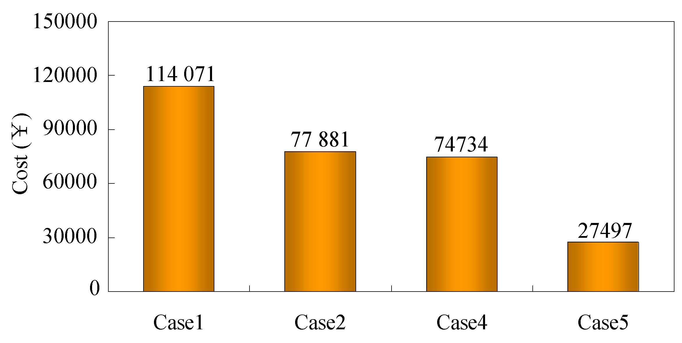
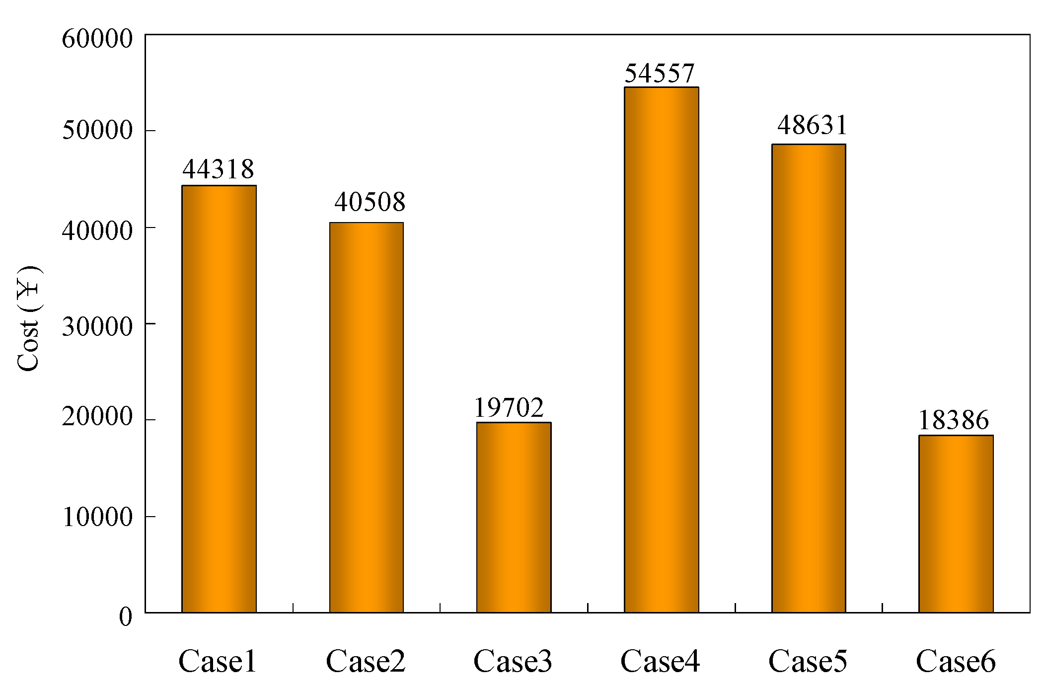
4.2. Results and Discussion

In Case 1, 2, 4 and 5, seawater-pumped storage station did not participate in the optimal scheduling. Hence, Case 3 and 6 are chosen as the benchmark. GAMS is used to calculate the power output of seawater-pumped storage station, based on the output of GAMS and Equation (1), the equivalent SOC of seawater-pumped storage station can be further calculated. Corresponding figures of these parameters under different cases are shown in Figure 7 and Figure 8, respectively.
The optimal state variables of interruptible loads in Case 3 are listed in Table 4, where 0 denotes the interruption. In addition, the name of interruptible load x is represented by the abbreviation of ILx in this table. As there is no interruption happened in Case 6, the corresponding states of interruptible load under this case are not given in the study.
Figure 7 and Figure 8 suggest that the seawater-pumped storage station would work in pumping mode if the power output of renewable energy is high or the load level of microgrid is low. On the contrary, if the load level is high or the power output of renewable energy is low, it would release the electricity that stored before. Thus, the load curve of experimental microgrid would become flatter. In addition, the fluctuation of power output and equivalent SOC curve is bigger in summer (Figure 7a and Figure 8a) when compared with winter (Figure 7b and Figure 8b), which means that the seawater-pumped storage station could adjust its power out according to the variety of load curve. In addition, the result in Figure 8 also shows that the equivalent SOC of seawater-pumped storage station meets the upper and lower bound constraints, which means that the pumped storage station still has the ability for further adjusting process.
The power demand of interruptible loads is fully satisfied in Case 6—and according to Table 4— only in some special periods of Case 3 that the interruptible loads were cut. The reason of the interruption happened is that the power demand is low in these period, if the diesel generators is called, the compensation fees of interruptible load could not offset the cost of diesel generators and the economy of proposed microgrid would be affected. In the meantime, it is worth mention that the seawater-pumped storage station is working in the pumping mode during these special periods in Case 3, which means that the seawater-pumped storage station could arrange its working status reasonably to ensure the power supply of rigid load in the future and avoid the costly compensation fees to enhance the economy of proposed island microgrid.
The power output of diesel generators in Case 1 to 5 are shown in Figure 9, as no diesel generator is called in Case 6, the corresponding figure is removed. In these figures, the power output of diesel generator in Case 2 (Figure 9b) is smaller than Case 1 (Figure 9a), and the diesel generator was called only in the periods of 10, 14 and 15 in Case 3 (Figure 9c) which takes seawater-pumped storage station into consideration. Accordingly, the scheduling model proposed in this study could reduce the costs of diesel generator effectively in summer.
Due to the decline of wind and photovoltaic in winter, the power output of diesel generators increased remarkably in Case 4 and 5 (Figure 9d,e). However, these diesel generators were abandoned in Case 6, which mean that the seawater-pumped storage station could further reduce the total costs of diesel generator in the seasons with less renewable energy resources, lower load demand and smaller load fluctuation.
Figure 10 and Figure 11 show the rigid load and renewable energy curtailments under different cases, respectively. The compensation fee of rigid load curtailment is presented in Figure 12, which can be calculated by summing the interrupted power of the rigid load at each time period and multiplying the result with the unit rigid load compensation cost. Since there are no curtailments of renewable energy and rigid load in Case 3 and 6, Figure 10, Figure 11 and Figure 12 do not give the corresponding figures.
The operation and maintenance costs of proposed island microgrid without rigid load compensation is given in Figure 13, which is related to the rest part of the objective function in Equation (17) except the rigid load compensation cost, and can be calculated by using the output result of GAMS minus the data of Figure 12. Comparing with the aforementioned figures and tables, the conclusion can be drawn that the model proposed in this study could reduce a large amount of renewable energy and rigid load curtailments with efficiency. Especially in Case 3 and 6, where the power output of renewable energy is fully utilized while the rigid loads remain the same. Thus, the power supply reliability of proposed island microgrid is improved accordingly both in summer and winter.
Furthermore, due to the costly compensation fee of rigid loads, as well as the costs of diesel generators, the operation cost of proposed microgrid would be expensive. However, by introducing seawater-pumped storage station, the curtailments of rigid loads and renewable energy were reduced, and the expense growth of island microgrid would become slower. Hence, the scheduling model proposed in this study could reduce the total operation and maintenance costs of island microgrid system obviously.

5. Conclusions

The optimal scheduling of island microgrids with seawater-pumped storage stations and renewable energy is studied in this study, in which the power supply is fulfilled by the power output of renewable energy and diesel generators. By adding interruptible loads and seawater-pumped storage stations into the power regulation process, the load curve flattens and an optimal scheduling method is accordingly established. To verify the validity of proposed model and method, simulation verification under three different conditions in two typical seasons was carried out.
Simulation results show that the participation of interruptible loads and seawater-pumped storage stations in dispatching could reduce the operation and maintenance costs of microgrids—as well as the curtailments of renewable energy and rigid loads. Particularly, with the participation of seawater-pumped storage station, rigid loads would not be cut during the dispatching periods, so the power supply reliability of island microgrid is improved obviously. In addition, the equivalent SOC of seawater-pumped storage station meets the upper and lower bound constraints simultaneously, which means that the seawater-pumped storage station could satisfy the power regulation of proposed island microgrid in the future without expansion. In summary, the optimal scheduling model and method proposed in this study could improve the reliability and economy of island microgrid system both in summer and winter remarkably.

Author Contributions

Conceptualization, N.L. and Q.S.; methodology, N.L.; software, N.L. and P.L.; validation, N.L., P.L., Q.S. and L.L.; formal analysis, N.L. and P.L.; investigation, N.L., P.L. and L.L.; resources, N.L. and Z.L.; data curation, N.L. and P.L.; writing—original draft preparation, P.L.; writing—review and editing, N.L., P.L., Z.L., Q.S. and L.L.; visualization, N.L. and P.L.; supervision, N.L. and Z.L.; project administration, N.L. and Z.L.; funding acquisition, N.L. and Z.L. All authors have read and agreed to the published version of the manuscript.

Funding

This research was funded by the Yunnan Human Resources Training Foundation of China, Grant Number KKSY201904013.

Conflicts of Interest

The authors declare no conflict of interest.

References

  1. Kwon, S.; Won, W.; Kim, J. A superstructure model of an isolated power supply system using renewable energy: Development and application to Jeju Island, Korea. Renew. Energy 2016, 97, 177–188. [Google Scholar] [CrossRef]
  2. Zhang, Z.; Wang, Z.; Chen, Z.; Wang, G.; Shen, N.; Guo, C. Study on Grid-Connected Strategy of Distribution Network with High Hydropower Penetration Rate in Isolated Operation. Processes 2019, 7, 328. [Google Scholar] [CrossRef] [Green Version]
  3. Chen, H.; Xuan, P.; Wang, Y.; Jin, X. Key Technologies for Integration of Multitype Renewable Energy Sources—Research on Multi-Timeframe Robust Scheduling/Dispatch. IEEE Trans. Smart Grid 2017, 7, 471–480. [Google Scholar] [CrossRef]
  4. Kaldellis, J.K.; Kavadias, K.; Zafirakis, D. The role of hydrogen-based energy storage in the support of large-scale wind energy integration in island grids. Int. J. Sol. Energy 2015, 34, 188–201. [Google Scholar] [CrossRef]
  5. Park, E.; Yoo, K.; Ohm, J.; Kwon, S. Case study: Renewable electricity generation systems on Geoje Island in South Korea. J. Renew. Sustain. Energy 2016, 8, 151–164. [Google Scholar] [CrossRef]
  6. Sheng, L.; Zhou, Z.; Charpentier, J.F.; Benbouzid, M.E.H. Stand-alone island daily power management using a tidal turbine farm and an ocean compressed air energy storage system. Renew. Energy 2017, 103, 286–294. [Google Scholar] [CrossRef] [Green Version]
  7. Notton, G.; Mitrushi, D.; Stoyanov, L.; Berberi, P. Operation of a photovoltaic-wind plant with a hydro pumping-storage for electricity peak-shaving in an island context. Sol. Energy 2017, 157, 20–34. [Google Scholar] [CrossRef]
  8. Koritarov, V.; Veselka, T.D.; Gasper, J.; Bethke, B.M.; Botterud, A.; Wang, J.; Mahalik, M.; Zhou, Z.; Milostan, C.; Feltes, J. Modeling and Analysis of Value of Advanced Pumped Storage Hydropower in the United States. Science 2014, 246, 25–31. [Google Scholar]
  9. Papaefthymiou, S.V.; Papathanassiou, S.A. Optimum sizing of wind-pumped-storage hybrid power stations inisland systems. Renew. Energy 2014, 64, 187–196. [Google Scholar] [CrossRef]
  10. Canales, F.A.; Beluco, A.; Carlos, M. A comparative study of a wind hydro hybrid system with water storage capacity: Conventional reservoir or pumped storage plant? J. Energy Storage 2015, 4, 96–105. [Google Scholar] [CrossRef]
  11. Zhao, G.; Ren, J. Research on an Output Power Model of a Doubly-Fed Variable-Speed Pumped Storage Unit with Switching Process. Appl. Sci. 2019, 9, 3368. [Google Scholar] [CrossRef] [Green Version]
  12. Pina, A.; Ioakimidis, C.S.; Ferrao, P. Economic modeling of a seawater pumped-storage system in the context of São Miguel. In Proceedings of the 2008 IEEE International Conference on Sustainable Energy Technologies, Singapore, 24–27 November 2008. [Google Scholar]
  13. Hiratsuka, A.; Arai, T.; Yoshimura, T. Seawater pumped-storage power plant in Okinawa island, Japan. Eng. Geol. 1993, 35, 237–246. [Google Scholar] [CrossRef]
  14. Katsaprakakis, D.; Christakis, D.; Stefanakis, I.; Spanos, P.; Stefanakis, N. Technical details regarding the design, the construction and the operation of seawater pumped storage systems. Energy 2013, 55, 619–630. [Google Scholar] [CrossRef]
  15. Cao, Y.; Wang, K.; Shi, W.; Li, G. Study on dispatching strategies of a wind-solar-seawater pumped storage hybrid power system. Power Syst. Prot. Control 2018, 46, 16–23. [Google Scholar]
  16. Liang, N.; Deng, C.; Chen, Y.; Yao, W.; Li, D.; Chen, M.; Peng, P. Two-Stage coordinate optimal scheduling of seawater pumped storage in active distribution networks. Sustainability 2018, 10, 2014. [Google Scholar] [CrossRef] [Green Version]
  17. Fan, L.; Wang, K.; Li, G.; Shi, W.; Liu, X. An optimization dispatch study of micro grid with seawater pumped storage plant in isolated island. Power Syst. Technol. 2016, 40, 382–386. [Google Scholar]
  18. Liu, Z. Application of Seawater Pumped Storage Technology in Island Power Supply. Power Energy 2017, 38, 593–597. [Google Scholar]
  19. Qian, G. Brief Introduction of Chinese Seawater Pumped Storage Power Station’s Resources. Hydropower Pumped Storage 2017, 3, 1–6. [Google Scholar]
  20. Zhang, H.; Wu, S.; Rui, D.; Zhang, D. Study on Selection and Development of Demonstration Project of Seawater Pumped Storage Power Station in China. Hydropower Pumped Storage 2017, 3, 7–10. [Google Scholar]
  21. Portero, U.; Velázquez, S.; Carta, J.A. Sizing of a wind-hydro system using a reversible hydraulic facility with seawater. A case study in the Canary Islands. Energy Convers. Manag. 2015, 106, 1251–1263. [Google Scholar] [CrossRef]
  22. Manfrida, G.; Secchi, R. Seawater pumping as an electricity storage solution for photovoltaic energy systems. Energy 2014, 69, 470–484. [Google Scholar] [CrossRef]
  23. Katsaprakakis, D.A.; Christakis, D.G. Seawater pumped storage systems and offshore wind parks in islands with low onshore wind potential. A fundamental case study. Energy 2014, 66, 470–486. [Google Scholar] [CrossRef]
  24. Hessami, M.A.; Bowly, D.R. Economic feasibility and optimisation of an energy storage system for Portland Wind Farm (Victoria, Australia). Appl. Energy 2011, 88, 2755–2763. [Google Scholar] [CrossRef]
  25. Mclean, E.; Kearney, D. An Evaluation of Seawater Pumped Hydro Storage for Regulating the Export of Renewable Energy to the National Grid. Energy Procedia 2014, 46, 152–160. [Google Scholar] [CrossRef] [Green Version]
  26. Bowden, G.J.; Barker, P.R.; Shestopal, V.O.; Twidell, J.W. Weibull distribution function and wind power statistics. Wind Eng. 1983, 7, 85–98. [Google Scholar]
  27. Yan, G.; Wang, Z.; Li, J.; Feng, L. Research on output power fluctuation characteristics of the clustering photovoltaic-wind joint power generation system based on continuous output analysis. In Proceedings of the 2014 International Conference on Power System Technology (POWERCON), Chengdu, China, 20–22 October 2014. [Google Scholar]
  28. Jon, L.; Sven, L. Mixed Integer Nonlinear Programming. International 2001, 9, 373–395. [Google Scholar]
  29. GAMS. Available online: https://www.gams.com/ (accessed on 5 May 2020).
Figure 1. Framework of proposed island microgrid system.
Processes 08 00737 g001
Figure 2. Proposed optimization framework.
Processes 08 00737 g002
Figure 3. Flowchart of the solving process.
Processes 08 00737 g003
Figure 4. Distribution network of island microgrid.
Processes 08 00737 g004
Figure 5. Load curve of the experimental microgrid. (a) load curve of the experimental microgrid in summer; (b) load curve of the experimental microgrid in winter.
Processes 08 00737 g005
Figure 6. Power-output prediction of renewable energy resources. (a) power-output prediction of renewable energy resources in summer; (b) power-output prediction of renewable energy resources in winter.
Processes 08 00737 g006
Figure 7. Power output of seawater-pumped storage station. (a) Power output of seawater-pumped storage station in summer; (b) power output of seawater-pumped storage station in winter.
Processes 08 00737 g007
Figure 8. Equivalent state-of-charge (SOC) of seawater-pumped storage station. (a) Equivalent SOC of seawater-pumped storage station in summer; (b) equivalent SOC of seawater-pumped storage station in winter.
Processes 08 00737 g008
Figure 9. Power output of diesel generator under different cases. (a) Power output of diesel generator in Case 1; (b) power output of diesel generator in Case 2; (c) power output of diesel generator in Case 3; (d) power output of diesel generator in Case 4; (e) power output of diesel generator in Case 5.x
Processes 08 00737 g009
Figure 10. Rigid load curtailment under different cases. (a) Rigid load curtailment in Case 1; (b) rigid load curtailment in Case 2; (c) rigid load curtailment in Case 4; (d) rigid load curtailment in Case 5.
Processes 08 00737 g010aProcesses 08 00737 g010b
Figure 11. Renewable energy curtailments under different cases. (a) Renewable energy curtailments in Case 1; (b) renewable energy curtailments in Case 2; (c) renewable energy curtailments in Case 4; (d) renewable energy curtailments in Case 5.
Processes 08 00737 g011
Figure 12. Compensation fee of rigid load curtailment.
Processes 08 00737 g012
Figure 13. Operation and maintenance costs of island microgrid without rigid load compensation.
Processes 08 00737 g013
Table 1. Parameters of seawater-pumped storage station.
P g e n max / P p u m p max (kW)kgen/kpumpCgen/Cpump (¥) λ g e n r u n / λ p u m p r u n (¥/kW) λ s e a c o (¥/kW)
Generating mode40000.923000.150.05
Pumping mode40000.784000.15
Table 2. Parameters of diesel generator.
abc P D E min (kW) P D E max (kW)Con (¥)Coff (¥)NDE λ D E r u n (¥/kW)
0.00150.3482285050050540.1
Table 3. Parameters of wind turbine and photovoltaic.
vc (m/s)vr (m/s)vf (m/s)awbwcwPwr (kW) λ w r u n (¥/kW)ηpv λ p v r u n (¥/kW)
3.517.5183.4−129.21300.120.90.1
Table 4. Optimal state variables of interruptible loads of Case 3.
PeriodIL1
(Node1)
IL2
(Node5)
IL3
(Node7)
IL4
(Node9)
PeriodIL1
(Node1)
IL2
(Node5)
IL3
(Node7)
IL4
(Node9)
11111131111
20111141111
30111151111
40110161111
51111171111
61111181111
71111191111
81111200111
91111210111
101111220111
111111231111
121111241111

