Abstract
Zinc-air batteries (ZABs) offer a sustainable and safe pathway to low-cost energy storage. Recent research shows that thermally-sintered porous Zn electrodes with a three-dimensional network structure can enhance the performance and lifetime of ZABs, but they are expensive and energy-intensive to manufacture. In this work, monolithic porous Zn electrodes fabricated through an efficient cold sintering process (CSP) were studied for rechargeable ZABs. Electrochemical studies and extended charge-discharge cycling show good Zn utilization with no observable performance degradation when compared to Zn foil. Post-mortem analysis after 152 h of cycling reveals that the cold-sintered electrodes retain their original structure. A techno-economic assessment of the cold sintering process confirms significant reductions in both the time and energy required to manufacture Zn electrodes compared to a comparable thermal sintering process.
1. Introduction
Electrically rechargeable zinc-air batteries (ZABs) are a safe, sustainable, and affordable solution for large-scale renewable energy storage [1]. ZABs combine a metallic Zn anode with an air-breathing cathode and an aqueous alkaline electrolyte to achieve a very high theoretical specific energy (1090 ) and energy density (6100 ). Unlike Li-ion batteries, which can pose a severe fire hazard, ZABs employ a non-flammable aqueous electrolyte and are inherently safe [2]. Furthermore, Zn metal is one of the most abundant battery materials on Earth [3]. These characteristics have made single-use ZABs the battery of choice for lightweight electronics like hearing aids for many decades. Today, the need for safe and energy-dense grid-scale storage is driving renewed interest in the technology. Start-up companies are beginning to commercialize rechargeable ZABs for stationary energy storage, and they are being researched for potential applications in electric vehicles [4] and flexible electronics [5].
Most ZABs use a concentrated alkaline electrolyte (e.g., 30 wt% KOH) due to the superior ionic conductivity and support for fast reaction kinetics [6]. The ZAB half-cell reactions and standard equilibrium potentials in alkaline media are:
When the cell is discharged, O2 from the air is reduced to form OH− ions in the cathode. In the anode, the Zn metal is oxidized to form Zn(OH)42− (zincate). When the concentration of zincate in the electrolyte surpasses the solubility limit, solid products dominated by ZnO precipitate on or near the Zn electrode:
The precipitation of ZnO allows the cell to achieve a stable working point [7], with the overall reaction and standard equilibrium open-circuit voltage (OCV):
In ZABs with concentrated alkaline electrolytes, the equilibrium open-circuit voltage increases to circa 1.65 as described by the Nernst equation.
ZABs are very successful as single-use (primary) batteries, but their use in electrically rechargeable (secondary) batteries has traditionally been limited by several factors linked to the design of the Zn electrode [8]. Firstly, ZnO is moderately soluble in alkaline electrolytes. The solubility of ZnO is helpful in limiting the effects of passive film formation on the Zn electrode surface but harmful for the long-term performance of the electrode. When the Zn electrode is discharged, Zn(OH)42− ions can diffuse some distance through the electrolyte before they precipitate as ZnO. This has the effect that Zn which dissolves in one region of the electrode may precipitate as ZnO in a different region of the electrode. Over many charge-discharge cycles, this leads to the redistribution of material and the densification of the electrode. An additional challenge is that the molar volume of ZnO is roughly 60% larger than Zn metal. As a result, the volume of the electrode expands when the cell is discharged and contracts when the cell is charged. This effect further exacerbates the cycling stability of Zn electrodes. Finally, when recharged in aqueous alkaline electrolytes, Zn metal tends to form dendritic or mossy deposits on the electrode surface. If these deposits become too large, they can create an internal short-circuit and cause the cell to stop working. Recent research highlights Zn electrode design improvement as a necessary focus to bring next-generation ZABs into the mainstream [9,10].
The design of Zn electrodes for battery applications can be divided into three categories: foil, paste, or structured electrodes. Throughout the early to mid-twentieth century, Zn foil electrodes were widely used for commercial primary Zn-based batteries due to the ease with which they can be manufactured [11]. In spite of this simplicity, the performance of a Zn foil electrode is limited by its low surface area, susceptibility to ZnO layer passivation, and shape change during electrical recharging. Although foils are still used as electrodes in research battery cells, commercial Zn-based batteries have abandoned foils in favor of porous Zn paste electrodes [12,13]. Paste electrodes consist of powdered Zn metal particles combined with electrolyte and a binder [14,15]. Such electrodes are suitable for creating high-energy cells with good Zn utilization and discharging rate. Paste electrodes are the industry standard electrode in primary ZABs. Unfortunately, the electrical rechargeability of paste electrodes is poor, partly due to the loss of contact between metal particles as the electrode expands and contracts in volume. In contrast, structured electrodes that retain a conductive network can improve the cycle life of ZABs [10].
The use of thermal sintering processes (TSP) to create structured microporous Zn sponge monoliths have been studied since at least the 1960s [16,17,18,19]. The recently renewed and growing interest in secondary Zn-based batteries has led to a revival of the technology over the last decade [20,21,22,23,24,25,26,27]. In particular, research conducted by the United States Naval Research Laboratory demonstrates that 3D Zn sponge electrodes can retain their shape after deep discharge [22] and improve the cycle life of secondary Zn-based batteries [21]. It is proposed that the reduced shape change is linked to the effective management of ZnO precipitation. When sponge-like electrodes are discharged, the small pores quickly become saturated with zincate, and ZnO precipitates on the pore walls [21]. This acts to trap zinc in the pores and reduce the shape change of the electrode. Furthermore, the electrode forms a single conductive structure, which minimizes the loss of electrically isolated Zn particles due to volume expansion and contraction.
The thermal sintering process that is typically used to convert Zn metal powders into sponge electrodes [20,21,28] is effective, but it is also energy-intensive and time-consuming. As an alternative, the cold sintering process (CSP) uses aqueous chemical solutions to dissolve the passivation layer covering the metal surface and facilitate the self-exchange of metal atoms. Aqueous acetic acid solutions have been shown to cold sinter Zn powders in the production of conductive inks [29]. The use of the CSP to prepare structured Zn electrodes for battery applications has not yet been investigated. By reducing the time and energy required to sinter the electrodes, the CSP could be a promising process to support the cost-effective production of structured microporous Zn electrodes.
Figure 1 shows a schematic illustration of the CSP. Initially, the Zn powder particles are covered by a passivation layer consisting primarily of ZnO and Zn(OH)2. Zinc oxides, hydroxides, and carbonates are known to be soluble in acidic solutions [30]. When the acetic acid solution is added to the Zn powder, the passivation layer dissolves and exposes the surface of the metal. The dissolution of the passivation layer also releases Zn2+ into the solution, which is chelated by acetate (OAc−):
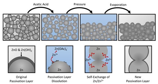
Figure 1.
Schematic representation of the cold sintering process. Zn particles are initially covered by a passivation layer consisting primarily of ZnO and Zn(OH)2. Soaking the Zn particles in a solution of acetic acid dissolves the passivation layer and chelates the resulting Zn2+ ions. Applying an external pressure facilitates the formation of contact interfaces between the Zn particles, which are sintered via the self-exhcange between Zn/Zn2+. The solution is evaporated and a new passivation layer forms over the surface of the sintered electrode.
The chelation of Zn2+ in the solution by acetate disturbs the Zn/Zn2+ equilibrium and drives the self-exchange reaction at the Zn/H2O interface [29]. External pressure is then applied to compress the powder and create new interfaces between the Zn particles. The rearrangement of the Zn surfaces enhances the formation of larger particles that are more energetically favored than the smaller powder particles. As the solution evaporates, it becomes saturated with Zn2+, and a new passivation layer forms over the surfaces. The resulting sintered structure is washed to remove dried deposits of zinc acetate.
This process can be further understood by examining the Pourbaix diagrams for Zn in solutions without acetate and with acetate, as shown in Figure 2. In solutions containing no acetate and 0.01 M total dissolved Zn (Figure 2a), the passivation film comprising ZnO and Zn(OH)2 is stable in the near-neutral domain (circa pH 7). Below pH 7, the passivation film is soluble, and dissolved zinc exists primarily as Zn2+ ions. In a solution containing 13.87 M of total dissolved acetate and 0.01 M total dissolved Zn (Figure 2b), the passivation film is soluble in both the acidic and near-neutral pH domains, and the dissolved zinc exists primarily as a complex with acetate (Zn(OAc)3−). The chelation of free Zn2+ ions by acetate depresses the equilibrium potential of the Zn/Zn2+ reaction, as described by the Nernst equation. When the solution is saturated with dissolved Zn (Figure 2c), the solubility of the passivation layer approaches its original limit around pH 6 and the equilibrium potential of the Zn/Zn2+ reaction rises due to the higher concentration of free Zn2+. A description of the thermodynamic model used to calculate the Pourbaix diagrams is given in the Supplementary Materials [31,32,33,34].
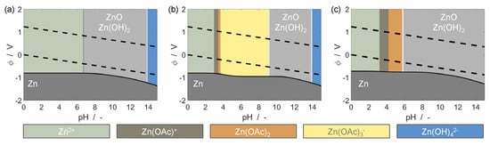
Figure 2.
Pourbaix diagrams of Zn in simplified aqueous solutions containing (a) no acetate, and 0.01 M total dissolved Zn, (b) 13.87 M total dissolved acetate, and 0.01 M total dissolved zinc, and (c) 13.87 M total dissolved acetate, and 6.935 M total dissolved zinc. Dashed lines indicate the electrochemical stability window of water.
Cold sintering of Zn metal powders using organic acids like acetic acid could offer a simple and effective process to manufacture microporous Zn electrodes. In the following section, the physical and electrochemical properties of Zn electrodes manufactured via the CSP are investigated.
2. Results
The physical and electrochemical characteristics of Zn electrodes manufactured according to the cold sintering procedure outlined in Section 4 were evaluated. First, the as-received Zn powder and the resulting cold-sintered electrode were characterized using scanning electron microscope (SEM) coupled with energy-dispersive X-ray spectroscopy (EDS). Additionally, x-ray diffraction (XRD) measurements of the fresh and cycled cold-sintered electrodes are presented. Porosimetry data of the fresh cold-sintered Zn electrode is provided in the Supplementary Materials. The electrochemical performance of the cold-sintered Zn electrodes were evaluated in a Zn-air battery (ZAB) configuration and compared with a simple Zn foil electrode.
2.1. Physical Characterization
Figure 3 presents the bulk morphology of a cross-section of a cold-sintered Zn monolith with corresponding EDS maps for zinc and oxygen. The cross-sectional backscattered electron (Figure 3a) and secondary electron (Figure 3d) images show that after reaction with acetic acid, the resulting porous monolith exhibits considerable sintering with clear evidence of zinc particle necking and coalescence. The oxygen and zinc EDS maps, shown in Figure 3b,c respectively, indicate that the surfaces of the as-sintered Zn particles are covered by an oxide layer. The pore size distribution in the fresh cold-sintered Zn electrode was investigated using mercury intrusion porosimetry. The results indicate that the majority of the pores have a diameter between 50 to 2 , and a porosity of circa 27.5% was obtained for the Zn electrode. An SEM micrograph of the initial Zn powder and the obtained pore-size distribution of the resulting cold-sintered electrode are shown in Figures S1 and S2 of the Supplementary Materials.
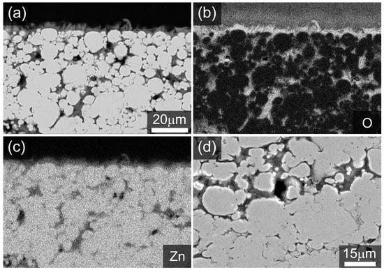
Figure 3.
Polished cross-section of an as-made Zn monolith after reaction with acetic acid showing (a) backscattered electron (BSE) image with associated EDS maps: (b) O element distribution, (c) Zn element distribution. (d) Secondary electron image in the sample bulk. Note that the sample is embedded in epoxy resin.
The presence of oxidized zinc phases was further investigated using XRD analysis, shown in Figure 4. From the XRD data, a crystalline phase of Zn(CH3CO2)2·2H2O (zinc acetate dihydrate) was identified via reference to ICDD PDF4+ database [35] pattern 00-033-1464, though a strong mismatch in peak intensities was observed due to a high degree of particle anisotropy and orientation. This can be observed visually in the SEM images in Figure 3 and Figure S3. The effect was too complex to adequately model in a full structure refinement. To confirm the presence of the phase, a structureless Pawley-type refinement was performed to determine the unit cell parameters. The refined values (see Figure 4) compare well with literature values [36] of a = 14.394 Å, b = 5.330 Å, c = 10.962 Å, = 99.88. In addition to the zinc acetate dihydrate phase, a broad single peak can be observed at circa 6.3 2, with very weak peaks suggested between 10 and 30 2. This is a typical motif for a layered hydroxide phase, and the observed d-spacing of circa 13.9 Å for the (001) diffraction index is in good accord with that reported for layered basic zinc acetate (Zn5(OH)8(CH3COO)2·2H2O) [37]. The observed particle morphology (Figure S3) is also very similar to that reported in Ref. [37]. This phase was not included in the diffraction data fitting due to the presence of only one clear diffraction line in the data.
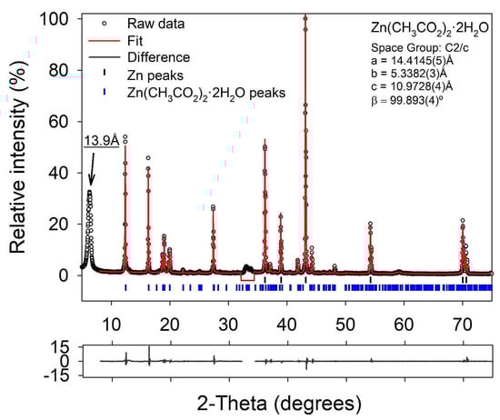
Figure 4.
Fitted X-ray diffraction pattern of an as-made porous Zn monolith before cycling. The Zn phase was fitted using a full structure model whilst the Zn(CH3CO2)2·2H2O phase was fitted using a structureless Pawley-type fitting. Fitted unit cell parameters for Zn(CH3CO2)2·2H2O are inset. Due to peak overlaps a region from 32.2 to 34.42-theta was excluded from fitting.
Figure 5 shows SEM images of Zn electrode cross-sections after electrochemical characterization in a ZAB, with accompanying X-ray diffractograms for the same samples presented in Figure 6. Following a single complete discharge of the ZAB, the growth of an oxide phase is clearly observable in Figure 5a, and the X-ray diffraction data confirms the composition at the surface to be predominantly ZnO (Figure 6a). After 152 h of ZAB cycling, Figure 5b shows that the electrode microstructure was retained. XRD analysis of this sample (Figure 6b) confirmed a much higher fraction of metallic Zn, but also identified the presence of the - [38] and - [39] forms of Zn(OH)2 in addition to some remaining ZnO. This is expected as data were collected after a partial charge step. For comparison, the X-ray diffractograms of the pure Zn powder and Zn foil are presented in Figure S4.
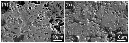
Figure 5.
SEM micrographs of the cold-sintered porous Zn electrodes after (a) full discharge and (b) 152 h of cycling ending on a charge.
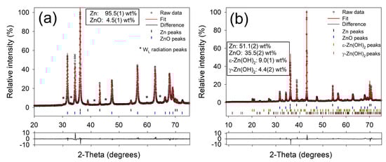
Figure 6.
Fitted X-ray diffractograms of (a) a cold-sintered porous Zn electrode after discharge (corresponding to the electrode shown in Figure 5) (b) a cold-sintered porous Zn electrode after 152 h of ZAB cycling, finishing on a charge step.
2.2. Electrochemical Characterization
Figure 7 shows the electrochemical performance of the cold-sintered Zn electrode evaluated in an alkaline ZAB configuration as described in Section 4. Figure 7a shows the galvanostatic discharge of the ZAB at 0.5 to a cut-off voltage of 0.65 . The OCV of the ZAB is 1.5 . At the start of discharging the cell, the voltage drops to circa 1.05 and quickly recovers to circa 1.2 as the cell obtains a stable working point. This drop and recovery occurs much faster than the characteristic cell voltage dip for ZnO nucleation observed in other studies [7,21]. As the Zn electrode is converted, the cell maintains a stable voltage above 1.15 for most of the discharge process before a sharp drop-off around 500 . The abrupt drop in the cell voltage is characteristic of Zn electrode passivation by the precipitated ZnO layer. The cut-off voltage is reached at 506 , which is 61.7% of the theoretical capacity of Zn.
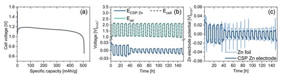
Figure 7.
Results of the electrochemical characterization tests, showing (a) voltage of a ZAB cell galvanostatically discharged to a cutoff voltage of 0.65 , (b) cell voltage and electrode potentials for a ZAB over 152 h, and (c) potential of the cold-sintered Zn electrode compared with the potential a Zn foil electrode cycled under the same conditions.
Figure 7b shows the full-cell cycling performance of an alkaline ZAB with the cold-sintered Zn electrode. The ZAB is discharged at 1.0 for 4 and subsequently charged under the same conditions. Cycling is stopped after 152 . The figure shows the cell voltage along with the half-cell potentials of the bifunctional air electrode and Zn electrode. It is well-known that the kinetics of the oxygen reduction reaction (ORR) and oxygen evolution reaction (OER) are very sluggish, and the resulting overpotentials in the bifunctional air electrode contribute the most to the magnitude of the cell voltage. In comparison, the overpotential of the Zn electrode is much smaller. The cell potential is quite stable with a voltage difference of circa 1.1 between the charge and discharge voltage through most part of the tests (Figure S5), yielding an average round-trip energy efficiency (RTE) of 52%. The low RTE is attributed to the sluggish ORR and OER kinetics as well as increased electrolyte resistance due to the necessity of two separators to accommodate the reference electrode. No considerable loss in the cell performance is observed during 152 of operation.
Figure 7c compares the cycling potential of the cold-sintered Zn electrode with that of a simple Zn foil. The Zn foil shows an average overpotential of circa 15 during cycling with an average coulombic efficiency for the Zn stripping/deposition process of 84%. Sharp voltage spikes at the start of charging and the end of discharging are observed during the first 90 h of operation. The voltage spikes are linked to the initial low surface area of the Zn foil compared to the higher surface area of the electrodeposited porous Zn morphology during cycling. On the other hand, the cold-sintered Zn electrode shows about 18 average overpotential during the first four cycles, which then is reduced to less than 10 and continued at this value till the end of the test with an average coulombic efficiency of 95%. The higher overpotential in the cold-sintered electrode over the first few cycles can be attributed to the initial formation of a precipitated ZnO phase and the stabilization of the Zn-electrolyte interface. The absence of voltage spikes and voltage transients during cycling are explained by the higher active Zn surface area inherent to the cold-sintered electrode.
3. Discussion
3.1. Performance Analysis
The galvanostatic discharge test (Figure 7a) shows that an alkaline ZAB using the cold-sintered Zn electrode can achieve single discharge performance comparable to that reported in existing studies [10]. The Zn utilization of 61.7% is reasonable, but it can still be improved through optimization of the Zn electrode manufacturing process. The reduced utilization of Zn is likely due to blockage of the micropores with ZnO. The Zn electrode in a ZAB does not dissolve homogeneously. Rather, dissolution begins at the front interface with the separator and moves towards the back of the electrode [13]. As a result, if the pores near the front of the electrode become completely filled with ZnO, then the electrode becomes passivated and the active Zn metal at the back of the electrode remains unused. Indeed, Figure 5a shows that after full discharge, the pore space in the electrode is almost completely filled with ZnO. To address this challenge, the cold sintering process can be optimized to give a more appropriate electrode porosity and pore-space distribution. This is a topic for further research.
The ZAB cycling performance obtained using the cold-sintered Zn electrode (Figure 7b) confirms the viable reversibility of the electrode and demonstrates a reasonable improvement over the Zn foil electrode (Figure 7c). After 152 of operation, the cold-sintered Zn electrode shows no obvious signs of degradation and the SEM micrograph of the cycled electrode (Figure 5b) confirms that the porous structure is retained. More long-term analysis is needed to quantify the complete cycle life of the cold-sintered electrodes for accurate comparison with literature benchmarks [10]. This is a topic for further research.
3.2. Techno-Economic Analysis
One of the main goals for implementing the CSP is to reduce the time, energy, and cost required to manufacture monolithic porous Zn electrodes. Here we compare the thermal sintering process described in Ref [20] with the cold sintering process described in this work. The techno-economic analysis presented in this section evaluates the different sintering methods as they are described in Ref. [20] and Section 4 for lab-scale batch production. Energy and power requirements are calculated assuming ideal conditions to remove the influence of variations in the type and efficiency of equipment used. More information is available in the Supplementary Materials.
Table 1 lists the time, power, and energy requirements to produce 1 of Zn electrodes using the thermal sintering process. The main driver of the processing time is the resting period after mixing the Zn slurry (1440 ) followed by the time required for the heat treatment (558.75 ). The energy required to heat and cool the electrodes during the heat treatment (308.46 ) is the main contributor to the energy consumption of the thermal sintering process.

Table 1.
Calculated thermal sintering time, power, and energy consumption for preparation of 1 Zn electrodes, according to the process described in Ref. [20].
Table 2 lists the time, power, and energy requirements to produce 1 of Zn electrodes using the cold sintering process. The largest contributor to the time requirement is the drying process, which takes place overnight (900 ). The energy requirements for the cold sintering process are very low but depend mostly on heating and cooling the Zn electrode during the drying process (10.60 ).
Table 2.
Calculated cold sintering time, power, and energy consumption for preparation of 1 Zn electrodes.
A comparison of the time, energy, and material costs for the thermal sintering, and cold sintering processes is shown in Table 3. The results show that the cold sintering process reduces the process time by 47.50% (15.8 ), the processing energy requirement by 96.09% (298.2 ), and materials cost by 5.4% ($10.43 ).
Table 3.
Comparison of the time, energy, and materials cost needed to manufacture monolithic Zn foam electrodes using thermal sintering and cold sintering processes.
It is important to note that the processes as compared here are lab-scale and not optimized for production. Optimized processing and scaled-up production will reduce the magnitude of the time, energy, and cost requirements, but the relative differences between optimized thermal and cold sintering processes are likely to remain.
4. Materials and Methods
Porous zinc electrodes were prepared by cold sintering of Zn powder (>95%, Sigma Aldrich). 10 of Zn powder was mixed with ethanol to a slurry of circa 55 wt% solid loading and transferred to stainless steel pressing dies. After a 2-h drying at ambient temperature, a copper mesh (60 mesh, >99.9%, Alfa Aesar), cut to fit the dies, was placed on top of the dried slurry. Slightly diluted acetic acid (80 vol%, >99.9%, SAFC) was added in a weight ratio of 1:10 to the Zn piece before uni-axial pressing at 6 for two minutes. The as-prepared electrodes were thoroughly washed with deionized water and dried at 60 overnight before physical and electrochemical characterization. The average thickness of the produced Zn electrode is about 1.45 mm.
The porosity and the pore-size distribution of the prepared Zn electrodes was analyzed using mercury intrusion porosimetry (AutoPore IV, Micromeritics), and a more detailed microstructure analysis was performed by scanning electron microscopy (SEM, Hitachi S-3400 N) and energy dispersive X-ray spectroscopy (EDS). For cross-section analysis, samples were embedded in epoxy resin and polished using silicon carbide and diamond polishing media down to 1 size. Phase analysis and composition of the Zn powder, fresh Zn electrode and the Zn electrode after ZAB cycling was performed by X-ray diffraction (XRD, Bruker D8 A25 DaVinci X-ray Diffractometer with CuK- radiation), with data fitted using the Bruker Topas v5 analysis software.
Specific capacity measurements were carried out in an ECC-Air-Ni (EL-Cell GmbH) test cell with Ni and Cu as current collectors for cathode and anode, respectively. NiCo2O4 (Cerpotech AS) dry mixed with PTFE and pressed on to a Ni foam was used as the bifunctional air electrode. The geometric area of the electrodes was 1.77 . Glass fiber paper saturated with 30 wt% KOH electrolyte was used as the separator. The cold-sintered porous Zn electrodes used in this work were pre-soaked in the electrolyte overnight before cell assembly and electrochemical testing. The specific capacity of the Zn electrode was evaluated by discharging the ZAB at 0.5 with a cut-off cell voltage at 0.65 V.
Full cell cycling performance was carried out in a static 25 in-house designed ZAB test cell incorporating a thin Zn foil as reference electrode in order to record the Zn electrode and bifunctional air electrode potentials individually. A glass fiber separator impregnated with 4 mL of 30 wt% KOH was used as the electrolyte, while NiCo2O4 dry mixed with PTFE and Ni powder and hot-pressed with a stainless steel mesh current collector was used as the bifunctional air electrode. Galvanostatic cycling was performed under a flow of synthetic air, with discharge and charge cycles at a current density 1 and a cycle time of 8 h.
5. Conclusions
A new, cost-effective, and environmentally friendly cold sintering process for manufacturing porous Zn electrodes for electrically rechargeable Zn-air batteries (ZABs) is reported in this work. Full cell tests using a cold-sintered porous Zn electrode in a ZAB configuration show a reasonably good Zn utilization of 61.7%. The porous Zn electrode exhibits excellent cycling performance with high reversibility for Zn deposition/stripping. Post-mortem studies after 152 h of cycling show that the Zn electrode maintains its porous structure with no evidence of significant shape or morphology change. Techno-economic analysis comparing the cold sintering process (CSP) with a comparable thermal sintering process (TSP) shows that the CSP can potentially lead to significant reductions in the time (47.50%) and energy (96.09%) required to produce porous Zn electrodes. This work presents a proof-of-concept confirming the feasibility of cold-sintered Zn electrodes is ZABs, with potential applications in stationary energy storage.
Supplementary Materials
The supplementary materials are available online at https://www.mdpi.com/2227-9717/8/5/592/s1.
Author Contributions
Conceptualization, K.J., S.C., J.R.T., P.I.D., and M.J.; methodology, K.J., C.K., and P.I.D.; software, S.C.; validation, K.J., and C.K.; formal analysis, K.J., C.K., and J.R.T.; investigation, K.J. and S.C.; resources, K.J.; data curation, K.J.; writing–original draft preparation, K.J.; writing–review and editing, J.R.T., S.C.; visualization, S.C.; supervision, K.J.; project administration, M.J.; funding acquisition, M.J. All authors have read and agreed to the published version of the manuscript.
Funding
This research was funded by EU Horizon 2020 grant number 646186 (ZAS! project).
Acknowledgments
The authors thank Norbert Wagner and Alexander Kube from the German Aerospace Center (DLR), Stuttgart for providing bifunctional air electrodes for the study.
Conflicts of Interest
The authors declare no conflict of interest. The funders had no role in the design of the study; in the collection, analyses, or interpretation of data; in the writing of the manuscript, or in the decision to publish the results.
Abbreviations
The following abbreviations are used in this manuscript:
| BSE | Backscattered electron |
| CSP | Cold sintering process |
| EDS | Energy dispersive X-ray spectroscopy |
| OAc | Acetate |
| OCV | Open circuit voltage |
| OER | Oxygen evolution reaction |
| ORR | Oxygen reduction reaction |
| PTFE | Polytetrafluoroethylene |
| RTE | Round trip efficiency |
| SE | Secondary electron |
| SEM | Scanning electron microscope |
| TSP | Thermal sintering process |
| XRD | X-ray diffraction |
| ZAB | Zinc-air battery |
References
- Gu, P.; Zheng, M.; Zhao, Q.; Xiao, X.; Xue, H.; Pang, H. Rechargeable zinc-air battery: A promising way to green energy. J. Mater. Chem. A 2017, 5, 7651–7666. [Google Scholar] [CrossRef]
- Mainar, A.R.; Iruin, E.; Colmenares, L.C.; Kvasha, A.; de Meatza, I.; Bengoechea, M.; Leonet, O.; Boyano, I.; Zhang, Z.; Blazquez, J.A. An overview of progress in electrolytes for secondary zinc-air batteries and other storage systems based on zinc. J. Energy Storage 2018, 15, 304–328. [Google Scholar] [CrossRef]
- U.S. Geological Survey. Mineral Commodity Summaries 2020; U.S. Geological Survey: Reston, VA, USA, 2020; p. 200.
- Cano, Z.P.; Banham, D.; Ye, S.; Hintennach, A.; Lu, J.; Fowler, M.; Chen, Z. Batteries and fuel cells for emerging electric vehicle markets. Nat. Energy 2018, 3, 279–289. [Google Scholar] [CrossRef]
- Park, J.; Park, M.; Nam, G.; Lee, J.S.; Cho, J. All-solid-state cable-type flexible zinc-air battery. Adv. Mater. 2015, 27, 1396–1401. [Google Scholar] [CrossRef] [PubMed]
- Mainar, A.R.; Leonet, O.; Bengoechea, M.; Boyano, I.; de Meatza, I.; Kvasha, A.; Guerfi, A.; Blazquez, J.A. Alkaline aqueous electrolytes for secondary zinc-air batteries: An overview. Int. J. Energy Res. 2016, 40, 1032–1049. [Google Scholar] [CrossRef]
- Stamm, J.; Varzi, A.; Latz, A.; Horstmann, B. Modeling nucleation and growth of zinc oxide during discharge of primary zinc-air batteries. J. Power Sources 2017, 360, 136–149. [Google Scholar] [CrossRef]
- Yi, J.; Liang, P.; Liu, X.; Wu, K.; Liu, Y.; Wang, Y.; Xia, Y.; Zhang, J. Challenges, mitigation strategies and perspectives in development of zinc-electrode materials and fabrication for rechargeable zinc-air batteries. Energy Environ. Sci. 2018, 11, 3075–3095. [Google Scholar] [CrossRef]
- Zhang, J.; Zhou, Q.; Tang, Y.; Zhang, L.; Li, Y. Zinc-air batteries: Are they ready for prime time? Chem. Sci. 2019, 10, 8924–8929. [Google Scholar] [CrossRef]
- Stock, D.; Dongmo, S.; Janek, J.; Schröder, D. Benchmarking Anode Concepts: The Future of Electrically Rechargeable Zinc-Air Batteries. ACS Energy Lett. 2019, 4, 1287–1300. [Google Scholar] [CrossRef]
- Heise, G.W.; Cahoon, N.C. Dry Cells of the Leclanche Type, 1902–1952—A Review. J. Electrochem. Soc. 1952, 99, 179C–187C. [Google Scholar] [CrossRef]
- Horn, Q.C.; Shao-Horn, Y. Morphology and Spatial Distribution of ZnO Formed in Discharged Alkaline Zn/MnO2 AA Cells. J. Electrochem. Soc. 2003, 150, A652–A658. [Google Scholar] [CrossRef]
- Arlt, T.; Schröder, D.; Krewer, U.; Manke, I. In operando monitoring of the state of charge and species distribution in zinc air batteries using X-ray tomography and model-based simulations. Phys. Chem. Chem. Phys. 2014, 16, 22273–22280. [Google Scholar] [CrossRef] [PubMed]
- Mainar, A.R.; Colmenares, L.C.; Blázquez, J.A.; Urdampilleta, I. A brief overview of secondary zinc anode development: The key of improving zinc-based energy storage systems. Int. J. Energy Res. 2017, 42, 903–918. [Google Scholar] [CrossRef]
- Schmitt, T.; Arlt, T.; Manke, I.; Latz, A.; Horstmann, B. Zinc Electrode Shape-Change in Secondary Air Batteries: A 2D Modeling Approach. J. Power Sources 2019, 432, 119–132. [Google Scholar] [CrossRef]
- Kelly, F.J.; Przybyla, F. Method of Making a Sintered Zinc Battery Anode Structure. US Patent 3,384,482, 21 May 1968. [Google Scholar]
- Himy, A. Development of Improved Zinc Electrodes for Secondary Batteries; Technical Report; NASA: Newport Beach, CA, USA, 1969.
- Arrance, F.C.; Berger, C. Process of Forming a Sintered Zinc Electrode. US Patent 3,617,592, 2 November 1971. [Google Scholar]
- Weller, R.D. Process for the Preparation of Sintered Zinc Powder Battery Electrodes. US Patent 3,663,297, 16 May 1972. [Google Scholar]
- Drillet, J.F.; Adam, M.; Barg, S.; Herter, A.; Koch, D.; Schmidt, V.M.; Wilhelm, M. Development of a novel zinc/air fuel cell with a Zn foam anode, a PVA/KOH membrane and a MnO2/SiOC-based air cathode. ECS Trans. 2010, 28, 13–24. [Google Scholar]
- Parker, J.F.; Chervin, C.N.; Nelson, E.S.; Rolison, D.R.; Long, J.W. Wiring zinc in three dimensions re-writes battery performance—Dendrite-free cycling. Energy Environ. Sci. 2014, 7, 1117–1124. [Google Scholar] [CrossRef]
- Parker, J.F.; Nelson, E.S.; Wattendorf, M.D.; Chervin, C.N.; Long, W.; Rolison, D.R. Retaining the 3D Framework of Zinc Sponge Anodes upon Deep Discharge in Zn-Air Cells. ACS Appl. Mater. Interfaces 2014, 6, 19471–19476. [Google Scholar] [CrossRef]
- Parker, J.F.; Chervin, C.N.; Pala, I.R.; Machler, M.; Burz, M.F.; Long, J.W.; Rolison, D.R. Rechargeable nickel–3D zinc batteries: An energy-dense, safer alternative to lithium-ion. Science 2017, 356, 415–418. [Google Scholar] [CrossRef]
- Stock, D.; Dongmo, S.; Walther, F.; Sann, J.; Janek, J.; Schröder, D. Homogeneous coating with anion-exchange ionomer improves the cycling stability of secondary batteries with zinc anode. ACS Appl. Mater. Interfaces 2018, 10, 8640–8648. [Google Scholar] [CrossRef]
- Liu, P.; Ling, X.; Zhong, C.; Deng, Y.; Han, X.; Hu, W. Porous Zinc Anode Design for Zn-air Chemistry. Front. Chem. 2019, 7. [Google Scholar] [CrossRef]
- Ko, J.S.; Geltmacher, A.B.; Hopkins, B.J.; Rolison, D.R.; Long, J.W.; Parker, J.F. Robust 3D Zn sponges enable high-power, energy-dense alkaline batteries. ACS Appl. Energy Mater. 2019, 2, 212–216. [Google Scholar] [CrossRef]
- Hopkins, B.J.; Sassin, M.B.; Chervin, C.N.; DeSario, P.A.; Parker, J.F.; Long, J.W.; Rolison, D.R. Fabricating architected zinc electrodes with unprecedented volumetric capacity in rechargeable alkaline cells. Energy Storage Mater. 2020, 27, 370–376. [Google Scholar] [CrossRef]
- Kränzlin, N.; Niederberger, M. Controlled fabrication of porous metals from the nanometer to the macroscopic scale. Mater. Horiz. 2015, 2, 359–377. [Google Scholar] [CrossRef]
- Lee, Y.K.; Kim, J.; Kim, Y.; Kwak, J.W.; Yoon, Y.; Rogers, J.A. Room Temperature Electrochemical Sintering of Zn Microparticles and Its Use in Printable Conducting Inks for Bioresorbable Electronics. Adv. Mater. 2017, 29, 1–8. [Google Scholar] [CrossRef]
- Pourbaix, M. Atlas of Electrochemical Equilibria in Aqueous Solutions, 2nd ed.; National Association of Corrosion Engineers: Houston, TX, USA, 1974. [Google Scholar]
- Smith, R.; Martell, A. Critical Stability Constants; Springer: New York, NY, USA, 1976; Volume 4. [Google Scholar]
- Zhang, Y.; Muhammed, M. Critical evaluation of thermodynamics of complex formation of metal ions in aqueous solutions—VI. Hydrolysis and hydroxo-complexes of Zn2+ at 298.15 K. Hydrometallurgy 2001, 60, 215–236. [Google Scholar] [CrossRef]
- Mahlendorf, F.; Fuchs, D. ZnMobil Abschlussbericht; Technical Report; Universitaet Duisburg-Essen: Duisburg-Essen, Germany, 2019. [Google Scholar]
- Albright, L.F. Albright’s Chemical Engineering Handbook; CRC Press: Boca Raton, FL, USA, 2009. [Google Scholar]
- Kabekkodu, S. (Ed.) PDF-4+ 2017 (Database); International Centre for Diffraction Data: Newtown Square, PA, USA, 2017. [Google Scholar]
- Ishioka, T.; Murata, A.; Kitagawa, Y.; Nakamura, K.T. Zinc(II) Acetate Dihydrate. Acta Crystallogr. 1997, C53, 1029–1031. [Google Scholar] [CrossRef]
- Hosono, E.; Fujihara, S.; Kimura, T.; Imai, H. Growth of layered basic zinc acetate in methanolic solutions and its pyrolytic transformation into porous zinc oxide films. J. Colloid Interface Sci. 2004, 272, 391–398. [Google Scholar] [CrossRef]
- Stahl, R.; Jung, C.; Lutz, H.; Kockelmann, W.; Jacobs, H. Kristallstrukturen und Wasserstoffbruckenbindungen bei beta-Be(OH)2 und epsilon-Zn(OH)2. Z. Anorg. Chem. 1998, 624, 1130–1136. [Google Scholar] [CrossRef]
- Christensen, A.N. The crystal structure of gamma-Zn(OH)2. Acta Chem. Scand. 1969, 23, 2016–2020. [Google Scholar] [CrossRef]
© 2020 by the authors. Licensee MDPI, Basel, Switzerland. This article is an open access article distributed under the terms and conditions of the Creative Commons Attribution (CC BY) license (http://creativecommons.org/licenses/by/4.0/).