Article

RF-ICP Thermal Plasma for Thermoplastic Waste Pyrolysis Process with High Conversion Yield and Tar Elimination

Faculty of Energy Systems and Nuclear Science, University of Ontario Institute of Technology, Oshawa, ON L1G0C5, Canada
*
Author to whom correspondence should be addressed.
Processes 2020, 8(3), 281; https://doi.org/10.3390/pr8030281
Submission received: 29 January 2020 / Revised: 24 February 2020 / Accepted: 26 February 2020 / Published: 28 February 2020

Abstract

:
This paper demonstrates an RF thermal plasma pyrolysis reaction apparatus that achieves 89 wt.% reaction conversion yield with no tar content. The demonstrated experimental apparatus consists of a 1100 W RFVII Inc. (104 Church St, Newfield, NJ 08344, United States) @ 13.56 MHz RF thermal plasma generator, a Navio matching network, intelligent feedback controller, and an 8-turn copper RF-ICP torch embedded in a 12 L thermochemical reactor. The intelligent feedback controller optimizes the thermal performance based on feedback signals from three online gas analyzers: CO, CO2 and NOx. The feedback controller output signal controls the RF thermal plasma torch current that provides real-time temperature control. The proposed reaction system achieves precise temperature profiles for both pyrolysis and gasification as well as increases end-product yield and eliminates undesired products such as tar and char. The identified hydrocarbon liquid mixture is 90 wt.% gasoline and 10 wt.%. diesel. The 8-turn RF-ICP thermal plasma torch has an average heating rate of +35 °C/min and a maximum operating temperature of 2000 °C and is able to sustain stable flame for more than 30 min. The reaction operating parameters are (550–990 °C τ = 30 min for pyrolysis and (1300 °C τ = 1 sec) for the gasification process. The identified hydrocarbon liquid products are 90 wt.% of a n-butyl-benzene (C6H5C4H9) and oluene (C7H8) mixture with less than 10 wt.% decane diesel fuel (C10 H22). Comsol simulation is used to assess the RF-ICP thermal plasma torch’s thermal performance.

1. Introduction

Currently, global municipal solid waste (MSW) generation exceeds 2.01 billion tons per annum while untreated global solid waste depositions are expected to reach 27 billion tons by 2050 [1,2]. In Canada, non-hazardous annual solid waste generation is estimated at 25 million metric tons per annum and is considered a main source of greenhouse gas emissions in the waste management sector [3,4]. Greenhouse gaseous emissions from solid waste are released through landfilling, incineration and other uncontrolled waste management practices [5].
Plastic waste deposits are expected to form 10 to 15 wt.% of collected solid waste according to the national greenhouse gas inventory [6]. The non-residential sectors, including industrial areas, contribute to 60 wt.% of collected solid waste deposits, while the rest are from residential and diverted areas [7]. In recent years, public and political awareness has been raised to find a sustainable eco-friendly solution for solid waste deposits with negligible greenhouse gas emissions. On the other hand, incineration and landfilling are still considered the main practices of solid waste recycling in Canada. Currently, there are only seven municipal incineration sites in Canada processing 763,000 tons/annum of MSW using conventional thermal methods such as furnaces and fired gas heaters [8,9]. The unsorted solid waste higher heating value (HHV) for thermochemical reactors is in the range of 7–10 MJ/kg while plastic waste feedstock has an HHV of 40 MJ/kg [8,10]. Below, current solid waste generation statistics in the Organization for Economic Co-operation and Development (OECD) countries are shown in Figure 1:

1.1. Thermochemical Processes Net Energy Production

The solid waste chemical composition and energy content varies from one feedstock to another depending on the socio-economic conditions and chemical composition in different geographical areas. The allowable elemental composition, moisture and dry ash content should be considered in the design basis of industrial gasifiers [11]. The highest energy content is produced from plasma arc gasification, combined pyrolysis and gasification, and conventional gasification, respectively, as shown in Figure 2:

1.2. Characterization of Thermal Plasma Jets

Thermal plasma technology is a novel high thermal technique that is used in metallurgical applications such as coatings, destruction of hazardous waste as well as solid waste thermochemical reactions: incineration (I), pyrolysis (P), gasification (G) and combined pyrolysis–gasification (P-G) [12,13]. Currently, DC and AC thermal plasma jets are more commonly used, due to low cost and higher thermal efficiency. In terms of thermal efficiency, DC plasma achieves 90% while RF plasma achieves up to 75% [14]. For RF thermal plasma, the electron temperature (Te) is higher for CCP (Capacitively Coupled Plasma) in comparison to ICP (Inductively Coupled Plasma), while the electron density for ICP plasma is higher [12]. RF-ICP thermal plasma is recommended for thermochemical reactions. The thermal plasma characteristics are shown in Figure 3 and Table 1:
By definition, thermal plasma jets consist of free ions at local thermodynamic equilibrium (LTE) with small spatial variations giving high density arc discharge emissions [15]. The major advantages of RF thermal plasma jets are as follows [12]:
  • High energy density (105 W/cm2–107 W/cm2) and a high heat transfer surface area;
  • A controllable reactive zone (flame) that achieves higher thermal control over reactivity;
  • The presence of free ions and excited molecules that fastens reaction rates;
  • Flexibility in carrier gases, either nitrogen, argon or oxygen, at low flow rates;
  • High operating temperatures (1000 K to 10,000 K);
  • High ionized particle concentration (1016–1017 particles/cm3).

1.3. Tar Tolerance Levels in Pyrolysis Reactors

The existence of tar particles in hydrocarbon end products such as syngas and hydrocarbon liquids is a common operational problem that lowers the quality of end products and reduces the overall reaction conversion yield as well as causing severe problems and maloperations in combustion engines and gas turbines [8]. Below, the maximum allowable tar concentration levels are shown in Table 2:

1.4. Proposed Solution Approach

The proposed solution approach of RF thermal plasma design and integration in thermochemical reactors is shown in Figure 4 [16]:

2. DC and RF Thermal Plasma Generation Systems

Thermal plasma is used in various industries such as metallurgical, welding, chemical synthesis, ceramic powder synthesis, spray coatings and thermal treatment of solid and nuclear waste deposits [17]. The behavior of thermal plasma jets is studied using static models that are able to predict thermal plasma temperature, jet velocity and electromagnetic field distributions for thermal plasma steady state configurations [18]. In these models, the non-linear temperature and velocity equations of the ionized gases and the electromagnetic fields are calculated. The conservation equations are two-dimensional (r, z) time-dependent equations that represent the dynamic torch behavior during ignition and transient conditions of the RF torch, as shown in Equation (1) to Equation (4):
z ( ρ u ) + 1 r r ( r ρ ν ) = 0
where ρ and u are the plasma density (kg/m3) and plasma viscosity respectively.
The conservation equations of momentum include the z, r, y and θ components, consider Lorentz force, and assume laminar flux and axial symmetry. The plasma momentum equations are shown below:
ρ μ v z + ρ ν v r η ϑ 2 v ϑ z 2 η r   v r + η v r 2 η v r ρ ω 2 J e B z = 0
ρ μ v r + ρ μ   v r + ρ ν μ r η 2 μ z 2 η r   μ r η 2 μ r 2 + J e B r = 0
ρ μ   ω z + ρ v ω r + ρ v ω r η 2 ω z 2 η ω r η 2 ω r 2 + ω η r 2 J r B z = 0 .

2.1. DC Transferred and Non-Transferred Arcs

In transferred arc reactors, one electrode is electrically conductive and is located outside the reaction chamber, while in non-transferred DC arcs, the electrodes are placed inside the reactor. The electrodes of non-transferred DC torches are usually larger in size and have higher wear and tear.

2.2. RF Inductively Coupled (ICP) and Capacively Coupled (CCP) Thermal Plasma

Inductively coupled thermal plasma (ICP) is a more common generation method due to its higher energy density than capacitively coupled thermal plasma (CCP). For CCP plasma generation, the plasma density of the capacitively coupled torch is linear to the generation power. CCP plasma generation is lower than that of inductively thermal plasma (ICP) due to ionic energy loss [19]. In CCP plasma, the discharge current is controlled by the electrode at the plasma boundary, while in ICP, the RF current generates plasma in a closed loop without the RF sheath. The electron temperature (Te) is defined by the ionization balance, while the plasma density is defined by power absorbed by electrons, Np = Pd. The main advantages of RF-ICP thermal plasma in thermochemical reactors are as follows [16]:
-
Independent control of ion flux and energy density;
-
Ability to operate in a wide range of frequencies and control temperature using current;
-
Ability to operate at a low power and low plasma density;
-
Ability to control the operating temperature using current, achieving a faster control response.

2.3. RF Thermal Plasma Conservation Equations and Process Control Algorithms

Flowing gas density continuity equation, ρ [20]:
ρ t + 1 r r   ( r ρ υ r ) + z ( ρ υ z ) = 0 .
Navier–Stokes equation for the radial component of the velocity, vr [20]:
ρ ( υ r t + υ r   υ r r + υ z υ r z ) = ρ r 2 μ υ r r 2 + 2 r ϑ ϑ r ( μ r υ r r ) + z ( μ ( υ r z + υ z r ) ) + Fr .
Navier–Stokes equation for the axial component of the velocity, vz [20]:
ρ ( υ z t + υ r   υ z r + υ z   υ z ) z ) = ρ z + 2 z ( μ υ z z ) + 1 r r ( r μ ( υ z r + υ r z ) + Fr .
The real-time monitoring control system for the waste-to-energy thermochemical process is shown below in Figure 5:

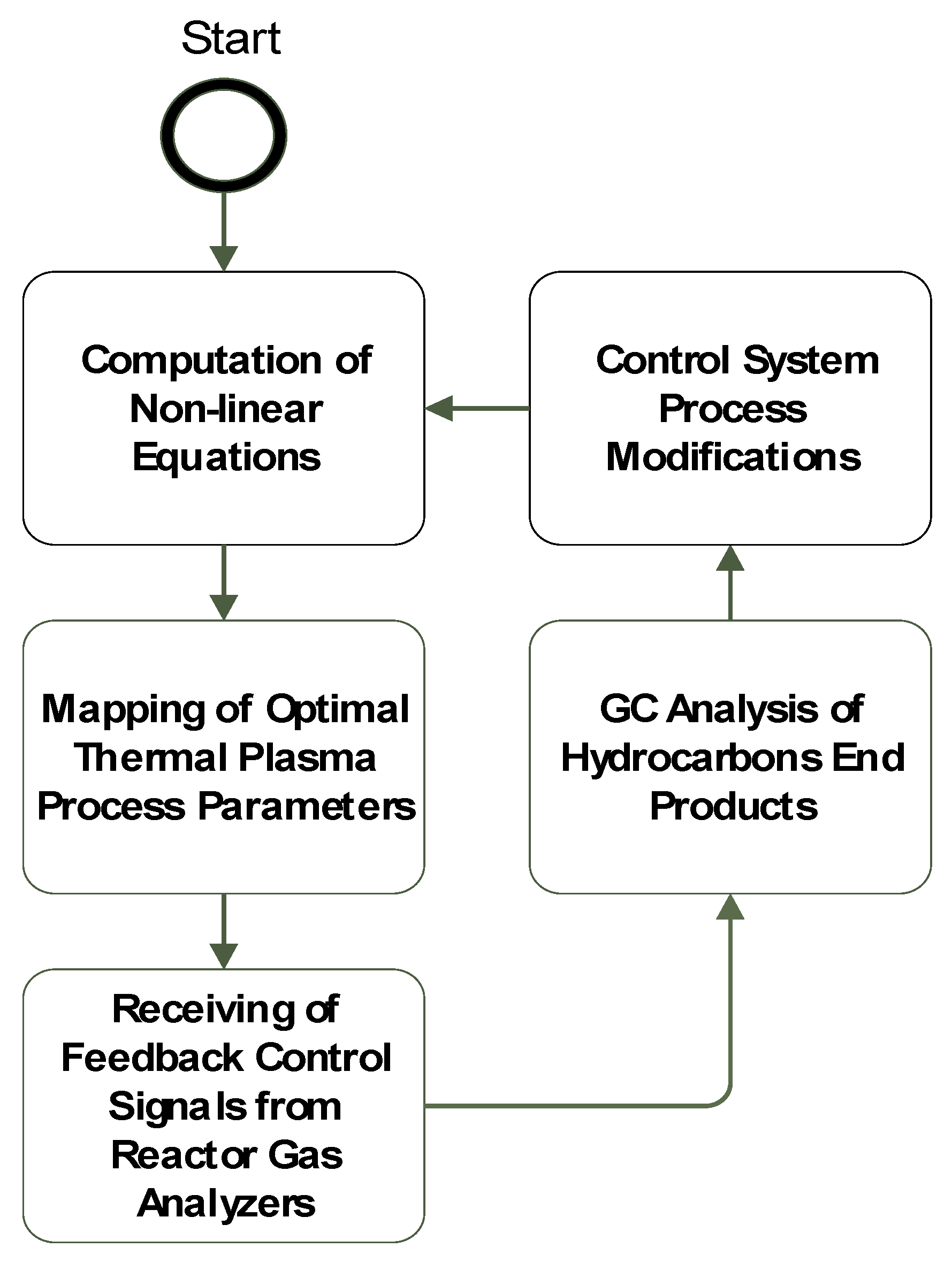
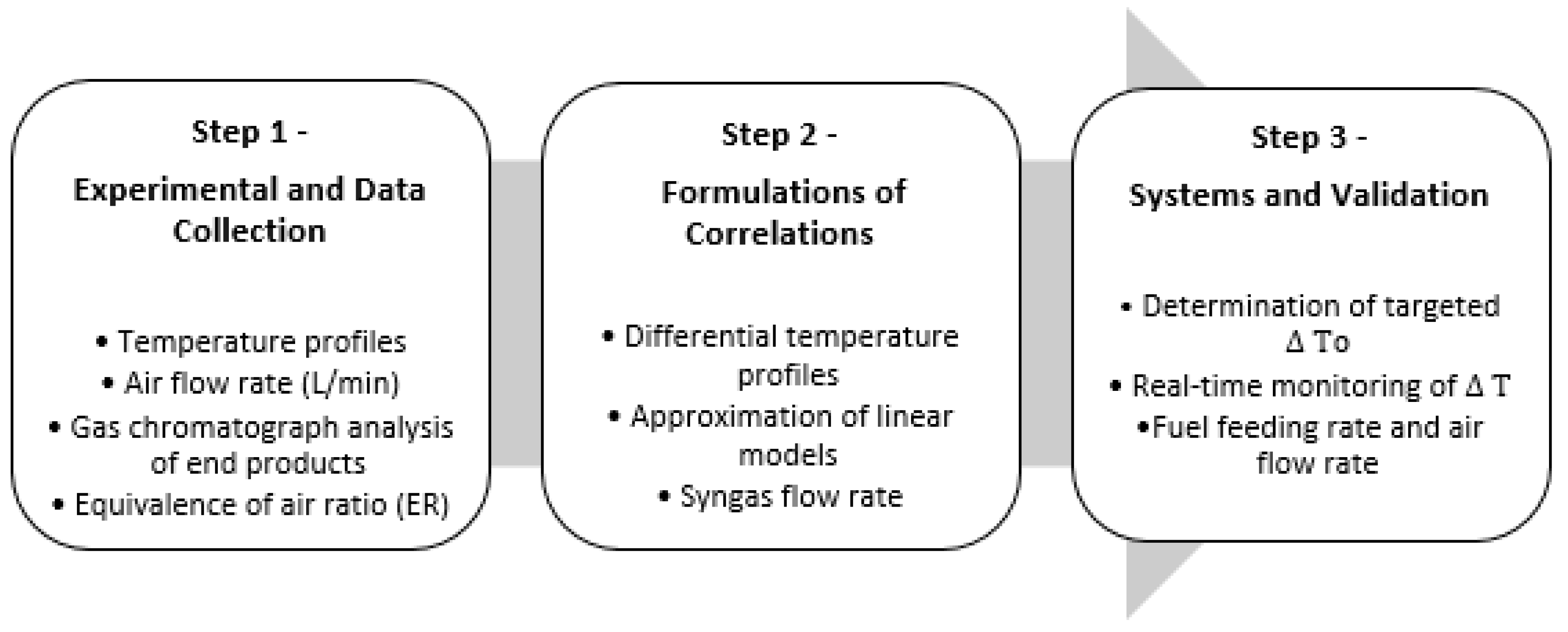
2.4. Process Control Modelling

End-Product Gas Yield Control Algorithms

The gaseous products produced during the gasification process indicate the reaction conversion efficiency. η Gas is the ratio between the volumetric flow rate of outlet gases from the gasifier to the initial mass flow rate of the solid waste presented by the equation below [21]:
η Gas = Q Syngas M MSW
where Qsyngas and M MSW are the volumetric flow rate and mass flow rate of syngas and solid waste, respectively [22].

3. RF Thermal Plasma Simulation

The following RF-ICP simulation model demonstrates the thermal performance of the ICP thermal plasma torch in thermochemical reactions. The following assumptions are assumed in the simulation [3]:
  • Thermal plasma is under a local partial thermodynamic equilibrium (LTE);
  • Plasma is considered a conductive fluid mixture and is modelled using magnetohydrodynamics (MHD) equations;
  • The thermal plasma jet is axisymmetric, optically thin, and at a local thermodynamic equilibrium;
  • The gaseous velocity is constant at laminar flow with no tangential components;
  • The displacement current and electrostatic fields are neglected.

3.1. RF Torch Assumptions

  • The RF thermal plasma torch model has an axisymmetric configuration;
  • The torch consists of eight turns with a cross-sectional coil diameter of 3 mm;
  • Flow is assumed to be steady state, laminar flow of pure argon flow at 7.5 L/min;
  • The thermal plasma jet is thin and at local thermodynamic equilibrium (LTE) conditions;
  • Viscous dissipation and change in pressure are neglected in energy conservation equations.

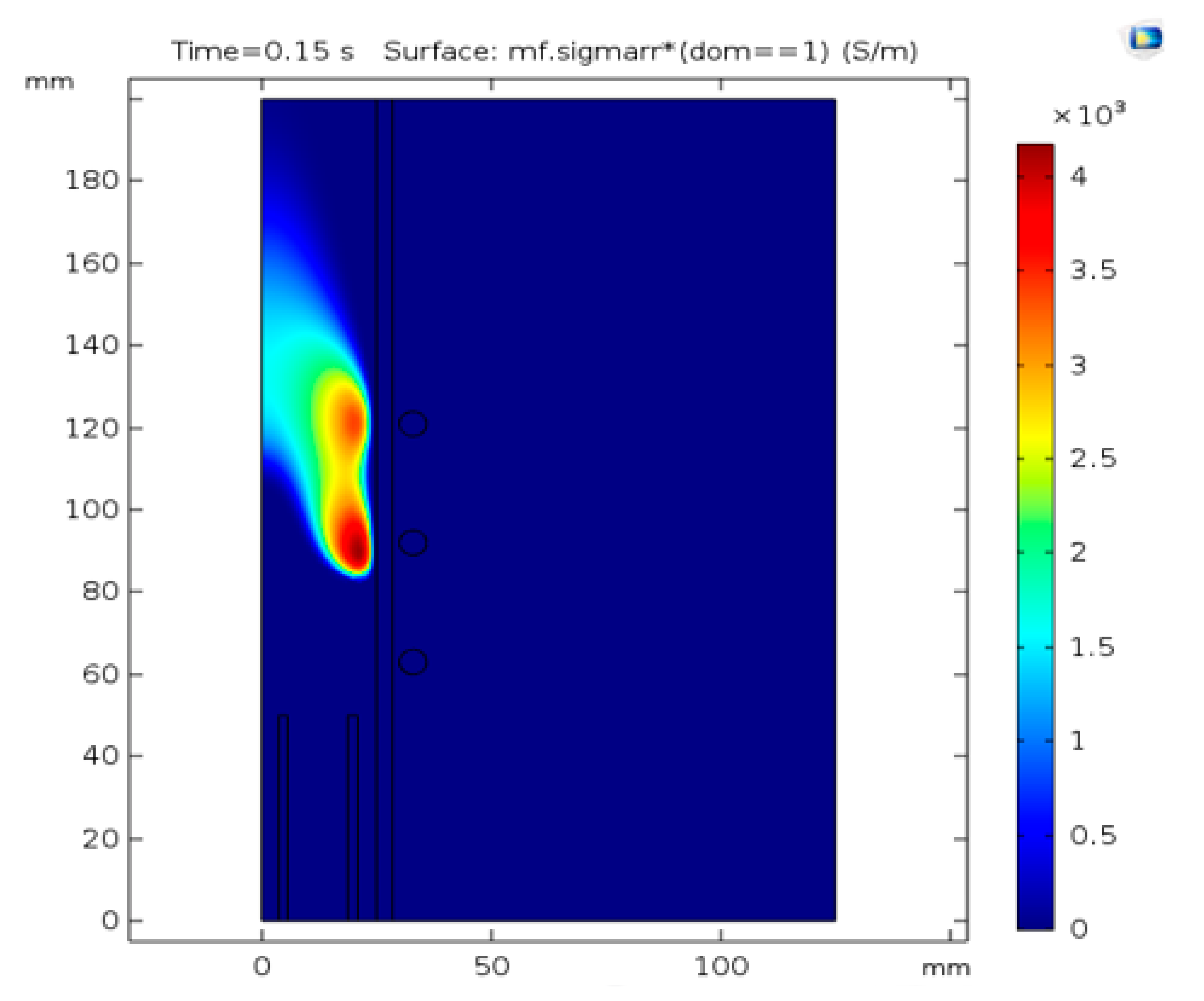
3.2. RF Thermal Plasma Comsol Simulation

The Comsol model geometry for a 1000 W RF plasma torch at 13.56 MHz and argon gas flow at 7.5 L/min in the sheath tube is shown below in Figure 6, Figure 7, Figure 8 and Figure 9.

4. Experimental Apparatus

4.1. Equipment Description and Experimental Procedures

Shredded plastic waste is added to the closed system reactor via a side ball valve followed by continuous nitrogen gas flow and purging inside the reaction chamber. The gas analyzers give real-time gaseous measurement of the weight content (wt.%) inside the reactor for oxygen (O2), carbon monoxide (CO), nitrogen oxides (NOx) and carbon monoxide (CO2). The gas analyzers ensure that there is negligible oxygen content inside the reaction chamber during startup and operation. The RF thermal plasma torch is used as a primary heat source for thermochemical reactions, and the k-type thermocouple provides real-time measurement. The RF torch is used as a primary heat and thermal control source. The torch current is increased until the desired operating temperature is reached (i.e., 550 °C for Pyrolysis and 900 °C for gasification). The RF thermal plasma torch temperature is maintained during the reaction residence time until desired hydrocarbon products are produced. (For pyrolysis τ = 30 min, gasification τ = 1 sec). For pyrolysis, after completion of the reaction residence time, the thermal plasma torch is switched off and the hydrocarbon gaseous products pass through a condensation system where hydrocarbon products are condensed at room temperature and collected. The condensation system is used to condense hydrocarbon gaseous products leaving the reactor. For gasification, a continuous flow of syngas passes through a syngas turbine and then combusted for steam and electricity generation purposes. Gas samples are collected during and after experimental trials and identified using the gas chromatograph-flame ionization detector method. The GC-FID (gas chromatograph-flame ionization detector method) is used to provide molecular weight readings and identify the molecular weights of hydrocarbon gaseous and liquid end-products.

4.2. Equipment Setup

The RF thermal plasma reaction experimental apparatus consists of the following equipment, as shown in Figure 10:
  • An RF thermal plasma cathode cooling water to prevent resistive heat;
  • A constant argon gas supply at 7.5 L/min;
  • Three gas analyzers: CO, CO2 and NOx;
  • A startup graphite electrode (diameter: 10 mm);
  • A 1000 W RF thermal plasma system;
  • Diagnostic equipment including a gas chromatograph;
  • A high-pressure steam boiler and steam turbine for energy generation.

Reaction Apparatus Legend

(1).
Comsol Simulation Software
(2).
Nitrogen and Argon Gas Cylinders
(3).
Pyrolysis Reactor
(4).
Gasification Reactor
(5).
Steam Boiler
(6).
Steam Turbine
(7).
DAQ (Data Acquisition System)
(8).
Gas Chromatography
(9).
Steam Turbine

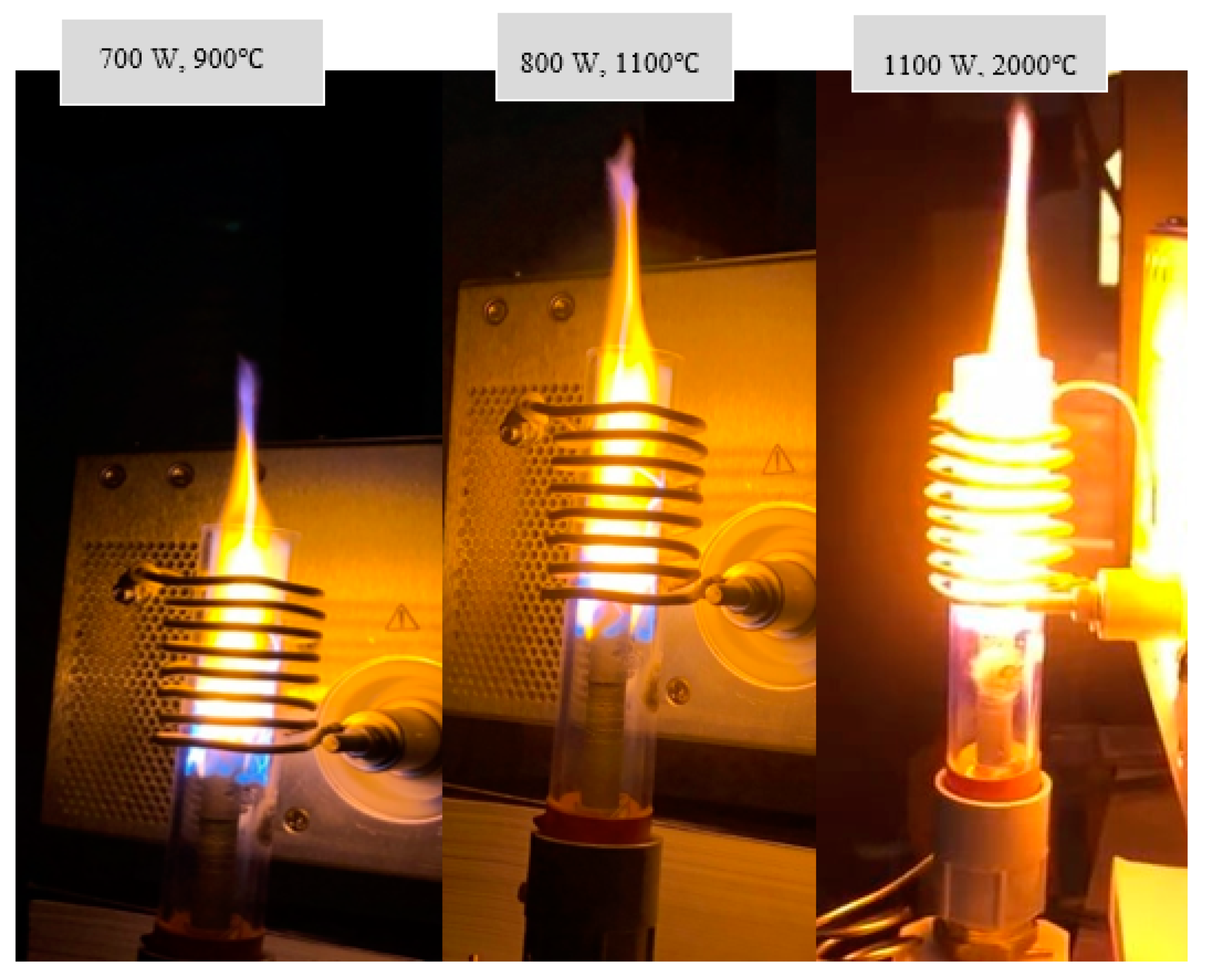
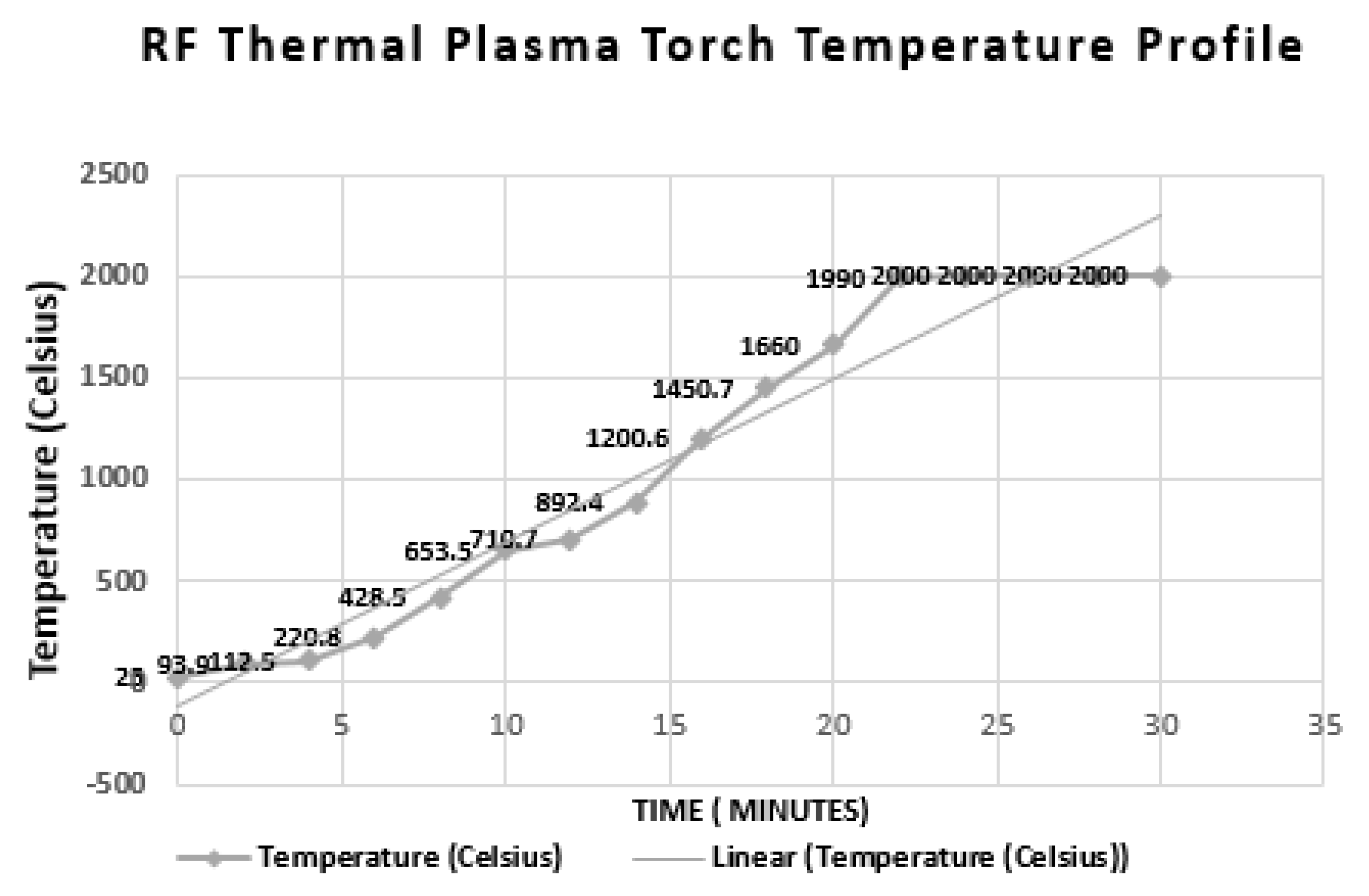
4.3. RF Thermal Plasma Torch Dimensions and Temperature Profile

The RF Plasma torch was successfully switched on and reached a maximum operating temperature of 2000 °C. The RF torch fused quartz tube dimensions are 14 cm length, 2.5 cm outer diameter and 2.5 mm thickness. For its RF torch, a 4.7 cm length, 8 turn copper coil made by a 3 mm diameter copper tube was used. RF coil inductance was calculated to be 1.5 uH. During experimental work, the RF plasma torch was ignited using a graphite rod at constant argon gas flow at 7.5 l/min and Δ   35 °C/min. The temperature recordings are shown in Figure 11 and Figure 12.

4.4. Experimental Analysis and Results

Figure 13 shows the RF plasma torch in operation at an average heating rate of Δ   35 °C/min. Resistive heat is prevented using cooling water flow inside the hollow copper tube. The oil collected from 1 kg of thermoplastic waste mixture showed a conversion efficiency yield of 89 wt.%. The collected oil was identified using GC-FID (gas chromatograph-flame ionization detector method) showing 90 wt.% n-butyl-benzene (C6H5C4H9) and toluene (C7H8) with less than 10 wt.% decane diesel fuel (C10 H22). Figure 13 shows identified n-butyl-benzene (C6H5C4H9) and toluene (C7H8) as well as decane (C10H22).

5. Conclusions

In conclusion, the experiment showed that an RF thermal plasma nearly eliminates the tar content which was reflected in the gas chromatograph results (i.e., C 34) as shown in Figure 13. Also, RF thermal plasma showed enhancement of the chemical reactivity of thermoplastic pyrolysis reactions. In the demonstrated experimental work, the achieved conversion efficiency was 89 wt.% for the pyrolysis process at the operating temperature (550–900 °C and above 90 wt.% for the gasification process. The RF thermal plasma torch average heating rate was +35 °C/min and reached a maximum operating temperature of 2000 °C, maintaining sustainable thermal plasma for more than 30 minutes. The collected hydrocarbon end-products were 90 wt.% n-butyl-benzene (C6H5C4H9) and toluene (C7H8) with less than 10 wt.% decane diesel fuel (C10 H22). Negligible tar and char were collected as residue.

Author Contributions

H.A.G., V.D. and M.A. carried the conceptual design and designed the experimental apparatus. V.D., M.A. and I.H. carried the experimental trials and analyzed data, M.A. wrote the paper. All authors have read and agreed to the published version of the manuscript.

Funding

This research was funded by Proflange Ltd., a leading Canadian stainless manufacturing company for industrial applications.

Acknowledgments

The thermal plasma team would like to acknowledge Proflange Ltd. for their funding and continuous support.

Conflicts of Interest

The authors declare no conflict of interest.

Abbreviations & Nomenclature

Abbreviations
CCPCapacitively Coupled Plasma
DCDirect Current
FIDFlame Ionization Detector Gas Chromatograph
F-TFischer-Tropsch process
GGasification
GC-FIDGas Chromatograph-Flame Ionization Detector method
GHGGreenhouse Gas Emissions
IIncineration
ICPInductively Coupled Plasma
LDPELow Density Polyethylene
MSWMunicipal Solid Waste
OECDOrganization for Economic Co-operation and Development
PPyrolysis
P-GCombined Pyrolysis and Gasification Process
RFRadio Frequency
Nomenclature
FrForce in the radial direction
FzForce in the axial direction
F ( u ) Number of particles per m3
JrPlasma flux density in radial direction, (kg/m3)
KKelvin
KWhkilowatt-hour
ρ Density (kg/m3)
T e Electron temperature, K
TiInitial operating temperature, K
T 0 Atmospheric temperature, K
t Change in time, seconds
τ Reaction residence time (minutes)
v Velocity, (m/s)
vrVelocity in the radial direction, (m/s)
vzVelocity in the axial direction, (m/s)
wt.%Weight percentage
ω 2 Angular velocity, (m/s)
z Change in axial direction, m

References

  1. Kawai, K.; Tasaki, T. Revisiting estimates of municipal solid waste generation per capita and their reliability. J. Mater. Cycles Waste Manag. 2016, 18, 1–13. [Google Scholar] [CrossRef] [Green Version]
  2. Karak, T.; Bhagat, R.M.; Bhattacharyya, P. Municipal solid waste generation, composition, and management: The world scenario. Crit. Rev. Env. Sci. Technol. 2012, 42, 1509–1630. [Google Scholar] [CrossRef]
  3. Alhumid, H.A.; Haider, H.; Alsaleem, S.S.; Alinizzi, M.; Shafiquzaman, M.; Sadiq, R. Performance assessment model for municipal solid waste management systems: Development and implementation. Environments 2019, 6, 19. [Google Scholar] [CrossRef] [Green Version]
  4. David, A. Technical Document on Municipal Solid Waste Organics Processing. Available online: https://www.ec.gc.ca/gdd-mw/3E8CF6C7-F214-4BA2-A1A3-163978EE9D6E/13-047-ID-458-PDF_accessible_ANG_R2-reduced%20size.pdf (accessed on 30 January 2020).
  5. Niessen, W.R. Combustion and Incineration Processes. J. Chem. Inf. Model. 2010, 52, 11. [Google Scholar]
  6. Mohareb, A.K.; Warith, M.A.; Diaz, R. Modelling greenhouse gas emissions for municipal solid waste management strategies in Ottawa, Ontario, Canada. Resour. Conserv. Recycl. 2008, 52, 1241–1251. [Google Scholar] [CrossRef]
  7. Global Waste Management Outlook. 2016. Available online: https://www.unenvironment.org/resources/report/global-waste-management-outlook (accessed on 30 January 2020).
  8. Fabry, F.; Rehmet, C.; Rohani, V.; Fulcheri, L. Waste gasification by thermal plasma: A review. Waste Biomass Valorization 2013, 4, 421–439. [Google Scholar] [CrossRef] [Green Version]
  9. Arena, U.; Nelles, M.; Werther, J. Advanced aspects of thermal treatment of solid wastes: From a flue gas to a fuel gas technology? Waste Manag. 2012, 32, 623–624. [Google Scholar] [CrossRef] [PubMed]
  10. Albores, P.; Petridis, K.; Dey, P.K. Analysing Efficiency of Waste to Energy Systems: Using Data Envelopment Analysis in Municipal Solid Waste Management. Procedia Environ. Sci. 2016, 35, 265–278. [Google Scholar] [CrossRef]
  11. Rajasekhar, M.; Rao, N.V.; Rao, G.C.; Priyadarshini, G.; Kumar, N.J. Energy Generation from Municipal Solid Waste by Innovative Technologies – Plasma Gasification. Procedia Mater. Sci. 2015, 10, 513–518. [Google Scholar] [CrossRef] [Green Version]
  12. Ruj, B.; Ghosh, S. Technological aspects for thermal plasma treatment of municipal solid waste-A review. Fuel Process. Technol. 2014, 126, 298–308. [Google Scholar] [CrossRef]
  13. Gomez, E.; Rani, D.A.; Cheeseman, C.R.; Deegan, D.; Wise, M.; Boccaccini, A.R. Thermal plasma technology for the treatment of wastes: A critical review. J. Hazard. Mater. 2009, 161, 614–626. [Google Scholar] [CrossRef]
  14. Samal, S. Thermal plasma technology: The prospective future in material processing. J. Cleaner Prod. 2017, 142, 3131–3150. [Google Scholar] [CrossRef]
  15. Trelles, J.P.; Chazelas, C.; Vardelle, A.; Heberlein, J.V.R. Arc Plasma Torch Modeling. J. Therm. Spray Technol. 2009, 18, 728. [Google Scholar] [CrossRef] [Green Version]
  16. Bai, L.; He, J.; Ouyang, Y.; Liu, W.; Liu, H.; Yao, H.; Li, Z.; Song, J.; Wang, Y.; Yuan, F. Modeling and selection of RF thermal plasma hot-wall torch for large-scale production of nanopowders. Materials 2019, 12, 2141. [Google Scholar] [CrossRef] [PubMed] [Green Version]
  17. Rao, L.; Rivard, F.; Carabin, P. Thermal plasma torches for metallurgical applications. In Proceedings of the 4th International Symposium on High-Temperature Metallurgical Processing, San Antonio, TX, USA, 3–7 March 2013. [Google Scholar]
  18. Ochoa Brezmes, A.; Breitkopf, C. Simulation of inductively coupled plasma with applied bias voltage using COMSOL. Vacuum 2014, 109, 52–60. [Google Scholar] [CrossRef]
  19. Kim, T.H.; Kim, K.N.; Mishra, A.K.; Seo, J.S.; Jeong, H.B.; Bae, J.O.; Yeom, G.Y. Plasma characteristics of inductively coupled plasma using dual-frequency antennas. Jpn. J. Appl. Phys. 2013, 52, 5S2. [Google Scholar] [CrossRef]
  20. Bernardi, D.; Colombo, V.; Coppa, G.G.M.; D’Angola, A. Simulation of the ignition transient in RF inductively-coupled plasma torches. Eur. Phys. J. D. 2001, 14, 337–348. [Google Scholar] [CrossRef]
  21. Taghavipour, A.; Vajedi, M.; Azad, N.L. Nonlinear Model Predictive Control. In Intelligent Control of Connected Plug-in Hybrid Electric Vehicles; Advances in Industrial Control; Springer: Cham, Switzerland, 2019; pp. 45–47. [Google Scholar]
  22. Wickramasinghe, D.G.C.; Narayana, M.; Witharana, S. Optimization of Process Parameters for Organic Municipal Solid Waste Torrefaction. In Proceedings of the 2019 Advances in Science and Engineering Technology International Conferences (ASET), Dubai, UAE, 26 March–10 April 2019. [Google Scholar]
Figure 1. Current municipal solid waste recycling practices in the Organization for Economic Co-operation and Development (OECD) countries [1].
Processes 08 00281 g001
Figure 2. Net energy production to grid from different thermochemical processes (KWh/ton of MSW).
Processes 08 00281 g002
Figure 3. Categories of thermal plasma temperature characteristics.
Processes 08 00281 g003
Figure 4. Integration of RF thermal plasma torch in pyrolysis reaction chamber flowchart.
Processes 08 00281 g004
Figure 5. Process flow diagram for real-time monitoring control for thermochemical reactors.
Processes 08 00281 g005
Figure 6. RF thermal plasma torch temperature profile.
Processes 08 00281 g006
Figure 7. Meshing of the RF thermal plasma torch.
Processes 08 00281 g007
Figure 8. RF thermal plasma torch conductivity (S/m).
Processes 08 00281 g008
Figure 9. Surface magnetic flux density (S/m).
Processes 08 00281 g009
Figure 10. RF thermal plasma thermochemical reaction apparatus.
Processes 08 00281 g010
Figure 11. Self-ignited RF thermal plasma torch at 7.5 L/min flow exceeding 2000 °C.
Processes 08 00281 g011
Figure 12. RF thermal plasma torch temperature reading.
Processes 08 00281 g012
Figure 13. RF thermal plasma pyrolysis GC analysis results.
Processes 08 00281 g013
Table 1. Operating temperatures and applications of thermal plasma jets.
Process VariableNon-Thermal PlasmaLow Temperature Thermal PlasmaHigh Temperature Thermal Plasma
Operating TemperatureTi Te < 300 KTi Te < 103 KTi Te > 106 K
ApplicationsThermal arc emissions, low pressure glow discharges Waste-to-energy, metallurgical applicationsFusion experimental work
Table 2. Maximum allowable tar rates in industrial gasification systems (g/nm3).
Reactor ConfigurationTar Rates (g/Nm3)
Process Units
Tar Rates (g/Nm3)
Internal Combustion Engines and Turbines
MinMaxAverageMinMaxAverage
Updraft115020–1000.130.1–1
Downdraft0.0560.1–1.50.01100.1–0.2

