Isolated Taylor Bubbles in Co-Current with Shear Thinning CMC Solutions in Microchannels—A Numerical Study


Abstract
1. Introduction
2. Materials and Methods
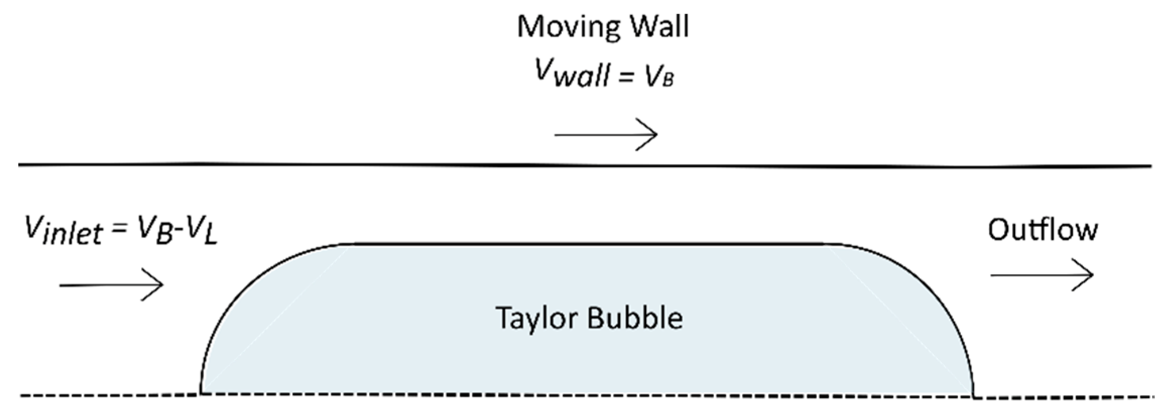
2.1. Domain and Numerical Method
2.2. Governing Equations
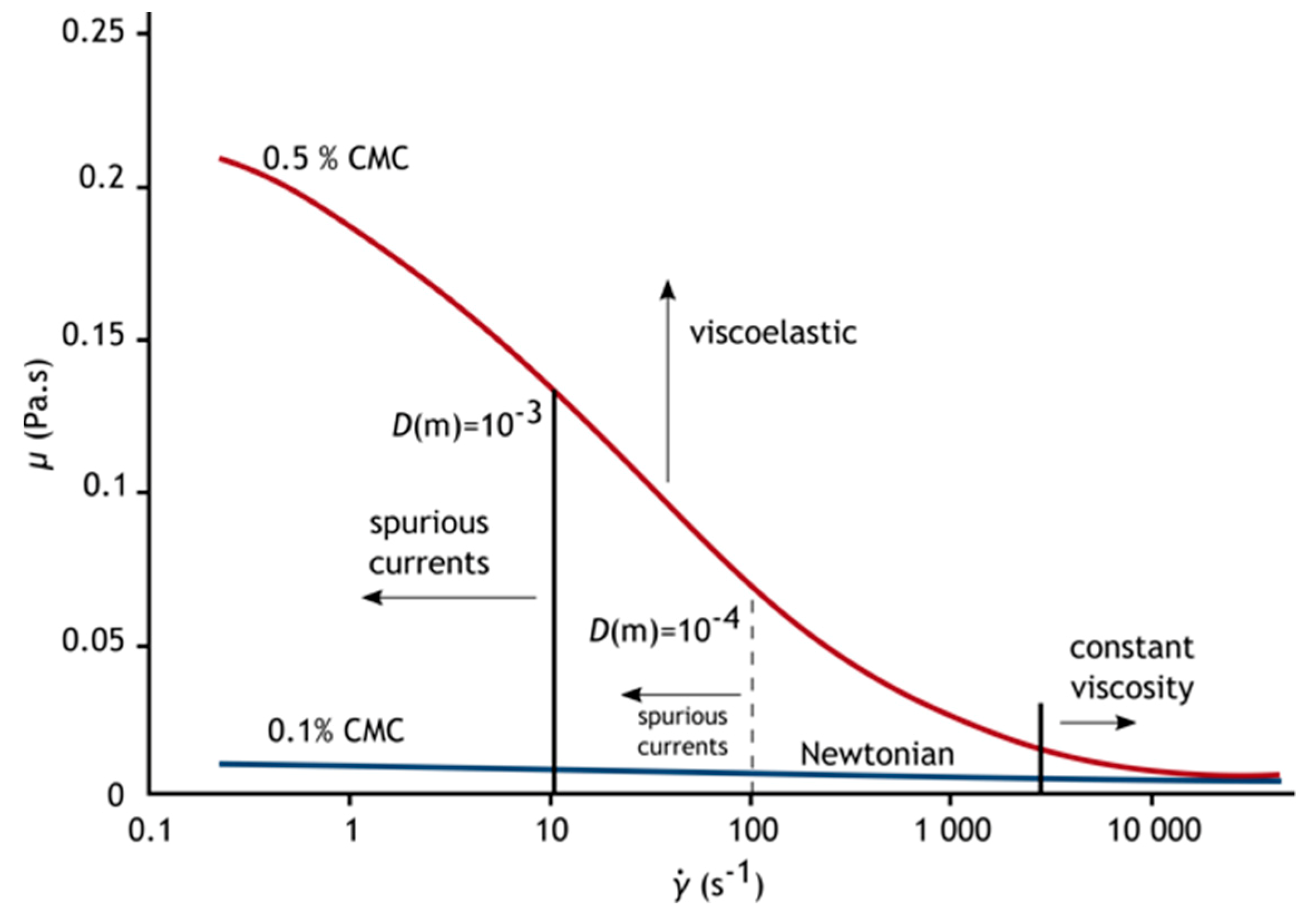
2.3. Fluids
2.4. Non-Dimensional Parameters
3. Results
3.1. Study Design
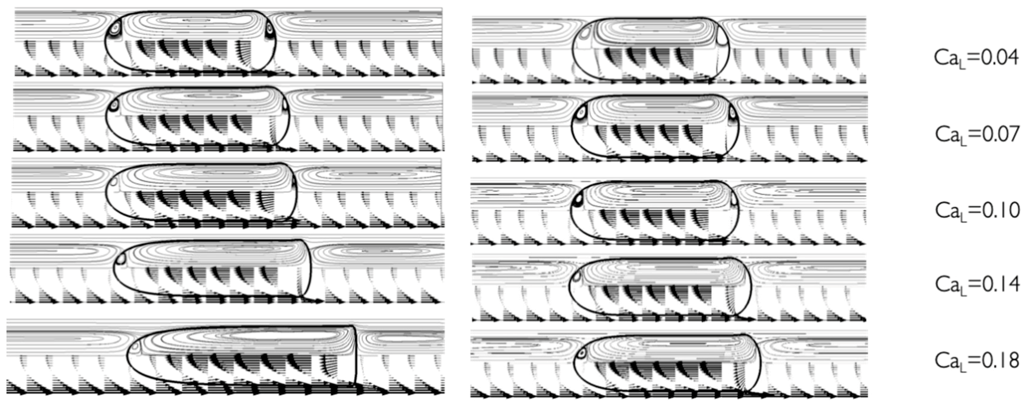
3.2. Flow Fields
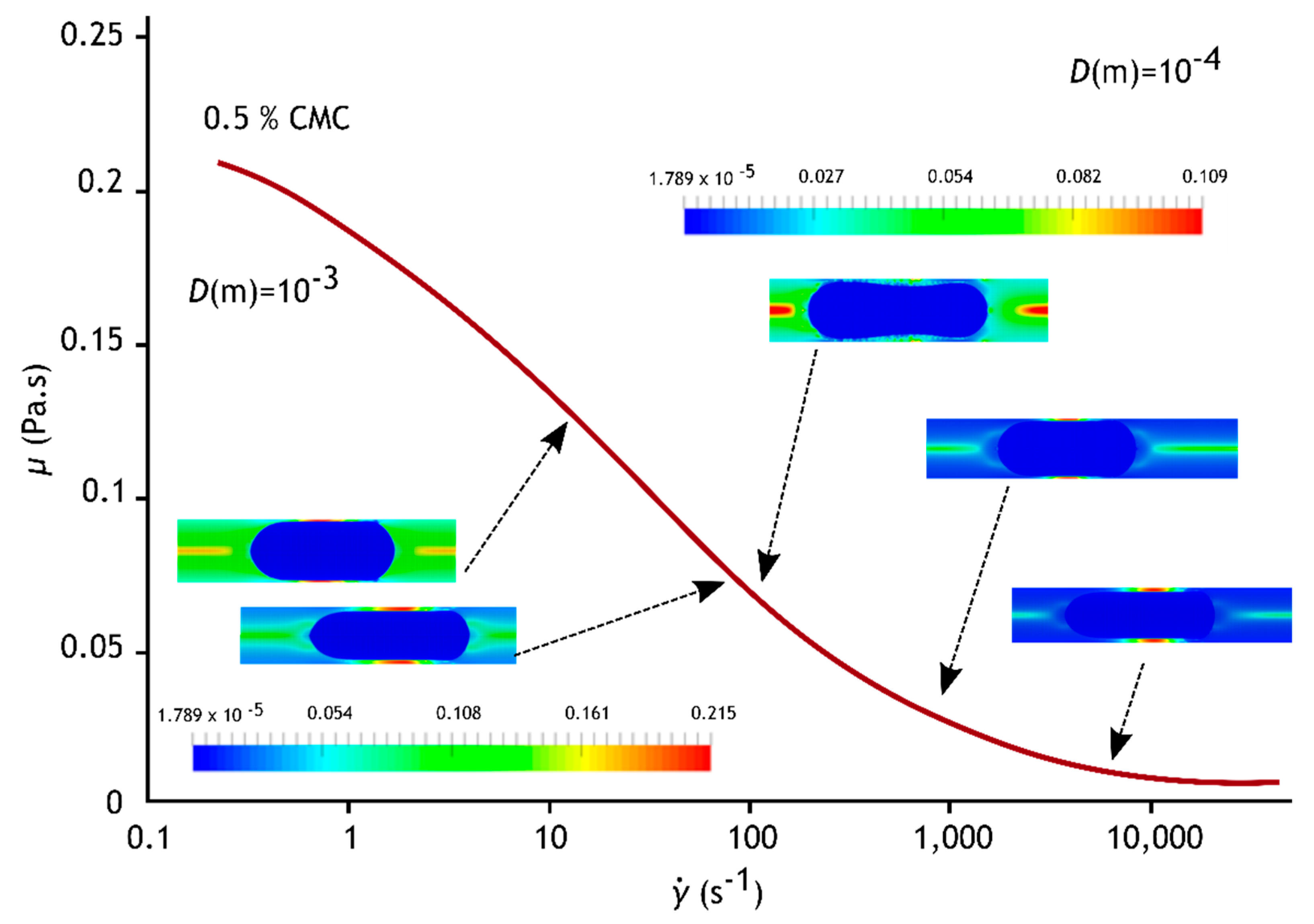
3.3. Viscosity Fields
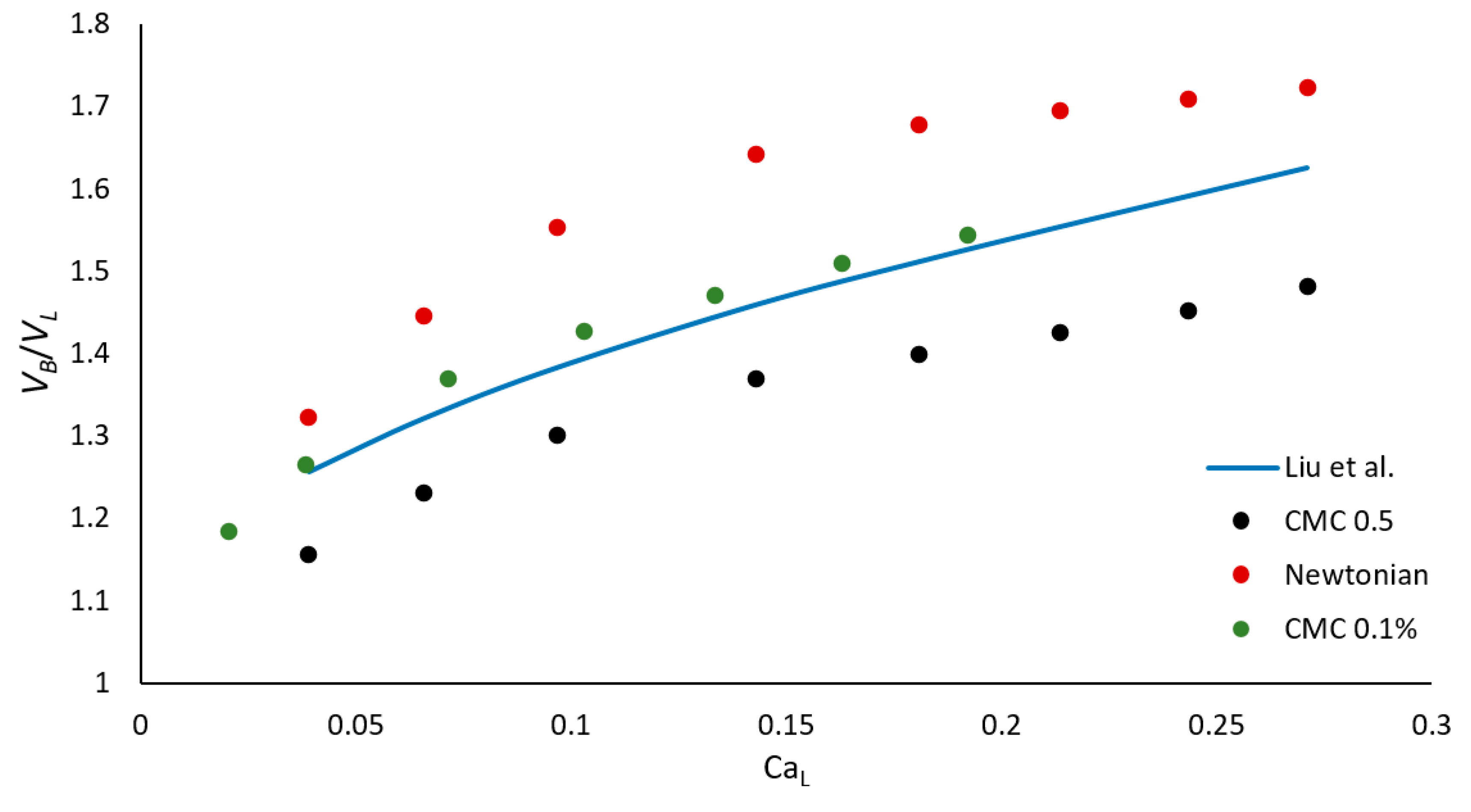
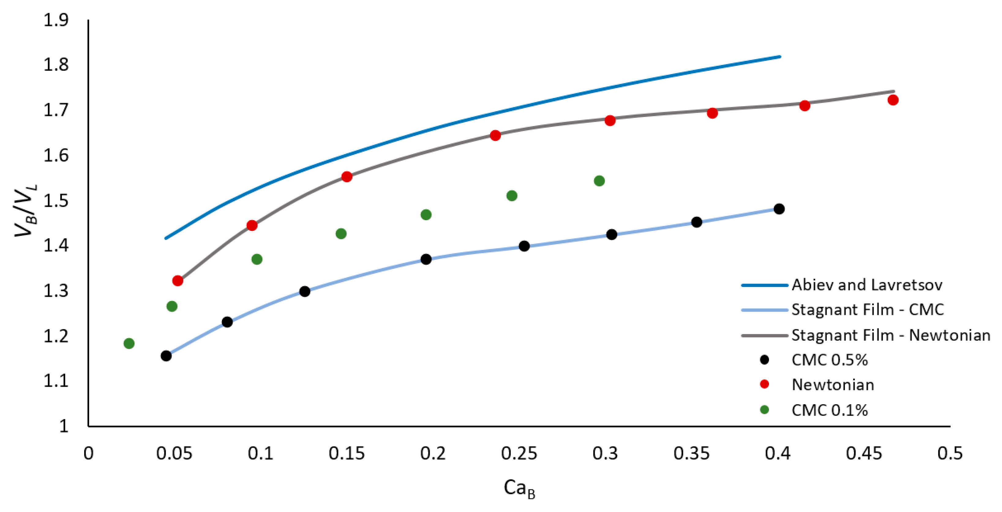
3.4. Bubble Velocity
3.5. Film Thickness
4. Conclusions
Author Contributions
Funding
Conflicts of Interest
References
- Thulasidas, T.C.; Abraham, M.A.; Cerro, R.L. Flow patterns in liquid slugs during bubble-train flow inside capillaries. Chem. Eng. Sci. 1997, 52, 2947–2962. [Google Scholar] [CrossRef]
- Thulasidas, T.C.; Abraham, M.A.; Cerro, R.L. Dispersion during bubble-train flow in capillaries. Chem. Eng. Sci. 1999, 54, 61–76. [Google Scholar] [CrossRef]
- Taha, T.; Cui, Z.F. Hydrodynamics of slug flow inside capillaries. Chem. Eng. Sci. 2004, 59, 1181–1190. [Google Scholar] [CrossRef]
- Sousa, R.G.; Riethmuller, M.L.; Pinto, A.M.F.R.; Campos, J.B.L.M. Flow around individual Taylor bubbles rising in stagnant CMC solutions: PIV measurements. Chem. Eng. Sci. 2005, 60, 1859–1873. [Google Scholar] [CrossRef]
- Morgado, A.O.; Miranda, J.M.; Araújo, J.D.P.; Campos, J.B.L.M. Review on vertical gas–liquid slug flow. Int. J. Multiph. Flow 2016, 85, 348–368. [Google Scholar] [CrossRef]
- Nigmatulin, T.R.; Bonetto, F.J. Shape of Taylor bubbles in vertical tubes. Int. Commun. Heat Mass Transf. 1997, 24, 1177–1185. [Google Scholar] [CrossRef]
- Han, Y.; Shikazono, N. The effect of bubble acceleration on the liquid film thickness in micro tubes. Int. J. Heat Fluid Flow 2010, 31, 630–639. [Google Scholar] [CrossRef]
- Triplett, K.A.; Ghiaasiaan, S.M.; Abdel-Khalik, S.I.; Sadowski, D.L. Gas–liquid two-phase flow in microchannels Part I: Two-phase flow patterns. Int. J. Multiph. Flow 1999, 25, 377–394. [Google Scholar] [CrossRef]
- Thulasidas, T.C.; Abraham, M.A.; Cerro, R.L. Bubble-train flow in capillaries of circular and square cross section. Chem. Eng. Sci. 1995, 50, 183–199. [Google Scholar] [CrossRef]
- Han, Y.; Shikazono, N. Measurement of the liquid film thickness in micro tube slug flow. Int. J. Heat Fluid Flow 2009, 30, 842–853. [Google Scholar] [CrossRef]
- Bugg, J.D.; Mack, K.; Rezkallah, K.S. A numerical model of Taylor bubbles rising through stagnant liquids in vertical tubes. Int. J. Multiph. Flow 1998, 24, 271–281. [Google Scholar] [CrossRef]
- Malekzadeh, R.; Henkes, R.; Mudde, R. Severe slugging in a long pipeline–riser system: Experiments and predictions. Int. J. Multiph. Flow 2012, 46, 9–21. [Google Scholar] [CrossRef]
- Nešić, S. Key issues related to modelling of internal corrosion of oil and gas pipelines—A review. Corros. Sci. 2007, 49, 4308–4338. [Google Scholar] [CrossRef]
- Bento, D.; Sousa, L.; Yaginuma, T.; Garcia, V.; Lima, R.; Miranda, J.M. Microbubble moving in blood flow in microchannels: Effect on the cell-free layer and cell local concentration. Biomed. Microdevices 2017, 19, 6. [Google Scholar] [CrossRef] [PubMed]
- Silva, M.C.; Araújo, J.D.; Campos, J.B. CFD studies coupling hydrodynamics and solid-liquid mass transfer in slug flow for matter removal from tube walls. AIChE J. 2017, 63, 2420–2439. [Google Scholar] [CrossRef]
- Silva, M.; Campos, J.; Araújo, J. Mass transfer from a soluble wall into gas-liquid slug flow in a capillary tube. Int. J. Heat Mass Transf. 2019, 132, 745–761. [Google Scholar] [CrossRef]
- Stride, E.; Saffari, N. Microbubble ultrasound contrast agents: A review. Proc. Inst. Mech. Eng. H 2003, 217, 429–447. [Google Scholar] [CrossRef]
- Laporte, M.; Montillet, A.; Belkadi, A.; Della Valle, D.; Loisel, C.; Riaublanc, A.; Hauser, J. Investigation of gas/shear-thinning liquids flow at high throughput in microchannels with the aim of producing biosourced foam. Chem. Eng. Process. Process Intensif. 2019, 148, 107787. [Google Scholar] [CrossRef]
- Bento, D.; Lopes, S.; Maia, I.; Pereira, A.; Fernandes, C.; Miranda, J.; Lima, R. Blood Flow of Bubbles Moving in Microchannels with Bifurcations. In Proceedings of the ECCOMAS Thematic Conference on Computational Vision and Medical Image Processing, Porto, Portugal, 16–18 October 2019; pp. 571–577. [Google Scholar]
- Araújo, J.; Miranda, J.; Campos, J. Taylor bubbles rising through flowing non-Newtonian inelastic fluids. J. Non-Newton. Fluid Mech. 2017, 245, 49–66. [Google Scholar] [CrossRef]
- Suo, M.; Griffith, P. Two-Phase Flow in Capillary Tubes. J. Basic Eng. 1964, 86, 576–582. [Google Scholar] [CrossRef]
- Bretherton, F.P. The motion of long bubbles in tubes. J. Fluid Mech. 1961, 10, 166–188. [Google Scholar] [CrossRef]
- Sousa, R.G.; Pinto, A.M.F.R.; Campos, J.B.L.M. Interaction between Taylor bubbles rising in stagnant non-Newtonian fluids. Int. J. Multiph. Flow 2007, 33, 970–986. [Google Scholar] [CrossRef]
- Majumdar, A.; Das, P. Rise of Taylor bubbles through power law fluids–Analytical modelling and numerical simulation. Chem. Eng. Sci. 2019, 205, 83–93. [Google Scholar] [CrossRef]
- Zhang, T.; Cao, B.; Fan, Y.; Gonthier, Y.; Luo, L.; Wang, S. Gas–liquid flow in circular microchannel. Part I: Influence of liquid physical properties and channel diameter on flow patterns. Chem. Eng. Sci. 2011, 66, 5791–5803. [Google Scholar] [CrossRef]
- Yang, Z.C.; Bi, Q.C.; Liu, B.; Huang, K.X. Nitrogen/non-Newtonian fluid two-phase upward flow in non-circular microchannels. Int. J. Multiph. Flow 2010, 36, 60–70. [Google Scholar] [CrossRef]
- Mansour, M.H.; Kawahara, A.; Sadatomi, M. Experimental investigation of gas–non-Newtonian liquid two-phase flows from T-junction mixer in rectangular microchannel. Int. J. Multiph. Flow 2015, 72, 263–274. [Google Scholar] [CrossRef]
- Fu, T.; Ma, Y.; Funfschilling, D.; Li, H.Z. Gas–liquid flow stability and bubble formation in non-Newtonian fluids in microfluidic flow-focusing devices. Microfluid. Nanofluidics 2011, 10, 1135–1140. [Google Scholar] [CrossRef]
- Abadie, T.; Aubin, J.; Legendre, D.; Xuereb, C. Hydrodynamics of gas–liquid Taylor flow in rectangular microchannels. Microfluid. Nanofluidics 2012, 12, 355–369. [Google Scholar] [CrossRef]
- Chaoqun, Y.; Yuchao, Z.; Chunbo, Y.; Minhui, D.; Zhengya, D.; Guangwen, C. Characteristics of slug flow with inertial effects in a rectangular microchannel. Chem. Eng. Sci. 2013, 95, 246–256. [Google Scholar] [CrossRef]
- Fairbrother, F.; Stubbs, A.E. 119. Studies in electro-endosmosis. Part VI. The “bubble-tube” method of measurement. J. Chem. Soc. 1935, 527–529. [Google Scholar] [CrossRef]
- Taylor, G.I. Deposition of a viscous fluid on the wall of a tube. J. Fluid Mech. 2006, 10, 161–165. [Google Scholar] [CrossRef]
- Chen, J.-D. Measuring the film thickness surrounding a bubble inside a capillary. J. Colloid Interface Sci. 1986, 109, 341–349. [Google Scholar] [CrossRef]
- Irandoust, S.; Andersson, B. Liquid film in Taylor flow through a capillary. Ind. Eng. Chem. Res. 1989, 28, 1684–1688. [Google Scholar] [CrossRef]
- Aussillous, P.; Quéré, D. Quick Deposition of a Fluid on the Wall of a Tube. Am. Inst. Phys. 2000, 12, 2367–2371. [Google Scholar] [CrossRef]
- Han, Y.; Shikazono, N. Thickness of liquid film formed in slug flow in micro tube. In Proceedings of the ECI International Conference on Heat Transfer and Fluid Flow in Microscale, Whistler, BC, Canada, 21–26 September 2008; pp. 21–26. [Google Scholar]
- Liu, H.; Vandu, C.O.; Krishna, R. Hydrodynamics of Taylor Flow in Vertical Capillaries: Flow Regimes, Bubble Rise Velocity, Liquid Slug Length, and Pressure Drop. Ind. Eng. Chem. Res. 2005, 44, 4884–4897. [Google Scholar] [CrossRef]
- Abiev, R.S.; Lavretsov, I. Intensification of mass transfer from liquid to capillary wall by Taylor vortices in minichannels, bubble velocity and pressure drop. Chem. Eng. Sci. 2012, 74, 59–68. [Google Scholar] [CrossRef]
- Rocha, L.; Miranda, J.; Campos, J. Wide range simulation study of taylor bubbles in circular milli and microchannels. Micromachines 2017, 8, 154. [Google Scholar] [CrossRef]
- Hirt, C.W.; Nichols, B.D. Volume of fluid (VOF) method for the dynamics of free boundaries. J. Comput. Phys. 1981, 39, 201–225. [Google Scholar] [CrossRef]
- Youngs, D.L. Time-dependent multi-material flow with large fluid distortion. Numer. Methods Fluid Dyn. 1982, 273–285. [Google Scholar]
- Brackbill, J.U.; Kothe, D.B.; Zemach, C. A continuum method for modeling surface tension. J. Comput. Phys. 1992, 100, 335–354. [Google Scholar] [CrossRef]


| Parameter | Correlation | Reference | |
|---|---|---|---|
| Dimensionless film thickness | (5) | Bretherton [22] | |
| (6) | Fairbrother and Stubbs [31] | ||
| Taylor [32] | |||
| Chen [33] | |||
| (7) | Irandoust and Andersson [34] | ||
| (8) | Aussillous and Quéré [35] | ||
| (9) | Han and Shikazono [36] | ||
| Bubble velocity | (10) | Liu et al. [37] | |
| (11) | Abiev and Lavretsov [38] | ||
| % CMC | (s) | (s−1) | ||||
|---|---|---|---|---|---|---|
| 0.10 | 0.009 | 0.001 | 0.021 | 0.850 | 0.871 | 1–4000 |
| 0.50 | 0.220 | 0.001 | 0.063 | 0.565 | 0.509 | 0.25–4000 |
© 2020 by the authors. Licensee MDPI, Basel, Switzerland. This article is an open access article distributed under the terms and conditions of the Creative Commons Attribution (CC BY) license (http://creativecommons.org/licenses/by/4.0/).
Share and Cite
Moreira, A.I.; Rocha, L.A.M.; Carneiro, J.; Araújo, J.D.P.; Campos, J.B.L.M.; Miranda, J.M. Isolated Taylor Bubbles in Co-Current with Shear Thinning CMC Solutions in Microchannels—A Numerical Study. Processes 2020, 8, 242. https://doi.org/10.3390/pr8020242
Moreira AI, Rocha LAM, Carneiro J, Araújo JDP, Campos JBLM, Miranda JM. Isolated Taylor Bubbles in Co-Current with Shear Thinning CMC Solutions in Microchannels—A Numerical Study. Processes. 2020; 8(2):242. https://doi.org/10.3390/pr8020242
Chicago/Turabian StyleMoreira, Ana I., Luís A. M. Rocha, João Carneiro, José D. P. Araújo, João B. L. M. Campos, and João M. Miranda. 2020. "Isolated Taylor Bubbles in Co-Current with Shear Thinning CMC Solutions in Microchannels—A Numerical Study" Processes 8, no. 2: 242. https://doi.org/10.3390/pr8020242
APA StyleMoreira, A. I., Rocha, L. A. M., Carneiro, J., Araújo, J. D. P., Campos, J. B. L. M., & Miranda, J. M. (2020). Isolated Taylor Bubbles in Co-Current with Shear Thinning CMC Solutions in Microchannels—A Numerical Study. Processes, 8(2), 242. https://doi.org/10.3390/pr8020242