Article

Distributed Optimal Frequency Regulation for Multiple Distributed Power Generations with an Event-Triggered Communication Mechanism

1
Power System Department, China Electric Power Research Institute, Beijing 100192, China
2
Institute of Advanced Technology, Nanjing University of Posts and Telecommunications, Nanjing 210023, China
*
Author to whom correspondence should be addressed.
Processes 2020, 8(2), 169; https://doi.org/10.3390/pr8020169
Submission received: 3 January 2020 / Revised: 24 January 2020 / Accepted: 27 January 2020 / Published: 3 February 2020

Abstract

:
This paper studied the distributed optimal frequency regulation for multiple power generations in an isolated microgrid under limited communication resource. The event-triggered mechanism is introduced in the construction of the regulation algorithm. Each power generation in the microgrid only transmits its own information to its neighbors through a communication network when the event-triggered condition is satisfied, and the communication burden can be reduced significantly. Moreover, Zeno behavior is excluded to make the event-triggered regulation algorithm reasonable and realistic for practical microgrids. The proposed regulation method can restore the frequency and retain the economic efficiency simultaneously when some disturbances occur in isolated microgrids. The experimental result shows the effectiveness of the theoretical method.

1. Introduction

Due to the issues of global warming and environmental pollution caused by traditional fossil fuels, renewable energy resources have gained more attention because of their advantages of cleanliness, renewability and availability as shown in Reference [1]. Renewable energy resources are integrated into the modern power system in the form of distributed power generation. As mentioned in Reference [2], distributed power generations, such as solar photovoltaic and wind energy generations, are commonly dependent on meteorological factors, which makes the unpredictability and volatility in their power generation. This leads to the introduction of the microgrid, which is a localized power system comprised of loads, storage devices and distributed power generations accessed though inverters. The frequency stability is a key performance criterion in the microgrid as illustrated in Reference [3]. If the microgrid operates in the isolated mode, the frequency stability is maintained by the frequency regulation algorithm constructed for each power generation inverter. Furthermore, there always exists the requirement of reducing the generation cost in order to coordinate the power generations in an economically efficient way. However, due to the rapidity and randomness of the power production of distributed power generation, the conventional economic dispatch based on accurate prediction is inappropriate. To address this issue, some research has considered dynamic optimal frequency regulation which can restore the frequency and retain the economic efficiency of distributed power generations simultaneously in one control layer with the same time-scale, and it is named optimal frequency regulation, which is studied in this paper.
The frequency regulation of the microgrid method consideed in the existing literature can be divided into centralized regulation and distributed regulation. The implementation of centralized frequency regulation requires collecting the information of all inverters in the microgrid [4]. The predictive control method was introduced in the centralized frequency regulation construction in Reference [5], and Reference [6] considered the issue of communication delay in centralized optimal frequency regulation. It should be mentioned that the centralized architecture is not applicable for practical microgrids containing the distributed power generations with wide distribution and large quantity characters. This results in the optimal frequency regulation based on distributed architecture, which is inspired by the distributed control of the multi-agent system [7,8,9]. Different to the centralized one, the implementation of distributed frequency regulation only requires the local information transmission, which is more scalable, robust and economical. The distributed optimal frequency regulation based on all-to-all and neighbor-to-neighbor communication was studied in Reference [10,11] and more general communication network topology was considered in Reference [12]. The distributed finite-time frequency regulation was studied in Reference [13], and Ad-hoc chattering-free sliding-mode-based distributed finite-time frequency regulation was studied in Reference [14] to enhance the underlying robustness and convergence properties of the system. The issue of heterogeneous inverters in distributed frequency regulation problem was addressed in Reference [15]. In Reference [16], the distributed optimal frequency regulation was designed based on internal model approach for the isolated inverter-based microgrid with time varying voltages. The robust distributed control for microgrid was considered in Reference [17,18] to deal with the issues of time delay and noise interference in communication networks.
The existing distributed optimal frequency regulation methods require each power generation inverter to transmit its own information continuously. This is unrealistic since the information is transmitted discretely in a practical communication network. Although the regulations based on continuous information transmission can take the discretization implementation according to periodic sampled-data scheme, it may transmit some unnecessary information and waste the communication resources since the fixed sampling period is selected based on the worst case. To address this issue, the event-triggered mechanism studied in networked control systems firstly in References [19,20] should be a feasible method. The information of each inverter can only be broadcast at some discrete triggering time instances under the event-triggered mechanism, which implies that less information is needed to be transmitted through the communication network. Nowadays, some literature has introduced the event-triggered mechanism in the control of the microgrid. The distributed event-triggered P - Q control for power balance in a microgrid was studied in Reference [21], and the power sharing control under event-triggered mechanism was considered in Reference [22]. In Reference [23], the event-triggered distributed cooperative control based on sampled data was applied to the secondary frequency regulation of distributed generation. Most of the existing distributed event-triggered frequency regulation for an isolated microgrid as shown in References [21,22,23] are only applicable in the simplified linearized control model.
Although theres exists some research that considered the distributed event-triggered control in microgrids, the topic about distributed optimal frequency regulation of power generations is still lacking to the best of the authors’ knowledge, which motivates the study of this paper. This paper aims to introduce an event-triggered mechanism into the construction of distributed optimal frequency regulation for multiple power generations in an isolated microgrid. Because of the demand-transmission character of an event-triggered mechanism, the communication burdens can be sharply reduced compared with the continuous information transmission mechanism in References [10,11,12,16]. The main contributions are summarized as follows.
  • The regulation strategy based on an event-triggered mechanism is proposed to restore the frequency and retain the economic efficiency in this paper, where the information of each power generation inverter is only transmitted when the constructed event-triggered condition is satisfied.
  • Zeno behavior is avoided through theoretical analysis, which means that the information will not be transmitted an infinite number of times in any finite time period. This makes the proposed optimal frequency regulation algorithm reasonable and realistic for practical application.
  • The proposed event-triggered regulation in this paper is constructed based on the nonlinear droop-controlled inverter model which can describe the frequency dynamics more accurately.
This paper is organized as follows: the microgrid model and control purpose are stated in Section 2. Section 3 represents the construction of event-based regulation and proves its effectiveness by theoretical analysis. Section 4 illustrates the experimental result on a test microgrid, and the conclusion is stated in Section 5.

2. Problem Formulation

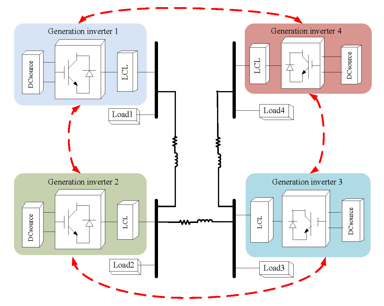
2.1. Microgrid Model

Consider the isolated microgrid consisting of n generation and m load buses. The generation bus presents an inverter which connects to a distributed power generation and a battery, and the load buses can be eliminated since the Kron-reduced network model is used here [24]. The power network of microgrid can be described by an undirected graph G = ( V , E ) , where the node set V = { 1 , 2 , , n } denotes the inverters and the edge set E = { ( i , j ) | i , j V } represents the transmission lines between inverters in microgrid. The set N i = { j | ( j , i ) E } describes all the inverters directly connected to inverter i by transmission line. Define D = { d i k } R n × m as the incidence matrix of graph G , where the d i k = 1 if node i is the positive end of edge k and d i k = 1 if node i is the negative end of edge k, otherwise d i k = 0 .
According to References [4,25], the dynamic of inverter at generation bus i is modeled as
d d t δ i = u i δ
τ V i d d t V i = V i + u i V ,
where the variable δ i and V i denote the voltage angle and voltage amplitude of inverter i respectively, the positive τ V i is the time constant. The controllers of inverter i in (1)–(2) are selected as
u i δ = ω d k P i ( P i m P i d p i )
u i V = V i d k Q i ( Q i m Q i d q i ) ,
where the constants V i d , ω d , P i d , Q i d , k P i and k Q i represent the desired voltage, desired frequency, active power setpoint, reactive power setpoint, frequency droop gains and voltage droop gains respectively, p i and q i are the additional control input. Noted that the measured active and reactive power of inverter i, which are labeled as P i m and Q i m respectively in (3) and (4), are obtained through the following filters
τ P i d d t P i m = P i m + P i
τ Q i d d t Q i m = Q i m + Q i ,
where the positive τ P i and τ Q i are time constants. The variable P i and Q i in (5) and (6) are the active and reactive power flow of inverter i represented as follows
P i = j N i | B i j | V i V j sin ( δ i δ j ) + P 0 i
Q i = | B i i | V i 2 j N i | B i j | V i V j cos ( δ i δ j ) + Q 0 i ,
where B i j is the susceptance of the transmission line between inverter i and j, B i i = B ^ i i + j N i B i j with the shunt susceptance B ^ i i , and the unknown constants P 0 i and Q 0 i approximate the terms involving the conductance of transmission lines.
In general τ V i τ P i τ Q i , and thus τ V i can be assumed to be 0. Combining (1)–(6) yields the following microgird model
d d t δ i = ω i
τ P i d d t ω i = ω i + ω d k P i ( P i P i d ) + u i P
τ Q i d d t V i = V i + V i d k Q i ( Q i Q i d ) + u i Q ,
where the control inputs u i P = k P i ( p i + τ P i d d t p i ) and u i Q = k Q i ( q i + τ Q i d d t q i ) . Since we only consider the optimal frequency regulation problem, the reactive power control inputs u i Q are assumed to be constant u ¯ i Q in this paper, and the active power control input u i P should be design later to implement the optimal frequency regulation.
Substituting (7) and (8) into (9)–(11) obtains the microgrid model in the following compact form
d d t η = D T ω
M P d d t ω = K P 1 ( ω ω d 1 ) D Γ ( V ) sin ( η ) + P 0 d + u P
M Q d d t V = K Q 1 ( V V d ) Θ ( V ) + | D | Γ ( V ) cos ( η ) + Q 0 d + u ¯ Q ,
where the vectors η = D T δ with δ = c o l ( δ i ) , ω = c o l ( ω i ) , V = c o l ( V i ) , V d = c o l ( V i d ) , P 0 d = c o l ( P i d P 0 i ) , Q 0 d = c o l ( Q i d Q 0 i ) , u P = c o l ( u i P ) , u ¯ Q = c o l ( u ¯ i Q ) , sin ( η ) = c o l ( s i n ( η i ) ) , cos ( η ) = c o l ( c o s ( η i ) ) and Θ ( V ) = c o l ( | B i i | V i 2 ) , and D is the incidence matrix of graph G defined before, the elements in matrix | D | are the absolute values of those in D, the matrix K P = d i a g ( k P i ) , K Q = d i a g ( k Q i ) , M P = K P 1 · d i a g ( τ P i ) , M Q = K Q 1 · d i a g ( τ Q i ) , Γ ( V ) = d i a g ( Γ ( V ) i i ) with Γ ( V ) i i = | B k l | V k V l if transmission line i is incident to inverter k and l. We set 1 = ( 1 , , 1 ) T to be the vector with appropriate dimension in the whole paper.

2.2. Communication Network

In order to implement the distributed optimal frequency regulation, each power generation inverter should transmit its own information to others through the communication network described by a graph G c = ( V , E c ) in the microgrid. The node set V is the same as that in power network G , and the edge set E c = { ( j , i ) | i f j i } where the symbol j i means that inverter j can transmit its own information to inverter i directly through communication network G c . The set N i c = { j | i f ( j , i ) E c } contains all the inverters which can communicate with inverter i, and its cardinal number is denoted as | N i c | . Define C = { c i j } R n × n as the adjacency matrix of graph G c , where c i j = 1 if ( i , j ) E c , otherwise c i j = 0 , and c i i = 0 . The Laplacian matrix of graph G c is given as L = d i a g ( d i ) C where d i = j N i c c i j . According to [7], the Laplacian matrix L is semi-positive definite since the graph G c is assumed to be undirected and connected. Mentioned that the edge sets E in power network G and E c in communication network G c can be different with each other.

2.3. Control Purpose

The frequency deviation at each inverter should be eliminated to ensure the stable operation of the isolated microgrid, which implies that the frequency ω i should achieve the desired value ω d for i = 1 , , n . It is known that the non-zero frequency deviation will occur when the active or reactive power setpoint P i d or Q i d changes caused by a disturbance. The purpose of frequency regulation is to restore the non-zero frequency deviation to zero by adjusting the active power control input u i P . Mathematically it requires that ω ¯ i = ω d ( i V ) where ω ¯ i is the frequency of inverter i at the steady state.
The steady state ( η ¯ , ω ¯ , V ¯ ) of system (12)–(14) under the given constant active power control input u ¯ i P satisfies
0 = D T ω ¯
0 = K P 1 ( ω ¯ ω d 1 ) D Γ ( V ¯ ) sin ( η ¯ ) + P 0 d + u ¯ P
0 = K Q 1 ( V ¯ V d ) Θ ( V ¯ ) + | D | Γ ( V ¯ ) cos ( η ¯ ) + Q 0 d + u ¯ Q .
Throughsome simple calculating based on (15)–(17), the frequency at steady state satisfies ω ¯ = ( ω d + ( P 0 d + u ¯ P ) T 1 1 T K P 1 1 ) 1 . This implies that ω ¯ i = ω d ( i V ) is equivalent to ( P 0 d + u ¯ P ) T 1 = 0 , which further means that the frequency deviation is eliminated if and only if the active power control input u P satisfies ( P 0 d + u P ) T 1 = 0 at the steady state. Furthermore, in order to coordinate the power generation inverters in an economically efficient way, the requirement in reducing the generation cost should also be considered. Considering the frequency restoration and economic efficiency simultaneously leads to the optimal frequency regulation problem given as
min u ¯ P C ( u ¯ P ) = min u ¯ P 1 2 ( u ¯ P ) T R u ¯ P = min u ¯ P i V 1 2 r i ( u ¯ i P ) 2
s . t . 0 = ( P 0 d + u ¯ P ) T 1 ,
where C ( u ¯ P ) is the generation cost function with the positive definite matrix R = d i a g ( r i ) for positive constants r i . The requirement of economic efficiency is reflected in (18), and that of frequency restoration is represented in (19).
Remark 1.
The constructed dynamic optimal frequency regulation should simultaneously achieve the two control purposes including restoring the frequency (i.e., restoring the active power balance) as shown in (19) and retaining the economic efficiency of power generation inverter as shown in (18). It is different with the onefold optimal dispatch problem where only the economic efficiency purpose is required.
The problem (18) and (19) can be addressed by the following distributed optimal frequency regulation constructed in Reference [16]
u i P ( t ) = ϕ i ( t ) r i
d d t ϕ i ( t ) = j N i c ( ϕ j ( t ) ϕ i ( t ) ) + ω i ( t ) ω d r i ,
where ϕ i is an internal variable of dynamic control law (20) and (21), and it is stored and computed in operation device at inverter i in practice.
However, it should be mentioned that each inverter needs to transmit its own information ϕ i to its neighbors j ( j N i c ) continuously through communication network G c under regulation (20) and (21). This is not practical since the information is transmitted discretely in a realistic communication network. Moreover, although there exists the discretization method for (20) and (21) according to the periodic sampled-data scheme, it may lead to unnecessary information transmission since the fixed sampling period is selected based on the worst case. The high data flows in a communication network brings the potential for harm, such as high costs, traffic congestion and limits on critical monitoring and protection functions, which may break the operation of distributed optimal frequency regulation and lead the breakdown of microgrid [26]. As a consequence, it is essential to communication-saving regulation method.
In this paper, the event-triggered mechanism based on the response of data ϕ i is introduced in the design of distributed optimal frequency regulation. Different from the continuous information transmission in regulation (20) and (21), the information of each inverter is transmitted discretely in the event-triggered regulation and the transmission time instant is determined by the proposed event-triggered mechanism. It aims to reduce the communication burden due to the on-demand transmission characteristics.

3. Main Results

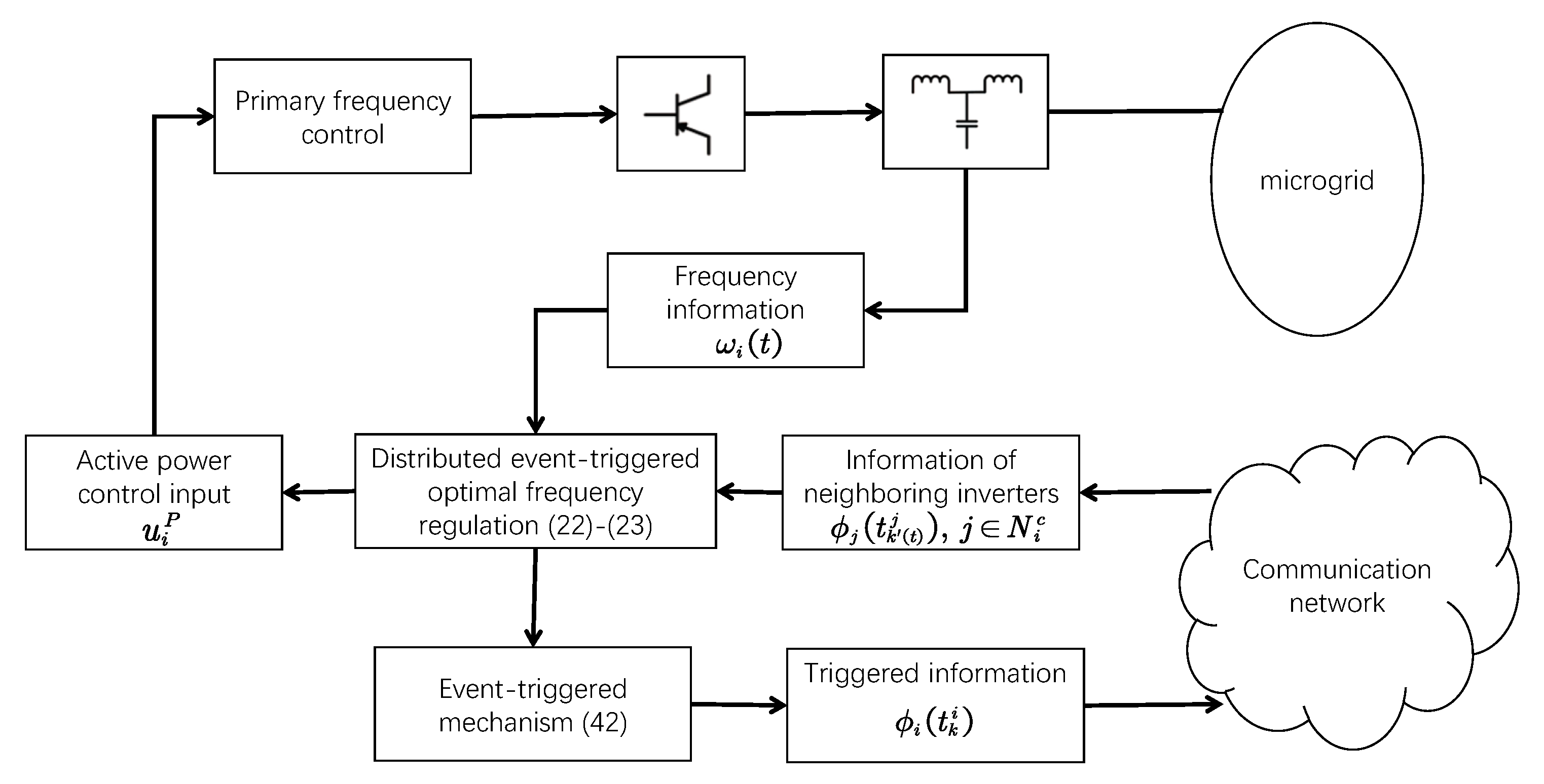
3.1. Distributed Event-Triggered Optimal Frequency Regulation

The triggering time sequence of inverter i determined by the event-triggered mechanism is denoted as { t 0 i , t 1 i , , t k i , } , where t 0 i < t 1 i <   < t k i <   . The distributed optimal frequency regulation for inverter i based on event-triggered sampling information is constructed as follows for t [ t k i , t k + 1 i )
u i P ( t ) = ϕ i ( t ) r i
d d t ϕ i ( t ) = j N i c ( ϕ j ( t k ( t ) j ) ϕ i ( t k i ) ) + ω i ( t ) ω d r i ,
where t k ( t ) j is the latest triggering time of inverter j before time t.
Denoting u P ( t ) = ( u 1 P ( t ) , , u n P ( t ) ) T , ϕ ( t ) = ( ϕ 1 ( t ) , , ϕ n ( t ) ) T and ϕ ^ ( t ) = ( ϕ 1 ( t k ( t ) 1 ) , , ϕ n ( t k ( t ) n ) ) T for t [ t k i , t k + 1 i ) , the regulation (22) and (23) can be written in the compact form as
u P ( t ) = R 1 ϕ ( t )
d d t ϕ ( t ) = L ϕ ^ ( t ) + R 1 ( ω ( t ) ω d 1 ) .
Remark 2.
The implementation of (22) and (23) at inverter i only requires the discrete event-triggered sampling information ϕ j ( t k ( t ) j ) transmitted from its neighbors instead of the continuous information ϕ j ( t ) . Inverter i remains the neighbors’ information ϕ j ( t k ( t ) j ) unchanged until the next event-triggered sampling information ϕ j ( t k ( t ) + 1 j ) is received from inverter j. This implies that only the discrete event-triggered sampling information is transmitted through the communication network under the regulation (22) and (23), which can reduce the communication burdens compared with (20) and (21).
According to Lagrange multiplier method, the optimal solution of problem (18) and (19) is u ¯ P = R 1 ϕ ¯ with ϕ ¯ = 1 1 T P 0 d 1 T R 1 1 . The aim of distributed optimal frequency regulation is to maintain the stability of steady state ( ω d 1 , η ¯ , V ¯ , ϕ ¯ ) for the closed-loop system (12)–(14) and (24) and (25). In order to certify the effectiveness of regulation (22) and (23), the triggering time sequence { t 0 i , t 1 i , , t k i , } of each inverter i needs to be selected. This is determined by the event-triggered mechanism which will be constructed in the following sections.

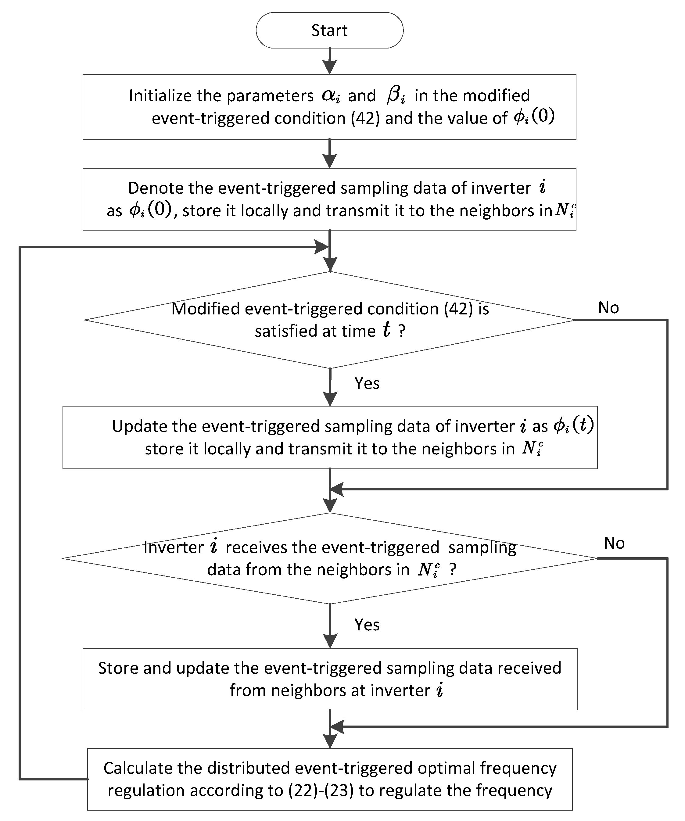
3.2. Distributed Event-Triggered Mechanism Based on Response Data

Construct the event-triggered condition of inverter i based on response data of ϕ i and ϕ j ( j N i c ) as follows for t [ t k i , t k + 1 i )
e i 2 ( t ) > α i 4 | N i c | j N i c ( ϕ j ( t k ( t ) j ) ϕ i ( t k i ) ) 2 ,
where α i ( 0 , 1 ) is a constant and the measurement error e i ( t ) is defined as
e i ( t ) = ϕ i ( t k i ) ϕ i ( t ) .
When the event-triggered condition (26) is satisfied for t > t k i , inverter i will label the time t as t k + 1 i and transmit its own sampling information ϕ i ( t k + 1 i ) to its neighbors in N i c . The triggering time sequence { t 0 i , t 1 i , , t k i , } is determined by the event-event-triggered condition (26) as
t k + 1 i = inf t > t k i { t | e i 2 ( t ) > α i 4 | N i c | j N i c ( ϕ j ( t k ( t ) j ) ϕ i ( t k i ) ) 2 } .
Remark 3.
The condition (26) can be seen as an ‘event’ in the mechanism. The ‘event’ occurs if and only if the condition (26) is satisfied. The occurrence of ‘event’ triggers a series of actions, which include labeling the triggering time instant t k + 1 i , updating and transmitting the data ϕ i ( t k + 1 i ) to neighbors through the communication network. It is noted that the above actions do not execute if the ‘event’ (26) does not occur.
Remark 4.
The conventional distributed optimal frequency regulation (20) and (21) can make the discrete implementation based on the periodic sampling mechanism as follows for t [ k h , ( k + 1 ) h )
u i P ( t ) = ϕ i ( t ) r i
d d t ϕ i ( t ) = j N i c ( ϕ j ( k h ) ϕ i ( k h ) ) + ω i ( t ) ω d r i ,
where the non-negative integer k is the sampling number, and the positive constant h is the sampling period. The information transmission period of (28) and (29) is the constant h. In order to maintain the system stability, the period h is fixed based on the worst case usually, which increases the conservatism and makes the unnecessary information transmission. Instead, the information transmission period ( t k + 1 i t k i ) of the event-triggered regulation (22) and (23) is determined by the proposed event-triggered mechanism (26), which is adjusted adaptively according to the system’s state. It leads to fewer communication burdens compared with the periodic sampling mechanism.
The following candidate Lyapunov function will be used to prove the stability of closed-loop system.
U ( ω , η , V , ϕ ) = ( ω ω d 1 ) T M P ( ω ω d 1 ) 1 T Γ ( V ) cos ( η ) + 1 T Γ ( V ¯ ) cos ( η ¯ ) ( Γ ( V ¯ ) sin ( η ¯ ) ) T ( η η ¯ ) + 1 T K Q 1 ( V V ¯ ) + 1 2 1 T ( Θ ( V ) Θ ( V ¯ ) ) ( K Q 1 V d + Q 0 d + u ¯ Q ) T ( ln ( V ) ln ( V ¯ ) ) + 1 2 ( ϕ ϕ ¯ ) T ( ϕ ϕ ¯ ) ,
where ln ( V ) = c o l ( l n ( V i ) ) and ln ( V ¯ ) = c o l ( l n ( V ¯ i ) ) .
Assumption 1.
The steady state ( ω d 1 , η ¯ , V ¯ , ϕ ¯ ) satisfies ( 2 U 2 V 2 U V η ( 2 U 2 η ) 1 2 U η V ) | ω = ω d 1 , η = η ¯ , V = V ¯ , ϕ = ϕ ¯ > 0 .
Assumption 1 is quoted from Reference [16] to ensure that the steady-state ( ω d 1 , η ¯ , V ¯ , ϕ ¯ ) is a strict local minimum point of function U ( ω , η , V , ϕ ) .
Theorem 1.
The distributed optimal frequency regulation (22) and (23) with the event-triggered condition (26) guarantees the solutions of a closed-loop system (12)–(14) and (24) and (25), which start in a neighborhood of ( ω d 1 , η ¯ , V ¯ , ϕ ¯ ) , to asymptotically converge to the new steady-state ( ω d 1 , η ˜ , V ˜ , ϕ ¯ ) , where the constants η ˜ and V ˜ satisfy V U | η = η ˜ , V = V ˜ = 0 .
Proof. 
The derivation of function U with respect to time t along the solution of closed-loop system (12)–(14) and (24)–(25) as
d d t U = ( ω ω d 1 ) T K P 1 ( ω ω d 1 ) ( V U ) T M Q 1 d i a g ( V ) ( V U ) ( ϕ ϕ ¯ ) T L ( ϕ ^ ϕ ¯ ) ,
where M Q d d t V = d i a g ( V ) V U is used here.
Since the graph G c is undirected and connected, we have
( ϕ ϕ ¯ ) T L ( ϕ ^ ϕ ¯ ) = ϕ T L ϕ ^ = i = 1 n ϕ i ( t ) j = 1 n l i j ϕ j ( t k ( t ) j ) = i = 1 n ϕ i ( t k i ) e i ( t ) j = 1 n l i j ϕ j ( t k ( t ) j ) = i = 1 n ϕ i ( t k i ) j = 1 n l i j ϕ j ( t k ( t ) j ) i = 1 n e i ( t ) j = 1 n l i j ϕ j ( t k ( t ) j ) 1 2 i = 1 n j = 1 n l i j ϕ i ( t k i ) ϕ j ( t k ( t ) j ) 2 + i = 1 n j = 1 , j i n l i j e i 2 ( t ) + l i j 4 ϕ i ( t k i ) ϕ j ( t k ( t ) j ) 2 = i = 1 n | N i c | e i 2 ( t ) i = 1 n j = 1 n l i j 4 ϕ i ( t k i ) ϕ j ( t k ( t ) j ) 2 ,
where Young’s inequality is used.
For t [ t k i , t k + 1 i ) , the event-event-triggered condition (26) implies that
e i 2 ( t ) α i 4 | N i c | j N i c ( ϕ j ( t k ( t ) j ) ϕ i ( t k i ) ) 2 .
Submitting (32) and (33) into (31) yields
d d t U ( ω ω d 1 ) T K P 1 ( ω ω d 1 ) ( V U ) T M Q 1 d i a g ( V ) ( V U ) i = 1 n 1 α i 4 j N i c ϕ i ( t k i ) ϕ j ( t k ( t ) j ) 2 ( ω ω d 1 ) T K P 1 ( ω ω d 1 ) 1 α m a x 2 ϕ ^ T L ϕ ^ ( V U ) T M Q 1 d i a g ( V ) ( V U )
where α m a x = max { α 1 , , α n } .
Let e ( t ) = ( e 1 ( t ) , . . . , e n ( t ) ) T and N m i n c = min { | N 1 c | , , | N n c | } , we have
( ϕ ϕ ¯ ) T L ( ϕ ϕ ¯ ) = ( ϕ ^ e ) T L ( ϕ ^ e ) 2 ϕ ^ T L ϕ ^ + 2 L e 2 ( 2 + α m a x L N m i n c ) ϕ ^ T L ϕ ^ ,
where (33) is used.
Combining (34) and (35) yields
d d t U ( ω ω d 1 ) T K P 1 ( ω ω d 1 ) c 1 ( ϕ ϕ ¯ ) T L ( ϕ ϕ ¯ ) ( V U ) T M Q 1 d i a g ( V ) ( V U ) ,
where the positive constant c 1 = N m i n c ( 1 α m a x ) 2 ( 2 N m i n c + L α m a x ) .
Reminder that the matrix M Q 1 d i a g ( V ) is positive definite since the voltage V i is always positive. According to the fact that ( ω d 1 , η ¯ , V ¯ , ϕ ¯ ) is a strict local minimum point of function U as mentioned before and d d t U 0 as shown in (36), the stability of closed-loop system can be guaranteed by the help of Lasalle’s invariance principle. Equation (36) implies that the solution of closed-loop system converges into the set S = { ( ω , η , V , ϕ ) | ω = ω d 1 , V U = 0 , ϕ = ϕ ¯ + a ( t ) 1 } . V U = 0 means that the variable V is constant since M Q d d t V = d i a g ( V ) V U , and we denote the constant V as V ˜ . Moreover, the variable η is constant in set S since d d t η = D T ω d 1 = 0 , and we denote the constant η as η ˜ . Let the steady state ω ¯ = ω d 1 and u ¯ P = R 1 ϕ ¯ in (16), we get
0 = D Γ ( V ¯ ) sin ( η ¯ ) + P 0 d R 1 ϕ ¯ .
Furthermore, the state in set S satisfies
0 = D Γ ( V ˜ ) sin ( η ˜ ) + P 0 d R 1 ( ϕ ¯ + a ( t ) 1 ) .
Combining (37) and (38) yields
0 = D Γ ( V ˜ ) sin ( η ˜ ) + D Γ ( V ¯ ) sin ( η ¯ ) a ( t ) R 1 1 .
Multiplying both sides of (39) by 1 T obtains a ( t ) 1 T R 1 1 = 0 . This implies that a ( t ) 0 since matrix R is positive definite, which indicates ϕ = ϕ ¯ in set S. This concludes the proof. □
The dynamical scenario of optimal frequency regulation can be depicted as follows. The microgrid is operated at the initial steady state which satisfies the problem (18) and (19) at the initial stage. When some disturbance occurs in the microgrid, the active or reactive power setpoints P i d or Q i d changes, and the initial steady state can not satisfy the problem (18) and (19) anymore under these new setpoints, which brakes the frequency stability and economic efficiency of the microgrid. Theorem 1 states that the distributed optimal frequency regulation (22) and (23) with the event-triggered condition (26) is able to drive the system trajectory to the new steady state ( ω d 1 , η ˜ , V ˜ , ϕ ¯ ) . Mentioned that ( ω d 1 , η ˜ , V ˜ , ϕ ¯ ) is the optimal solution of problem (18) and (19) under the new setpoints P i d and Q i d since u ¯ P = R 1 ϕ ¯ with ϕ ¯ = 1 1 T P 0 d 1 T R 1 1 . This implies that the frequency is restored and the economic efficiency is maintained under the action of (22) and (23), which demonstrates the effectiveness of the event-triggered regulation method.
Theorem 2.
The inter-event time interval t k + 1 i t k i of event-triggered condition (26) is lower bounded as
t k + 1 i t k i > 1 M i α i 4 | N i c | j N i c ( ϕ j ( t k ( t k + 1 i ) j ) ϕ i ( t k i ) ) 2 1 2 ,
where M i is a positive constant.
Proof. 
Since the continuously differentiable function j N i c ( ϕ j ( t ) ϕ i ( t ) ) + ω i ( t ) ω d r i asymptotically converges to 0 as shown in Theorem 1, for t [ t k i , t k + 1 i ) we have
d d t | e i ( t ) | | d d t e i ( t ) | = | d d t ϕ i ( t ) | = | j N i c ( ϕ j ( t k ( t ) j ) ϕ i ( t k i ) ) + ω i ( t ) ω d r i | M i ,
where M i is some positive constant. (41) implies | e i ( t ) | | e i ( t k i ) | M i ( t t k i ) , and thus | e i ( t ) | M i ( t t k i ) for t [ t k i , t k + 1 i ) . Since the triggering time t = t k + 1 i occurs when e i ( t ) > α i 4 | N i c | j N i c ( ϕ j ( t k ( t ) j ) ϕ i ( t k i ) ) 2 1 2 , we have e i ( t k + 1 i ) > α i 4 | N i c | j N i c ( ϕ j ( t k ( t k + 1 i ) j ) ϕ i ( t k i ) ) 2 1 2 . This together with the fact t t k i | e i ( t ) | M i for t [ t k i , t k + 1 i ) yields (40). □
Zeno behavior means infinite times of event triggering in a finite time interval, which is impractical for engineering application and should be avoided in the construction of event-triggered mechanism. Theorem 2 shows that the lower bound of inter-event time interval t k + 1 i t k i of event-triggered condition (26) is strict positive, however, this lower bound converges to zero when the control purpose trends to be accomplished since lim t + 1 M i α i 4 | N i c | j N i c ( ϕ j ( t k ( t k + 1 i ) j ) ϕ i ( t k i ) ) 2 1 2 = 0 for all i. This may cause a probable high communication frequency, and the event-triggered condition (26) should be modified to address this issue in the following section.

3.3. Modified Distributed Event-Triggered Mechanism Based on Response Data

In order to guarantee the uniform positive lower bound of inter-event time interval, the event-triggered condition (26) is modified as (42) by introducing the positive constant β i , and the modified distributed event-triggered mechanism (42) is also based on the response data of ϕ i and ϕ j ( j N i c )
e i 2 ( t ) > 1 | N i c | α i 4 j N i c ( ϕ j ( t k ( t ) j ) ϕ i ( t k i ) ) 2 + β i .
The triggering time sequence { t 0 i , t 1 i , , t k i , } determined by the modified event-triggered condition (42) is given as
t k + 1 i = inf t > t k i { t | e i 2 ( t ) > 1 | N i c | α i 4 j N i c ( ϕ j ( t k ( t ) j ) ϕ i ( t k i ) ) 2 + β i } .
Theorem 3.
The distributed optimal frequency regulation (22) and (23) with the modified event-triggered condition (42) guarantees the solutions of closed-loop system (12)–(14) and (24)–(25), which start in a neighborhood of ( ω d 1 , η ¯ , V ¯ , ϕ ¯ ) , to asymptotically converge into an arbitrary small neighborhood of the new steady-state ( ω d 1 , η ˜ , V ˜ , ϕ ¯ ) , where the constants η ˜ and V ˜ satisfy V U | η = η ˜ , V = V ˜ = 0 . Moreover, the inter-event time intervals is lower bounded as t k + 1 i t k i > β i 1 2 M ˜ i | N i c | 1 2 where M ˜ i is some positive constant, and Zeno behavior can be avoided.
Proof. 
By a similar analysis in the proof of Theorem 1, the derivation of function U with respect to time t along the solution of closed-loop system satisfies
d d t U ( ω ω d 1 ) T K P 1 ( ω ω d 1 ) ( V U ) T M Q 1 d i a g ( V ) ( V U ) c 1 ( ϕ ϕ ¯ ) T L ( ϕ ϕ ¯ ) + c 2 i = 1 n β i ,
where the positive constants c 1 = N m i n c ( 1 α m a x ) 2 ( 2 N m i n c + L α m a x ) and c 2 = 2 L c 1 N m i n c + 1 .
Inequation (43) demonstrates that the solution of closed-loop system converges into the set S ˜ = { ( ω , η , V , ϕ ) | ( ω ω d 1 ) T K P 1 ( ω ω d 1 ) + ( V U ) T M Q 1 d i a g ( V ) ( V U ) + c 1 ( ϕ ϕ ¯ ) T L ( ϕ ϕ ¯ ) c 2 i = 1 n β i } . Based on the analysis in the proof of Theorem 1, this implies that the solution of closed-loop system converges into an arbitrary small neighborhood of the new steady state ( ω d 1 , η ˜ , V ˜ , ϕ ¯ ) by selecting the parameter β i sufficient small.
The lower bound of inter-event time intervals of event-triggered condition (42) can be obtained by a similar analysis in the proof of Theorem 2. Since this lower bound is uniform strict positive, inverter i could not produce infinite times of triggering in any finite time interval, which indicates the exclusion of Zeno behavior. □
Figure 1 illustrates the control structure at the ith power generation inverter in the microgrid. The flowchart of the proposed distributed optimal frequency regulation algorithm (22) and (23) with the modified event-triggered condition (42) is shown in Figure 2.
Remark 5.
Compared the event-triggered mechanism (26) with the modified one (42), the difference is the introduction of positive constant β i . The role of β i is to obtain the uniform positive lower bound β i 1 2 M ˜ i | N i c | 1 2 of inter-event time interval. This lower bound prevents the inter-event time interval from converging to zero, and thus Zeno behavior is excluded.
Remark 6.
Different from the asymptotically stability result in Theorem 1 under an event-triggered mechanism (26), the solution of closed-loop system can not converge to the desired steady state accurately under the modified event-triggered condition (42) as shown in Theorem 3. However, it still meet the requirement of optimal frequency regulation problem since these state variables are allowed to fluctuate in an allowable range around the steady state in a practical isolated microgrid.
Remark 7.
The proof of Theorem 3 shows that the parameter β i reflects the trade-off between control performance and communication resource limitation. The reduction of β i could shrink the fluctuation range around steady state since the solution of system converges into the set S ˜ = { ( ω , η , V , ϕ ) | ( ω ω d 1 ) T K P 1 ( ω ω d 1 ) + ( V U ) T M Q 1 d i a g ( V ) ( V U ) + c 1 ( ϕ ϕ ¯ ) T L ( ϕ ϕ ¯ ) c 2 i = 1 n β i } , however, this reduction results in higher triggering frequency and requires more communication resource since the lower bound of inter-event time interval is estimated as β i 1 2 M ˜ i | N i c | 1 2 , and vice versa.

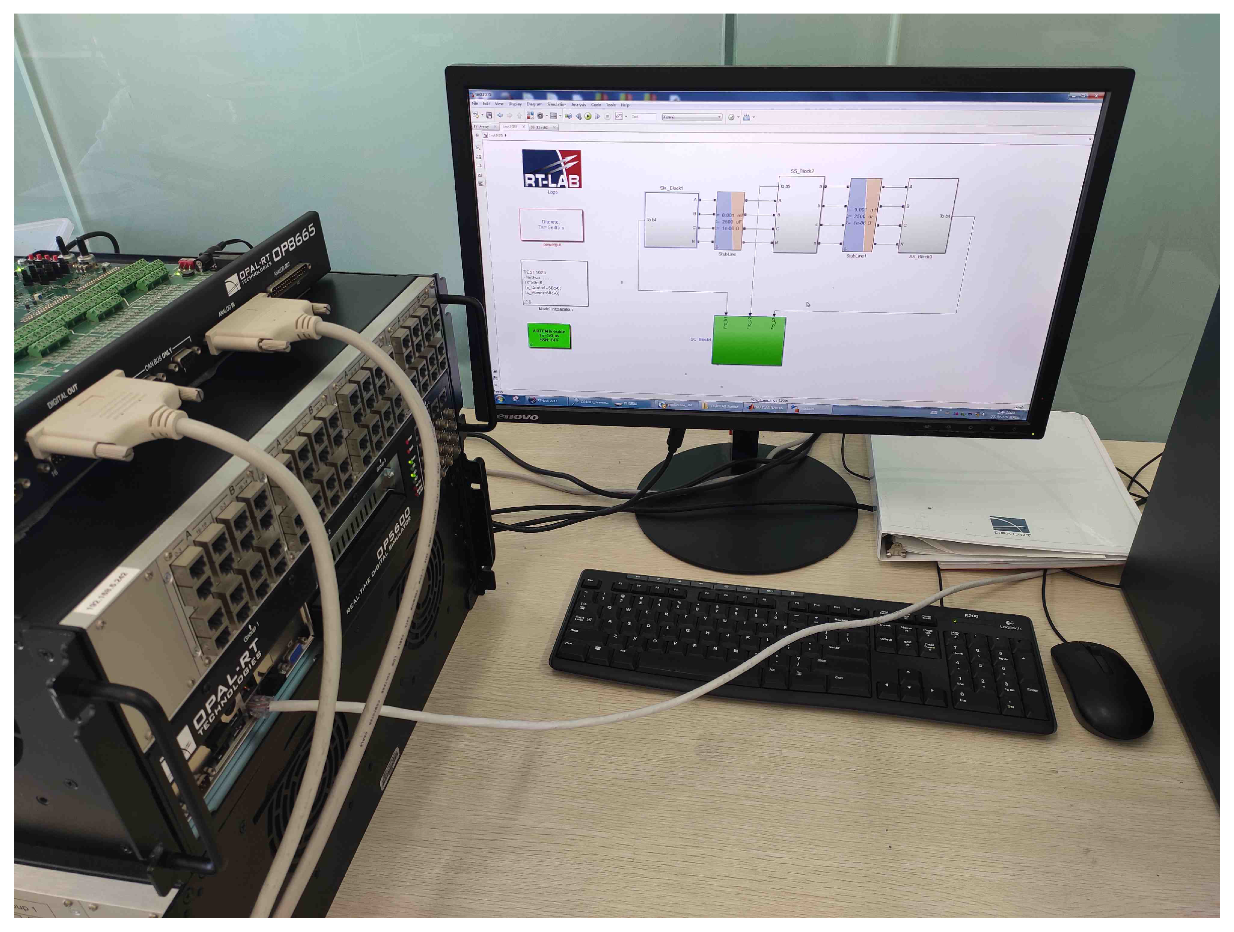
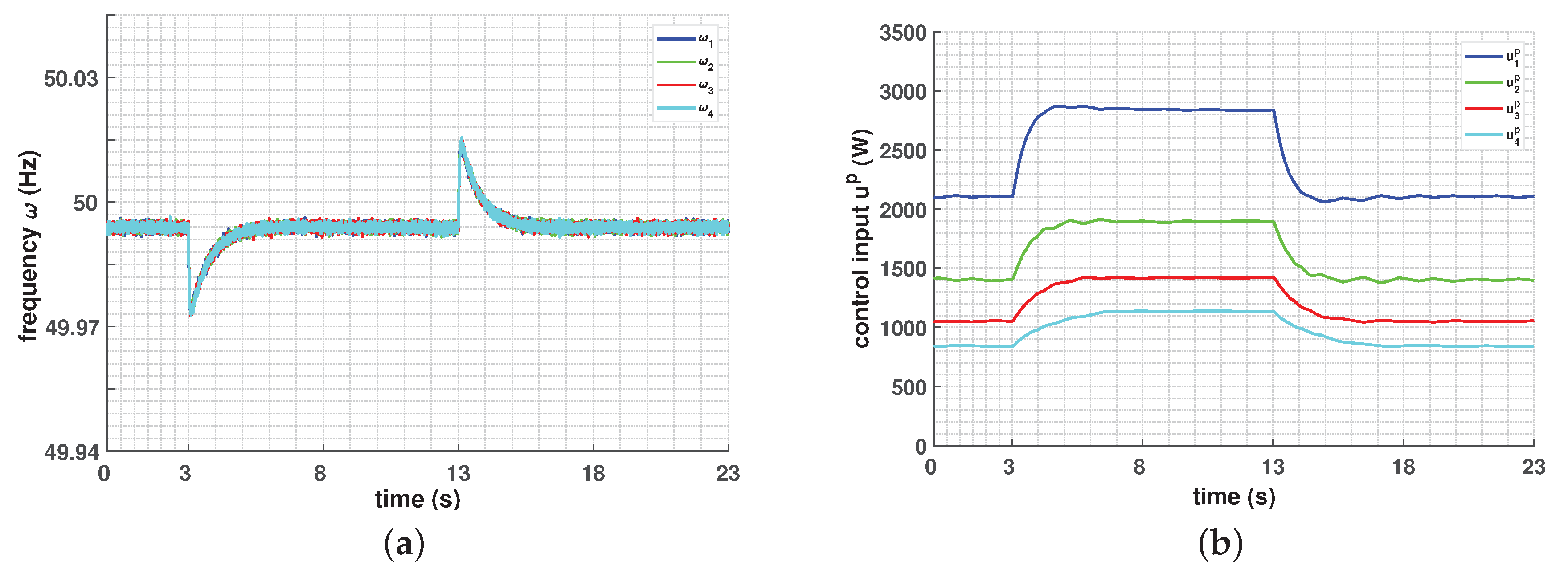
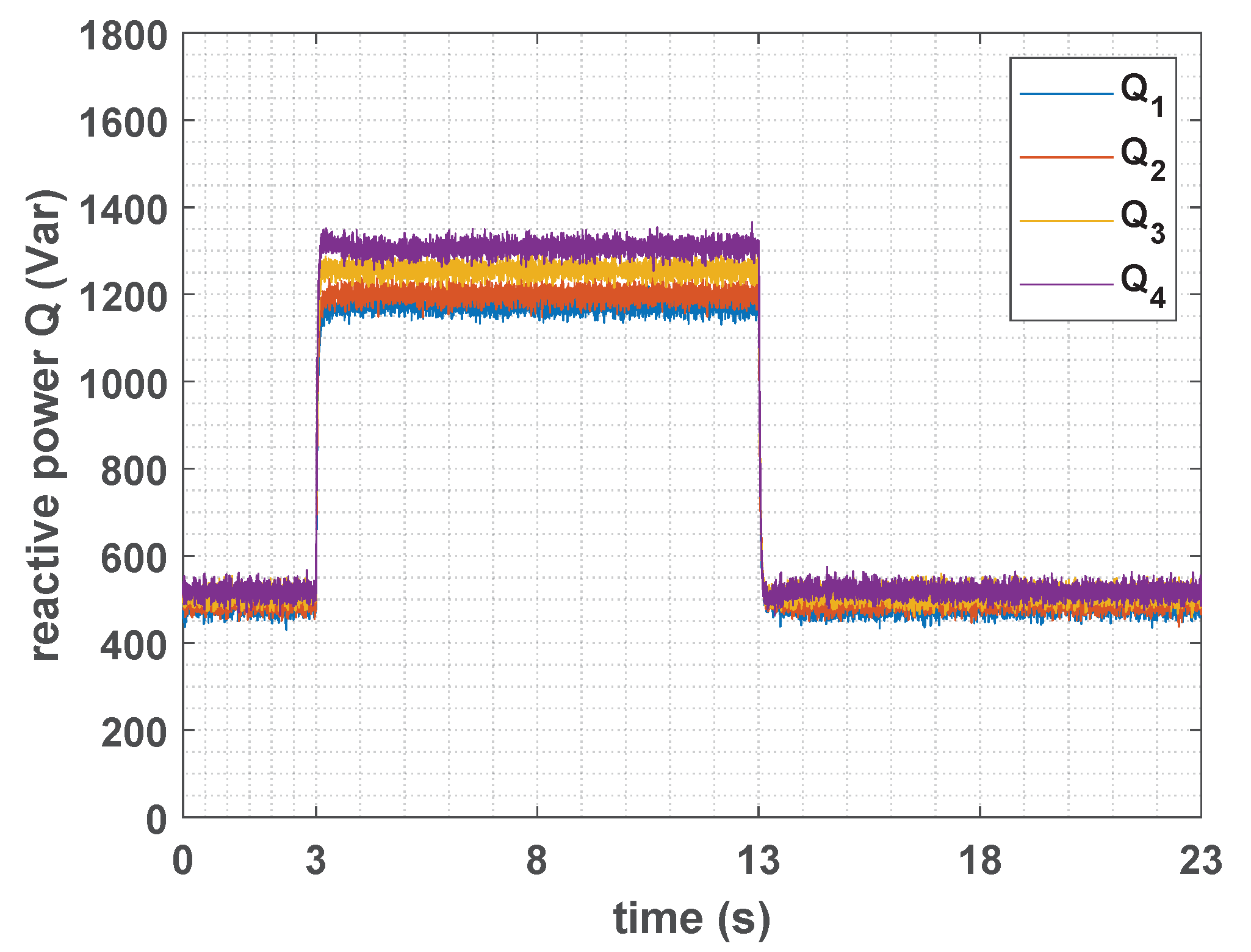
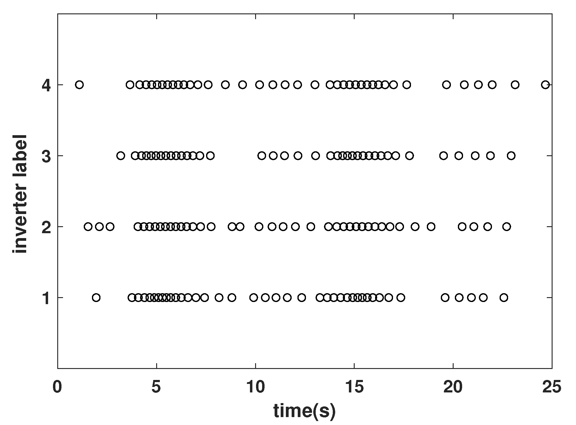
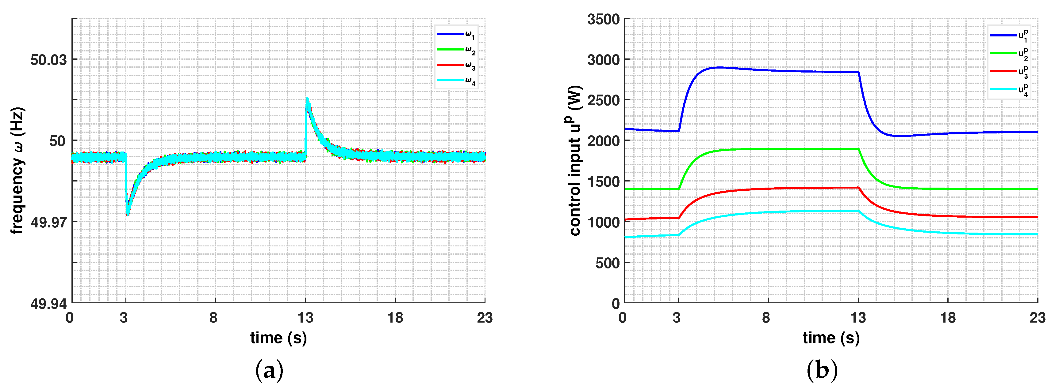
4. Experimental Results

The effectiveness of distributed optimal frequency regulation (22) and (23) with event-triggered condition (42) is experimentally verified on a test microgrid containing 4 power generation inverters in a HIL system presented in Figure 3, where the red dashed arrow lines denote the edges in communication network G c . The HIL is an OPAL-RT real-time digital simulator. The platform is shown in Figure 4. Three of the inverters are downloaded into OP5600 number one (shown at top of the screen) and the fourth one is incorporated into OP5600 number two (shown at the bottom of the screen). The OP8665 with DSP 28335 is used to generate the PWM signals according to the proposed algorithm. The plots are collected through the digital-to-analog channels of the OPAL-RT. The desired frequency ω d = 50 H z and the matrix R in (18) is chosen as d i a g ( 1 , 1.5 , 2 , 2.5 ) . The parameters in the event-triggered mechanism (42) are given as α i = 0.8 and β i = 0.003 for i = 1 , 2 , 3 , 4 . Similar to [16], the reactive power control input is setting as
u i Q ( t ) = μ i ( t ) d d t μ i ( t ) = j N i c ( μ j ( t ) μ i ( t ) ) + ( V i ( t ) V i d )
to represent the response of reactive power at each power generation inverter.
Case A. Robustness against load change
The microgrid is initially at the steady state with total active power demand of 5.5 kW and reactive power demand 2 kVar, and then these demands are increased by 3 kW and 3 kVar respectively at 3 s and then return to the initial values at 13 s for some load disturbances in this case. The responses of frequency and active power control input under distributed optimal frequency mechanism (22)–(23) with event-triggered mechanism (42) are shown in Figure 5a,b. It can be seen that these two types of variables are fluctuated in a small neighborhood of the steady state under the action of distributed event-triggered optimal frequency mechanism. The frequencies of all inverters converge into an allowable range of the desired value 50 Hz (i.e., 314 rad/s) and the active power control inputs converge to the values which satisfy the optimal problem (18)–(19). It shows that the optimal frequency regulation purpose can be achieved under the constructed event-triggered regulation. Figure 6 shows the reactive power balance between supply and demand. Figure 7 illustrates the triggering time instants of the four inverters, where the unequal triggering periods demonstrates the on-demand transmission characteristic of event-triggered mechanism.
In contrast, the response of frequency and active power control input under regulation (28) and (29) based on periodic sampling mechanism are given in Figure 8a,b by selecting the sampling period as h = 0.2 s. Comparing Figure 5 with Figure 8 obtains that the control performances under these two types of mechanism are nearly the same. However, Table 1 and Figure 9 illustrate that the sampling number under event-triggered mechanism is lower than that under periodic sampling mechanism, which implies that less communication frequency is required for the proposed event-triggered optimal frequency regulation method compared with the periodic sampled one. This demonstrates the superiority of the event-triggered mechanism in reducing communication burdens.
Case B. Plug-and-play physical capability
The microgrid is initially at the steady state with total active power demand 7.3 kW and reactive power demand 3 kVar, and then the generation inverter 4 is plugged out the test microgrid at 3 s and then plugged into it at 13 s in this case. Figure 10, Figure 11 and Figure 12 demonstrates the effectiveness of proposed event-triggered regulation on plug-and-play operation and the ability of demand-transmission character for the constructed event-triggered mechanism. The results of regulation (28)–(29) based on periodic sampling mechanism with the fixed sampling period h = 0.2 s are given in Figure 13 by comparison. Mentioned that the similar control performance can be obtained under these two types of regulation, however, Table 2 and Figure 14 imply that less communication is required for the regulation under event-triggered mechanism.

5. Conclusions

The distributed optimal frequency regulation for multiple power generations in an isolated microgrid under limited communication resource is considered in this paper, which can restore the frequency and retain the economic efficiency of a microgrid simultaneously when some disturbances occur. The event-triggered mechanism is introduced in the construction of regulation algorithm, and each power generation inverter only need to transmit its own information through communication network when the event-triggered condition is satisfied. It can be expected that less transmitted information is needed to implement the regulation and the communication burden can be reduced. Our future work will consider the construction of distributed event-triggered frequency regulation for multiple power generations in an isolated microgrid under non-ideal data transmission case in practical communication networks. Moreover, the event-triggered frequency regulation method under large disturbance in an isolated microgrid will also be studied.

Author Contributions

S.X., H.S., B.Z. and J.Y. formulated the microgrid model and control purpose. S.W., J.C. and C.D. studied the methodology and implemented the experimental simulation. All authors have read and agreed to the published version of the manuscript.

Funding

This research has been supported by the National Natural Science Foundation of China (51977197, U1766202, 51777195), Fundamental and Forecast Projects of State Grid Corporation of China “Theory Research on Response Driven Comprehensive Defense Control of Power System” (XT71-18-014), Young Elite Scientists Sponsorship Program by CAST (YESS20160157) and CSEE (JLB-2017-305).

Conflicts of Interest

The authors declare no conflict of interest.

References

  1. Atawi, I.E.; Kassem, A.M.; Zaid, S.A. Modeling, Management, and Control of an Autonomous Wind/Fuel Cell Micro-Grid System. Processes 2019, 7, 85. [Google Scholar] [CrossRef] [Green Version]
  2. Parhizi, S.; Lotfi, H.; Khodaei, A.; Bahramirad, S. State of the art in research on microgrids: A review. IEEE Access 2015, 3, 890–925. [Google Scholar] [CrossRef]
  3. Krishna, A.; Schiffer, J.; Raisch, J. A consensus-based control law for accurate frequency restoration and power sharing in microgrids in the presence of clock drifts. In Proceedings of the IEEE European Control Conference (ECC), Limassol, Cyprus, 12–15 June 2018; pp. 2575–2580. [Google Scholar]
  4. Lopes, J.A.P.; Moreira, C.L.; Madureira, A.G. Defining control strategies for MicroGrids islanded operation. IEEE Trans. Power Syst. 2006, 21, 916–924. [Google Scholar] [CrossRef] [Green Version]
  5. Tan, K.T.; Peng, X.Y.; So, P.L.; Chu, Y.C.; Chen, M.Z.Q. Centralized Control for Parallel Operation of Distributed Generation Inverters in Microgrids. IEEE Trans. Smart Grid 2012, 3, 1977–1987. [Google Scholar] [CrossRef] [Green Version]
  6. Liu, S.; Wang, X.; Liu, P.X. Impact of Communication Delays on Secondary Frequency Control in an Islanded Microgrid. IEEE Trans. Ind. Electron. 2015, 62, 2021–2031. [Google Scholar] [CrossRef]
  7. Olfati-Saber, R.; Murray, R.M. Consensus problems in networks of agents with switching topology and time-delays. IEEE Trans. Autom. Control 2004, 49, 1520–1533. [Google Scholar] [CrossRef] [Green Version]
  8. Ren, W.; Beard, R.W. Consensus seeking in multiagent systems under dynamically changing interaction topologies. IEEE Trans. Autom. Control 2005, 50, 655–661. [Google Scholar] [CrossRef]
  9. Xingli, Z.; Ning, W. Multi-agent consensus algorithm-based optimal power dispatch for islanded multi-microgrids. Processes 2019, 7, 679. [Google Scholar] [CrossRef] [Green Version]
  10. Shafiee, Q.; Guerrero, J.M.; Vasquez, J.C. Distributed secondary control for islanded microgrids—A novel approach. IEEE Trans. Power Electron. 2013, 29, 1018–1031. [Google Scholar] [CrossRef] [Green Version]
  11. Simpson-Porco, J.W.; Dorfler, F.; Bullo, F. Synchronization and power sharing for droop-controlled inverters in islanded microgrids. Automatica 2013, 49, 2603–2611. [Google Scholar] [CrossRef] [Green Version]
  12. Bouattour, H.; Simpson-Porco, J.W.; Dörfler, F.; Bullo, F. Further results on distributed secondary control in microgrids. In Proceedings of the 52nd IEEE Conference on Decision and Control, Florence, Italy, 10–13 December 2013; pp. 1514–1519. [Google Scholar]
  13. Guo, F.; Wen, C.; Mao, J.; Song, Y.D. Distributed Secondary Voltage and Frequency Restoration Control of Droop-Controlled Inverter-Based Microgrids. IEEE Trans. Ind. Electron. 2015, 62, 4355–4364. [Google Scholar] [CrossRef]
  14. Pilloni, A.; Pisano, A.; Usai, E. Robust finite-time frequency and voltage restoration of inverter-based microgrids via sliding-mode cooperative control. IEEE Trans. Ind. Electron. 2017, 65, 907–917. [Google Scholar] [CrossRef]
  15. Cai, H.; Hu, G.; Lewis, F.L.; Davoudi, A. A Distributed Feedforward Approach to Cooperative Control of AC Microgrids. IEEE Transa. Power Syst. 2016, 31, 4057–4067. [Google Scholar] [CrossRef]
  16. Trip, S.; Bürger, M.; De Persis, C. An internal model approach to frequency regulation in inverter-based microgrids with time-varying voltages. In Proceedings of the 53rd IEEE Conference on Decision and Control, Los Angeles, CA, USA, 15–17 December 2014; pp. 223–228. [Google Scholar]
  17. Lai, J.; Lu, X.; Yu, X.; Monti, A.; Zhou, H. Distributed voltage regulation for cyber-physical microgrids with coupling delays and slow switching topologies. IEEE Trans. Syst. Man Cybern. Syst. 2019. [Google Scholar] [CrossRef]
  18. Lai, J.; Lu, X.; Yu, X. Stochastic Distributed Frequency and Load Sharing Control for Microgrids with Communication Delays. IEEE Syst. J. 2019, 13, 4269–4280. [Google Scholar] [CrossRef]
  19. Yue, D.; Tian, E.; Han, Q.L. A Delay System Method for Designing Event-Triggered Controllers of Networked Control Systems. IEEE Trans. Autom. Control 2013, 58, 475–481. [Google Scholar] [CrossRef]
  20. Wang, X.; Lemmon, M. Event-Triggering in Distributed Networked Control Systems. IEEE Trans. Autom. Control 2011, 56, 586–601. [Google Scholar] [CrossRef] [Green Version]
  21. Tahir, M.; Mazumder, S.K. Self-Triggered Communication Enabled Control of Distributed Generation in Microgrids. IEEE Trans. Ind. Inf. 2015, 11, 441–449. [Google Scholar] [CrossRef]
  22. Fan, Y.; Hu, G.; Egerstedt, M. Distributed Reactive Power Sharing Control for Microgrids with Event-Triggered Communication. IEEE Trans. Control Syst. Technol. 2017, 25, 118–128. [Google Scholar] [CrossRef]
  23. Fan, Y.; Zhang, C.; Song, C. Sampling-based self-triggered coordination control for multi-agent systems with application to distributed generators. Int. J. Syst. Sci. 2018, 49, 3048–3062. [Google Scholar] [CrossRef]
  24. Dorfler, F.; Bullo, F. Synchronization and transient stability in power networks and nonuniform Kuramoto oscillators. SIAM J. Control Optim. 2012, 50, 1616–1642. [Google Scholar] [CrossRef] [Green Version]
  25. Schiffer, J.; Ortega, R.; Astolfi, A.; Raisch, J.; Sezi, T. Conditions for stability of droop-controlled inverter-based microgrids. Automatica 2014, 50, 2457–2469. [Google Scholar] [CrossRef] [Green Version]
  26. Ding, L.; Han, Q.L.; Zhang, X.M. Distributed secondary control for active power sharing and frequency regulation in islanded microgrids using an event-triggered communication mechanism. IEEE Trans. Ind. Inform. 2018, 15, 3910–3922. [Google Scholar] [CrossRef]
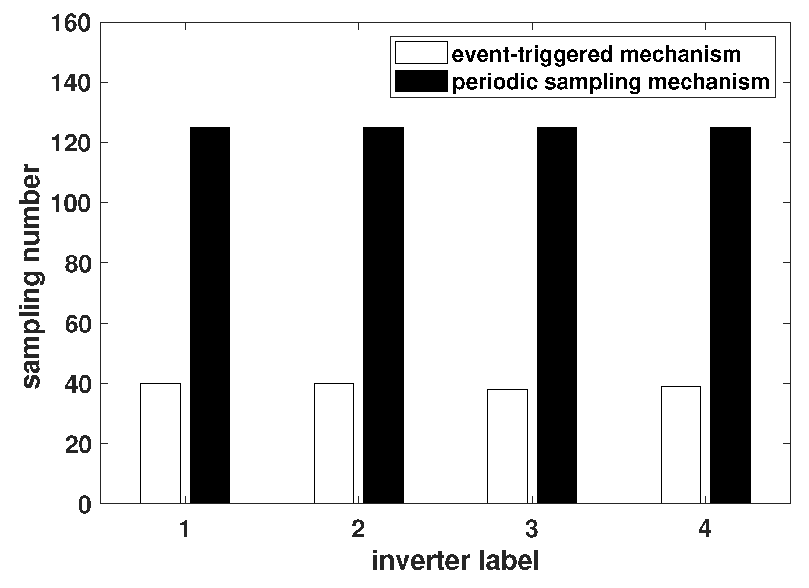
Figure 1. The diagram of control structure at the ith power generation inverter in microgrid.
Processes 08 00169 g001
Figure 2. The flowchart of distributed optimal frequency regulation algorithm (22) and (23) with modified event-triggered condition (42).
Processes 08 00169 g002
Figure 3. The test microgrid.
Processes 08 00169 g003
Figure 4. Photograph of the experimental platform.
Processes 08 00169 g004
Figure 5. Responses of frequency and active power control input for event-triggered mechanism in Case A. (a): Responses of frequency; (b): Responses of active power control input.
Processes 08 00169 g005
Figure 6. Response of reactive power for event-triggered mechanism in Case A.
Processes 08 00169 g006
Figure 7. Triggering time instants under event-triggered condition (42) in Case A.
Processes 08 00169 g007
Figure 8. Responses of frequency and active power control input for periodic sampling mechanism in Case A. (a): Responses of frequency; (b): Responses of active power control input.
Processes 08 00169 g008
Figure 9. Sampling number comparison between event-triggered and periodic sampling mechanisms in Case A.
Processes 08 00169 g009
Figure 10. Responses of frequency and active power control input for event-triggered mechanism in Case B. (a): Responses of frequency; (b): Responses of active power control input.
Processes 08 00169 g010
Figure 11. Response of reactive power for event-triggered mechanism in Case B.
Processes 08 00169 g011
Figure 12. Triggering time instants under event-triggered condition (42) in Case B.
Processes 08 00169 g012
Figure 13. Responses of frequency and active power control input for periodic sampling mechanism in Case B. (a): Responses of frequency; (b): Responses of active power control input.
Processes 08 00169 g013
Figure 14. Sampling number comparison between event-triggered and periodic sampling mechanisms in Case B.
Processes 08 00169 g014
Table 1. Sampling number in Case A (event-triggered mechanism (ETM) vs. periodic sampling mechanism (PSM)).
Inverter 1Inverter 2Inverter 3Inverter 4
ETM40403839
PSM125125125125
rate32.0%32.0%30.4%31.2%
Table 2. Sampling number in Case B (event-triggered mechanism (ETM) vs. periodic sampling mechanism (PSM)).
Inverter 1Inverter 2Inverter 3Inverter 4
ETM41374022
PSM12512512575
rate32.8%29.6%32.0%29.3%

