Abstract
A novel method for efficiently recovering Fe and Mn from waste Mn ferrite by molten salt electrolysis is firstly proposed. The electrolysis of molten salt (MnCl2 (1.06 wt%)-FeCl3 (2.69 wt%)-NaCl-KCl) was performed at 800 °C. The phase of product at 2.0 V was metal Fe while metal Fe and Mn were obtained by molten salt electrolysis at 2.3 V. The Fe/Mn mass ratio of electrodeposited products at 2.0 V and 2.3 V were 687 and 3.2, respectively. The different proportions of metal Fe-Mn were prepared by controlling the electrolytic voltages. This new method can realize direct transformation of waste Mn ferrite to Fe-Mn alloy.
1. Introduction
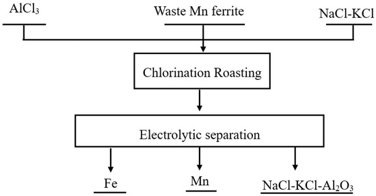
Ferrites are widely used in the electronics industry [1,2]. Since 2008, more than 250,000 tons of Mn-Zn ferrite have been produced annually in China [3]. A large amount of waste ferrite is generated in the manufacturing process of ferrite [3]. Traditional processes for treating waste ferrite included the following procedures: H2SO4 leaching, reducing, purification, co-precipitation, ball milling, sintering, etc. [4]. The reducing agent used in traditional processes is generally high-purity reduced iron powder [5]. The high price of high-purity iron powder severely affects the application of traditional processes [5]. The development of new processes is very necessary. Chlorination has received increasing attention in the treatment of solid waste and slag [6,7,8,9,10]. The crystal structure of Mn ferrite (MnFe2O4) is spinel [11]. In our previous work, we reported that molten salt chlorination destroyed the spinel structure of (Mn,Fe)(Cr,V)2O4 with AlCl3, and then MnCl2, CrCl3, FeCl2 and VCl3 were obtained [12,13]. In order to recover the Fe and Mn in waste ferrite, we propose that the new process includes the following two steps: chlorination of waste Mn ferrite with AlCl3 and the separation of Fe and Mn by molten salt electrolysis. Figure 1 shows a flow diagram of a novel method for the utilization of waste Mn ferrite.

Figure 1.
Flow diagram of a novel method for the utilization of waste Mn ferrite.
After chlorination, Fe and Mn in waste Mn ferrite were present in the form of FeCl3 and MnCl2. The electrodeposition of Mn2+ in a NaCl-KCl system was studied by Xiao et al. [14]. Ye et al. reported the formation of Mg-Li-Mn alloys from MnCl2-MgCl2-LiCl-KCl salt [15]. Fe2O3 was chlorinated by AlCl3, and then metallic Fe was obtained from molten salt containing FeCl3 by molten salt electrolysis [16]. However, the electrolysis and separation of FeCl3-MnCl2-NaCl-KCl systems has been not reported. In this work, as part of the foundational research on the recovery and separation of Fe and Mn from waste ferrite by a chlorination–electrolysis method, the electrolytic separation of Fe and Mn from FeCl3-MnCl2-NaCl-KCl molten salt has been studied.
2. Materials and Methods
Analytically pure NaCl, KCl, FeCl3 and MnCl2 are used in molten salt electrolysis. Equal molar NaCl and KCl were selected as the molten salt medium. The sample with MnCl2 (1.06 wt%)-FeCl3 (2.69 wt%)-NaCl-KCl was put in a high-temperature furnace, and heated to 800 °C under the protection of high-purity Ar gas. The electrolysis of Fe and Mn was conducted in a two-electrode cell. A tungsten wire and a graphite rode were used as the cathode material and anode material, respectively. After the electrolysis, the production of cathode surface was washed with deionized water to remove salt (NaCl, KCl, FeCl3, and MnCl2) from the molten salt medium. The morphology of production was analyzed with a scanning electron microscope (SEM, Zeiss Ultra 55, Oberkochen, Germany). X-ray diffraction (XRD, Rigaku Smartlab, Tokyo, Japan) with a Cu Kα radiation source was used to identify the phase of the electrodeposited products. To accurately determine the content of Fe and Mn in the products, the products were dissolved with aqua regia. Then the contents of Fe and Mn in solution were measured by inductively couple plasma optical emission spectroscopy (ICP-OES, Optima 5300DV, Waltham, MA, USA).
3. Results and Discussion
The electrolysis of molten salt (MnCl2 (1.06 wt%)-FeCl3 (2.69 wt%)-NaCl-KCl) was performed at 800 °C. The decomposition voltages of FeCl3 and MnCl2 are calculated by the following Equations (1)–(4):
where and are the decomposition voltage of MnCl2 and FeCl3, respectively. and are the theoretical decomposition voltage of MnCl2 and FeCl3, respectively. R is the ideal gas constant. T is the temperature in K. n is the number of electrons transferred. F is the Faraday constant. and are the activity of MnCl2 and the activity of FeCl3, respectively. and are the activity of Fe and the activity of Mn, respectively. is the activity of Cl2.
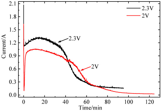
The activity of Cl2 is assumed to be 1 due to the high-purity Ar gas atmosphere in this experiment. The activity of both metallic Fe and metallic Mn are assumed to be 1. The concentrations of FeCl3 and MnCl2 are used to calculate the decomposition voltages instead of activity, which are attributed to low concentrations of FeCl3 and MnCl2 in MnCl2 (1.06 wt%)-FeCl3 (2.69 wt%)-NaCl-KCl molten salt. The theoretical decomposition voltages of MnCl2 and FeCl3 at 800 °C are calculated by the Factsage 6.4 program. The theoretical decomposition voltages of MnCl2 and FeCl3 at 800 °C are 1.8 V and 0.8 V, respectively. The decomposition voltages of FeCl3 and MnCl2 are calculated by Equations (2) and (4). Thus, the decomposition voltages of MnCl2 and FeCl3 at 800 °C are 2.3 V and 1.1 V, respectively. Considering the concentration polarization and electro-chemical polarization, the electrolysis voltages of 2.0 V and 2.3 V are selected. The effect of electrolysis time at different voltages and 800 °C on current is shown in Figure 2. The current vs. time curve shows a similar shape. With a constant voltage of 2.0 V applied, the current dropped quickly from 1.60 A to 0.09 A in seconds, which indicated that the cell voltage achieved equilibrium. As the electrolysis time increased to 8 min, the current gradually increased from 0.09 A to 1.04A. During this electrolysis, metal Fe is deposited on the W cathode, and the surface area of the W cathode increases. As the electrolysis time increases to 85 min, the current decreases to 0.09 A, which can be attributed to a decreased concentration of Fe3+. Finally, the current drops to about 0.02 A within 85–125 min [17]. With a constant voltage of 2.3 V applied, the current dropped quickly from 2.05 A to 1.11 A in seconds. This may correspond to the electrolytic cell of molten salt achieving equilibrium. As the electrolysis time increased to 13 min, the current gradually increased from 1.11 A to 1.30 A. During this electrolysis, metal Fe and Mn are deposited on the W cathode, and the surface area of the W cathode increases. As the electrolysis time increases to 60 min, the current decreases to 0.27 A, which can be attributed to a decreased concentration of Fe3+. Finally, the current drops to about 0.16 A within 60–95 min.

Figure 2.
The current–time curve of electrolysis of molten salt (MnCl2 (1.06 wt%)-FeCl3 (2.69 wt%)-NaCl-KCl, 800 °C).
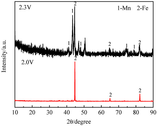
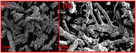
According to the calculated decomposition voltage, metal Fe was obtained when the electrolysis voltage exceeded 1.1 V. Meanwhile, metal Mn was obtained at voltages exceeding 2.3 V. The XRD in Figure 3 shows that the deposited products at 2.3 V are metal Fe and Mn. Meanwhile, the deposited product at 2.0 V is metal Fe. The electrolysis voltage is increased from 2.0 V to 2.3 V, and Mn2+ ions were electrolyzed to metal Mn. The SEM morphology of the deposited products is shown in Figure 4. The morphology of the product obtained at 2.0 V is dendritic. The morphology of metal Fe and Mn at 2.3 V exhibits a stick-like shape. The element contents of Fe and Mn in electrodeposited product were determined using ICP-OES. The Fe/Mn mass ratios of deposited product at 2 V and 2.3 V are 687 and 3.2, respectively. Thus, the different proportions of metal Fe-Mn were prepared by controlling the electrolytic voltages.

Figure 3.
The XRD analysis of the electrodeposited products by electrolysis with different constant cell voltages (MnCl2 (1.06 wt%)-FeCl3 (2.69 wt%)-NaCl-KCl, 800 °C).

Figure 4.
SEM analysis of electrodeposited products under different electrolysis voltages: (a) 2.0 V; (b) 2.3 V.
The economics of this process based on the production of 1 kg iron is discussed. Energy consumption and material costs were calculated as follows.
The conditions for the controlled preparation of different proportions of metal Fe-Mn by molten salt electrolysis were 2.0 V at 800 °C for 125 min. The energy consumption (Q, J) was obtained through Equation (5) [18].
where C is the specific heat of the material, J/(kg °C).m is the mass of the material, kg. is the temperature difference, °C. K is the heat conductivity coefficient, W/(M2 °C). A is the superficial area of the reaction vessel, m2. T is the reaction time, h. is the reaction heat during the reaction process, J. is the heat absorbed during the reduction process, J. is the energy consumption during the electro deposition, J.
Postulated conditions: the relationship of the specific heat of H2O (CH), NaCl (CNaCl) and KCl (CKCl) is described by Equation (6).
where CH, CNaCl, and CKCl are the specific heat of H2O, NaCl, and KCl, respectively.
CH = 4CNaCl = 4CKCl = 4.2 × 10³ J/(kg °C).
According to the Equations (5) and (6), the Equation (7) can be obtained.
where Q is the energy consumption in this process, J. K is the heat conductivity coefficient, W/(M2 °C). A is the superficial area of the reaction vessel, m2. is the reaction heat during the reaction process, J. is the heat absorbed during the reduction process, J.
One kilogram of standard coal produces 2.92 × 10⁷ J. Thus, about 4.8 kg standard coal (about 5.2 kg anthracite) was needed. Meanwhile, the price of anthracite is about RMB 900 per ton according to http://www.mycoal.cn. The price of energy consumption for producing 1 kg Fe is about RBM 4.7.
Molten salt electrolysis in this paper needs NaCl and KCl. The mass and the cost of materials required to produce 1 kg Fe is summarized in Table 1. The prices of the materials originate from https://www.yhs518.com/archives/2956.html. The cost of materials required to produce 1 kg Fe is about RMB 187. The price of 1 kg Fe and 0.5 kg Mn shown in Table 2 is RMB 9 according to https://www.mysteel.com/.

Table 1.
The cost of materials required to produce 1 kg Fe.

Table 2.
The price of products.
Although the cost of producing 1 kg Fe is about RMB 191.7, NaCl and KCl can be reused. No other impurities are introduced during molten salt electrolysis. When the molten salt ratio is MnCl2 (1.06 wt%)-FeCl3 (2.69 wt%)-NaCl-KCl for electrolysis, NaCl and KCl molten salt can be recycled 22 times to achieve profitability. In fact, the number of cycles of molten salt can be far more than 22 times. At the same time, the content of MnCl2 and FeCl3 in the molten salt is relatively low. When the content of MnCl2 and FeCl3 increases, profits can also be realized. Thus, this process is very industrially promising.
4. Conclusions
In summary, the separation of Fe and Mn from waste Mn ferrite by molten salt electrolysis was investigated. The electrolysis of molten salt (MnCl2 (1.06 wt%)-FeCl3 (2.69 wt%)-NaCl-KCl) was performed at 800 °C. The phase of product at 2.0 V is metal Fe, while metal Fe and Mn are obtained by molten salt electrolysis at 2.3 V. The Fe/Mn mass ratio of deposited products at 2.0 V and 2.3 V are 687 and 3.2, respectively. Direct extraction of Fe and Mn from waste Mn ferrite was achieved by a chlorination–electrolysis process. This process is simple and effective for the usage of waste Mn ferrite. The chlorination mechanism for waste Mn ferrite and the electrolysis mechanism for FeCl3-MnCl2 are the subject of further research.
Author Contributions
Conceptualization, S.L. and L.W.; methodology, S.L.; validation, S.L.; formal analysis, S.L.; investigation, S.L.; resources, S.L.; writing—original draft preparation, S.L.; writing—review and editing, L.W.; visualization, S.L.; supervision, L.W.; funding acquisition, S.L. and L.W. All authors have read and agreed to the published version of the manuscript.
Funding
This research was funded by National Natural Science Foundation of China (No. 51904286, 51922003, 51774027, 51734002) and China Postdoctoral Science Foundation (2019M650848).
Acknowledgments
The authors are grateful for the financial support of this work from the National Natural Science Foundation of China (No. 51904286, 51922003, 51774027, 51734002), and China Postdoctoral Science Foundation (2019M650848).
Conflicts of Interest
The authors declare no conflict of interest.
References
- Liu, S.Y.; Li, S.; Wu, S.; Wang, L.J.; Chou, K.C. A Novel Method for Vanadium Slag Comprehensive Utilization to Synthesize Zn-Mn Ferrite and Fe-V-Cr Alloy. J. Hazard. Mater. 2018, 354, 99–106. [Google Scholar] [CrossRef] [PubMed]
- Bollero, A.; Rial, J.; Villanueva, M.; Golasinski, K.M.; Seoane, A.; Almunia, J.; Altimira, R. Recycling of Strontium Ferrite Waste in a Permanent Magnet Manufacturing Plant. ACS Sustain. Chem. Eng. 2017, 5, 3243–3249. [Google Scholar] [CrossRef]
- Li, K.K.; Peng, C.H.; Jiang, K.Q. The Recycling of Mn–Zn Ferrite Wastes Through a Hydrometallurgical Route. J. Hazard. Mater. 2011, 194, 79–84. [Google Scholar] [CrossRef] [PubMed]
- Bai, B.S. The Study on the Recycling of Waste MnZn Ferrite by Hydrometallurgy-method. Master’s Thesis, Central South University, Hunan, China, 2007. [Google Scholar]
- Zhu, Y. Study on the Preparation of High Peameability Ferrite Used for Anti-electro-magnetic-interference from MnZn Soft Ferrite Wastes. Master’s Thesis, Central South University, Hunan, China, 2011. [Google Scholar]
- Du, G.C.; Fan, C.L.; Yang, H.T.; Zhu, Q.S. Selective Extraction of Vanadium from Pre-oxidized Vanadium Slag by Carbochlorination in Fluidized Bed Reactor. J. Clean. Prod. 2019, 237, 117765. [Google Scholar] [CrossRef]
- Liu, S.Y.; Wang, L.J.; Chou, K.C. Selective Chlorinated Extraction of Iron and Manganese from Vanadium Slag and Their Application to Hydrothermal Synthesis of MnFe2O4. ACS Sustain. Chem. Eng. 2017, 5, 10588–10596. [Google Scholar] [CrossRef]
- Ma, E.; Lu, R.X.; Xu, Z.M. An efficient rough vacuum chlorinated separation method for the recovery of indium from waste liquid crystal display panels. Green Chem 2012, 14, 3395–3401. [Google Scholar] [CrossRef]
- Carbral-Pinto, M.M.S.; Inácio, M.; Neves, O.; Almeida, A.A.; Pinto, E.; Oliveiros, B.; Silva, E.A.F.D. Human Health Risk Assessment Due to Agricultural Activities and Crop Consumption in the Surroundings of an Industrial Area. Expos. Health 2020, 12, 629–640. [Google Scholar] [CrossRef]
- Carbral-Pinto, M.M.S.; Marinho-Reis, P.; Almeida, A.; Pinto, E.; Neves, O.; Inácio, M.; Gerardo, B.; Freitas, S.; Simões, M.R.; Dinis, P.A.; et al. Links between Cognitive Status and Trace Element Levels in Hair for an Environmentally Exposed Population: A Case Study in the Surroundings of the Estarreja Industrial Area. Int. J. Environ. Res. Public Health 2019, 16, 4560. [Google Scholar] [CrossRef] [PubMed]
- Liu, S.Y.; Wang, L.J.; Chou, K.C. Synthesis of Metal-Doped Mn-Zn Ferrite from the Leaching Solutions of Vanadium Slag Using Hydrothermal Method. J. Magn. Magn. Mater. 2018, 449, 49–54. [Google Scholar] [CrossRef]
- Liu, S.Y.; Wang, L.J.; Chou, K.C. A Novel Process for Simultaneous Extraction of Iron, Vanadium, Manganese, Chromium, and Titanium from Vanadium Slag by Molten Salt Electrolysis. Ind. Eng. Chem. Res. 2016, 55, 12962–12969. [Google Scholar] [CrossRef]
- Liu, S.Y.; Wang, L.J.; Chou, K.C.; Kumar, R.V. Electrolytic Preparation and Characterization of VCr Alloys in Molten Salt from Vanadium Slag. J. Alloy. Comp. 2019, 803, 875–881. [Google Scholar] [CrossRef]
- Xiao, S.J.; Liu, W.; Gao, L. Cathodic Process of Manganese (II) in NaCl-KCl Melt. Ionics 2016, 22, 2387–2390. [Google Scholar] [CrossRef]
- Ye, K.; Zhang, M.L.; Chen, Y.; Han, W.; Yan, Y.D.; Wei, S.Q.; Chen, L.J. Study on the Preparation of Mg–Li–Mn Alloys by Electrochemical Codeposition from LiCl–KCl–MgCl2–MnCl2 Molten Salt. J. Appl. Electrochem. 2010, 40, 1387–1393. [Google Scholar] [CrossRef]
- Haarberg, G.; Kvalheim, M.E.; Rolseth, S.; Murakami, T.; Pietrzyk, S.; Wang, S.L. Electrodeposition of Iron from Molten Mixed Chloride/Fluoride Electrolytes. ECS Trans. 2007, 3, 341–345. [Google Scholar] [CrossRef]
- Zou, X.L.; Lu, X.G.; Li, C.H.; Zhou, Z.F. A Direct Electrochemical Route from Oxides to Ti-Si Intermetallics. Electrochim. Acta 2010, 55, 5173–5179. [Google Scholar] [CrossRef]
- Wang, H.G.; Zhang, M.; Guo, M. Utilization of Zn-Containing Electric Arc Furnace Dust for Multi-Metal Doped Ferrite with Enhanced Magnetic Property: From Hazardous Solid Waste to Green Product. J. Hazard. Mater. 2017, 339, 248–255. [Google Scholar] [CrossRef] [PubMed]
Publisher’s Note: MDPI stays neutral with regard to jurisdictional claims in published maps and institutional affiliations. |
© 2020 by the authors. Licensee MDPI, Basel, Switzerland. This article is an open access article distributed under the terms and conditions of the Creative Commons Attribution (CC BY) license (http://creativecommons.org/licenses/by/4.0/).