Article

Methodology for Concurrent Multi-Parametric Physical Modeling of a Target Natural Unfractured Homogeneous Sandstone

1
State Key Laboratory of Petroleum Resources and Prospecting, China University of Petroleum (Beijing), Fuxue Rd., No. 18, Beijing 102249, China
2
Key Laboratory of Petroleum Engineering Ministry of Education, China University of Petroleum (Beijing), Fuxue Rd., No. 18, Beijing 102249, China
*
Author to whom correspondence should be addressed.
Processes 2020, 8(11), 1448; https://doi.org/10.3390/pr8111448
Submission received: 12 September 2020 / Revised: 2 November 2020 / Accepted: 9 November 2020 / Published: 12 November 2020
(This article belongs to the Section Chemical Processes and Systems)

Abstract

:
In petroleum, geological and environmental science, flow through porous media is conventionally studied complementarily with numerical modeling/simulation and experimental corefloods. Despite advances in numerical modeling/simulation, experimental corefloods with actual samples are still desired for higher-specificity testing or more complex mechanistic studies. In these applications, the lack of advances in physical modeling is very apparent with the available options mostly unchanged for decades (e.g., sandpacks of unconsolidated packing materials, industry-accepted substitutes with fixed/mismatching petrophysical properties such as Berea sandstone). Renewable synthetic porous media with adjustable parameters are the most promising but have not advanced adequately. To address this, a methodology of advanced physical modeling of the fundamental parameters of dominant mineralogy, particle size distribution, packing, and cementation of a target natural porous media is introduced. Based upon the tight physical modeling of these four fundamental parameters, the other derived parameters of interests including wettability, porosity, pore throat size distribution, permeability, and capillary pressure can be concurrently modeled very close as well by further fine-tuning one of the fundamental parameters while holding the rest constant. Through this process, concurrent multi-parametric physical modeling of the primary petrophysical parameters including particle size distribution, wettability, porosity, pore throat size distribution, permeability, capillary pressure behavior in a target sandstone becomes possible.

1. Introduction

As a complex material, geological porous media such as coal, aquifer, petroleum reservoir are important for human survival in application ranging from groundwater remediation [1,2], carbon storage [3,4], to petroleum exploitation [5]. To better exploit and manage these valuable resources, researchers need both numerical and physical simulation tools of sufficient sophistication. Numerical simulation tools have seen dramatical improvement with advances in computing power and software sophistication [6,7]. Advances in 2D microfluidic devices have enabled better understanding of the transport phenomenon at the microscale through addition of the visual component [8,9]. However, for the 3D physical modeling needed for more complex physical simulation, the advances has been stagnant. As of now, researchers need a tailorable, renewable substitute with stable properties (e.g., particle size distribution, pore-throat distribution, porosity, permeability, wettability, and capillary pressure behavior, etc.) that can be adjusted at will to match comparably well to the sedimentary rock of their interest for different testing/research purposes. However, these transport, storage, and physicochemical parameters of geological formations are extremely difficult to model in unison in one physical model. Due to these difficulties, researchers often just settled with whatever is available at cost or can best put together themselves. These compromised solutions ranged from the use of a well-known natural substitute such as Berea sandstone or Austin chalk [10,11], unconsolidated sandpacks of various packing materials [12], or synthetic porous material with often just the permeability and porosity matched to the target [13,14]. Even in the case when the actual reservoir rocks or outcrops are available, problems of insufficient quantity, heterogeneity [15], poor quality can still be a problem for researchers interested in doing parametric mechanistic studies or optimization testing. As the lack of availability of adequate substitute inevitably started to impact their research, faced with no other alternatives, researchers have attempted to make synthetic porous material in increasing sophistication [16,17,18,19]. Due to the complex and interrelated nature of the petrophysical parameters of these natural porous material imparted by the diagenetic and sedimentation process, these try-and-see attempts in making synthetic porous materials were mostly limited to varying certain synthesis parameters out of the context of the whole to see the effect on a single petrophysical parameter. Additionally, these attempts often are still dealing with common unresolved synthesis problems such as poor consolidation and instability for sand packs [20], artificial oil-wetness with use of organic binder such as epoxy resin which starts to soften at 60 °C, or unnatural fragility and high alkalinity from use of sodium silicate as binding agent [21], etc. To address these challenges, the authors introduce a method that can achieve concurrent physical modeling of the multiple petrophysical parameters of interests to researchers to a target formation. This is done by first identifying mineralogy, particle size distribution, packing, and cementation as the primary independent petrophysical variable and recognizing that physical modeling of all other dependent petrophysical parameters can be achieved simply through adjusting these four independent variables. Using three natural sandstone samples with permeability spanning the range of 88–1186×10−3 µm2 from a petroleum-bearing formation in Northeastern region of China as an example, this methodology was shown to be applicable to achieve successful concurrent multi-parametric physical modeling of the pore network-related petrophysical properties including porosity, permeability, wettability, pore throat size distribution, and capillary pressure behavior in one synthetic sandstone. For the first time, a theoretically-driven, experimentally-validated methodology to concurrently physically model multiple petrophysical parameters of interest to researchers in a target sandstone is reported.

The Theoretical Physical Pathway Governing Interactions of Pore-Network Related Physical Parameters in a Natural Sandstone

In synthesis of micro–meso-scale artificial porous materials, material parameters such as the particle size distribution, the pore size distribution and the surface area during the synthesis (e.g., colloidal metal catalytic nanoparticles) are mostly governed by reaction synthesis-related parameters such as temperature, reactant concentration, pH, etc. [22,23]. The ensemble of petrophysical properties unique for each natural porous media is also a function of its natural synthesis condition such as particle size distribution as a result of diagenesis, mineralogy of formation, packing induced by the weight of the overburden, and cementation introduced during the sedimentation process, etc. For the synthetic porous materials used in the manufacturing and chemical processing industry, the material parameters are all artificial in nature and of interests only when it can enhance throughput [24], thermal conductivity [25,26], reaction rate [27,28], etc. In contrast, as a tool for transport in porous media-related research, a naturally-porous material intrinsically comes with a set of very specific natural petrophysical attributes that the researchers want to get as close to as possible in their research physical models for increased data relevancy. To physically model a target porous media, the prevalent approach in the literature mostly consisted of a try-and-see type of effort. Ronan experimented with a novel calcite-in-situ cemented artificial core doped with radioactive agent and reported variable porosity and permeability as a function of carbonate-containing reactant solution flushes. Ronan reported by varying the particle size distribution through sieving of particles in the size range of 107–355 μm and varying the number of solution flushes, synthetic rocks of permeability range of 3000–30,000 × 10−3 μm2 and porosity of ~32% were achieved [13]. Al-Homadhi et al. experimented with compaction pressure of 78–162 MPa, particle size range of 45–300 μm, cementation of sodium silicate composition of 4–8%, curing temperature of 300 °C and reported achieving homogeneous cores with permeability range of 15–5000 × 10−3 μm2, porosity range of 20–33%, and pore size range of 11–50 μm [16]. Costa et al. experimented with sand with average size of 181 μm consolidated with sintered ceramic clay of 20–40% weight content, compression pressure range of 10–20 MPa, and sintering temperature range of 850–950 °C and reported achieving synthetic sandstone with a porosity of 51–62% and permeability of 2–21 × 10−3 μm2 [29].
These previous works were vital in pointing out the fundamental parameters that needed to be considered for the physical modeling of synthetic sandstone. However, this type of research share similarity in being limited in scope to just finding out the effect on a few isolated petrophysical parameters out of the context of the whole through varying one or more of the synthesis condition. None of these previous works have attempted to actually physically model the entire ensemble of the petrophysical properties together for a target natural lithological formation as a whole due to the challenge involved, both theoretically and methodologically. Theoretically, existing research has yet to clearly work out the physical interaction pathway governing how the relevant physical parameters are layered hierarchically and interrelated. Methodologically, if the goal is to synthesize a physical model with the majority of the physical parameters made comparable to those of natural rock, there are many synthesis-related problems and decisions that need to be confronted and resolved. These issues range from sourcing the required minerals of sufficient purity, selection of a binding material that does not impart a diverging wettability or surface chemical properties, addition of clay, to modeling dissolution porosity, with each problem and decision poses a significant challenge.
In this work, in tackling the theoretical problem of how to link these assortments of physical parameters together into a coherent whole, the authors looked for the answer through close examination of a thin section such as the one shown in Figure 1a made of a relatively homogeneous natural sandstone and identifying the fundamental physical parameters therein [30]. To the knowing eye, careful examination of the thin section identified mineralogy, particle size distribution (PSD), packing, and level of cementation as the four fundamental parameters governing the petrophysical behavior of sedimentary rock. Thus, petrophysical modeling of a porous media can be thought of in terms of the following Equation (1).
f(x) = f(mineralogy, PSD, packing, cementation).
In Equation (1), the mineralogy imparts the rock its surface-chemical affinities that govern its wettability and surface chemical behavior with fluids; The particle size distribution (PSD) can be seen as the bone matrix of the rock whose remaining void creates the basic framework and upper limit on porosity; The packing can be seen as how loosely or snugly the particle grains in the bone matrix are brought into contact with each other and set into each other which is mainly a function of pressure; The cementation level can be seen as the extent of the fillings of the inter-particular void that sets the lower limit on porosity. Following this logic, the physical modeling of the pore network of a homogeneous unfractured sandstone depicted as the left-over void in Figure 1d can be reduced to the results of superposition of the particle size distribution at packing pressure and the matching mineralogy represented in Figure 1b with the cementation shown in Figure 1c. In another word, once the four independent synthesis conditions of a synthetic sandstone are matched very closely to that of the target sandstone, then the match of the pore network which is the void left out of the sum of the superposition of these four components together should, in theory, be very close as a result. If the close physical modeling of the pore network to the target in the synthetic sandstone is achieved, then the pore network-derived petrophysical properties such as the porosity, the pore throat size distribution, the permeability, and the capillary pressure behavior should get very close to the target as well.
With the four fundamental rock properties identified, the order of the rest of the dependent physical properties (i.e., wettability, capillary pressure behavior, permeability, pore-throat distribution, and porosity, etc.) can be deduced. The physical pathway of how these parameters are interrelated are shown tentatively in Figure 2. Wettability, being a property that is a synergistic result of the interaction of the fluids and the mineralogy of the rock, and not of a pure rock property is shown in dashed line. According to the physical pathway outlined in Figure 2, the hypothesis in this paper is that if the fundamental attributes of the particle size distribution, cementation, packing, and mineralogy are physically modeled very closely to a natural target homogeneous unfractured lithology in a synthetic sandstone, then the rest of the dependent petrophysical parameters in Figure 2 should become very near to that of the target rock as well. This is attributed to the decreasing order of freedom allowed for the dependent petrophysical parameters to vary as an increasing number of independent fundamental parameters acting as constraints becomes fixed (i.e., if particle size distribution and the packing in the synthetic sandstone is matched very exactly to the target, then porosity, the pore throat size distribution, and the permeability become simply dependent only on the cementation level).

2. Materials and Methods

2.1. Methodology

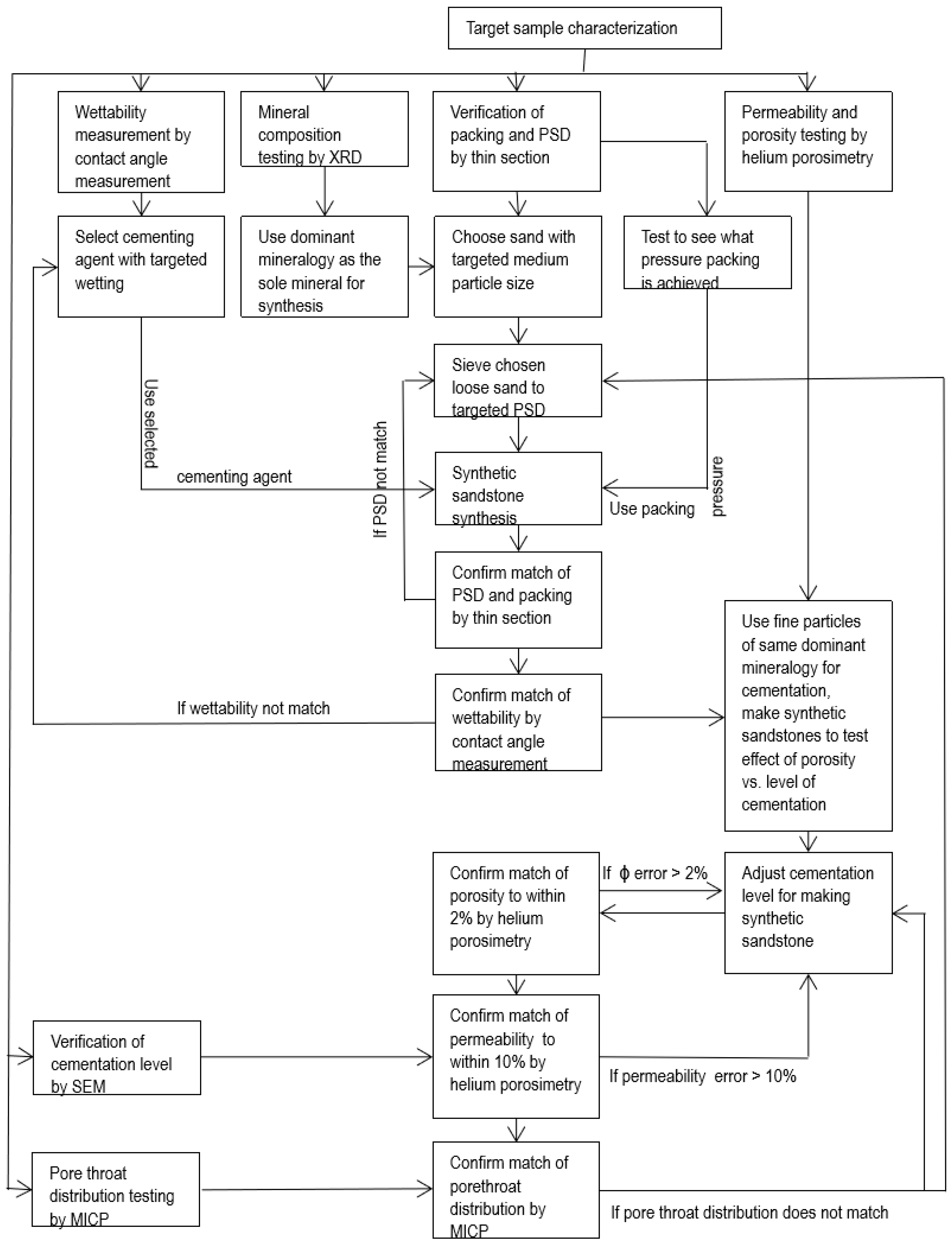
Once the theoretical physical pathways governing how the ensemble of petrophysical parameters are interrelated shown in Figure 2 are deduced, the methodology to achieve multi-parametric physical modeling of a homogeneous unfractured sandstone can be inferred from it with the physical modeling of each parameters sequentially built up according to how they are layered and interrelated hierarchically in it. Such a methodological flow chart is shown in Figure 3.
The application of this methodology started with full characterization of a target sample with wettability measurement by contact angle measurement, mineral composition testing by X-ray diffraction (XRD), PSD testing by thin section, permeability and porosity testing by helium porosimetry, pore throat size distribution testing by mercury injection capillary pressure testing (MICP), and observation of cementation level by scanning electron microscopy (SEM). Based upon the mineralogy testing, loose sand that matched the dominant mineralogy was chosen. A cementing agent that can impart comparable wetting state in the synthetic sandstone to the target was chosen. With the PSD available, the medium particle size of the target sample was used to select the mesh size of the loose sand to be used. Using the thin section as a guide, the chosen loose sand was sieved and tested repeatedly until the PSD in the loose state matched to that of the target by laser particle size diffraction analysis. The preliminary synthetic sandstones tries were made and its wettability was tested by contact angle measurement to see if it’s comparable to that of the target. If not, the chemistries of the cementing agent were adjusted. The particle size distributions of the synthetic samples were tested against that of the target by thin section analysis to see if they match. If the match was off, a slight adjustment of the particle size distribution by sieving was done and the process repeated. A set of synthetic sandstones at different packing pressures were made to find the setting pressure. The porosity and permeability testing by helium porosimetry for the synthetic sandstone samples as a function of varying packing pressure was performed to find the packing pressure at which the sand particles can set. The equilibrated packing pressure was assumed to be the pressure above which porosity difference changed by less than 1% signifying grain particles has reached equilibrated packing. With the packing pressure, dominant mineralogy, cementing agent, and PSD matched or selected, the synthetic sandstones tries were made with varying degree of cementation level (using 2000 mesh quartz fines and the corresponding amount of gel) until the error of its measured porosity to the target fell below 2%. Once this was achieved, the sample permeability was tested next. If the sample permeability did not get within 10% error of the target, then further fine adjustment of the cementation level was made, and the synthesis repeated again until this was achieved. Once the permeability of the synthetic sample fell lower than 10% of the target, then part of its sample was sent for mercury injection capillary pressure testing to see if the capillary pressure behavior and the pore throat size distribution match well to that of the target. If not, then more fine adjustment was made to the cementation level or the particle size distribution until they match.

2.2. Materials

Three representative sandstone samples 9-1, 7-9, and 13-5 from an oilfield in Heilongjiang Province, China were used as the target lithology for the purpose of this study. Pure quartz particles were purchased from Lingshou County Zhenxing Mineral Processing Plant, Hebei Province, China and tested to be 99% purity by XRD. For this work, 60–100# and 80–120# (note: # stands for mesh size) quartz sand with the corresponding particle size range of 149–250 and 125–177 μm respectively were chosen for synthetic sandstone synthesis because they encompass the medium particle size of the target samples. Fine 2000# quartz sand with 6 μm average diameter particle size was chosen to be used as the filler due to its small size. A proprietary inorganic binder was synthesized with reagent-grade ingredients purchased from West Long Chemical Reagent Company to be used as the cementing agent.

2.3. Equipment

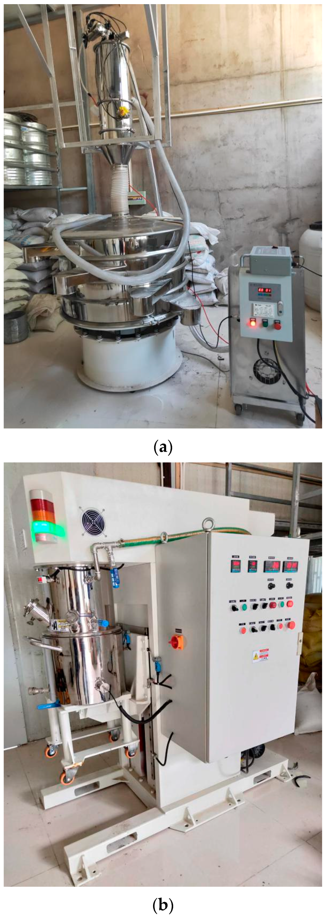
In the making of the synthetic sandstone, the following equipment shown in Figure 4 were used: a mechanical sieve by Qetesh, Shanghai, China, a 20 L mechanical mixer by Qetesh, Shanghai, China, a 500-ton industrial hydraulic press with custom mould by Jier, Jinan, China, a coring drill press, and a table saw from ZHBW, Qingdao, China.

2.4. Synthetic Sandstone Synthesis

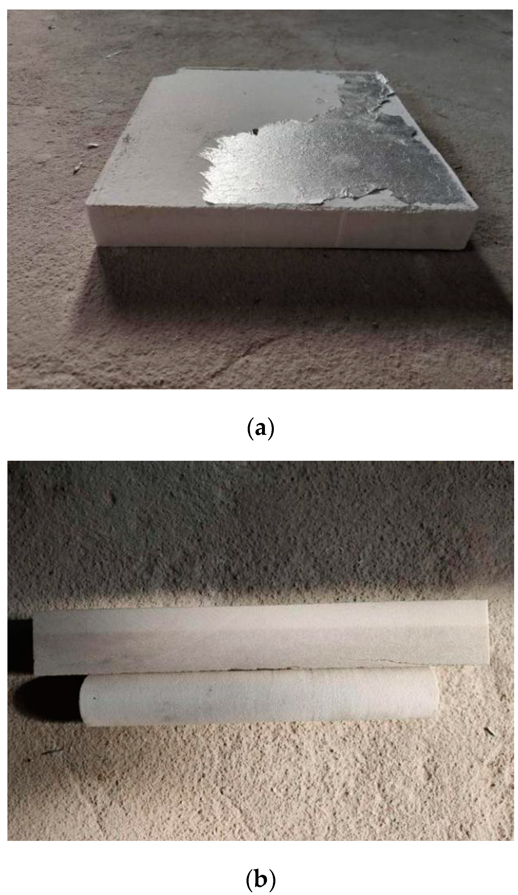
Making of the synthetic sandstone starts with the best candidate of sieved sand. The sieve sand was sieved according to the methods detailed above to match the particle size distribution of the target using the mechanical sieve in Figure 4a. The sieved sand with the desired particle size distribution was combined with a certain ratio of 2000# sand used as a filler to add up to 25 kg total for each synthesis. A corresponding amount of the proprietary binding agent was prepared and mixed in with the sands and put inside the 20 L mechanical mixer shown in Figure 4b. Once the sand-binder mixture was well-mixed, the sand mixture was scooped out and put inside a 30 cm × 30 cm × 10 cm sand mould and compressed to a hard cake under the hydraulic press shown in Figure 4c at the set pressure. Afterwards, the pressed sand cake was put inside a constant temperature oven and cured at 160 °C for 5 h to set the inorganic binder. After the curing, the appearance of the final synthetic sandstone is shown in Figure 5a with cored and blocked section shown in Figure 5b.

3. Results

3.1. Target Sample Characterization

Three target natural sandstone samples of 9-1, 13-5, and 7-9 with permeability range of 88–1186 × 10−3 µm2 were sent for helium porosimetry testing of porosity and permeability, pore throat size distribution testing by mercury injection capillary pressure (MICP), particle size distribution analysis by thin section, and micro-scale examination of the level of cementation by scanning electron microscopy (SEM) to be used as target guidelines for synthetic sandstone. The results of the test of these natural sandstones and their corresponding synthetic counterparts are shown in the corresponding sections below.

3.2. Match of the Mineral Composition

The results of the X ray-diffraction compositional analysis is shown in Table 1. It can be seen that the mineral composition of the samples is quartz-dominated with a range of 51–55%. The second most abundant mineral component is the feldspars with a range of 32–39%. Dolomite/calcite/rock salt can be seen as impurities with range of less than 3%. Clay made up the rest of the mineral composition at range of 6–12%. Due to the difficulties of locating supplies of feldspar at sufficient purity, quartz was used as a mineral substitute for feldspar. This decision was justified as the two are similarly water-wet with contact angles at 24–40° and with similar hardness at 6–7 on the Mohs scale [31,32]. The small amounts of calcite, dolomite, and rock salt were also replaced by quartz for simplicity as their compositional ratios were not very significant. The presence of clay (i.e., the montmorillionites and kaolinites) is known for causing swelling and fine migration upon contact with water which can result in formation damage [33,34]. For the stability of synthetic sandstone better-suited for testing/research purposes, the clays were excluded in the synthesis of the synthetic sandstone in this study. For the reasons listed above, the synthetic sandstone was made in entirety with quartz bonded together with inorganic cementing agent. Since the three samples have >87% quartz and feldspar, this decision was justified for the similarities between the two primary mineral components and out of concern for the stability of the synthetic product.

3.3. The Matching of the Particle Size Distribution

3.3.1. The Loose sand Selection

From the thin section analysis, the medium particle sizes of the target samples were determined for target samples 9-1, 7-9, and 13-5 as 177, 125, and 125 μm respectively. Based upon the test results, the best match of available loose sands for samples 9-1, 7-9, and 13-5 were 60–100#, 80–120#, 80–120# respectively with 60–100# having a particle size range of 149–250 μm, while 80–120# having a particle size range of 125–177 μm.

3.3.2. The Trimming of the Loose Sand to Match the Particle Size Distribution of Target Prior to Synthetic Sandstone Synthesis

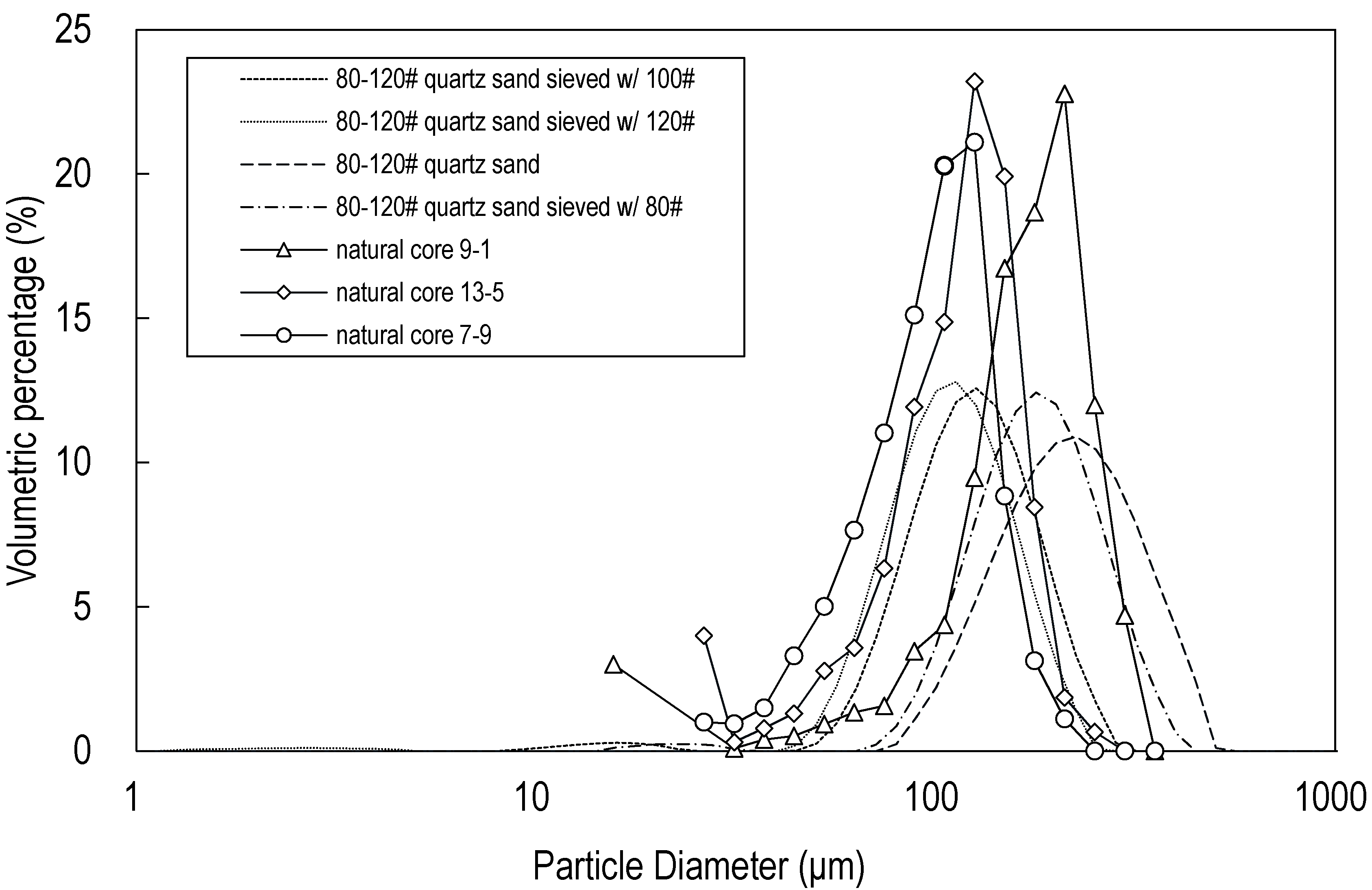
Figure 6 shows the particle size distribution results by laser diffraction particle size distribution testing of the 80–120# sand sieved at different mesh size in comparison to the target samples 9-1, 13-5 and 7-9. The progression from right to left of dash to dotted line indicates the sieving results of progressively smaller sieve size (bigger mesh size number). For target sample 7-9, 80–120# sand sieved with 100 mesh sieve (second dotted curve from the left) was selected to make the corresponding synthetic sandstone. For target 13-5, 80–120# sand sieved with 80 mesh sieve (second dash-dotted curve from the right) was selected to make the corresponding synthetic sandstone. Similar results for 60–100# sand is not shown. For target sample 9-1, the best fit was the 60–100# sand sieved with 60 mesh sieve. With the loose sand sieved to match the particle size distribution of the target prior to synthetic sandstone synthesis, the next step is to make a synthetic rock and confirm the particle size distribution in-situ with a sample sent for thin section analysis.

3.3.3. Match of Particle Size Distribution to Targets in Synthetic Sandstone by Thin Section Analysis

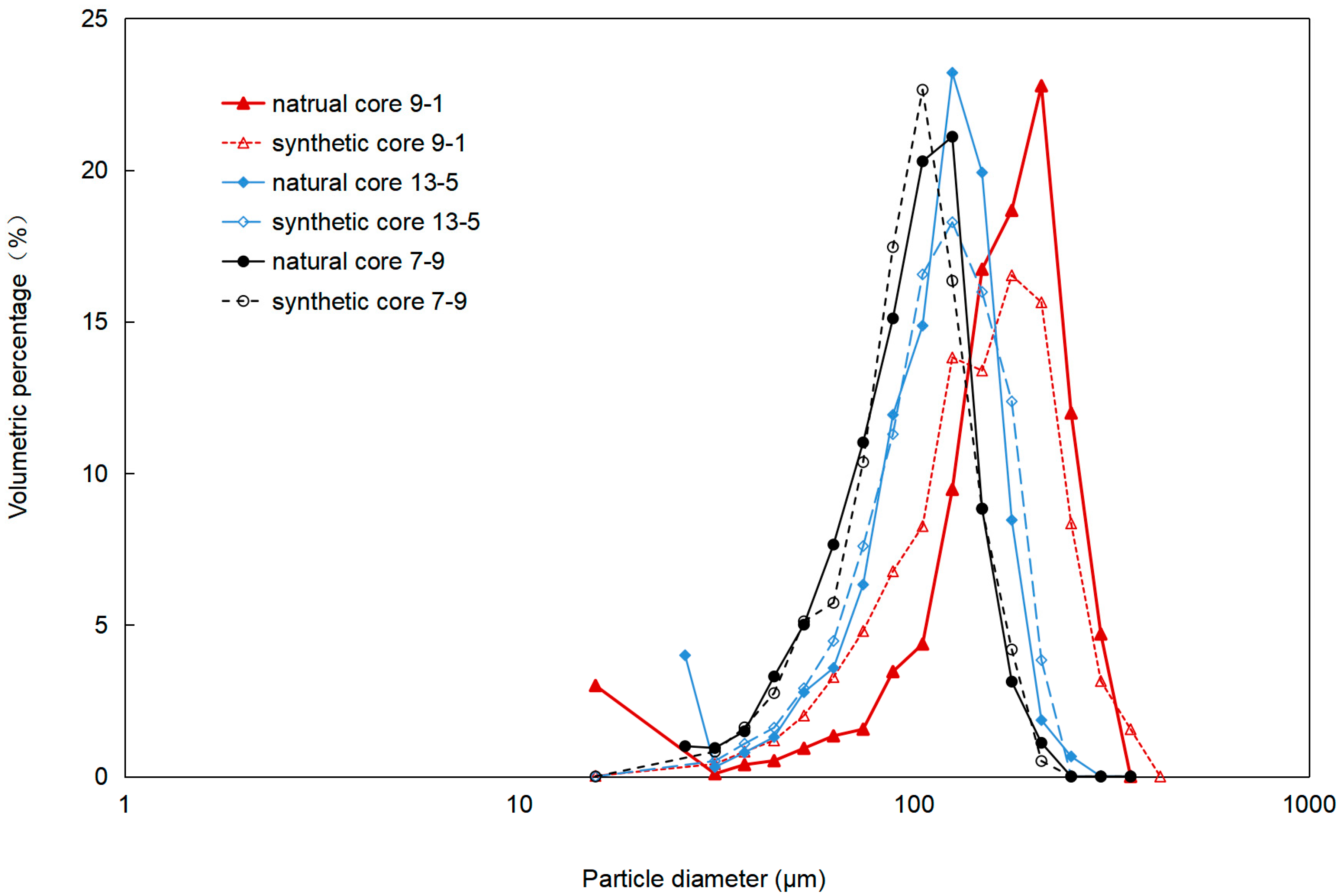
For verification of the particle size distribution in-situ, cored samples from the synthetic sandstone made with the sieved loose sands match to that of the target were then sent for thin section analysis. Once the match of the particle size distribution of the target was confirmed by thin section analysis as shown in Figure 7, with span error of less than 0.3, Equation (2), then the particle size distribution modeling step was considered complete.
span   error   =   span   of   target     span   of   synthetic   sandstone span   of   target
span   = d 0.9 d 0.1 d 0.5
With d0.9 as the diameters at which 90% of particles fall below this value; d0.1 as the diameters with which 10% of particles falls below this value; and d0.5 as the diameters with which 50% of particles falls below this value. Using this method, the span errors for 9-1, 13-5, and 7-9 were determined to be 0.27, 0.16, and 0.05 respectively.

3.4. The Match of Wettability

As a result of the choice of simplified mineral composition, the wettability of the synthetic sandstone differed slightly from the target. The results of the contact angle testing of the target samples and the synthetic samples made with deionized water at standard conditions were 27.5–42.5° and 21–33° respectively, with the midrange error of contact angle of 23% calculated by Equation (4). Both the target sandstones and the synthetic samples were shown to be relatively water-wet.
Midrange   error = M i d r a n g e t arg e t M i d r a n g e s y n t h e t i c _ s a n d s t o n e M i d r a n g e t arg e t  
Midrange = maximum   contact   angle + minimum   contact   angle 2   .
Figure 8 shows the pictures of the contact angle measurements of the target (a–c) and synthetic samples (d–f). The results show that the use of the quartz sand and the selected cementing agent gave comparable wettability by contact angle measurement to the target. Since the mineral composition affects primarily the mechanical properties of the rock and its wettability, the comparable match of the wettability of the synthetic sandstone gives additional support for the use of pure quartz for modeling the mineral composition of quartz-and-feldpar-dominated sandstone.

3.5. Match of Packing

The results of the experiments to match packing as a function of the increasing compaction pressure is shown in Figure 9 where the porosity and the permeability of synthetic sandstone as a function of the pressure is shown. The left-side y-axis shows permeability while the right-side y-axis shows porosity, and the x-axis plots the pressure of compression. Results show that the reduction in porosity levels off to less than 1% at the pressure range of 30–40 MPa while the permeability keeps decreasing. The leveling of porosity at the compaction pressure of 30 MPa suggested that at this pressure, it was sufficient to bring the sands fully in contact with each other to induce consolidated packing. Therefore, 30 MPa was taken to be the pressure to be used as the packing pressure.

3.6. The Match of Porosity: Rough Adjustment Phase of Cementation Level

Using the packing pressure set at 30 Mpa, synthetic sandstone tries were made with an increasing amount of 2000# sand as the fillers in increments of 5–10% ratio increase for the rough adjustment phase of cementation in order to quickly zero in on the vicinity of the appropriate cementation level to achieve close porosity modeling. The porosity of each try was tested in comparison to the target. Figure 10 shows the porosity of the synthetic sandstone tries vs. 2000# sand ratio used as the filler (The notation ss in Figure 10 labels in the legend denotes synthetic sandstone). The dashed horizontal lines are the target porosities of the three target samples. Once the porosity comes within 2% of the target, then the sample was considered ready for the fine-tuning of its cementation level for the approximation of the permeability and the pore throat size distribution modeling in the next step.

3.7. The Match of Permeability: Fine Adjustment Phase of Cementation Level

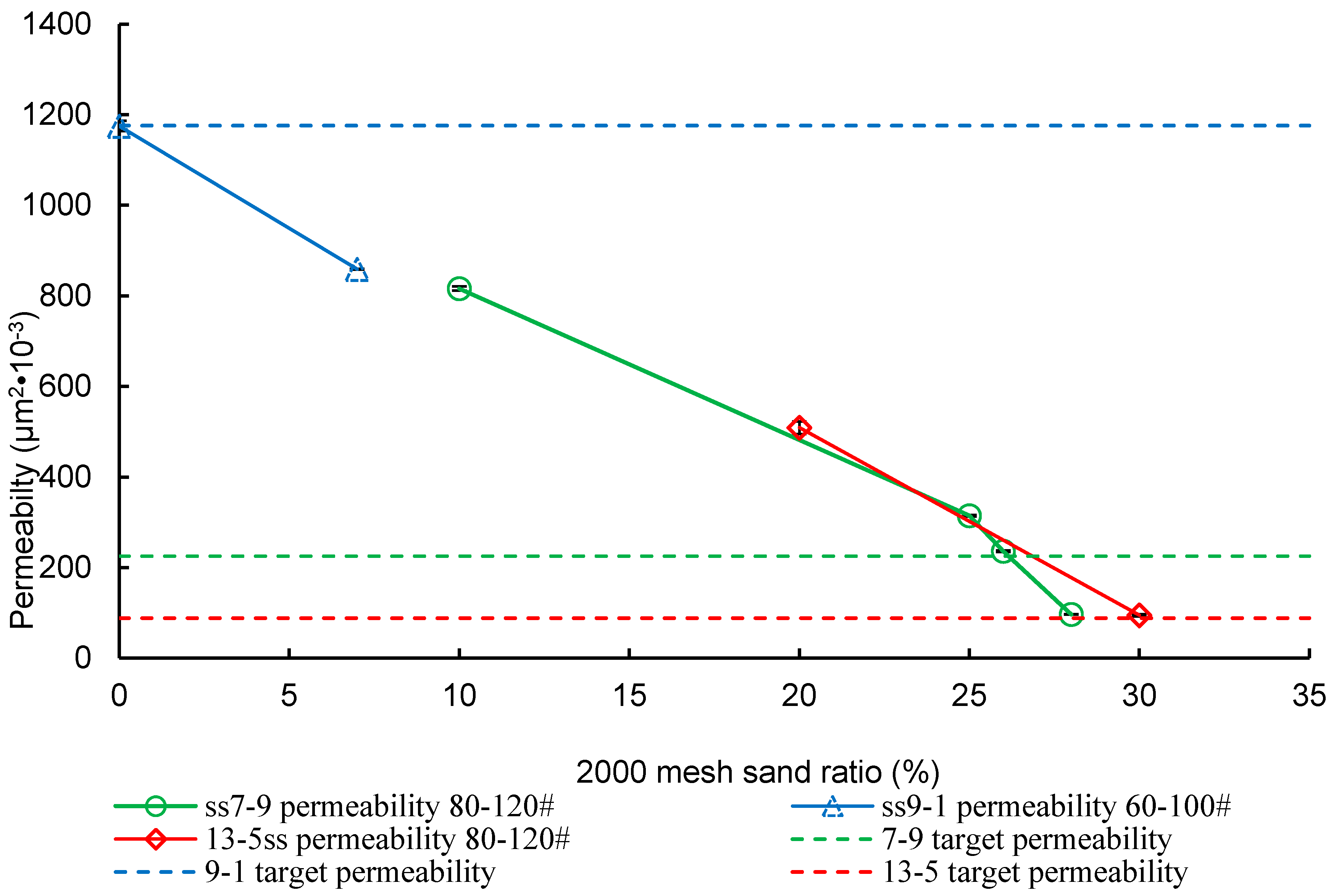
At the end of the rough adjustment phase of the cementation level, the sample with porosity within 2% error of the target was also tested for permeability by helium porosimetry to see if the permeability will also come within 10% error of the target. If not, the synthetic sandstone tries were repeated by varying the amount of 2000# sands much more minutely (in 1–2% ratio jumps) with the corresponding amount of binder until the tested gas permeability came within ~10% error respectively from the target as shown in Figure 11.

3.8. The Match of the Pore Throat Size Distribution: Fine Adjustment of Cementation Level and PSD

Once the error of permeability modeling of a synthetic sandstone tries decreased beneath 10% to that of the target, it was then sent for pore-throat distribution analysis by MICP [35,36]. If the pore throat size distribution of the synthetic sandstone tries did not match well to that of the target, then a further slight adjustment to the filler ratio (fine sands along with the corresponding amount of binder) was made again to attempt to achieve a better fit of the pore throat size distribution to the target. Figure 12a illustrates adjustment of the capillary pressure through increasing the ratio of fine sand used for cementation level adjustment. In Figure 12a, the arrow points toward the direction of increasing fine sand ratio (0%, 4%, to 6.67 wt%), with a resultant corresponding change to the entry pressure of the capillary pressure curve. Figure 12b shows the same for more minute amount of increment in fine sand ratio with an increment of 0.33%, 0.66%, to 1.00 wt%. Figure 12c,d show the pore throat size distributions also shift to the left (i.e., pore-throats are getting smaller) with an increasing fine sand ratio. If at this point, the pore throat size distribution match is still very far off after significant adjustment, then a slight adjustment to the PSD may be necessary.
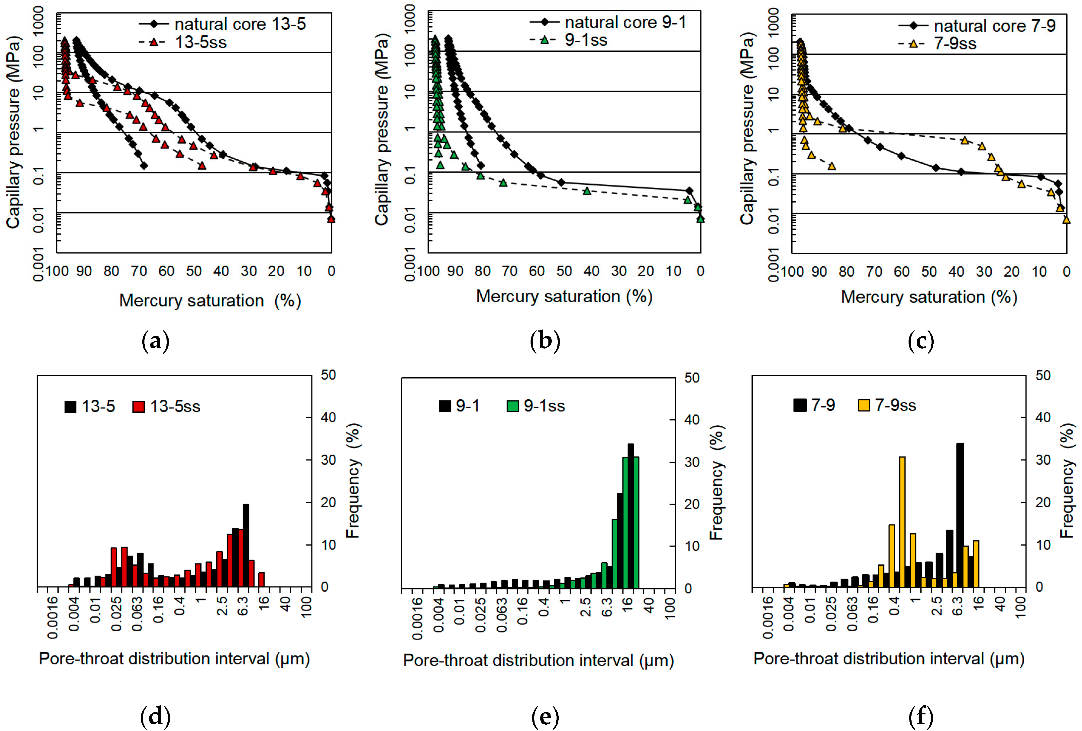
Following the method for adjustment of the pore throat size distribution data in the methods above, the results of the pore throat size distribution of the synthetic sandstone try for the three target samples are shown in Figure 13 plotted in comparison to their corresponding targets. For the synthetic sandstone samples, analysis of the MICP curve shown in Figure 13a–c suggests that the initial displacement pressure for all of them are close to the target indicating the biggest pores of the targets were matched well. Additionally, the residual saturation of synthetic sandstones all came within 5% of the target suggesting that the smallest pore-throats are modeled to within a close tolerance as well. Analysis of the pore throat size distribution results in Figure 13d–f suggests that the pore throat size distribution of the synthetic sandstone match well to that of the targets (with the exception of slight deviation in sample 7-9) in the 0.004–25 μm (full micro–messo–macro porosity) range. The bi-modal vs. uni-modal distribution curves of the target samples were captured very well by the synthetic sandstone samples. The slight mismatch in pore-throat distribution of the synthetic sandstone 7–9 to the target suggests that a lower amount of fine sand is probably warranted to shift the pore throat size distribution more to the right as shown in Figure 13.

3.9. The Match of the Cementation Level: Validation by SEM

After confirmation of the pore throat size distribution match. The synthetic samples were then sent for scanning electron microscopy (SEM) for characterization of the level of cementation. Figure 14 shows the SEM results of the target sandstone on top with their corresponding synthetic sandstone counterpart immediately below. All samples are displayed at 150× magnification. Target sample 9-1 in Figure 14a with the largest porosity and permeability exhibits the clearest particle morphology with the least amount of intergranular fillings resulting in most of the porosity remaining as the intergranular porosity. Target sample 9-1 also exhibits the best connectivity under low magnification. Target sample 7-9 in Figure 14b has intermediate connectivity with a relatively developed pore network, but with clear signs of a more advanced level of cementation. Target sample 13-5 in Figure 14c has the poorest pore network with the most extensive amount of cementation found in all pore space under low magnification. The synthetic sample 9-1 in Figure 14d shows also the clearest rock morphology corresponding to their lowest cementation level of 10% 2000# sand. The trend of the increasing cementation level of 2000# sand up to 26–30% and the corresponding change of the loss of intergranular porosity seen in the synthetic samples 7-9 in Figure 14e and 13-5 in Figure 14f match well to their natural sandstone target counterpart. Overall, the trend of cementation increase expected of lower permeability samples as shown in the target sample is also reflected in their synthetic counterparts.

4. Summary and Discussion

As a summary, a method of making synthetic sandstone with concurrent multi-parametric physical modeling of the dominant mineral composition, particle size distribution, wettability, porosity, pore throat size distribution, permeability, and capillary pressure behavior to a natural unfractured homogeneous sandstone target is introduced in this work. This methodology entails a step-wise approach that seeks to start the modeling from the most fundamental parameters first following a sequential order of physical modeling of mineralogy, particle size distribution, packing, and cementation as illustrated by the methodological flow chart in Figure 3. A primary difference between this work and previous work is that the synthetic sandstone physical model detailed in this work is targeted after a specific natural homogeneous unfractured sandstone with its ensemble of unique petrophysical parameters. This work is not just a method of making synthetic sandstone, but a method to make a very sophisticated physical model targeting an actual rock of interest with a comparable match to most of the relevant major petrophysical properties of interest to researchers. The path to achieving this very close concurrent multi-parametric physical modeling is another key difference from the previous studies in that this work is theoretically-driven. This work has a very clear methodology guided by a clear physical interaction pathway model. Following this methodology, the whole ensemble of relevant physical parameters shown in Figure 2 in a target homogeneous unfractured sandstone can be concurrently modeled to a tight tolerance. This is a significant improvement from the previous studies which are mostly limited to a try-and-see type of efforts with no specific target. The agreement of particle size distribution, wettability, porosity, permeability, pore throat distribution, and capillary pressure results of the synthesized rock to that of their targets in this paper give support to this assertion.
Previous studies in synthetic porous media-related research contributed valuable insights on identifying the independent fundamental parameters that are of importance for physical modeling of the natural porous media. This work goes a step further in linking the independent fundamental petrophyiscal parameters together with their dependent physical parameters into a coherent theoretical framework. By identifying the four independent petrophysical parameters from a thin section analysis, and deduced that the rest of the dependent pore network-derived parameters can be physically modeled through adjustment of the four, the authors reported a workable and scientific method of achieving the concurrent multi-parametric physical modeling of unfractured homogeneous sandstone in the permeability range of 88–1186×10−3µm2. The improvement in physical modeling shown in this work is currently limited to only conventional reservoir types. This methodology is currently nonapplicable to unconventionals reservoirs such as shale and tight oil reservoirs due to the synthesis problems with increasing cementation level required as target porosity decreased below 20%. The physical model made according to this methodology can be highly adaptable and specific to a target lithological formation. By physically modeling the key parameters mentioned in this work to a specific target, the test relevancy for the corefloods or petrophysical testing can have very high data relevancy. As a renewable substitute for target formation with tailorable dimensions, this advanced physical model can be cut into different shapes and made into a heterogeneous model by joining sections of different petrophysical properties together for mechanistic studies [37].
Future extension of this work involves a better way to model more complex chemical fluid-rock interaction and extending the same physical modeling capability to carbonate systems.

5. Conclusions

A methodology for a theoretically-driven bottom-up approach to physically model a target unfractured homogeneous sandstone is introduced. For the first time, a methodology on how to simultaneously physically model multiple physical parameters of common interests to researchers including particle size distribution, wettability, porosity, pore throat size distribution, permeability, capillary pressure behavior in a target formation is introduced. This work is the first work in outlining a clear theoretical framework on how these physical parameters are interrelated and using it as a guideline for guiding synthetic sandstone synthesis.
Using the method detailed here, by concentrating on physically modeling of the four independent physical parameters of mineralogy, particle size distribution, packing, and cementation, the rest of the dependent physical parameters of wettability, porosity, permeability, capillary pressure, and pore-throat distribution can be simultaneously modeled comparably well to the target The span error of particle size distribution came within 30%. The porosity and permeability matched to within 2% and 10% error, respectively to the target. The midrange error of wettability came within 23%. The pore throat distribution matched very closely to that of the target. Both entry pressure and residual water saturation of the capillary pressure curve matched to within 5% of the target. In comparison to sand packs and substitute outcrop with low clay content (e.g., Berea sandstone), synthetic sandstone made with the method introduced here offer better data relevancy for transport in porous media-related research and testing due to its better tailorability to match the key petrophysical parameters of a specific lithological formation of interest.

Author Contributions

Conceptualization, J.Y.F. and X.Y.; methodology, J.Y.F. and B.Z.; validation, J.Y.F., B.Z. and X.Y.; formal analysis, J.Y.F. and B.Z.; investigation, J.Y.F. and B.Z.; resources, X.Y.; data curation, J.Y.F. and B.Z.; writing—original draft preparation, J.Y.F.; writing—review and editing, J.Y.F. and X.Y.; visualization, J.Y.F.; supervision, J.Y.F.; project administration, J.Y.F.; funding acquisition, X.Y. All authors have read and agreed to the published version of the manuscript.

Funding

This study was financially supported by the National Science and Technology Major Project of China, grant number 2016ZX05050010; the National Natural Science Foundation of China grant number 5133407; Science Foundation of China University of Petroleum-Beijing, grant number 2462017YJRC026.

Acknowledgments

We are grateful to the editor and the reviewers for their comments, which improved substantially the quality of the manuscript

Conflicts of Interest

The authors declare no conflict of interest.

References

  1. Ghosh, J.; Geoffrey, R.T.; Akyol, N.H.; Zhang, Y. A pore-scale investigation of heavy crude oil trapping and removal during surfactant-enhanced remediation. J. Contam. Hydrol. 2019, 223, 10347. [Google Scholar] [CrossRef] [PubMed]
  2. Sharma, P.; Kostarelos, K.; Lenschow, S.; Christensen, A.; de Blanc, P.C. Surfactant flooding makes a comeback: Results of a full-scale, field implementation to recover mobilized NAPL. J. Contam. Hydrol. 2020, 230, 103602. [Google Scholar] [CrossRef] [PubMed]
  3. Bai, M.; Liu, L.; Li, C.; Song, K. Relative Permeability Characteristics During Carbon Capture and Sequestration Process in Low-Permeable Reservoirs. Materials 2020, 13, 990. [Google Scholar] [CrossRef] [Green Version]
  4. Sun, Y.; Li, Q.; Yang, D.; Liu, X. Laboratory core flooding experimental systems for CO2 geosequestration: An updated review over the past decade. J. Rock Mech. Geotech. Eng. 2016, 8, 113–126. [Google Scholar] [CrossRef] [Green Version]
  5. Aadland, R.C.; Jakobsen, T.D.; Heggset, E.B.; Long-Sanouiller, H.; Simon, S.; Paso, K.G.; Syverud, K.; Torsæter, O. High-Temperature Core Flood Investigation of Nanocellulose as a Green Additive for Enhanced Oil Recovery. Nanomaterials 2019, 9, 665. [Google Scholar] [CrossRef] [Green Version]
  6. Vorhauer, N.; Altaf, H.; Tsotsas, E.; Vidakovic-Koch, T. Pore Network Simulation of Gas-Liquid Distribution in Porous Transport Layers. Processes 2019, 7, 558. [Google Scholar] [CrossRef] [Green Version]
  7. Vorhauer-Huget, N.; Altaf, H.; Dürr, R.; Tsotsas, E.; Vidaković-Koch, T. Computational Optimization of Porous Structures for Electrochemical Processes. Processes 2020, 8, 1205. [Google Scholar] [CrossRef]
  8. Keshmiri, K.; Mozaffari, S.; Tchoukov, P.; Huang, H.; Nazemifard, N. Using Microfluidic Device to Study Rheological Properties of Heavy Oil. In Proceedings of the 2016 AIChE Annual Meeting, San Francisco, CA, USA, 14 November 2016. [Google Scholar]
  9. Mozaffari, S.; Tchoukov, P.; Mozaffari, A.; Atias, J.; Czarnecki, J.; Nazemifard, N. Capillary driven flow in nanochannels–Application to heavy oil rheology studies. Colloids Surf. A Physicochem. Eng. Asp. 2017, 513, 178–187. [Google Scholar] [CrossRef]
  10. Churcher, P.L.; French, P.R.; Shaw, J.C.; Schramm, L.L. Rock Properties of Berea Sandstone, Baker Dolomite, and Indiana Limestone. In Proceedings of the SPE International Symposium on Oilfield Chemistry, Anaheim, CA, USA, 1 January 1991. [Google Scholar] [CrossRef]
  11. Abdelgawad, K.Z.; Mahmoud, M.; Elkatatny, S.; Abdulraheem, A.; Patil, S. Reaction Kinetics and Coreflooding Study of High-Temperature Carbonate Reservoir Stimulation Using GLDA in Seawater. Energies 2019, 12, 3407. [Google Scholar] [CrossRef] [Green Version]
  12. Brattekås, B.; Føyen, T.L.; Vabø, T.; Haugland, H.; Reite, S.I.; Saunes, A.S.; Fernø, M.A. Dos and don’ts when developing a system to investigate spontaneous imbibition in unconsolidated porous media. In Proceedings of the International Symposium of the Society of Core Analysts, Trondheim, Norway, 27–30 August 2018. [Google Scholar]
  13. Ronan, L. An NMR Investigation to Pore Size and Paramagnetic Effect in Synthetic Sandstone. Ph.D. Thesis, University of Western Australia, Perth, Australia, 2006. [Google Scholar]
  14. Shi, L.; Zhu, S.; Guo, Z.; Zhao, W.; Xue, X.; Wang, X.; Ye, Z. Experimental Study on the Effect of Polymer Injection Timing on Oil Displacement in Porous Media. Processes 2020, 8, 93. [Google Scholar] [CrossRef] [Green Version]
  15. Shi, J.Q.; Xue, Z.; Durucan, S. Supercritical CO2 core flooding and imbibition in Tako sandstone—Influence of sub-core scale heterogeneity. Int. J. Greenh. Gas Control 2011, 5, 75–87. [Google Scholar] [CrossRef]
  16. Al-Homadhi, E.S. Artificial Sandstone Cores Production with a Wide Range of Petrophysical Properties. J. King Saud Univ. Eng. Sci. 2002, 14, 95–117. [Google Scholar] [CrossRef]
  17. Fedrizzi, R.M.; Rodrigues de Ceia, M.A.; Misságia, R.M.; Santos, V.H.; Neto, I.L. Artificial carbonate rocks: Synthesis and petrophysical characterization. J. Pet. Sci. Eng. 2018, 163, 303–310. [Google Scholar] [CrossRef]
  18. den Brok, S.W.J.; David, C.; Bernabé, Y. Preparation of synthetic sandstones with variable cementation for studying the physical properties of granular rocks. C. R. Acad. Sci. Ser. IIa Sci. Terre Planetes 1997, 325, 487–492. [Google Scholar] [CrossRef]
  19. Kozhagulova, A.A.; Shabdirova, A.D.; Tokazhanov, G.; Minh, N.H. Bond Characteristics of Artificial Sandstones with sodium silicate cement. In Proceedings of the 52nd U.S. Rock Mechanics/Geomechanics Symposium, Seattle, WA, USA, 17–20 June 2018. [Google Scholar]
  20. Klimentos, T.; Parker, A. The preparation (by an epoxy-resin method) and physical properties of artificial sandstones. Sediment. Geol. 1988, 59, 307–312. [Google Scholar] [CrossRef]
  21. Holt, R.M.; Unander, T.E.; Kenter, C.J. Constitutive mechanical behaviour of synthetic sandstone formed under stress. Int. J. Rock Mech. Min. Sci. Geomech. Abstr. 1993, 30, 719–722. [Google Scholar] [CrossRef]
  22. Mozaffari, S.; Li, W.; Dixit, M.; Seifert, S.; Lee, B.; Kovarik, L.; Mpourmpakis, G.; Karim, A.M. The role of nanoparticle size and ligand coverage in size focusing of colloidal metal nanoparticles. Nanoscale Adv. 2019, 1, 4052–4066. [Google Scholar] [CrossRef] [Green Version]
  23. Ghasemi, H.; Aghabarari, B.; Alizadeh, M.; Khanlarkhani, A.; Abu-Zahra, N. High efficiency decolorization of wastewater by Fenton catalyst: Magnetic iron-copper hybrid oxides. J. Water Process. Eng. 2020, 37, 101540. [Google Scholar] [CrossRef]
  24. Guo, W.; Xiao, H.; Yao, X.; Liu, J.; Liang, J.; Gao, P.; Zeng, G. Tuning pore structure of corrosion resistant solid-state-sintered SiC porous ceramics by particle size distribution and phase transformation. Mater. Des. 2016, 100, 1–7. [Google Scholar] [CrossRef] [Green Version]
  25. Rashidi, S.; Kashefi, M.H.; Kim, K.C.; Samimi-Abianeh, O. Potentials of porous materials for energy management in heat exchangers—A comprehensive review. Appl. Energy 2019, 243, 206–232. [Google Scholar] [CrossRef]
  26. Rashidi, S.; Esfahani, J.A.; Karimi, N. Porous materials in building energy technologies—A review of the applications, modelling and experiments. Renew. Sustain. Energy Rev. 2018, 91, 229–247. [Google Scholar] [CrossRef]
  27. Yang, K.; Li, J.; Zhou, L.; Zhang, T.; Fu, L. Synthetic strategies of two-dimensional porous materials towards highly effective catalysts. FlatChem 2019, 15, 100109. [Google Scholar] [CrossRef]
  28. Su, J.; Chen, J.S. Synthetic porous materials applied in hydrogenation reactions. Microporous Mesoporous Mater. 2017, 237, 246–259. [Google Scholar] [CrossRef]
  29. Costa, S.E.D.; Barros Neto, E.L.; Oliveira, M.C.A.; Santos, J.S.C. Mechanical and petrophysical analysis of synthetic sandstone for enhanced oil recovery applications. Braz. J. Pet. Gas 2017, 11, 131–140. [Google Scholar] [CrossRef] [Green Version]
  30. Schäfer, A.; Teyssen, T. Size, shape and orientation in sands and sandstones-image analysis applied to rocks in thin sections. Sediment. Geol. 1987, 52, 3. [Google Scholar] [CrossRef]
  31. Deng, Y.; Hao, W.H.; Lu, W.L. The contact angle of water on feldspar in a reservoir rock. Chin. Sci. Bull. 2018, 63, 3137–3145. [Google Scholar] [CrossRef]
  32. Deng, Y.; Xu, L.; Lu, H.; Wang, H.; Shi, Y. Direct Measurement of the Contact Angle of Water Droplet on Quartz in a Reservoir Rock with Atomic Force Microscopy. Chem. Eng. Sci. 2017, 177. [Google Scholar] [CrossRef]
  33. Sharifipour, M.; Pourafshary, P.; Nakhaee, A. Study of the effect of clay swelling on the oil recovery factor in porous media using a glass micromodel. Appl. Clay Sci. 2017, 141, 125–131. [Google Scholar] [CrossRef]
  34. Kamal, M.S.; Mahmoud, M.; Hanfi, M.; Elkatatny, S.; Hussein, I. Clay minerals damage quantification in sandstone rocks using core flooding and NMR. J. Pet. Explor. Prod. Technol. 2019, 9, 593. [Google Scholar] [CrossRef] [Green Version]
  35. ASTM. Standard Test Method for Determination of Pore Volume and Pore Volume Distribution of Soil and Rock by Mercury Intrusion Porosimetry; ASTM (American society for Testing and Materials): West Conshohocken, PA, USA, 1984; pp. 4404–4484, reapproved 1998. [Google Scholar]
  36. Shafer, J.; Neashman, J. Mercury porosimetry protocol for rapid determination of petrophysical and reservoir quality properties. In Proceedings of the Society of Core Analysts, Abu Dhabi, UAE, 18–20 October 2000. [Google Scholar]
  37. Fu, J.Y.; Yue, X.A.; Li, L.; Zhang, L. Method of Predicting the Location of Water Cresting for Horizontal Wells in a Water-Drive Reservoir for Early Prevention. ACS Omega 2020, 5, 26153–26168. [Google Scholar] [CrossRef]
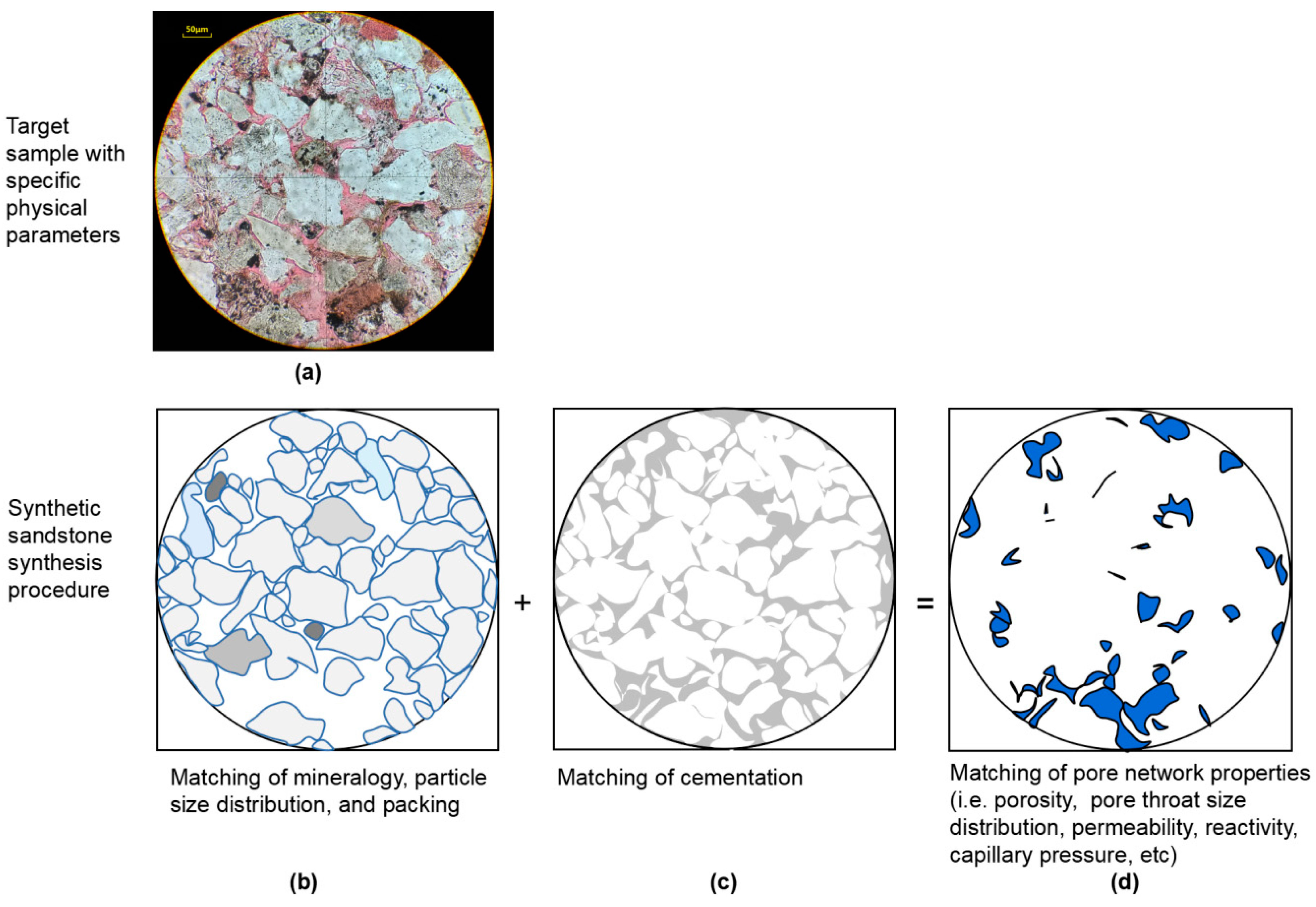
Figure 1. (a) Thin section of target natural sandstone sample 7-1 incorporating the four independent fundamental physical parameters of particle size distribution, packing, cementation, and mineral composition. Synthetic sandstone synthesis procedure with (b) match of particle size distribution (particle size distribution (PSD); shown in gray), mineral composition, packing, and (c) Match of cementation level (shown in gray) resulting in (d) match of pore network (shown in blue), and its derived pore network-associated properties.
Processes 08 01448 g001
Figure 2. Physical parametric interaction pathways of the major petrophysical parameters in sedimentary rock affecting the chromatographic/transport/storage/chemical behavior of petroleum fluids and water (solid lines are rock properties).
Processes 08 01448 g002
Figure 3. Methodological flow chart for concurrent multi-parametric physical modeling of an unfractured homogeneous sandstone.
Processes 08 01448 g003
Figure 4. Equipment for making synthetic sandstone: (a) mechanical sieve with an automatic feeder; (b) 20 L mechanical mixer; (c) 500-ton hydraulic press; (d) coring drill/table saw.
Processes 08 01448 g004aProcesses 08 01448 g004b
Figure 5. (a) A 30 cm × 30 cm × 7 cm synthetic sandstone block; (b) cored/squared synthetic sandstone samples.
Processes 08 01448 g005
Figure 6. Loose sand processing for matching of the particle size distribution for sample 9-1, 7-9 and 13-5. Solid lines with Δ, ◊, ○ are particle size distribution of target natural cores 9-1, 13-5, and 7-9 respectively by thin section testing. The dotted lines (---) in the figures are particle size distribution of 80–120# sands sieved at different mesh size by laser diffraction particle size distribution testing.
Processes 08 01448 g006
Figure 7. The match of particle size distribution by thin section analysis. The solid lines with ▲, ♦, ● are particle size distribution of the target natural cores 9-1, 13-5, and 7-9 respectively by thin section testing. The dotted line with Δ, ◊, ○ are the particle size distribution of their corresponding synthetic sandstone by thin section testing.
Processes 08 01448 g007
Figure 8. (ac) The contact angles of target samples; (df) the contact angles of synthetic samples at standard conditions.
Processes 08 01448 g008
Figure 9. Permeability and porosity vs. pressure. Permeability curve is plotted with Δ, and porosity curve is plotted with ●.
Processes 08 01448 g009
Figure 10. Porosity vs. 2000 mesh sand ratio for rough adjustment of cementation in synthetic sandstone samples.
Processes 08 01448 g010
Figure 11. Permeability vs. 2000 mesh sand ratio for fine adjustment of cementation in synthetic sandstone samples.
Processes 08 01448 g011
Figure 12. The control of the pore throat size distribution through adjustment of cementation level in the intergranular space with use of fine sands shown by the mercury injection capillary pressure (MICP) testing. On the left hand side are the MICP curve showing an increasing amount of fine sand ratio in the direction pointed by the arrow for two cases. (a) A coarser increment of fine sand with 0%, 4%, and 6% fine sand (♦, ▲, ● respectively); (b) A finer increment with an increase of 0.33%, 0.66%, and 1% fine sands (♦, ▲, ● respectively). (c,d) The right-hand side shows the pore throat size distribution derived from the MICP data showing that as the ratio of fine sand increase, the pore throat size distribution ratio move toward the smaller pore throat size.
Processes 08 01448 g012
Figure 13. The comparison of the MICP (ac) and the pore-throat distribution (df) results of the synthetic sandstone to the target. The solid lines in the top figures with ♦ are the MICP curves of the target natural cores of 9-1, 13-5, and 7-9. The color line in the top figures are the MICP curves of the synthetic sandstone counterpart. The figures at the bottom are the pore throat size distribution of the target samples shown in black compared to their synthetic sandstone counterpart in color.
Processes 08 01448 g013
Figure 14. The scanning electron microscopy image of the targets: (a) 9-1, (b) 7-9, and (c) 13-5 and their synthetic sandstone counterpart (d) 9-1ss, (e) 7-9ss, and (f) 13-5ss.
Processes 08 01448 g014
Table 1. Compositional analysis by X-ray diffraction (XRD).
SampleMineral Composition (%)
QuartzPotassium-FeldsparPlagioclase-FeldsparCalciteDolomiteRock SaltClay
9-151.711.427.7//2.86.4
13-555.410.122.1///12.4
7-951.18.43002.40.77.4
Publisher’s Note: MDPI stays neutral with regard to jurisdictional claims in published maps and institutional affiliations.