1. Introduction
The blast furnace (BF) route still remains the dominant one in the production of liquid iron, which is the primary raw material for large-scale steelmaking. In recent years, the trend has been to construct larger furnaces and close small and inefficient ones. Along with the growth of furnace size, more liquid iron and slag are also stored in the BF hearth, and problems of draining and wear are encountered more frequently in the practical operation. Furthermore, due to tougher global competition, the furnace campaign lengths should be extended, and the furnace body should withstand operation under production rates that vary with the market conditions. It is today commonly recognized that drainage and wear problems in the hearth region play the key role in determining the BF campaign life [
1].
Both practical and theoretical investigations have revealed that most of the draining and wear problems in the hearths of large furnaces are related to the state and behavior of the porous coke beds that fill them, i.e., the dead man. In order to fully utilize the potential of large BFs in terms of high productivity and lower unit costs of production, it is of considerable significance to understand the governing mechanisms of the dead man behavior in the BF hearth. However, knowledge and information about the dead man are still severely limited, mainly due to the fact that the hearth is the most inaccessible part of the BF, lacking direct measurements. Nevertheless, a number of publications related to or addressing different aspects of the dead man can be found in the literature. The purpose of the current brief review is to summarize these results in a comprehensive document, where the main emphasis is put on presenting contributions shedding light on the dead man state and assessing its influence on BF hearth performance, with respect to liquid flow patterns, hearth lining wear and drainage behavior. The basic modeling approaches used in the analysis are also briefly treated.
2. Investigations and Modeling of the Dead Man
The internal state of the BF, as schematically illustrated in
Figure 1, has been gradually revealed by extensive dissection investigations [
2,
3], which confirmed that there exists a stagnant column of coke particles in the lower part of the furnace. The stagnant column, where coke particles move downwards with a highly reduced velocity, was called “dead man” because it was earlier assumed to exert negligible influence on the whole ironmaking process [
4]. However, this assumption was later been found to be incorrect. As a matter of fact, it is nowadays commonly believed that the dead-man state significantly affects the gas and liquid flows in the BF lower part, which, in turn, determine the temperature distribution within the hearth, the liquid drainage, as well as wear of the hearth lining [
5]. In addition, the dead man appears to be rather “active” since it is usually claimed to have an average porosity of
[
2], and can be renewed in periods varying between a few days and some weeks.
2.1. Structure and Renewal of the Dead Man
As depicted in
Figure 1, the dead man is located under the active coke zone beneath the cohesive zone. The upper part of the dead man, which is in the region between the raceways, is cone-shaped with a rounded top. The inclination from the apex of the dead man to the raceway plane is usually claimed to be associated with the repose angle of the coke particles that are charged [
6], but also other factors (e.g., charging pattern [
7], gas and liquid flow rates) may influence its state. Traditionally, the solid flow has been studied via small-scale experiments, but along with the emergence of more efficient software and hardware, it has recently become feasible to study the dead man formation and the flow of coke in the hearth via the Discrete Element Method (DEM).
The lower part of the dead man is in the region of the hearth where liquid iron and slag dripping from the cohesive zone accumulate before they are tapped out intermittently. Thus, the lower part of the dead man is submerged in a bath of liquid iron and slag, and is thus subjected to a buoyancy force that depends on how deeply the coke is submerged in the two liquids. Because of this, it is not straightforward to deduce the bottom shape and position of the dead man, especially taking into account the dynamic changes in the liquid levels during the tap cycle, as well as other operation variables that may affect or interact with the buoyancy force. In principle, the bottom shape and position of the dead man can be estimated by balancing the forces acting on the dead man, whereby the buoyancy force (often) varies with the liquid levels. A majority of the studies on the estimation of the dead man bottom shape and position are summarized in a separate subsection. In this context, it should be mentioned that some authors use the term dead man only referring to its lower part (i.e., the region below the tuyere level), while others use the broader definitions used above (cf.
Figure 1).
In the upper part beneath the active coke zone, the renewal of the dead man is relatively fast due to the short distance to the raceways where coke is intensively consumed. It has been clarified that there exists a small quasi-stagnant region in the center of the active coke zone where the coke particles descend slowly towards the raceways. Therefore, the dead-man porosity (and permeability) can be improved by feeding high-quality coke into the BF center [
8,
9,
10]. It was also reported that the dead man can be lifted with a sufficient buoyancy force, and the coke right beneath the tuyere level can be “pushed” into the raceways. Renewal thus occurs as the “old” particles are forced to go out of the dead man and “new” particles enter to fill the voids through the upper surface of the dead man [
11,
12,
13,
14,
15]. In the lower part, especially below the taphole level, it is, however, difficult for the coke to flow upwards into the raceways. Various other renewal mechanisms have been presented and the prevailing ones include FeO reduction, carbon solution loss and carbonization of liquid iron [
16,
17,
18,
19,
20]. Data from a radioactive tracer test indicated that coke in the peripheral region within the hearth is consumed in 2–3 days, due to a more intensive flow of liquid iron that dissolves coke carbon. This number can be deduced from a simple carbon balance of the hearth, as follows: Consider a large BF with a hearth diameter of 14 m and a daily production rate of 9000 tons, where the hearth coke (85% carbon) occupies about 1000 m
3, with a dead man voidage of
. If the iron that enters the hearth has a carbon content of 2.5% and a content of 4.5% at tapping, an average renewal rate of about 3 days is obtained. However, in the core region of the dead man, the coke is much more gradually dissolved, which is often claimed to occur within a few weeks [
3]. It is expected that the dead man in the hearth is heterogeneous with respect to permeability, since the renewal processes are all strongly dominated by liquid flow and heat transfer, which are usually non-uniform in the hearth [
21]. Another aspect that indicates a non-uniform permeability distribution is that smaller coke particles may move up and down with the hearth liquids in the voids formed between larger coke particles [
5].
The permeability of the dead man can be estimated qualitatively by studying the residence time distribution of tracers injected through a tuyere, or via a probe inserted into the dead man at the tuyere level. The tracer particles dissolve in the iron and/or the slag and are measured in the runner afterwards. By analyzing the response of the tracer in the outflow, information about the flow pattern inside the hearth can be obtained. If the tracer particles are injected at different locations along the radius using a probe, the residence time can be used to evaluate the permeability of different zones of the hearth coke. In some industrial trials with radioactive coke particles, it was found that the core of the dead man in the hearth was very impermeable [
22,
23].
2.2. Floating State of the Dead Man
The bottom shape and position of the dead man depend on the liquid levels in the hearth and on the force acting on the bed from above. In a normal tap cycle, the liquid levels vary with varying outflow rates of iron and slag, due to the intermittent tapping, as the taphole is eroded during tapping, and because of the “competition” between iron and slag flow in the taphole [
24]. Mainly based on balance equations of mass and force, the liquid levels in the BF hearth with two different dead man floating states were estimated and are shown in
Figure 2, where the corresponding filtered electromotive force (emf) signals measured at the hearth shell are also depicted [
25]. By comparison of simulated liquid levels and emf, Brännbacka [
26] found that the iron level corresponds better to the emf signal. Comparing the maxima of the iron and slag level with the emf, this observation can also be confirmed in
Figure 2. However, it should be mentioned that the variation in true liquid levels is very hard to measure, even though some indirect measuring methods have been proposed [
27,
28,
29].
In an operating furnace, the dead man state in the hearth cannot be measured directly or monitored, owing to the high temperatures, wear, and extremely hostile environment. The dynamic behavior of the dead man has therefore mainly been investigated by utilizing scale models and/or mathematical models under simplified conditions. By visual inspection, it was found that the dead man moves vertically in a cyclic manner during a tap cycle [
11,
30]. The dead man sits completely on the hearth bottom (i.e., fully fills the hearth) when the liquid levels measured from the hearth bottom are low, while it floats to some degree of height or fully if the liquid levels are high, thus creating a free passage (i.e., coke-free zone) for the liquid flow. Since the iron, with a density of about 2.5 times that of slag, exerts a stronger buoyancy, it is generally considered that the distance between the hearth bottom and the inner end of the taphole (“sump depth”) is decisive for dead man floating [
31]. In the experimental runs with a pilot model where air was blown in through several tuyeres located in the sidewall and particles were discharged near the tuyeres (in order to mimic the coke consumption by combustion), the dead-man bottom was demonstrated to assume a profile with higher floating levels near the sidewall. This bottom shape has been confirmed in a set of quenched furnaces and two examples are presented in [
32,
33].
A sophisticated mathematical model [
34] also taking into account BF hearth geometry and operation parameters categorized the floating state of the dead man into four different groups: (A) completely floating with a flat bottom, (B) completely floating, but floating higher near the wall, (C) partly floating at the wall, and (D) completely sitting. The results are shown in
Figure 3a, where the hearth depth is defined as the distance between hearth bottom and the taphole level. It can be seen that the floating state of the dead man depends strongly on the hearth (“sump”) depth and liquid level. The corresponding conditions of some Japanese furnaces were also examined by the mathematical model. As elucidated in
Figure 3, the prevailing conditions (i.e., types B and C) of Japanese furnaces appear left of the vertical dashed line, while the aforementioned floating type A (i.e., completely floating with a flat bottom profile) appears right of the dashed vertical line, and is thus in conflict with the prevailing conditions.
2.3. Modeling of Dead Man State
The dead-man state can be estimated by conducting a balance between the buoyancy of iron and slag in the hearth and the force pressing down on the dead man. The buoyancy force, which is a function of liquid level and dead man porosity, is relatively straightforwardly expressed. Nevertheless, the vertical force pressing down on the dead man is more complicated, since it is related to a set of furnace operating conditions, e.g., raceway length, gas drag and burden weight, as well as liquid holdup above the hearth liquids [
34]. The BF lower part is schematically illustrated in
Figure 4, where the dead man is divided into two particular regions based on the raceway length/gas drag intensity, i.e., a central region and a region under raceways [
35].
It should be stressed that both the buoyancy force and the downward-acting force are often expressed per unit area, i.e., in the form of pressure. The downward-acting stress at the tuyere level (cf.
Figure 4), which was investigated by conducting both experimental runs and numerical calculations [
34], is depicted in
Figure 5. As can be seen in the figure, the stress is highly reduced in the region where the raceway is located. This can be explained by the drag of the upward-flowing gas from the raceway, which compensates for a portion of the burden weight above the tuyere level. In the region under the raceways, consequently, the dead man could float higher if the buoyancy force is sufficient.
As the radial distribution of the downward-acting force per area,
, may vary with the operating conditions, Brännbacka et al. [
25,
26,
36,
37,
38] suggested the simple but flexible parameterized expression
where
,
and
are the overall downward pressure, radial position as well as radius of the central region where the downward-acting pressure is unaffected by the raceways, respectively.
is the hearth radius and
is a scaling factor, while
is a parameter that influences the arising shape of the dead man bottom under the raceways. The magnitude of the overall force can be obtained by calculating the burden weight as reduced by the lifting force of the gas drag and the friction of the furnace wall. The vertical position of the dead man bottom deduced from the force balance is
with
where
,
,
g and
are the densities of liquid iron and slag, gravitational acceleration and the vertical position of the hearth bottom, respectively, while
,
and
are the dead-man porosity and the levels of liquid iron and slag, respectively.
If the parameters of Equation (1) are given, the dead man bottom profile can be calculated based on the quantities of hearth liquids and an average dead man porosity.
Figure 6 shows the estimated evolution of the iron and slag levels and the bottom shape of the dead man during a tap cycle in a BF, where the inner hearth profile was estimated by solving an inverse heat transfer problem [
25]. The corresponding three-dimensional coke-free zones beneath the dead man are depicted in
Figure 7, where the black bar indicates the location of the taphole.
2.4. Effect of Dead Man State on Hearth Performance
2.4.1. Liquid Flow Pattern and Flow-Induced Shear Stress
In the hearth, the floating state of the dead man plays a key role in determining the lining wear and the pattern of liquid flow [
31]. Through dissections of quenched furnaces and based on observations at the campaign end when the hearth is relined, the wear profile of the hearth lining has been investigated. The profiles reported in such investigations usually indicate an elephant-foot-shaped profile with severe erosion of the lining in the lower periphery of the hearth. It has been recognized that an elephant-foot-shaped profile is caused by the intensive circumferential flow of hot metal that can occur when the permeability in the dead man’s core deteriorates and/or the dead man floats partly, forming a coke-free zone (“gutter”) at the hearth corner [
39,
40]. A bowl-shaped profile, where the lining in the middle of the hearth bottom is excessively eroded, has also been reported. This pattern could be the result if the dead man floats completely, or if the porosity of the dead man is fairly uniform and it occupies the whole hearth. The latter can be expected for hearth designs where the sump depth is large.
The pattern of liquid flow in the BF hearth has been investigated by using both physical and numerical models. Physical studies utilizing scale models have usually considered only steady-state iron flow through a heterogeneous dead man with zones of different permeability. The modeling results can still give insightful information concerning the liquid flow close to the hearth bottom, where the lining erosion is mainly attributed to iron flow.
A number of computational fluid dynamics (CFD) models, focusing on the phenomena in the BF hearth and considering liquid flow and/or heat transfer, have also been built in the past. Usually, the dead man is taken as a fixed packed bed, and Darcy’s/Ergun’s equation can be applied. The influences of dead man properties, such as packing structure and floating state, on the liquid flow paths and distribution of temperature in the hearth lining have been thoroughly evaluated [
41,
42,
43,
44,
45,
46,
47,
48,
49,
50].
Figure 8 (based on unpublished results using the model outlined in [
48]) illustrates the general streamlines of hot metal in one half of the hearth. These results indicate that a partly floating dead man leads to an intensive circumferential flow, thus exerting a strong heat load on the lining at the hearth corner. However, some simulation results have implied that the distribution of temperature at the hearth bottom is less sensitive to the dead man’s properties, since the local heat transfer is controlled by the high thermal resistance of the hearth lining refractories (i.e., ceramic pad) [
47].
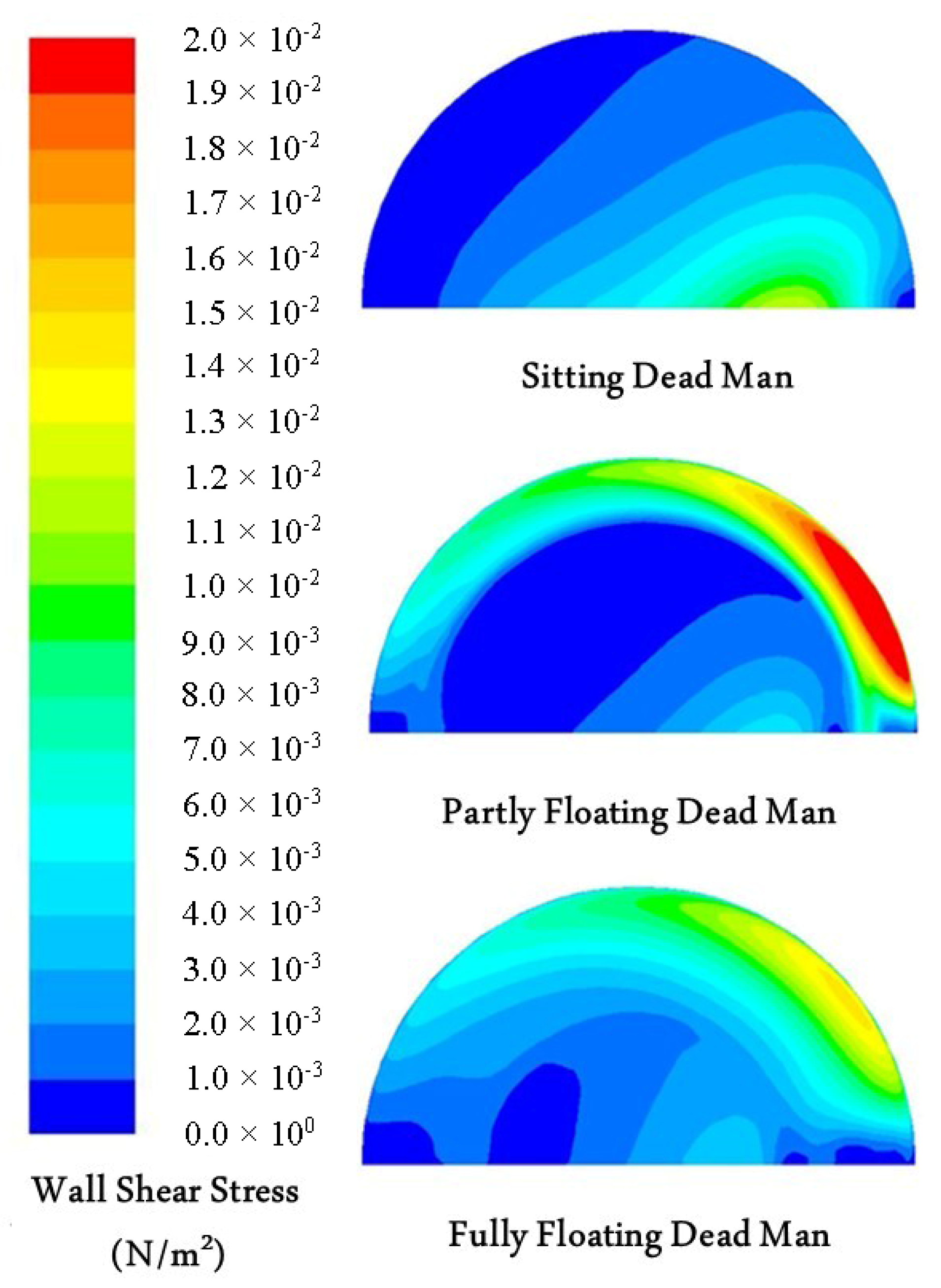
The possible hearth lining wear mechanisms include chemical reactions between the lining materials and molten liquids, abrasion and friction caused by coke particles in the hearth, as well as thermo-mechanical stress and flow-induced shear stress. The last one that is caused by the near-wall flow field can lead to lining erosion alone, and a combination of it with other mechanisms could give rise to more wear, eventually resulting in severe hearth damage. Thus, it is imperative to understand the shear stress in terms of its generation and distribution so that appropriate precautions can be taken to reduce the shear stress in order to prolong the campaign life of the hearth. The flow-induced shear stress has been studied mainly using CFD models, since no direct measurements of the BF hearth state variables exist [
48,
49,
50,
51,
52,
53]. The contours of the shear stress on the hearth bottom under different dead man states, calculated in [
48,
49], are depicted in
Figure 9. It can be seen that with a sitting dead man, the high shear stress zone emerges in the interior of the hearth bottom, particularly below the taphole entrance. Nevertheless, the zone moves to the peripheral region when the dead man partly floats, with a coke-free zone emerging at the hearth corner. In addition, a fully floating dead man state could mitigate the hearth bottom shear stress to some extent, since the shear stress distributes quite uniformly. This would imply that in furnaces where the dead man has started floating completely, the hearth bottom erosion would not progress much.
It was also reported that the high shear stress and heat load in the vicinity of the taphole can be effectively reduced with a longer taphole, since the overall liquid flow is forced to bend towards the center of the dead man, and the circumferential flow caused by a partly floating dead man, or a dead man with a blocked core, can be restrained [
52]. This is actually the main reason why a long taphole is usually a prerequisite for protecting the hearth lining near the taphole from severe erosion. A long taphole is often associated with a high carbon content of the liquid iron, which supports the above hypothesis. Furthermore, it has been demonstrated [
35] that to achieve a longer taphole, the injected mud must be in good contact with the dead man. Thus, if the dead man floats excessively at the wall, the taphole becomes short, and severe sidewall erosion may follow. In summary, the dead man state is strongly associated with hearth lining erosion, as discussed in the following subsection.
2.4.2. Hearth Wear Profile
The internal geometry of the scale models and the computational domains that represent the hearth profile have usually been simple and regular in physical experiments and in CFD simulations. However, as discussed above, the inner hearth profile may assume different states, partly as a result of the dead-man state. When the hearth lining is cooled at the cold face, the local temperature and velocity of liquid iron in the vicinity of the hot face could become insufficient to keep the iron in liquid form. As a result, the iron may gradually solidify, forming a skull layer on the hot surface of the remaining lining. Therefore, as is often seen by observing the evolution of thermocouples embedded in the hearth lining, the internal geometry of the hearth varies during the campaign [
54].
In view of the inherent coupling between liquid flow and heat transfer, an intensive circumferential flow leading to severe erosion is usually linked with an increased heat load on the hearth lining materials. Temperatures measured by thermocouples embedded in the hearth lining can therefore be utilized to predict the hearth wear profile. In practice, the 1150 °C isotherm is often regarded as the internal liquid–solid interface in the hearth. In order to estimate this isotherm, mathematical models where an inverse problem of heat transfer is solved have been proposed [
31,
54]. It should be stressed that 1150 °C is the lowest temperature at which carbon-saturated iron is present in liquid form, and consequently only heat conduction is solved in this kind of hearth wear profile model. A basic algorithm for estimating the hearth wear profile is outlined in
Figure 10.
As a rule, wear models detect the inner profile of the intact lining by matching the most severe erosion experienced during the campaign. If later points correspond to less severe erosion, this is taken as an indication of the formation of a skull layer. It is still a complicated task to accurately identify the remaining sound lining and the skull thickness, particularly for cases wherein the historical thermocouple readings are not available for the whole furnace campaign. A systematic and two-dimensional approach is needed in order to estimate the progress of erosion, and also the formation of skull, during the campaign [
31,
54,
55]. The erosion and skull lines estimated with such an approach for two different BFs (unpublished results using the model outlined in [
55]) are presented in
Figure 11. It can be seen that the two furnaces have different but characteristic wear profiles, i.e., bowl-shaped and elephant-foot-shaped profiles, which are likely to reflect the state of the iron flow in or below the dead man during the campaigns.
Hearth wear profile estimation models are commonly implemented as monitoring and diagnosis tools to aid the operation of BFs. By analyzing the estimated hearth wear profile, indications may be obtained pertaining to the need to adjust the operation towards conditions less prone to cause erosion, e.g., by reducing the production rate or by blanking tuyeres. The latter means both reducing the local inflow of iron “from above” and suppressing a possible local floating of the dead man. On the other hand, it may be argued that such blanking may instead promote liquid flow, as the liquid holdup decreases at a lower local bosh gas flow. It seems that the efficiency of such actions depends on the state of the furnace when the change is implemented.
The estimated erosion profile can be used to support the interpretation of the liquid flow pattern and dead man floating state that are intimately related to hearth erosion. For instance, a too strong peripheral flow or too low carbon content of the hot metal may be counteracted by the center charging of strong and large coke, which (in the long run) will promote a more uniform flow of iron through the dead man, enhancing the contact of it with the hearth wall. Still, it should be kept in mind that the accuracy of erosion models depends on the validity of the modeling assumptions. In particular, brittle lining layers of low conductivity may lead to inaccurate estimates of the progress of the erosion profile, and the occurrence of such should be detected by other means [
56,
57].
2.4.3. Drainage Behavior
In the BF hearth, the void space is occupied by the immiscible liquid iron and slag. As a result of gravity, the rivulets of molten iron and slag from the cohesive zone [
58] will eventually separate into two different layers, i.e., the upper slag layer and the lower iron layer. Two interfaces, i.e., gas–slag and slag–iron, are thus formed in the hearth. In practice, a tap starts when one taphole is drilled open. A substantial pressure drop in the vicinity of the taphole can be formed as the high-viscosity slag is driven to flow through the dead man towards the taphole. As a result, the gas–slag interface is tilted down locally near the taphole [
24,
59,
60,
61,
62]. Thus, the overall gas–slag interface is above the taphole level at the moment when gas bursts out and the tap is terminated. This is actually the reason why some amount of slag still remains in the hearth at the tap end, and a “dry hearth” is impossible in practice.
It was earlier commonly assumed that the slag–iron interface is horizontal at the level of the taphole when the slag phase approaches the taphole during tapping. Based on this assumption, extensive physical experiments were carried out by Fukutake and Okabe in order to estimate the tap end slag residual ratio [
63,
64,
65]. By analyzing the experimental results mainly using the theories of fluid dynamics, the authors proposed a dimensionless flow-out coefficient that was found to correlate monotonically with the slag residual ratio defined. The flow-out coefficient is strongly affected by the state of the dead man, including its voidage and coke particle size. Later, the aforementioned assumption of a horizontal slag–iron interface was found to be incorrect, since both practical observations and physical experiments with two immiscible liquids indicated that the lower phase (liquid iron) can be pumped up from some level below the taphole during the period when slag and iron are drained out simultaneously [
59,
66,
67]. In the BF hearth, a substantial pressure drop is induced in the taphole vicinity when the high-viscosity slag flows through the dead man. This large pressure drop is sufficient to compensate for the flow resistance of the low-viscosity iron, and to overcome the gravitational force when iron is drained up from some level below the taphole. The iron and slag levels at the end of a tap in the BF hearth are sketched in
Figure 12, where the hearth internal profile is idealized.
The flow-out coefficient [
63,
64,
65] was later modified by other authors [
68,
69] to take into account the non-horizontal slag–iron interface as it is depicted in
Figure 12, the coke-free zone beneath the dead man, the varying drainage rates of iron and slag due to taphole erosion, and the continuous production of the liquids. Both observations in the practical operation of the hearth and CFD-based simulations [
70,
71] have shown that an increase in the slag residual ratio is often attributed to a decrease in dead man permeability, or an increase in draining rate or in slag viscosity. It has also been found that a coke-free zone beneath the dead man directly affects hearth drainage only if it extends close to or above the taphole level [
32,
68,
72]. However, even a partial floating of the dead man may have implications for the drainage via the accumulation and depletion of liquid iron in the coke-free zone during the tap cycle, which affects the liquid levels [
25,
37,
38] and therefore the pressure-loss terms of iron and slag in front of the taphole [
24].
With reference to
Figure 12, the asymptotic relation between the tap end iron and slag levels that are related to the dead man state can be derived based on a simplified pressure balance [
66,
67]:
where
and
are the vertical distance and liquid density, and where subscripts ir, sl and e denote iron, slag and tap end, respectively.
Equation (4) has been adopted as an asymptotic relation in some hearth drainage studies to validate the calculated results [
25,
73]. It should, however, be noted that the end points of individual taps may depart considerably from the above relation, simply because the “initial” volume of slag is not sufficient: if too little slag is drained, the duration of the tap is not long enough for the liquids to reach this asymptotic state. The occurrence of local liquid levels in a BF with an impermeable dead man further complicates the general interpretation [
62,
74,
75,
76].
3. Concluding Remarks
Over the years, several aspects regarding the BF dead man have been studied by means of dissection investigations, physical experiments, and theoretical and numerical calculations. Today, the importance of the dead man state and its influence on the performance of the BF hearth have been commonly recognized, even though direct (long-term) measurements of the pertaining state variables are still impossible.
The structure and renewal mechanisms of the dead man have been clarified. It has been demonstrated that the dead man is heterogeneous in terms of its permeability distribution, and that the permeability can be improved in practice by charging high-quality coke into the BF center. The dead man bottom shape and position strongly depend on the balance between the buoyancy force exerted by the in-hearth liquid iron and slag, and the downward-acting force that is reduced towards the furnace wall due to the drag of the upward-flowing gas from the raceways and wall friction. In general, the dead man sits completely on the hearth bottom when the levels of the in-hearth liquids are low. If the liquid levels are high, however, the dead-man bottom assumes a profile where it floats higher at the hearth corner.
Observed hearth lining wear profiles, i.e., elephant-foot-shaped and bowl-shaped, are intimately related to the dead man floating state and its permeability distribution. The lining profile can be estimated utilizing hearth wear models, whereby an inverse problem of heat conduction is solved to predict the position of the 1150 °C isotherm. Such models are today used in several BFs as monitoring and diagnosis tools. The estimated profile can be used to assist the interpretation of the in-hearth liquid flow pattern and the floating state of the dead man. By analyzing the estimated hearth wear profile, indications may also be obtained pertaining to the need to change the operation towards conditions less prone to cause erosion, including lowering of the production rate, blanking of tuyeres in regions with strong local hearth wear, or modifying the tapping strategy.
The drainage of the BF hearth is complicated and a dry tap is impossible because some amount of slag always remains in the hearth at the end of a normal tap. It has been shown that the slag residual ratio at the tap end can be correlated with the flow-out coefficient. In practice, an increase in the slag residual ratio is often attributed to a decrease in dead man permeability, or an increase in draining rate or in slag viscosity. The complexity of the hearth drainage behavior is basically due to the multiphase flow of immiscible fluids (gas, slag and iron), the existence of the dead man and the erosion of the taphole. As a tap proceeds, both the gas–slag and slag–iron interfaces gradually tilt towards the taphole. Therefore, the overall slag and iron levels are located above and below the taphole at the tap-end, respectively. This interface titling phenomenon has been investigated, and an absolute asymptotic limit has been derived and can be applied to validate the related modeling results. However, much work is still required in order to understand the effects of, e.g., local permeability changes in the dead man or local dead man motion on the drainage patterns from individual tapholes. A deeper understanding of the drainage can be the basis of a better design of the tapping operation, which can be influenced by the duration of the inter-cast period, the drill diameter and the taphole angle. The role of the taphole length, e.g., how this variable can be controlled and how it affects the dead-man state, are also factors that should be studied and clarified in the future.
Author Contributions
Conceptualization, L.S. and H.S.; literature review, L.S., Q.X., C.Z., Z.Z. and H.S., original draft preparation, L.S.; writing—review and editing, L.S., Z.Z. and H.S.; funding acquisition, L.S. and Z.Z. All authors have read and agreed to the published version of the manuscript.
Funding
This research was partially funded by the National Science Foundation of China, grant number 51604068. The authors gratefully acknowledge the support.
Conflicts of Interest
The authors declare no conflict of interest. The funders had no role in the design of the study or interpretation of the results.
References
- Liu, Z.J.; Zhang, J.L.; Zuo, H.B.; Yang, T.J. Recent progress on long service life design of Chinese blast furnace hearth. ISIJ Int. 2012, 52, 1713–1723. [Google Scholar] [CrossRef]
- Kanbara, K.; Hagiwara, T.; Shigemi, A.; Kondo, S.; Kanayama, Y.; Wakabayashi, K.; Hiramoto, N. Dissection of blast furnaces and their internal state. Trans. Iron Steel Inst. Jpn. 1977, 17, 371–380. [Google Scholar] [CrossRef]
- Omori, Y. Blast Furnace Phenomena and Modelling; Elsevier: London, UK, 1987. [Google Scholar]
- Nishio, H.; Wenzel, W.; Gudenau, H.W. Significance of the dead (man) zone in the blast furnace. Stahl Eisen. 1977, 97, 867–875. [Google Scholar]
- Nightingale, R.J. The Development and Application of Hearth Voidage Estimation and Deadman Cleanliness Index for the Control of Blast Furnace Hearth Operation. Ph.D. Thesis, University of Wollongong, New South Wales, Australia, January 2000. [Google Scholar]
- Raipala, K. On Hearth Phenomena and Hot Metal Carbon Content in Blast Furnace. Ph.D. Thesis, Helsinki University of Technology, Helsinki, Finland, November 2003. [Google Scholar]
- Ichida, M.; Nishihara, K.; Tamura, K.; Sugata, M.; Ono, H. Influence of ore/coke distribution on descending and melting behavior of burden in the blast furnace. ISIJ Int. 1991, 31, 505–514. [Google Scholar] [CrossRef]
- Takahashi, H.; Komatsu, N. Cold model study on burden behaviour in the lower part of blast furnace. ISIJ Int. 1993, 33, 655–663. [Google Scholar] [CrossRef][Green Version]
- Takahashi, H.; Tanno, M.; Katayama, J. Burden descending behavior with renewal of deadman in a two dimensional cold model of blast furnace. ISIJ Int. 1996, 36, 1354–1359. [Google Scholar] [CrossRef]
- Nogami, H.; Toda, K.; Pintowantoro, S.; Yagi, J.I. Cold-model experiments on deadman renewal rate due to sink-float motion of hearth coke bed. ISIJ Int. 2004, 44, 2127–2133. [Google Scholar] [CrossRef]
- Shibata, K.; Kimura, Y.; Shimizu, M.; Inaba, S. Dynamics of dead-man coke and hot metal flow in a blast furnace hearth. ISIJ Int. 1990, 30, 208–215. [Google Scholar] [CrossRef]
- Shinohara, K.; Saitoh, J. Mechanism of solids segregation over a two-dimensional dead man in a blast furnace. ISIJ Int. 1993, 33, 672–680. [Google Scholar] [CrossRef][Green Version]
- Zhang, S.J.; Yu, A.B.; Zulli, P.; Wright, B.; Austin, P. Numerical simulation of solids flow in a blast furnace. Appl. Math. Modell. 2002, 26, 141–154. [Google Scholar] [CrossRef]
- Kawai, H.; Takahashi, H. Solid behavior in shaft and deadman in a cold model of blast furnace with floating-sinking motion of hearth packed bed studied by experimental and numerical DEM analyses. ISIJ Int. 2004, 44, 1140–1149. [Google Scholar] [CrossRef]
- Bambauer, F.; Wirtz, S.; Scherer, V.; Bartusch, H. Transient DEM-CFD simulation of solid and fluid flow in a three dimensional blast furnace model. Powder Technol. 2018, 334, 53–64. [Google Scholar] [CrossRef]
- Sunahara, K.; Inada, T.; Iwanaga, Y. Size degradation of deadman coke by reaction with molten FeO in blast furnace. ISIJ Int. 1993, 33, 275–283. [Google Scholar] [CrossRef][Green Version]
- Kasai, A.; Kiguchi, J.; Kamijo, T.; Shimizu, M. Degradation of coke by molten iron oxide in the cohesive zone and dripping zone of a blast furnace. Tetsu-to-Hagané 1998, 84, 9–13. [Google Scholar] [CrossRef]
- Sun, H. Analysis of reaction rate between solid carbon and molten iron by mathematical models. ISIJ Int. 2005, 45, 1482–1488. [Google Scholar] [CrossRef]
- Li, K.; Zhang, J.; Liu, Y.; Barati, M.; Liu, Z.; Zhong, J.; Yang, T. Graphitization of coke and its interaction with slag in the hearth of a blast furnace. Metall. Mater. Trans. B 2016, 47, 811–813. [Google Scholar] [CrossRef]
- Post, J.R. Simulation of the Inhomogeneous Deadman of an Ironmaking Blast Furnace. Ph.D. Thesis, Delft University of Technology, Delft, The Netherlands, November 2019. [Google Scholar]
- Sugiyama, T. Experimental and numerical analysis on the movement and the accumulation of powder in the deadman and the dripping zone of blast furnace. Tetsu-to-Hagané 1996, 82, 29–34. [Google Scholar] [CrossRef]
- Raipala, K. Deadman and hearth phenomena in the blast furnace. Scand. J. Metall. 2000, 29, 39–46. [Google Scholar] [CrossRef]
- Negro, P.; Petit, C.; Urvoy, A.; Sert, D.; Pierret, H. Characterization of the permeability of the blast furnace lower part. Revue Métallurgie 2001, 98, 521–531. [Google Scholar] [CrossRef]
- Roche, M.; Helle, M.; van der Stel, J.; Louwerse, G.; Storm, J.; Saxén, H. Drainage model of multi-taphole blast furnace. Metall. Mater. Trans. B 2020, 51, 1731–1749. [Google Scholar] [CrossRef]
- Brännbacka, J.; Saxén, H. Novel model for estimation of liquid levels in the blast furnace hearth. Chem. Eng. Sci. 2004, 59, 3423–3432. [Google Scholar] [CrossRef]
- Brännbacka, J. Model Analysis of Dead-Man Floating State and Liquid Levels in the Blast Furnace Hearth. Ph.D. Thesis, Åbo Akademi University, Turku, Finland, October 2004. [Google Scholar]
- Desai, D. Analysis of blast furnace hearth drainage based on the measurement of liquid pressure inside of the hearth. Iron Steelmak. 1992, 19, 52–57. [Google Scholar]
- Danloy, G.; Stolz, C.; Crahay, J.; Dubois, P. Measurement of iron and slag levels in blast furnace hearth. In Proceedings of the 58th Ironmaking Conference, Chicago, IL, USA, 21–24 March 1999; pp. 89–98. [Google Scholar]
- Havelange, O.; Danloy, G.; Franssen, C. The dead man, floating or not? Revue Métallurgie 2004, 101, 195–201. [Google Scholar] [CrossRef]
- Shinotake, A.; Ichida, M.; Ootsuka, H.; Kurita, Y. Bottom shape of blast furnace deadman and its floating/sinking behavior by 3-dimensional model experiment. Tetsu-to-Hagané 2003, 89, 573–580. [Google Scholar] [CrossRef]
- Andreev, K.; Louwerse, G.; Peeters, T.; van der Stel, J. Blast furnace campaign extension by fundamental understanding of hearth processes. Ironmak. Steelmak. 2017, 44, 81–91. [Google Scholar] [CrossRef]
- Nouchi, T.; Yasui, M.; Takeda, K. Effects of particle free space on hearth drainage efficiency. ISIJ Int. 2003, 43, 175–180. [Google Scholar] [CrossRef]
- Inada, T.; Kasai, A.; Nakano, K.; Komatsu, S.; Ogawa, A. Dissection investigation of blast furnace hearth—Kokura No. 2 Blast Furnace (2nd campaign). ISIJ Int. 2009, 49, 470–478. [Google Scholar] [CrossRef]
- Takahashi, H.; Kawai, H.; Suzuki, Y. Analysis of stress and buoyancy for solids flow in the lower part of a blast furnace. Chem. Eng. Sci. 2002, 57, 215–226. [Google Scholar] [CrossRef]
- Tsuchiya, N.; Fukutake, T.; Yamauchi, Y.; Matsumoto, T. In-furnace conditions as prerequisites for proper use and design of mud to control blast furnace taphole length. ISIJ Int. 1998, 38, 116–125. [Google Scholar] [CrossRef]
- Brännbacka, J.; Saxén, H. Modeling the liquid levels in the blast furnace hearth. ISIJ Int. 2001, 41, 1131–1138. [Google Scholar] [CrossRef]
- Brännbacka, J.; Saxén, H. Model analysis of the operation of the blast furnace hearth with a sitting and floating dead man. ISIJ Int. 2003, 43, 1519–1527. [Google Scholar] [CrossRef]
- Brännbacka, J.; Torrkulla, J.; Saxén, H. Simple simulation model of blast furnace hearth. Ironmak. Steelmak. 2005, 32, 479–486. [Google Scholar] [CrossRef]
- Takeda, K.; Watakabe, S.; Sawa, Y.; Itaya, H.; Kawai, T.; Matsumoto, T. Prevention of hearth brick wear by forming a stable solidified layer. Ironmak. Steelmak. 2000, 27, 79–84. [Google Scholar]
- Li, Y.; Cheng, S.; Zhang, P.; Zhou, S. Sensitive influence of floating state of blast furnace deadman on molten iron flow and hearth erosion. ISIJ Int. 2015, 55, 2332–2341. [Google Scholar] [CrossRef]
- Ohno, J.; Tachimori, M.; Nakamura, M.; Hara, Y. Influence of hot metal flow on the heat transfer in a blast furnace hearth. Tetsu-to-Hagané 1985, 71, 34–40. [Google Scholar] [CrossRef]
- Preuer, A.; Winter, J.; Hiebler, H. Computation of the erosion in the hearth of a blast furnace. Steel Res. 1992, 63, 147–151. [Google Scholar] [CrossRef]
- Preuer, A.; Winter, J. Numerical simulation of refractory erosion caused by carbon dissolution in blast furnace. Revue Métallurgie 1993, 90, 955–964. [Google Scholar] [CrossRef]
- Inada, T.; Takatani, K.; Miyahara, M.; Wakabayasi, S.; Yamamoto, T.; Kasai, A.; Takata, K. Development and application of an advanced numerical analysis technology for blast furnace hearth. In Proceedings of the 58th Ironmaking Conference, Chicago, IL, USA, 21–24 March 1999; pp. 633–639. [Google Scholar]
- Panjkovic, V.; Truelove, J.S.; Zulli, P. Numerical modelling of iron flow and heat transfer in blast furnace hearth. Ironmak. Steelmak. 2002, 29, 390–400. [Google Scholar] [CrossRef]
- Guo, B.Y.; Yu, A.B.; Zulli, P.; Maldonado, D. CFD modelling and analysis of the flow, heat transfer and mass transfer in a blast furnace hearth. Steel Res. Int. 2011, 82, 579–586. [Google Scholar] [CrossRef]
- Guo, B.Y.; Maldonado, D.; Zulli, P.; Yu, A.B. CFD modelling of liquid metal flow and heat transfer in blast furnace hearth. ISIJ Int. 2008, 48, 1676–1685. [Google Scholar] [CrossRef]
- Shao, L.; Saxén, H. Numerical prediction of iron flow and bottom erosion in the blast furnace hearth. Steel Res. Int. 2012, 83, 878–885. [Google Scholar] [CrossRef]
- Shao, L. Model-Based Estimation of Liquid Flows in the Blast Furnace Hearth and Taphole. Ph.D. Thesis, Åbo Akademi University, Turku, Finland, September 2013. [Google Scholar]
- Cheng, W.T.; Huang, E.N.; Du, S.W. Numerical analysis on transient thermal flow of the blast furnace hearth in tapping process through CFD. Int. Commun. Heat Mass Transf. 2014, 57, 13–21. [Google Scholar] [CrossRef]
- Vats, A.K.; Dash, S.K. Flow induced stress distribution on wall of blast furnace hearth. Ironmak. Steelmak. 2000, 27, 123–128. [Google Scholar] [CrossRef]
- Dash, S.K.; Ajmani, S.K.; Kumar, A.; Sandhu, H.S. Optimum taphole length and flow induced stresses. Ironmak. Steelmak. 2001, 28, 110–116. [Google Scholar] [CrossRef]
- Dash, S.K.; Jha, D.N.; Ajmani, S.K.; Upadhyaya, A. Optimisation of taphole angle to minimise flow induced wall shear stress on the hearth. Ironmak. Steelmak. 2004, 31, 207–215. [Google Scholar] [CrossRef]
- Torrkulla, J.; Saxén, H. Model of the state of the blast furnace hearth. ISIJ Int. 2000, 40, 438–447. [Google Scholar] [CrossRef]
- Brännbacka, J.; Saxén, H. Model for fast computation of blast furnace hearth erosion and buildup profiles. Ind. Eng. Chem. Res. 2008, 47, 7793–7801. [Google Scholar] [CrossRef]
- Shinotake, A.; Nakamura, H.; Yadoumaru, N.; Morizane, Y.; Meguro, M. Investigation of blast-furnace hearth sidewall erosion by core sample analysis and consideration of campaign operation. ISIJ Int. 2003, 43, 321–330. [Google Scholar] [CrossRef]
- Kaymak, Y.; Bartusch, H.; Hauck, T.; Mernitz, J.; Rausch, H.; Lin, R. Multiphysics model of the hearth lining state. Steel Res. Int. 2020, 200055. [Google Scholar] [CrossRef]
- Wang, G.X.; Chew, S.J.; Yu, A.B.; Zulli, P. Model Study of Liquid Flow in the Blast Furnace Lower Zone. ISIJ Int. 1997, 37, 573–582. [Google Scholar] [CrossRef]
- Tanzil, W.B.; Zulli, P.; Burgess, J.M.; Pinczewski, W.V. Experimental model study of the physical mechanisms governing blast furnace hearth drainage. Trans. Iron Steel Inst. Jpn. 1984, 24, 197–205. [Google Scholar] [CrossRef]
- Shao, L.; Saxén, H. Pressure drop in the blast furnace hearth with a sitting deadman. ISIJ Int. 2011, 51, 1014–1016. [Google Scholar] [CrossRef]
- Shao, L.; Saxén, H. A simulation study of two-liquid flow in the taphole of the blast furnace. ISIJ Int. 2013, 53, 988–994. [Google Scholar] [CrossRef][Green Version]
- Saxén, H. Model of draining of the blast furnace hearth with an impermeable zone. Metall. Mater. Trans. B 2015, 46, 421–431. [Google Scholar] [CrossRef]
- Fukutake, T.; Okabe, K. Investigation of slag flow in the blast furnace hearth based on the fluid dynamics and of relation between residual slag amount and tapping out conditions. Tetsu-to-Hagané 1974, 60, 607–621. [Google Scholar] [CrossRef]
- Fukutake, T.; Okabe, K. Experimental studies of slag flow in the blast furnace hearth during tapping operation. Trans. Iron Steel Inst. Jpn. 1976, 16, 309–316. [Google Scholar] [CrossRef]
- Fukutake, T.; Okabe, K. Influences of slag tapping conditions on the amount of residual slag in blast furnace hearth. Trans. Iron Steel Inst. Jpn. 1976, 16, 317–323. [Google Scholar] [CrossRef]
- Tanzil, W.B.U. Blast Furnace Hearth Drainage. Ph.D. Thesis, University of New South Wales, Sydney, Australia, 1985. [Google Scholar]
- Tanzil, W.B.U.; Pinczewski, W.V. Blast furnace hearth drainage: Physical mechanisms. Chem. Eng. Sci. 1987, 42, 2557–2568. [Google Scholar] [CrossRef]
- Zulli, P. Blast Furnace Hearth Drainage with and without Coke-Free Layer. Ph.D. Thesis, University of New South Wales, Sydney, Australia, 1991. [Google Scholar]
- Bean, I. Blast Furnace Hearth Drainage. Improvement of the Residual-Flowout Correlation. Ph.D. Thesis, University of New South Wales, Sydney, Australia, September 2008. [Google Scholar]
- Nishioka, K.; Maeda, T.; Shimizu, M. A three-dimensional mathematical modelling of drainage behavior in blast furnace hearth. ISIJ Int. 2005, 45, 669–676. [Google Scholar] [CrossRef]
- Nishioka, K.; Maeda, T.; Shimizu, M. Effect of various in-furnace conditions on blast furnace hearth drainage. ISIJ Int. 2005, 45, 1496–1505. [Google Scholar] [CrossRef]
- Nouchi, T.; Sato, M.; Takeda, K.; Ariyama, T. Effects of operation condition and casting strategy on drainage efficiency of the blast furnace hearth. ISIJ Int. 2005, 45, 1515–1520. [Google Scholar] [CrossRef][Green Version]
- Shao, L.; Saxén, H. A simulation study of blast furnace hearth drainage using a two-phase flow model of the taphole. ISIJ Int. 2011, 51, 228–235. [Google Scholar] [CrossRef]
- Iida, M.; Ogura, K.; Hakone, T. Analysis of drainage rate variation of molten iron and slag from blast furnace during tapping. ISIJ Int. 2008, 48, 412–419. [Google Scholar] [CrossRef]
- Iida, M.; Ogura, K.; Hakone, T. Numerical study on metal/slag drainage rate deviation during blast furnace tapping. ISIJ Int. 2009, 49, 1123–1132. [Google Scholar] [CrossRef]
- Roche, M.; Helle, M.; van der Stel, J.; Louwerse, G.; Shao, L.; Saxén, H. Off-line model of blast furnace liquid levels. ISIJ Int. 2018, 58, 2236–2245. [Google Scholar] [CrossRef]
| Publisher’s Note: MDPI stays neutral with regard to jurisdictional claims in published maps and institutional affiliations. |
© 2020 by the authors. Licensee MDPI, Basel, Switzerland. This article is an open access article distributed under the terms and conditions of the Creative Commons Attribution (CC BY) license (http://creativecommons.org/licenses/by/4.0/).


