Article

Numerical Investigation of the Effect of Incorporated Guide Vane Length with SCC Piston for High-Viscosity Fuel Applications

by
Mohd Fadzli Hamid
1,
Mohamad Yusof Idroas
1,
Mazlan Mohamed
2,
Shukriwani Sa'ad
3,
Teoh Yew Heng
1,
Sharzali Che Mat
4,
Muhamad Azman Miskam
1,
Zainal Alimuddin Zainal Alauddin
1 and
Muhammad Khalil Abdullah
5,*
1
School of Mechanical Engineering, Universiti Sains Malaysia, Engineering Campus, Seri Ampangan, Nibong Tebal 14300, Pulau Pinang, Malaysia
2
Advanced Material Research Cluster, Faculty of Bioengineering and Technology, Universiti Malaysia Kelantan, Jeli 17600, Kelantan, Malaysia
3
Faculty of Computer, Media and Technology Management, TATI University College, Kijal 24000, Kemaman, Terengganu, Malaysia
4
Faculty of Mechanical Engineering, Universiti Teknologi Mara, Pulau Pinang, Permatang Pauh 13500, Pulau Pinang, Malaysia
5
School of Material and Mineral Resources Engineering, Universiti Sains Malaysia, Engineering Campus, Seri Ampangan, Nibong Tebal 14300, Pulau Pinang, Malaysia
*
Author to whom correspondence should be addressed.
Processes 2020, 8(11), 1328; https://doi.org/10.3390/pr8111328
Submission received: 7 September 2020 / Revised: 29 September 2020 / Accepted: 1 October 2020 / Published: 22 October 2020
(This article belongs to the Special Issue CFD Applications in Energy Engineering Research and Simulation)

Abstract

:
Compression ignition (CI) engines that run on high-viscosity fuels (HVF) like emulsified biofuels generally demonstrate poor engine performance. An engine with a consistently low performance, in the long run, will have a negative effect on its lifespan. Poor combustion in engines occurs mainly due to the production of less volatile, less flammable, denser, and heavier molecules of HVF during injection. This paper proposes a guide vane design (GVD) to be installed at the intake manifold, which is incorporated with a shallow depth re-entrance combustion chamber (SCC) piston. This minor modification will be advantageous in improving the evaporation, diffusion, and combustion processes in the engine to further enhance its performance. The CAD models of the GVD and SCC piston were designed using SolidWorks 2018 while the flow run analysis of the cold flow CI engine was conducted using ANSYS Fluent Version 15. In this study, five designs of the GVD with varying lengths of the vanes from 0.6D (L) to 3.0D (L) were numerically evaluated. The GVD design with 0.6D (L) demonstrated improved turbulence kinetic energy (TKE) as well as swirl (Rs), tumble (RT), and cross tumble (RCT) ratios in the fuel-injected zone compared to other designs. The suggested improvements in the design would enhance the in-cylinder airflow characteristics and would be able to break up the penetration length of injection to mix in the wider area of the piston-bowl.

1. Introduction

Diesel engines, otherwise known as the compression ignition (CI) engines are widely used in industrial, commercial transportation, agricultural, watercraft propulsion power, and non-road construction applications, particularly in off-grid situations [1]. To date, petro-diesel fuels have dominated as the preferred fuel in CI engines [2]. However, the periodic shortage of petroleum, fluctuations in petroleum price in the global market, and strict regulations on vehicular emissions in several countries have encouraged automotive manufacturers, scientists, and researchers to look for an alternative source that could replace existing fossil fuels [3]. Modern lifestyle and rapid development in urban areas have surged the global demand for fossil fuels to approximately 53%, according to the report of the International Energy Agency [4]. For this reason, the challenges in the new era of the twenty-first century are to resolve the dependency on fossil fuels and to minimize the emission of exhaust pollutants for the sake of human civilization.
Biofuel is a potential fuel alternative since it can be easily extracted from various feedstocks such as plants, vegetable oil, edibles/non-edibles, and animal fats. The similarity in the properties of biofuel and petro-diesel make the former an attractive source to replace the conventional petro-diesel fuel [5]. The commercial production of biofuel has been reported as an economically feasible process, with an added advantage of improved emission characteristics [6]. Although the burning of biofuel could reduce the emissions of pollutants such as soot, particulate matter (PM), carbon monoxide (CO), and total hydrocarbon (THC); nevertheless, the emission of nitrogen oxide (NOx) is still high due to the higher auto-ignition temperature of biofuel than that of petro-diesel [7]. The problem can be alleviated by enforcing biofuel emulsification, wherein the biofuel burning and thermal inefficiency in the combustion chamber are improved.
Numerous reports have shown that emulsified biofuel emits lower emissions of CO2, NOx, and CO compared to neat biofuels [8,9,10]. Prakash et al. investigated the engine performance and emissions from burning emulsified Jatropha methyl ester (JME), wherein about 35% of the reduction was observed in the HCs emissions compared to that of neat JME [11]. In another study, it was found that CO2 emission was lower in higher load operated engines using emulsified Jatropa blends as fuel [12]. In general, the emission level of emulsified biofuels may vary based on the level of water concentration.
Generally, the direct use of biofuels without modification either in their properties or the engine compartment is not recommended as it may lead to inferior engine performance, increased build-up of carbon, injector choking, filter clogging, excessive fuel consumption, and reduced lifespan [13]. Similar outcomes can also be ascribed to the biofuel properties, such as higher viscosity, lower volatility, higher density, and presence of heavier molecules during injection. High viscosity fuels are less prone to evaporation, thus detrimental to the air-fuel mixture in the cylinder. Furthermore, on using neat biofuel without modifications, a build-up of carbon deposits in the piston-bowl and cylinder wall were found on disassembling the engine [14]. However, when the biofuel properties were modified closer to the physiochemical properties of petro-diesel, for instance, biodiesel, a higher thermal efficiency compared to that of petro-diesel, was observed. It is due to the presence of oxygen molecules and different auto-ignition constituents in the biodiesel itself [15].
In order to improve the performance and reduce the emission of CI engines to run on high viscosity fuel, particularly biofuels, researchers introduced various techniques to improve and resolve the above-mentioned problems. Some of the popular techniques to reduce the viscosity of biofuels are preheating of the biofuels at a specific temperature [16], blending the biofuel with petro-diesel [17], and double-blending of biofuel with different cetane numbers [18]. In the engine configuration, modifications of piston-bowl, intake manifold, and injection pressure and timing to suit the applications of biofuel were investigated [3,19]. Meanwhile, in the modification of the physicochemical properties of the biofuel, techniques such as emulsification, double-blending with different viscosity fluid, and transesterification were introduced [20]. All of these techniques were proven to improve the performance and emission of CI engines, yet their performance when using biofuel was still lower compared to that of petro-diesel [21]. So far, very few studies related to the modification of in-cylinder airflow characteristics to enhance the engine performance and reduce the emissions when running on high viscosity fuels like emulsified biofuel have been conducted.
Studies to improve the in-cylinder airflow characteristics inside the engine combustion chamber are beneficial as their capabilities to stimulate and break down the highly viscous fuel during the injection stage could be investigated [22]. Furthermore, the penetration length of spraying can be reduced, and the spreading angle along the piston-bowl can be enhanced. Several designs to improve the engine in-cylinder airflow were proposed by researchers, such as baffles or butterfly valves, intake runners, guide vane design (GVD), combustion chamber designs, and piston bowl geometry designs. Among the proposed designs, GVD signifies the simplest design with a promising improvement of in-cylinder airflow compared to other designs [23]. GVD also escapes the need for an extensive physical modification on CI engines. Therefore, this study suggests that the GVD will improve CI engines in terms of swirl, turbulence, kinetic energy, tumble, and cross tumble ratios. However, none of the researchers had explored the idea of combining GVD with piston geometry design to enhance the in-cylinder airflow characteristics and regulate fluid flow inside the combustion chamber.
In this paper, the identified research gap has been considered by investigating the in-cylinder airflow characteristics using the combination of guide vane design (GVD) and piston bowl design of the shallow depth combustion chamber (SCC) type to enhance and regulate the in-cylinder airflow characteristics of CI engines. Concerning GVD, the four main parameters of the study are vane height, vane angle, vane number, and vane length. However, this research is limited to optimizing the length of the vane, while the other parameters were kept constant at fixed values based on the findings from previous studies [24,25,26]. As for the piston bowl design, the SCC type was selected since it is capable of generating uniform fluid flow throughout the piston-bowl design, as suggested by several researchers [27,28,29].

2. Computer Simulation

SolidWorks 2018, a computer-aided drawing software, was used in this research to draw the GVD and SCC piston-bowl design. ANSYS FLUENT 15, a computational fluid dynamics (CFD) analysis software, was employed to simulate the CI engine. The simulation was conducted based on three stages: the SCC piston-bowl design, base model, and GVD with various lengths of the vane. The simulation of the CI engine is comprised of four main steps, namely, drawing the model, meshing the elements, setting up the boundary conditions, and computing the CI engine airflow characteristics. The details of the constructed computer simulation models are discussed in the following sections.

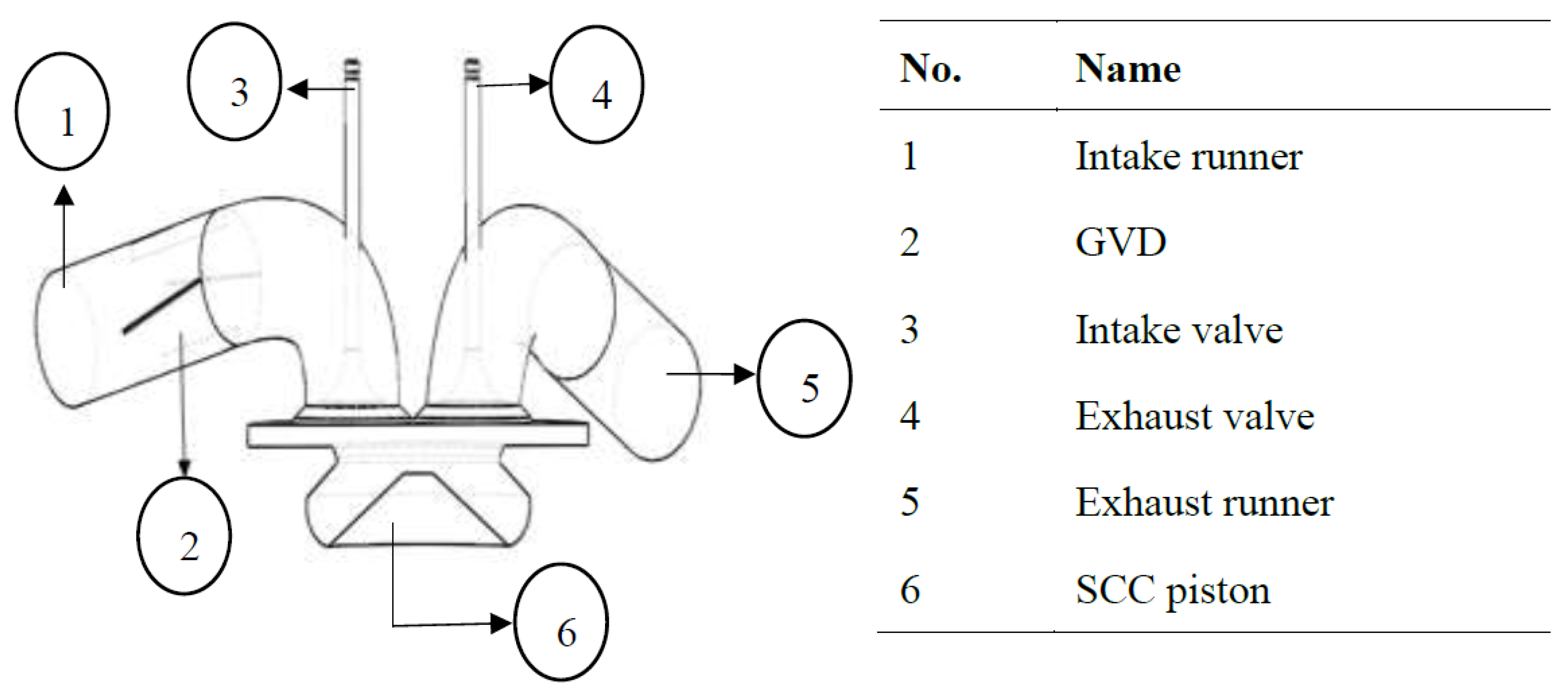
2.1. Engine Specification Model

The numerical investigation was conducted on the CI engine, which was readily available in the automotive laboratory of the School of Mechanical Engineering, Universiti Sains Malaysia. The engine was a Yanmar L70AE, which can constantly run at 2000 rpm. Table 1 shows the specifications of the Yanmar L70AE engine.

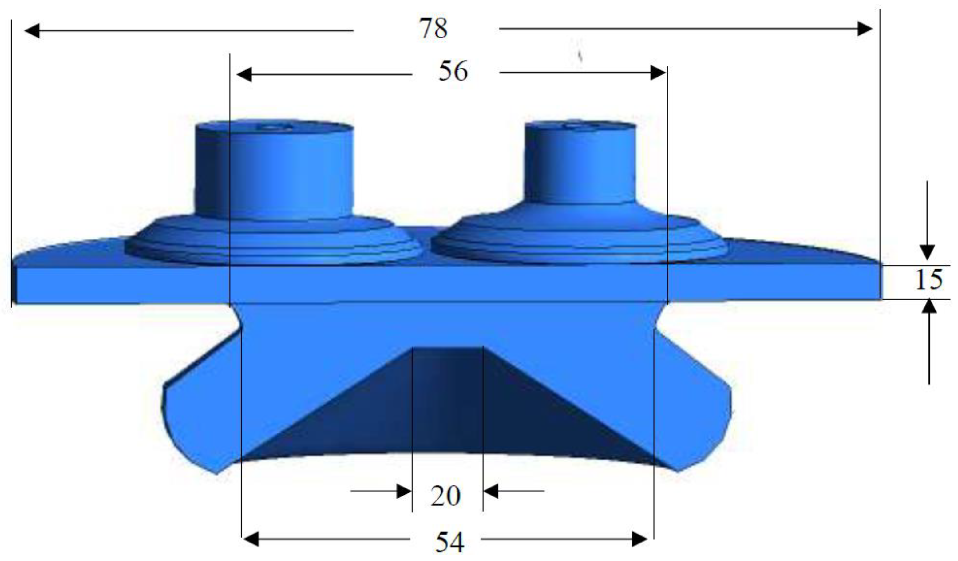
2.2. Design Geometry of Piston-Bowl

The selection of the piston-bowl geometry design is crucial because a very close relationship exists between the air–fuel mixture and emission formation in a diesel engine. The piston–bowl design employed in this study was the shallow depth re-entrance combustion chamber (SCC). The SCC piston-bowl design was chosen as it was capable of producing homogenous and well-organized in-cylinder airflow characteristics applicable for high viscosity fuels such as emulsified biofuel [27]. Figure 1 illustrates the SCC piston–bowl design.

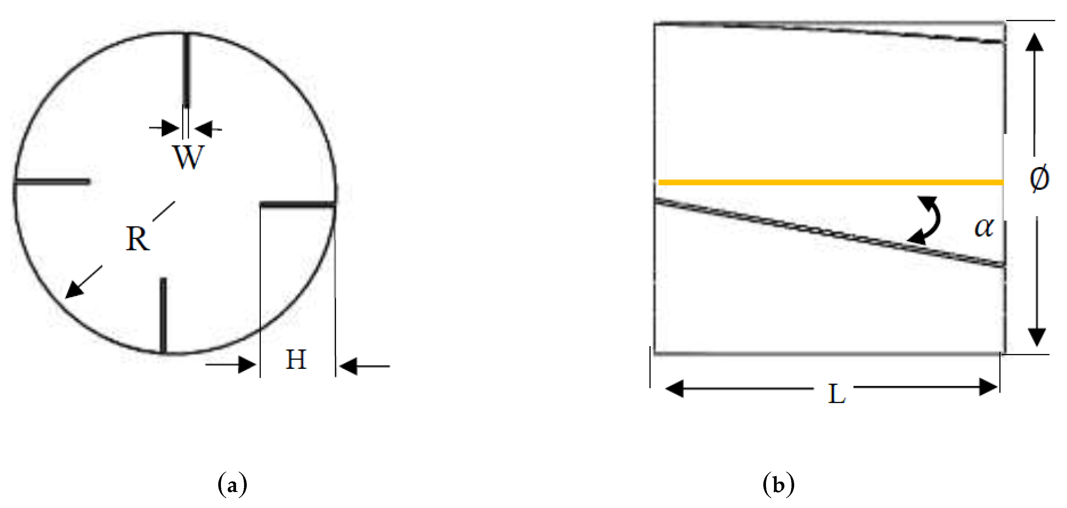
2.3. Guide Vane Design (GVD)

The primary purpose of a guide vane in the intake runner is to guide the airflow before it enters into the cylinder. It is a static vane used according to its shape to deflect the airflow [25]. It is usually placed within the intake system between the air filter and the inlet valve. In the existing engine, using alternative fuel of higher fuel viscosity will result in inferior engine performance due to the higher viscosity fuel. The pattern of spraying is also different when using diesel and alternative fuels like emulsified biofuel. The injection pattern when using diesel produced a wide cone angle and short-length penetration. However, using emulsified biofuel shows an inverse pattern of injection, which produces a low cone angle and long-length of penetration, promoting problems like carbon deposition in the piston bowl. In order to mitigate this limitation, the in-cylinder airflow characteristics need to be improved. The engine performance is enhanced by using alternative fuels or fuels with a higher viscosity, and it is necessary to improve the in-cylinder air flow swirl and tumble in the CI engine, i.e., at the start of injection (SOI), start of combustion (SOC) or in the ignition delay region. Attention is paid to the ignition delay because of the in-cylinder air flow strength, which is capable of breaking down the higher viscosity of the alternative fuel or emulsified biofuel molecules allowing them to spread outward and facilitating better mixing of air and fuel. Guide vane design considers the arrangement of vanes in the intake runner; the vanes serve to guide the airflow before the airflow is introduced into the combustion chamber during the intake stroke [26]. Since guide vanes have fins to guide the airflow, the developed swirl is predicted to be better than that produced by a typical engine configuration, as it will combine with the existing swirl created by the piston-bowl and swirl chamber.
The computer-aided design software, SolidWorks 2018, was utilized for drawing the guide vane model and for describing the study parameters. Limited literature is available concerning the effects of parameters such as the number of vanes, vane height and length, and their corresponding angles. The effect of guide vane length was investigated in this research, and the specifications of the GVD are given in Table 2. Based on studies found in the literature, the length of the guide vane is a key factor for determining the momentum and structure of the inlet airflow during a combustion process. However, an over-designed GVD length could result in hindering the airflow, which negatively affects the volumetric efficiency. In this sense, the current research varied this key parameter, i.e., GVD length, based on the diameter of the intake runner (R). The lengths were varied from 0.6 to 3.0 times the diameter (D) in steps of 0.6 and were labelled as 0.6D (L), 1.2D (L), 1.8D (L), 2.4D (L), and 3.0D (L), respectively. Altogether, a total of 5 GVD models with varying vane lengths were evaluated in this study. L represents the vane length, with variations, while the other parameters such as the angle, width, and number were correspondingly fixed at 35°, 0.2 times R, and four vanes were retained perpendicular to one another. Figure 2 shows the GVD design employed in this study.

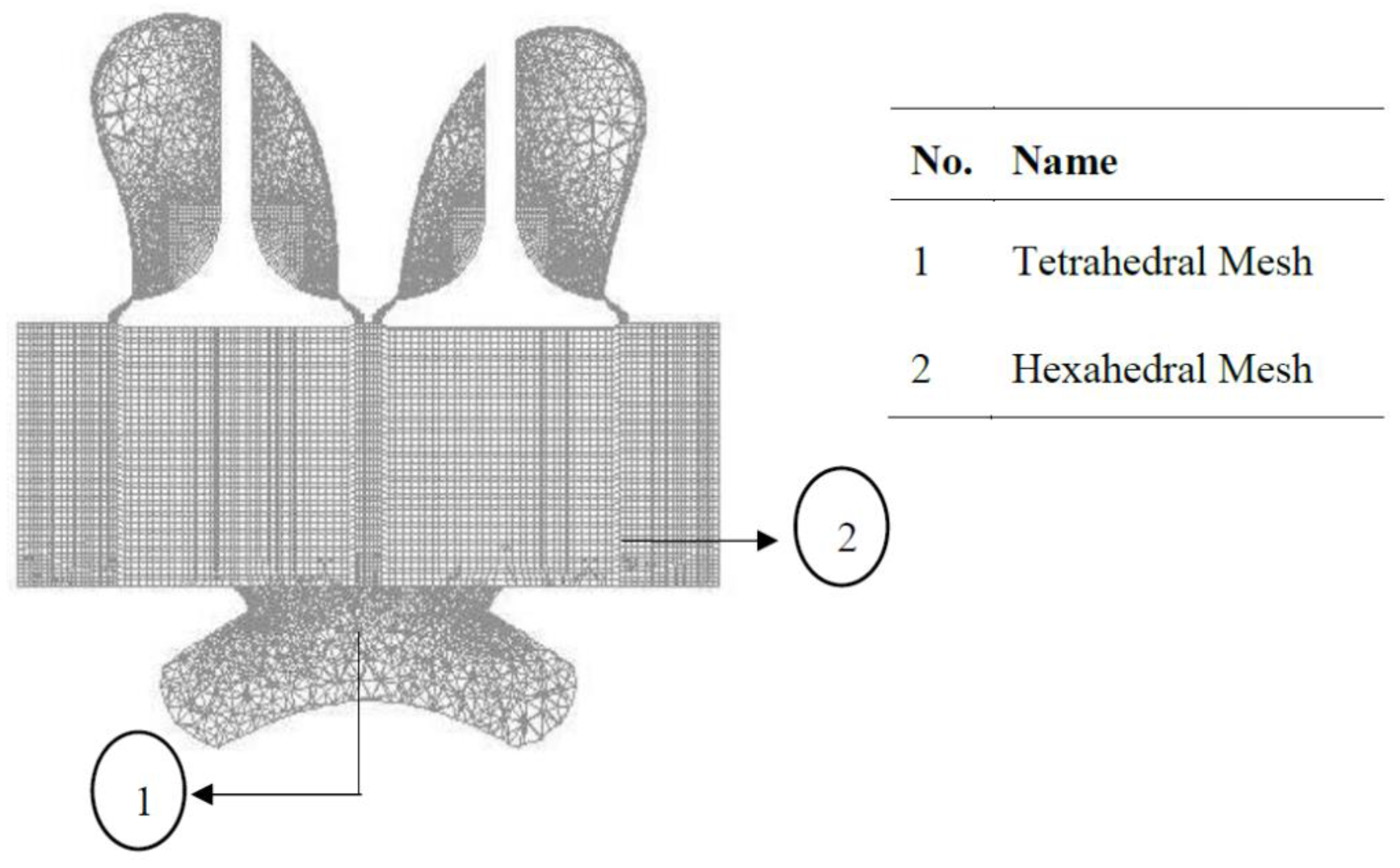
3. Numerical Setting

SolidWorks 2018 software was used to design the geometry of the YANMAR L70AE CI generator diesel engine, based on its specifications. The intake runner, intake valve, exhaust runner, and GVD were drawn separately as individual parts and were assembled as a single model, as shown in Figure 3. The complete assembled YANMAR L70AE CI generator diesel engine model was then exported to the ANSYS-FLUENT v15 CFD software to numerically investigate and solve the complex CFD model in a cost- and time-effective manner. ANSYS-FLUENT v15 software equipped with adaptive mesh refinery (AMR) was even capable of refining the mesh during piston motion from the bottom dead center (BDC) to the top dead center (TDC), as shown in Figure 4. In order to compute and analyze the parameters representing fluid flow, the overall engine body compartments were set as a fluid domain, except for the valves, which were set as a solid domain. However, the main challenge in the 3D simulation of the piston-bowl, valves, and cylinder of the CI engine was the correct handling of the moving boundaries, set for dynamic simulation. The strategies of mesh remapping and grid moving are the conventional techniques used by various researchers [30,31]. The mesh generation technique employed in this research was based on the level assembly meshing technique. The CFD simulation setting was based on the cold flow CI engine specifications published by the company ANSYS Inc. [32].
The numerical simulation presented in this work focused on the intake and compression strokes, using the algorithms of mesh simplification and dynamic mesh moving boundaries [32]. An arbitrary Lagrangian-Eulerian (ALE) approach was taken to treat the moving mesh for the typical events that occurred in the CI engine, encompassing the valve and piston motions. Every event represents different mesh types and boundary geometries for every single different step of crank angle. Therefore, to perform a proper numerical simulation for the CI engine, several analyses and calculations should be considered, including the unsteady flow (transient) condition, high compressible Reynolds number (Re), moving mesh, momentum, heat, and mass transfer computations.
The conservation of mass, momentum, energy (energy equations) and k-ɛ turbulence models are governed by the Navier-Stokes equations [33], given below:
ρ t + . ( ρ U ) = 0
where ρ is the density of the fluid and U is the three-dimensional speed in the direction of the x, y and z axes. The momentum equation is based on Newton’s second law of motion, in which the forces considered are the body and the surface forces on the volume of control, written as follows:
( ρ U ) t + . ( ρ U U ) = p + . τ + S M
where p is the pressure of the fluid, τ is the strain rate and S M is a source of momentum. All of these equations are referred to as Navier-Stoke equations [33]. The energy equation is defined as the rate of energy change within the fluid element, given in the conservation form by
( ρ h t o t ) t ρ t + . ( ρ U h t o t ) = . ( λ T ) + . ( U . τ ) + U . S M
where h t o t is total enthalpy and λ is thermal conductivity, respectively.
Shear stress transport (SST) is a two-equation eddy–viscosity model that is employed in this analysis. The SST model is a combination of k-ω and k-ɛ turbulence models which can overcome the limitation of the shear stress until a 5% turbulence intensity is reached in the adverse gradient region. The pressure and temperature conditions considered in this study are 101.3 kPa and 300 K, respectively. Detailed information on the settings and boundary conditions of the models can be referred to in the ANSYS FLUENT v15-Solver Theory Guide [32].
On the theoretical basis of physical boundary conditions of the engine, two distinct phases of simulation studies were carried out: intake port analysis and intake analysis. Intake port analysis is associated with the clearance volume before airflow is inducted into the cylinder along the y-direction, while the intake analysis is related to the intake runner. The components that are not applicable in this work were suppressed as there was no contribution to the results. This is to minimize the computation time and increase the accuracy of analysis during the calculations.

4. Results and Discussion

The use of high viscosity fuels like emulsified biofuel aimed to improve the engine’s performance, reduce the emissions, and increase the engine lifespan. Therefore, this research focuses on improving the characteristics of in-cylinder airflow to stimulate diffusion, evaporation, air-fuel mixing, and combustion processes in the CI engine, within the injection delay period. Based on the specifications of the Yanmar L70 engine as shown in Table 1, the injection timing was set 14° before approaching the top dead center (BTDC). Thus, this section also presents the in-cylinder airflow characteristics concentrating on the start of injection (SOI) between the crank angle (CA) of 346° and the start of combustion (SOC) between 352° CA. The in-cylinder airflow characteristics, such as swirl (Rs), turbulence kinetic energy (TKE), tumble (RT), and cross tumble ratio (RCT) are the determining components responsible for stimulating diffusion, evaporation and mixing, thereby improving the combustion efficiency. Hence, the simulation results were compared for various vane lengths with the base model of the engine to examine the effects on the in-cylinder airflow characteristics and eventually determine the optimum vane length.

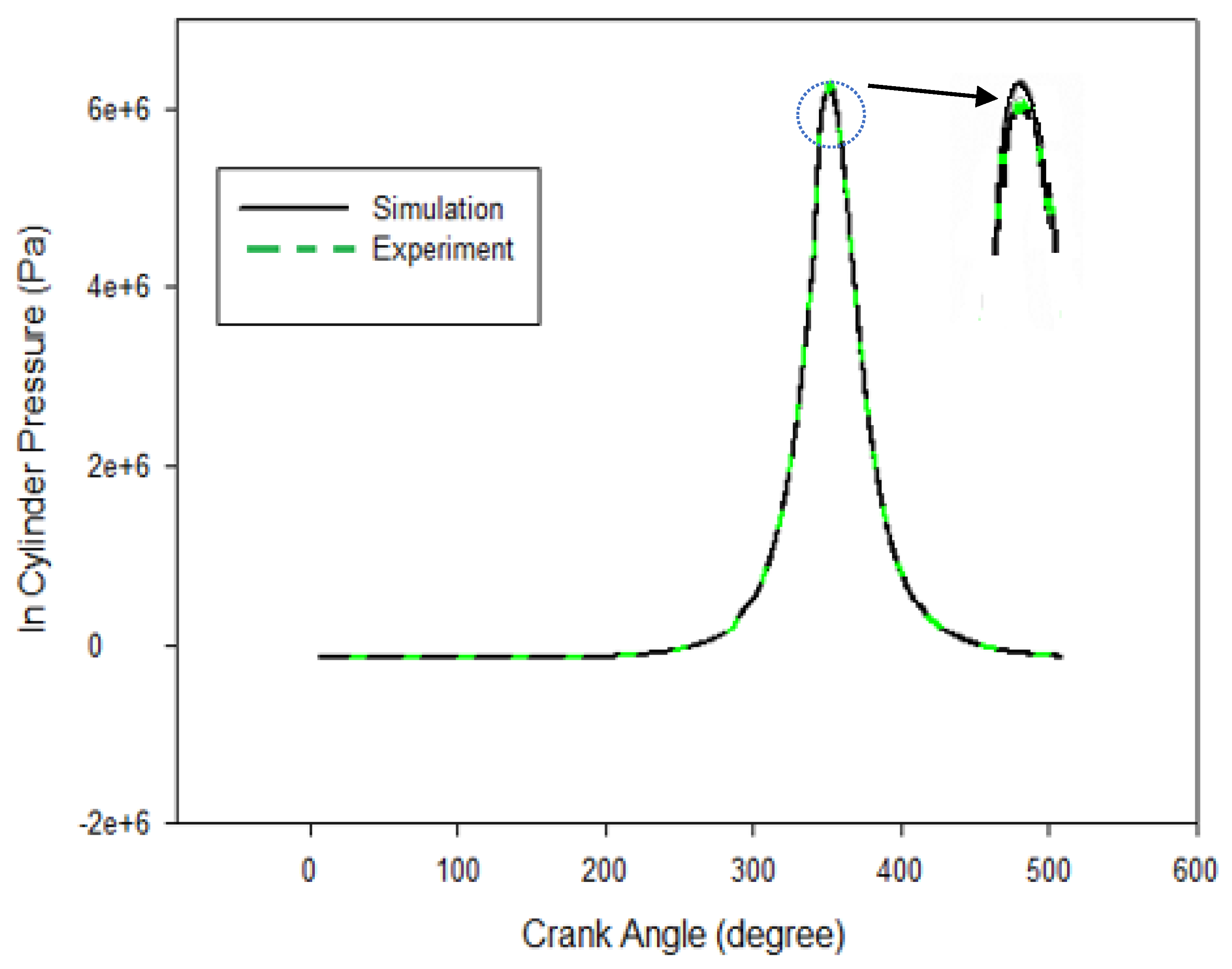
4.1. Model Validation

This section discusses the experimental setup adopted in the study for validating the results of numerical simulation. The experiment was carried out in a test rig of the CI generator diesel engine YANMAR L70AE model, as shown in Figure 5. The existing data were used for numerical validation, considering some important technical aspects. During the experiment, all the engine boundary conditions were fixed, and a Kistler 7061B sensor with a highly sensitive water-cooled precision was screwed directly into the standard M14 hole. An optical sensor at the TDC position with a magnetic pickup shaft encoder was used to measure the in-cylinder pressure and record the data of crank angle positions. For better accuracy, the sensor was mounted near the valve. K-type thermocouples were installed at the intake and exhaust boundaries as close as possible to the cylinder head to measure the temperature. In this experiment, the SCC piston was fabricated and installed first-hand in the YANMAR L70AE CI generator diesel engine before running the engine test rig to collect experimental data.
In order to characterize the large scale in-cylinder air-fuel mixing during the intake and compression strokes, three main components that influence the in-cylinder air flow motion, namely Rs, RT and RCT were calculated based on the crank angle engine stroke. Figure 6 shows the swirl, tumble and cross tumble ratio orientation diagrams acting on the cylinder. The dimensionless parameter used to quantify the rotational and angular motion inside the cylinder commonly characterized the swirl, tumble and cross tumble ratio. These values were calculated by dividing the engine speed by the effective angular velocity of the in-cylinder air motion. The three variables investigated in this paper (swirl, tumble and cross tumble ratio) are presented in non-dimensionless equations [32], as follows:
Swirl ratio is defined as:
R s   =   60 H z 2 π I z ω
Tumble ratio is defined as:
R T   =   60 H x 2 π I x ω
Cross tumble is defined as:
R C T   =   60 H y 2 π I y ω
where Hx, Hy, and Hz represent the angular momentum of the cylinder gas about the x-axis, y-axis and z-axis, respectively. The symbol Ω represents the crankshaft rotation or engine speed in the unit of rotation/minutes.
Figure 7 illustrates the in-cylinder pressure (Pa) against the crank angle (θ) for both the experimental and numerical results of the engine operation without combustion at a rotational speed of 2000 rpm for the intake temperature and pressure of 302 K and 102 kPa, respectively. The numerical data collected with the GVD consist of intake, compression, and expansion stroke between 0° to 540°. Based on the results, a good agreement between numerical and experimental results with a slight difference of about 7% at the peak pressure was observed. This might be due to the friction loss that occurred inside the cylinder while running the experiment, a factor which is not possible to include in simulation through numerical analysis.

4.2. Grid Independence Test (GIT)

A grid independence test (GIT) is a term used to describe the process of improving the results by successfully using smaller cell sizes for the calculations. A calculation should approach the correct answer as the mesh gets finer. The components involved in the numerical calculations are the valves, intake port, cylinder head and piston-bowl. GIT is essentially performed as it will affect the time and cost of the computational analysis. Typically, the cell size ranges from coarse to ultrafine, and the number of elements was set between 100 and 400 k. For the sake of grid sensitivity and reasonable computation time, half of the cells were used to generate meshes in the cylinder head and piston-bowl. The hexahedral mesh was applied in the mesh generation step at the cylinder motion from the bottom dead center (BDC) to top dead center (TDC), owing to their stability and better accuracy compared to other types of mesh. Table 3 shows the comparison of elements average cylinder of mesh and the pressure generated into the cylinder. From Table 3, Case 3 exhibits the optimum pressure generated; when the elements of the mesh were increased, the pressure indicated similar values to Case 3. Therefore, Case 3 was selected for further analysis.

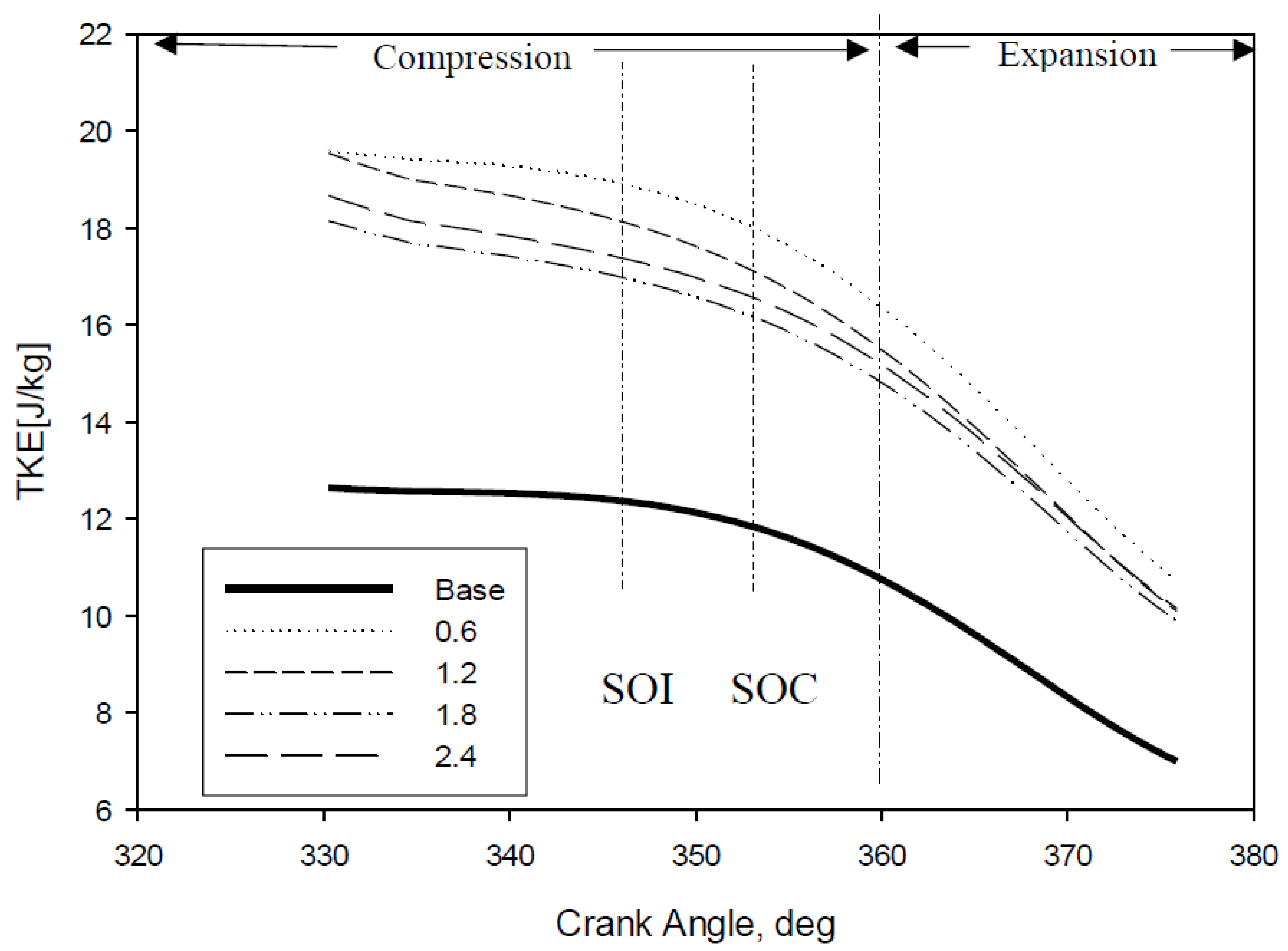
4.3. Turbulence Kinetic Energy (TKE)

Theoretically, TKE is the mean kinetic energy per unit mass associated with eddies in a turbulent flow [3,34]. In other terms, it is the fluctuation of velocity in the in-cylinder airflow and is calculated based on the root-mean-square. During the movement of the piston in the compression stroke, the piston moves from the bottom dead centre (BDC) towards the top dead centre (TDC) and reduces the volume of the combustion chamber, hence limiting the fluctuation of the cylinder airflow motion. When the piston approaches the TDC, the velocity of air starts to decrease and becomes zero after reaching the TDC. Therefore, TKE is expected to decrease during this time. Several researchers studied and confirmed that the trend of turbulence pattern diminished linearly while the piston was heading towards the TDC [35,36]. Furthermore, Payri et al. investigated and found that in the early stage of the intake stroke, the piston geometry had little effect on the in-cylinder airflow [35]. However, the piston-bowl geometry played a significant role during the movement of the piston approaching the TDC in the compression stroke and the early stage of the expansion stroke. Figure 8 demonstrates that the base engine without GVD showed the lowest magnitude of TKE compared to the other modifications of GVD. The TKE of the vane modified engine compared with the baseline engine showed a 30% difference with 1.8D (L), 35% with 2.4D (L), 40% with 1.2D (L), and 45% with 0.6D (L).
The GVD model with 0.6D (L) displayed the highest TKE produced, followed by the other designs. The graph also implies that further increase in the length of the GVD does not considerably increase the TKE. However, it could be an indication of the minimal length of GVD required for rapid guidance of airflow, less air resistance, and swift initial turbulence in the intake manifold. A minimal length of vanes would be able to guide the airflow while the SCC piston produced a higher magnitude of TKE. The swirl, which already existed in the SCC piston-bowl and the extra swirl created via the 0.6D (L) GVD, could match the wind and create a larger magnitude of total swirl. Based on the result, the GVD successfully improved and increased the average magnitude of TKE.

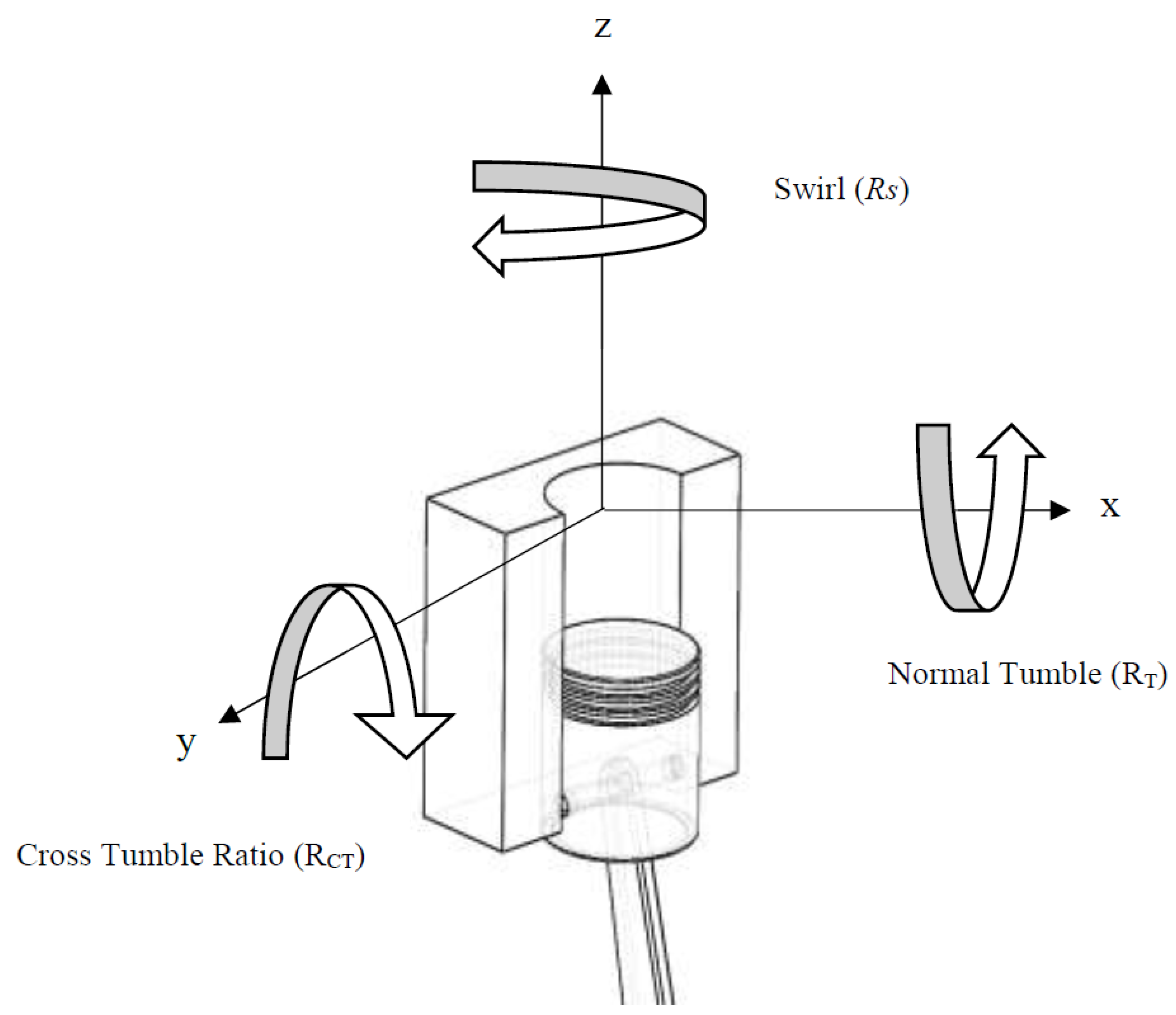
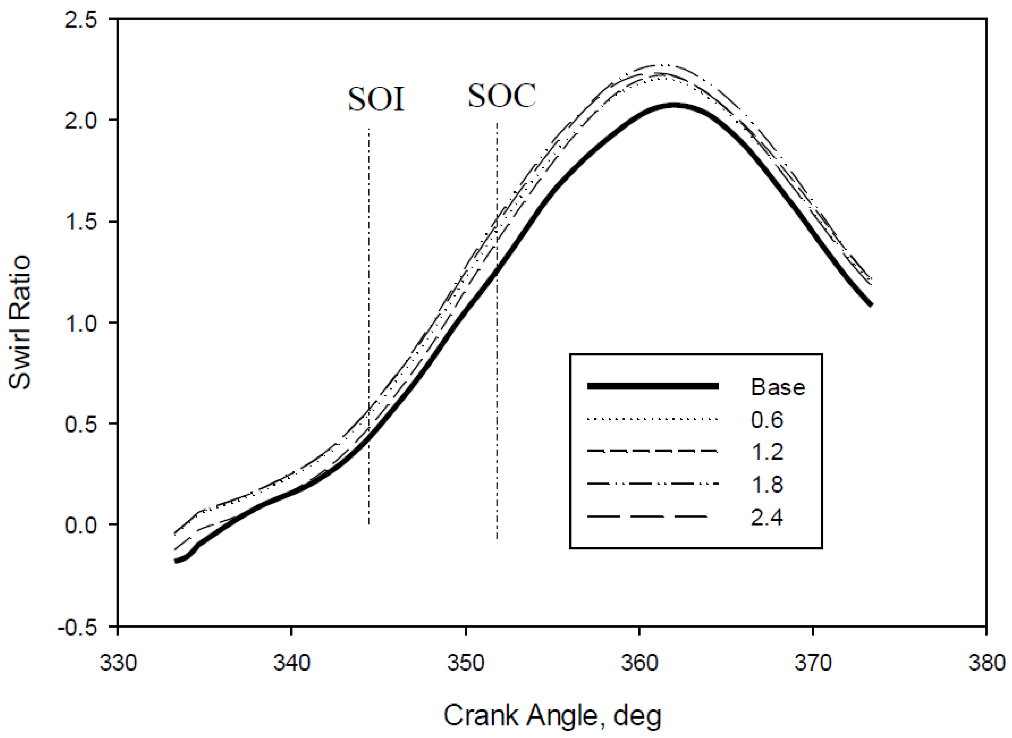
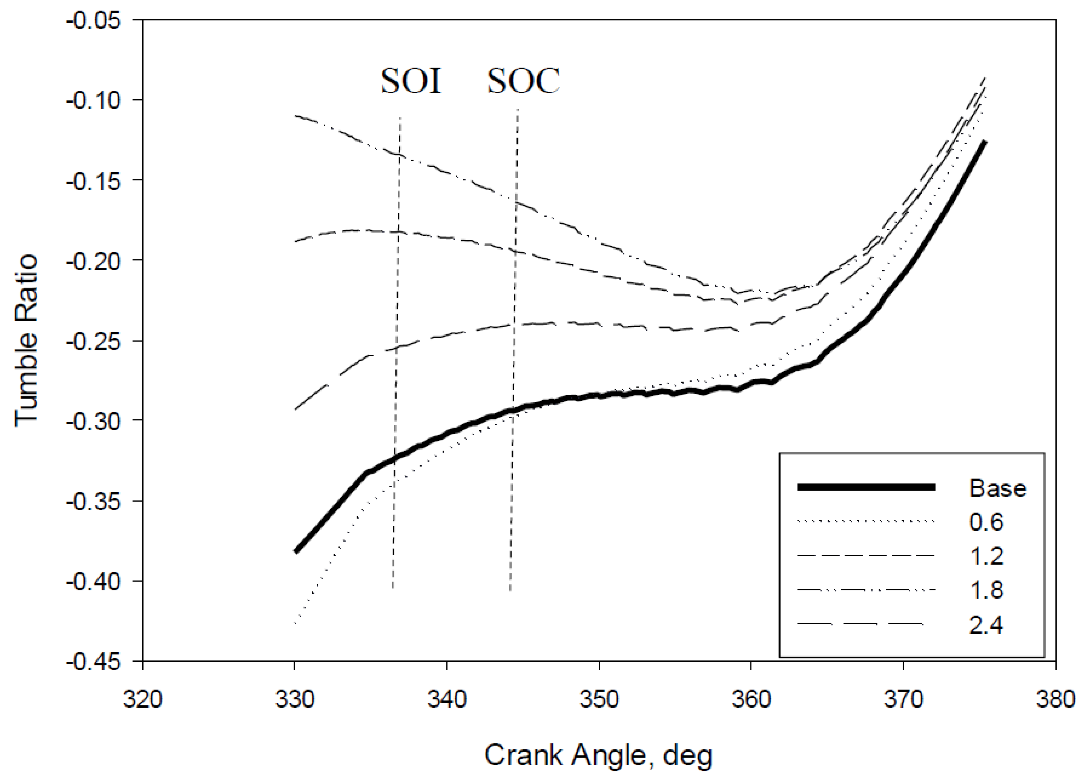
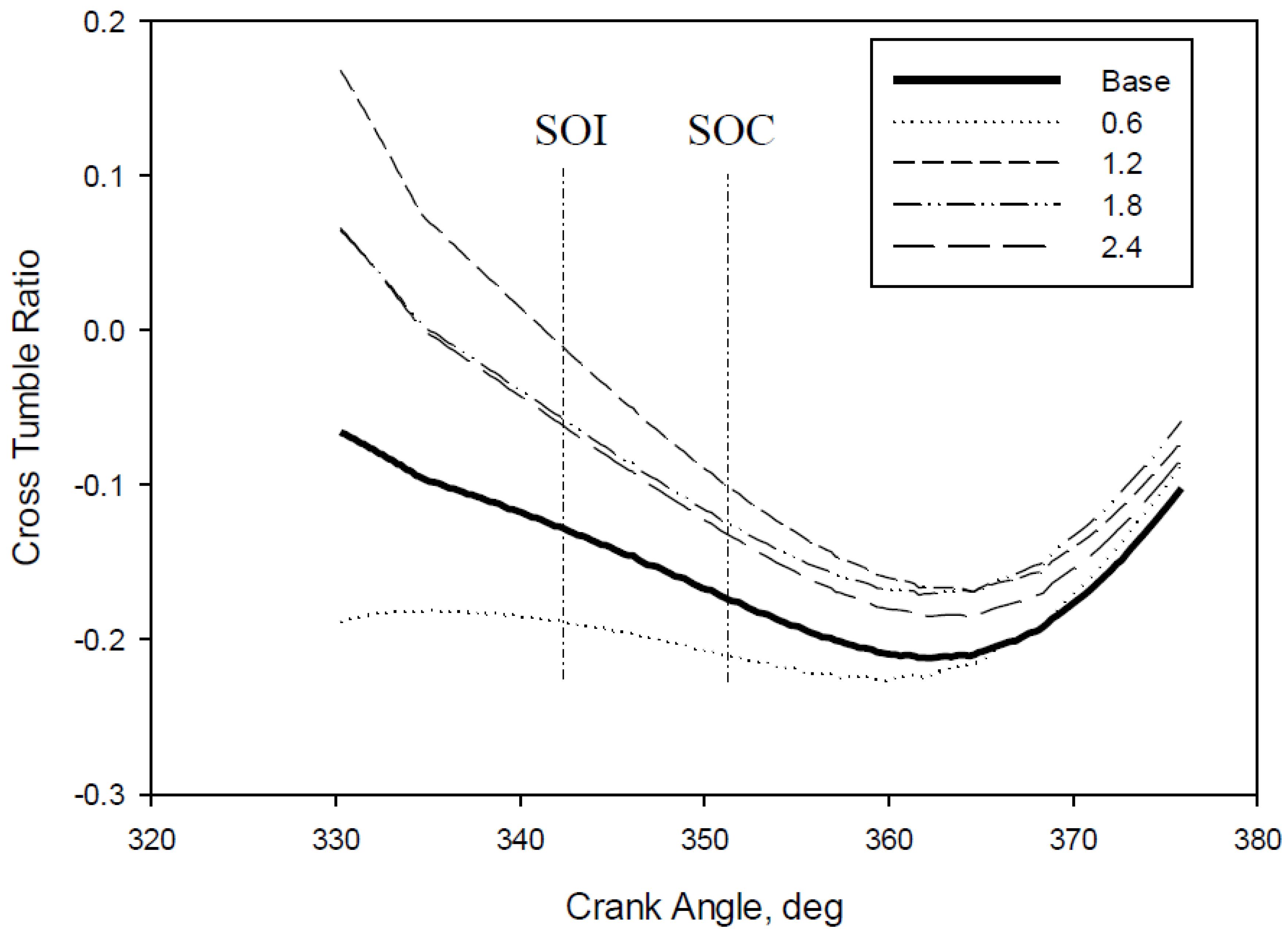
4.4. In-Cylinder Swirl (Rs), Tumble (RT), and Cross Tumble Ratio (RCT)

The in-cylinder airflow motion in the combustion chamber is an important factor that will determine the scale of air and fuel mixing during the intake and compression stroke, particularly in the velocity streamline. The three main components of air structure that will influence the combustion efficiency are RS, RT, and RCT. Figure 9 shows the in-cylinder air flow swirling strength (Rs) of the local swirling motion. Rs is defined by the organized movement of fresh air around the cylinder axis. Swirl is created by an initial angular momentum of the intake airflow into the cylinder. In a diesel engine, the swirl ratio is important for the preparation of the air-fuel mixture. The swirl effect can be induced by a special intake port(s) shapes created by the rotational flow in the intake valve area transferred to the cylinder during the intake process [37]. The simulation results for various vane lengths are illustrated in Figure 9, which shows the magnitude of Rs. Based on Figure 9, it is found that all the variations of the GVD model witness an improvement in the Rs compared to the base model. In combustion theory, the generation of swirl inside the combustion chamber during the injection period assists in breaking down the molecular chain and practically improves the mixing process of air and fuel, thereby ultimately improving the combustion and engine efficiency [38]. The GVD design of 0.6D (L) represents the optimum guide vane length to enhance Rs produced during the start of injection (SOI) and the start of combustion (SOC).
Figure 10 illustrates the behavior of RT for different lengths of GVD against the crank angle before approaching the TDC. RT is defined as the ratio between the equivalent angular velocity of the instant solid body and the angular velocity of the engine. The angular velocity (ω) is the angular velocity of a rotating solid angular momentum body equal to that of the instantaneous in-cylinder mass, evaluated perpendicular to the cylinder axis and centered between the head and the instantaneous piston position [39]. The negative or positive sign of RT is neglected as it is arbitrary and dependent on the magnitude obtained. From the graph, it can be seen that the design of the GVD type 0.6D (L) produced a value closer to that of the base model. However, the GVD model of 0.6D (L) showed a slightly higher RT value magnitude, about 7% different from that of the baseline engine in the area of the start of injection (SOI). The other GVD designs showed a lower magnitude of RT values compared to the baseline engine. This implies that GVD is capable of generating a strong lateral airflow within the cylinder. Strong lateral airflow generated in the cylinder is imperative and will aid in enhancing the speed and spread of the atomization of the fuel during the injection. As a result, an improvement in the flame propagation and combustion efficiency is observed while eliminating the carbon deposition that will reduce the lifespan of the engine.
Figure 11 shows the RCT for the different lengths of GVD against the crank angle before approaching the TDC. RCT is defined as the rotational ratio of airflow on the cross tumble axes [40]. In combustion theory, the enhancement of RCT facilitates the increment of turbulent flow and assists in homogenous mixing of the fuel and air along the piston-bowl. Nevertheless, RCT has a close correlation with Rs and RT. Bari et al. found that in order to improve RCT in a CI engine, Rs and RT values need to be improved [41,42]. Prasad et al. reported that enhancing the RCT air motion is a crucial issue, as it has an impact on increasing the air-fuel mixing process, achieving faster burning rates, increasing indicated efficiency, and improving the air management [43]. As previously mentioned, the use of higher viscosity fuels such as emulsified biofuel will deteriorate the atomization process, subsequently decreasing the cone angle and increasing the length of penetration. Hence, with the correct length of GVD, RCT would be able to significantly break down the length of penetration, which is expected to widen the cone angle during the injection period. Based on the figure, the 0.6D (L) GVD shows the highest magnitude of values compared to the base engine and other models of GVD. It is noticeable that the 0.6D (L) GVD can produce a homogeneous mixture during compression and consequently improves the lateral flow of air within the cylinder.

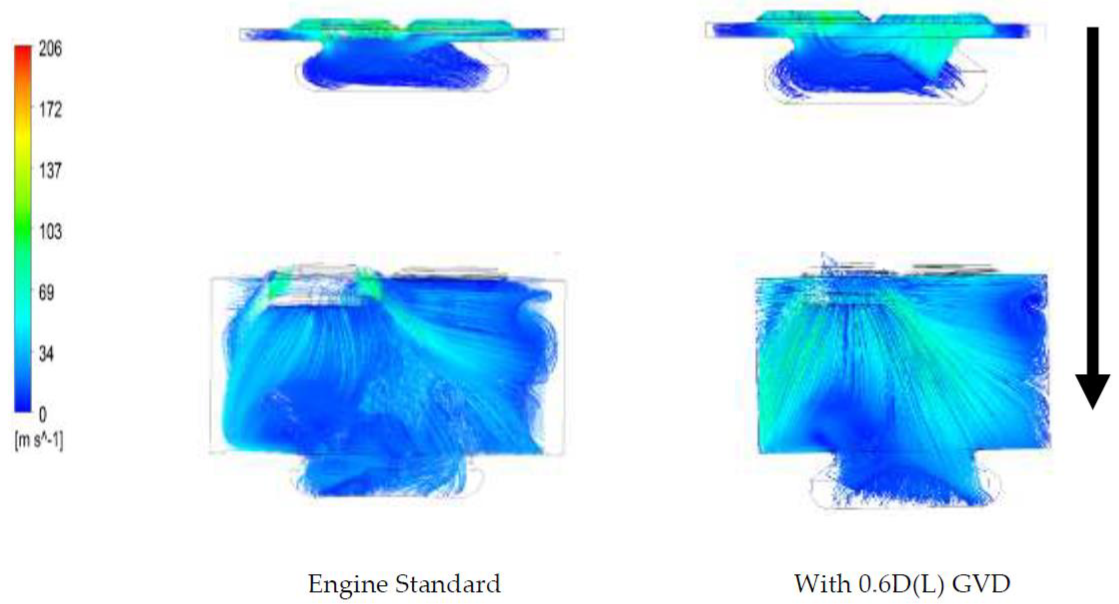
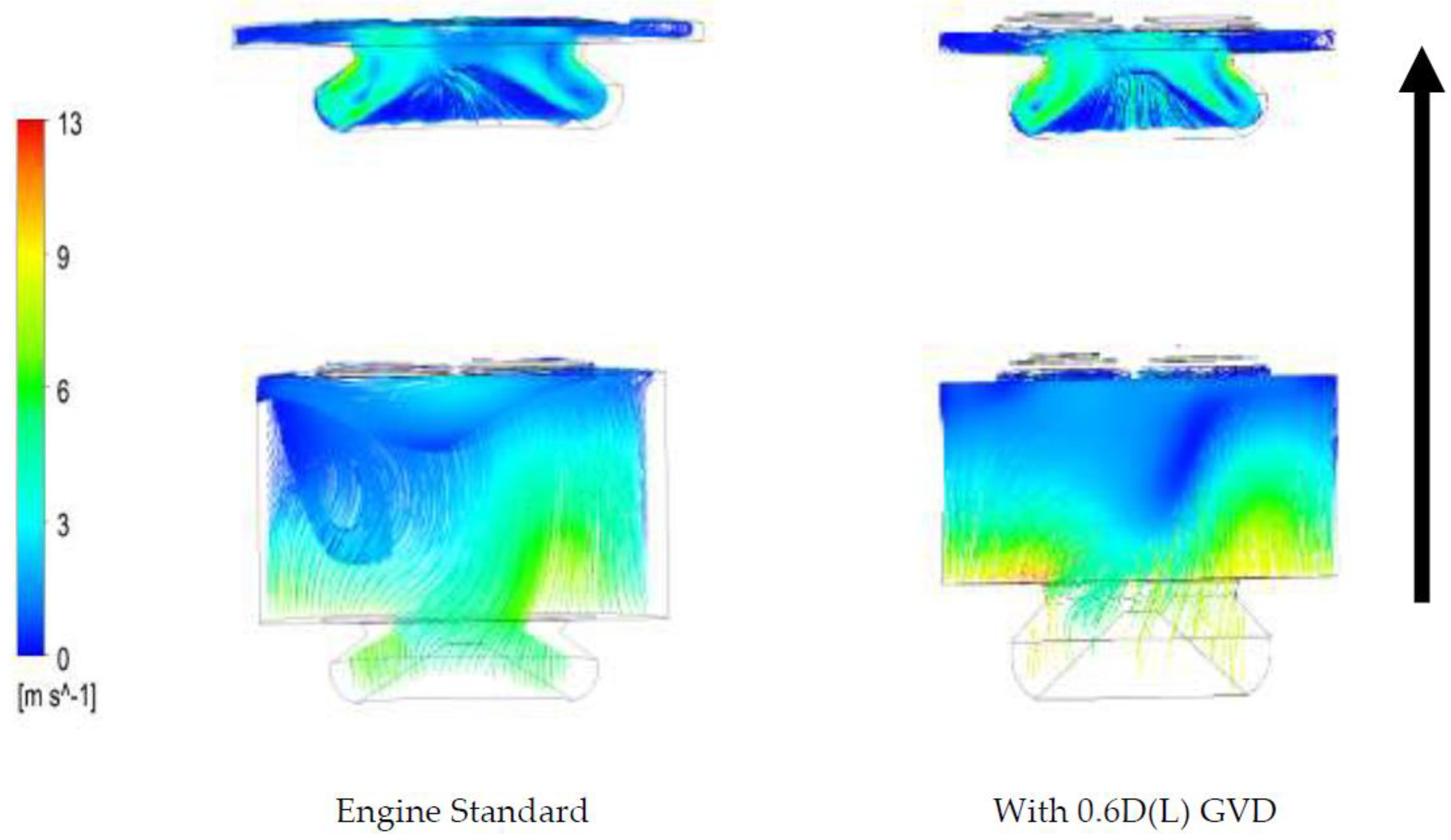
4.5. Characteristics of Cylinder Airflow During Intake and Compression Stroke

Figure 12 illustrates the intake stroke of the streamline of 10° and 100° crank angle (CA). During the intake stroke at 10° CA, the airflow was initially induced through the SCC piston. As a result of the lack of guidance in the intake stroke, tumbled flow occurred when the intake valve was opened. However, when considering the 0.6D (L) GVD, the in-cylinder air flow phenomena behaved differently. When the intake valve was opened, the airflow initially produced swirl. From the graph, it can also be seen that in-cylinder airflow velocity improved when using the GVD compared to that of the standard engine. This outcome is crucial to enhance the in-cylinder airflow by promoting the atomization of heavy molecules, like emulsified biofuels. The engine that does not use vanes showed lower air velocity in the combustion chamber during the intake stroke. These results were supported by studies of Heywood [44], where it was recommended that turbulence intensity in the combustion chamber could be increased by improving the vortex flow during the intake stroke.
Figure 13 illustrates the compression stroke of the streamline of 350° and 310° CA. In the compression stroke, the piston starts to compress while moving from the BDC to the TDC, and the volume in the combustion chamber begins to decrease due to the motion of the piston. When both the intake valve and the exhaust valves are closed, air density, temperature and pressure witness an increase. Figure 13 shows that the velocity of air is higher during the compression stroke of 310° and begins to decrease when the piston approaches the TDC. The combination of the SCC piston and the GVD successfully improves the uniformity of airflow on both the sides and also increases the velocity of air throughout the SCC piston compared to the engine standards. It implies that the engine which uses vanes in its operation produces higher velocity airflow, high turbulent flow and is able to transport heavy fuel molecules.

5. Conclusions

Alternative fuels, particularly emulsified biofuel, possess high potential to replace conventional diesel fuels in the near future. The renewable nature and the similarities in the chemical properties of the emulsified fuel show that the existing YANMAR L70AE CI generator diesel engine can use these alternative fuels with minor modifications. However, high viscosity fuels are generally characterized by low volatility, comprised of heavier molecules of fuel which may result in a longer length of penetration and shorter cone angles during injection in the combustion chamber. These patterns of injection result in incomplete combustion and carbon deposition in the cylinder wall and piston head. The combination of the GVD and SCC piston-bowl design has successfully enhanced the in-cylinder airflow characteristics as well as those of Rs, RT, RCT, and TKE in order to assist in evaporating higher viscosity fuel to improve the combustion and reduce the carbon deposition. ANSYS FLUENT V15 was used to run the simulation, and it was found that most of the results showed that the 0.6D (L) GVD design incorporated with SCC piston was capable of improving the in-cylinder airflow characteristics with better-organized airflow during SOI to SOC period (injection delay) compared to the baseline engine (without GVD). This combination of improved characteristics of the in-cylinder airflow is expected to effectively break the penetration length of highly viscous fuels and increase the volatility of the alternative fuels, resulting in better combustion and reduced carbon deposits. Therefore, it can be concluded that installing the 0.6D (L) GVD incorporated with the SCC piston will enhance the in-cylinder airflow characteristics and subsequently improve the performance of engine running on high viscosity fuels. In the future, the study will be extended to investigate the effect on the injection profile, structure of spraying, and the combustion characteristics based on the combination of the GVD incorporated with SCC piston in diesel engines.

Author Contributions

Conceptualization, M.F.H. and M.Y.I.; Methodology, M.F.H., M.K.A., M.Y.I. and S.S.; Experimentation, S.C.M., M.F.H. and T.Y.H.; Data analysis, M.F.H., M.M. and M.A.M.; Resources, M.Y.I., M.F.H. and M.A.M.; Writing—original draft preparation, M.F.H. and M.K.A.; Writing, review and editing: Z.A.Z.A. All authors have read and agreed to the published version of the manuscript.

Funding

The authors would like to thank Universiti Sains Malaysia (USM) for providing financial support through the Research University Grant Scheme under Grant No. 1001/PBAHAN/8014006 and USM Fellowship RU (1001/CIPS/AUPE001).

Conflicts of Interest

The authors declare no conflict of interest.

Nomenclature

English SymbolDescriptionUnit
U Three-dimensional flow velocities in the x, y, and z directionsm/s
PPressurePa
𝚝Times
h Total enthalpyJ/kg
S M Momentum sourceN/m3
RRadiusmm
lLengthmm
x,y,zCartesian coordinatesmm
Greek SymbolDescriptionUnit
𝜌Fluid densitykg/m3
ωAngular acceleration rad/s
λThermal conductivityW/m.K
θCrank angle degree
𝜏Strain rate1/s
α Vane twist angle
Gradient operator
AbbreviationDescription
GVDGuide vane design
HVFHigher viscosity fuel
SCCShallow depth re-entrance combustion chamber
SMMomentum source
RTTumble ratio
SOIStart of Injection
SOCStart of Combustion
RSSwirl ratio
CICompression Ignition
JMEJatropha methyl ester
HCHydrocarbons
CACrank Angle
RCTCross tumble ratio
TKETurbulence kinetic energy

References

  1. Mahmudul, H.M.; Hagos, F.Y.; Mamat, R.; Adam, A.A.; Ishak, W.F.W.; Alenezi, R. Production, characterization and performance of biodiesel as an alternative fuel in diesel engines—A review. Renew. Sustain. Energy Rev. 2017, 72, 497–509. [Google Scholar] [CrossRef]
  2. Sivaganesan, S.; Chandrasekaran, M. Impact of various compression ratio on the compression ignition engine with diesel and mahua biodiesel. Int. J. ChemTech Res. 2016, 9, 63–70. [Google Scholar]
  3. Hamid, M.F.; Idroas, M.Y.; Basha, M.H.; Sa’ad, S.; Che Mat, S.; Abdullah, M.K.; Zainal Alauddin, Z.A. Numerical study on dissimilar guide vane design with SCC piston for air and emulsified biofuel mixing improvement. MATEC Web Conf. 2016, 90, 01065. [Google Scholar] [CrossRef] [Green Version]
  4. International Energy Agency. World Energy Outlook Special Report: Energy and Climate Change; International Energy Agency: Paris, France, 15 June 2015. [Google Scholar]
  5. Popp, J.; Lakner, Z.; Harangi-Rákos, M.; Fári, M. The effect of bioenergy expansion: Food, energy, and environment. Renew. Sustain. Energy Rev. 2014, 32, 559–578. [Google Scholar] [CrossRef] [Green Version]
  6. Azad, A.K.; Rasul, M.G.; Khan, M.M.K.; Sharma, S.C.; Hazrat, M.A. Prospect of biofuels as an alternative transport fuel in Australia. Renew. Sustain. Energy Rev. 2015, 43, 331–351. [Google Scholar] [CrossRef]
  7. Nalgundwar, A.; Paul, B.; Sharma, S.K. Comparison of performance and emissions characteristics of di CI engine fueled with dual biodiesel blends of palm and jatropha. Fuel 2016, 173, 172–179. [Google Scholar] [CrossRef]
  8. Reham, S.S.; Masjuki, H.H.; Kalam, M.A.; Shancita, I.; Rizwanul Fattah, I.M.; Ruhul, A.M. Study on stability, fuel properties, engine combustion, performance and emission characteristics of biofuel emulsion. Renew. Sustain. Energy Rev. 2015, 52, 1566–1579. [Google Scholar] [CrossRef]
  9. Annamalai, M.; Dhinesh, B.; Nanthagopal, K.; SivaramaKrishnan, P.; Isaac JoshuaRamesh Lalvani, J.; Parthasarathy, M.; Annamalai, K. An assessment on performance, combustion and emission behavior of a diesel engine powered by ceria nanoparticle blended emulsified biofuel. Energy Convers. Manag. 2016, 123, 372–380. [Google Scholar] [CrossRef]
  10. Ayhan, V.; Tunca, S. Experimental investigation on using emulsified fuels with different biofuel additives in a DI diesel engine for performance and emissions. Appl. Therm. Eng. 2018, 129, 841–854. [Google Scholar] [CrossRef]
  11. Prakash, R.; Singh, R.K.; Murugan, S. Experimental studies on combustion, performance and emission characteristics of diesel engine using different biodiesel bio oil emulsions. J. Energy Inst. 2015, 88, 64–75. [Google Scholar] [CrossRef]
  12. Raheman, H.; Kumari, S. Combustion characteristics and emissions of a compression ignition engine using emulsified jatropha biodiesel blend. Biosyst. Eng. 2014, 123, 29–39. [Google Scholar] [CrossRef]
  13. Dhinesh, B.; Annamalai, M. A study on performance, combustion and emission behaviour of diesel engine powered by novel nano nerium oleander biofuel. J. Clean. Prod. 2018, 196, 74–83. [Google Scholar] [CrossRef]
  14. Che Mat, S.; Idroas, M.Y.; Hamid, M.F.; Zainal, Z.A. Performance and emissions of straight vegetable oils and its blends as a fuel in diesel engine: A review. Renew. Sustain. Energy Rev. 2018, 82, 808–823. [Google Scholar] [CrossRef]
  15. Ramesh, A.; Ashok, B.; Nanthagopal, K.; Ramesh Pathy, M.; Tambare, A.; Mali, P.; Phuke, P.; Patil, S.; Subbarao, R. Influence of hexanol as additive with Calophyllum Inophyllum biodiesel for CI engine applications. Fuel 2019, 249, 472–485. [Google Scholar] [CrossRef]
  16. Ashok, B.; Nantha Gopal, K.; Rajagopal, T.K.R.; Alagiasingam, S.; Appu, S.; Murugan, A. Design and analysis of a fuel preheating device for evaluation of ethanol based biofuel blends in a diesel engine application. SAE Int. J. Engines 2017, 10, 39–45. [Google Scholar] [CrossRef]
  17. Mofijur, M.; Rasul, M.G.; Hyde, J.; Azad, A.K.; Mamat, R.; Bhuiya, M.M.K. Role of biofuel and their binary (diesel-biodiesel) and ternary (ethanol-biodiesel-diesel) blends on internal combustion engines emission reduction. Renew. Sustain. Energy Rev. 2016, 53, 265–278. [Google Scholar] [CrossRef] [Green Version]
  18. Vallinayagam, R.; Vedharaj, S.; Yang, W.M.; Lee, P.S.; Chua, K.J.E.; Chou, S.K. Pine oil-biodiesel blends: A double biofuel strategy to completely eliminate the use of diesel in a diesel engine. Appl. Energy 2014, 130, 466–473. [Google Scholar] [CrossRef]
  19. Mat, S.C.; Idroas, M.Y.; Teoh, Y.H.; Hamid, M.F. Physicochemical, performance, combustion and emission characteristics of melaleuca cajuputi oil-refined palm oil hybrid biofuel blend. Energies 2018, 11, 3146. [Google Scholar] [CrossRef] [Green Version]
  20. Koc, A.B.; Abdullah, M. Performance and NOx emissions of a diesel engine fueled with biodiesel-diesel-water nanoemulsions. Fuel Process. Technol. 2013, 109, 70–77. [Google Scholar] [CrossRef]
  21. Tan, Y.H.; Abdullah, M.O.; Nolasco-Hipolito, C. The potential of waste cooking oil-based biodiesel using heterogeneous catalyst derived from various calcined eggshells coupled with an emulsification technique: A review on the emission reduction and engine performance. Renew. Sustain. Energy Rev. 2015, 47, 589–603. [Google Scholar] [CrossRef]
  22. Agarwal, A.K. Biofuels (alcohols and biodiesel) applications as fuels for internal combustion engines. Prog. Energy Combust. Sci. 2007, 33, 233–271. [Google Scholar] [CrossRef]
  23. Bari, S.; Saad, I. Performance and emissions of a compression ignition (CI) engine run with biodiesel using guide vanes at varied vane angles. Fuel 2015, 143, 217–228. [Google Scholar] [CrossRef]
  24. Bari, S.; Saad, I. Optimization of vane numbers through simulation and experiment, and investigation of the effect on the performance and emissions of a CI (compression ignition) engine run with biodiesel. Energy 2015, 79, 248–263. [Google Scholar] [CrossRef]
  25. Bari, S.; Saad, I. Effect of guide vane height on the performance and emissions of a compression ignition (CI) engine run with biodiesel through simulation and experiment. Appl. Energy 2014, 136, 431–444. [Google Scholar] [CrossRef]
  26. Saad, I.; Bari, S. Improving Air-Fuel Mixing in Diesel Engine Fuelled by Higher Viscous Fuel Using Guide Vane Swirl and Tumble Device (GVSTD); SAE Technical Papers; SAE: Warrendale, PA, USA, 2013. [Google Scholar]
  27. Hamid, M.F.; Idroas, M.Y.; Sa’ad, S.; Saiful Bahri, A.J.; Sharzali, C.M.; Abdullah, M.K.; Zainal, Z.A. Numerical investigation of in-cylinder air flow characteristic improvement for Emulsified biofuel (EB) application. Renew. Energy 2018, 127, 84–93. [Google Scholar] [CrossRef]
  28. Lalvani, J.I.J.R.; Prakash, E.; Parthasarathy, M.; Jayaraj, S.; Annamalai, K. Structural Analysis on Swirling Grooved SCC Piston. In Advanced Materials Research; Trans Tech Publications Ltd.: Stafa-Zurich, Switzerland, 2014. [Google Scholar]
  29. Yadav, P.; Saravanan, C.G.; Edward, J.G.; Perumal, R. Experimental and Numerical Investigation of Flow and Combustion in a di Diesel Engine with Different Piston Geometries; SAE Technical Papers; SAE: Warrendale, PA, USA, 2015. [Google Scholar]
  30. Gaburro, E.; Dumbser, M.; Castro, M.J. Direct Arbitrary-Lagrangian-Eulerian finite volume schemes on moving nonconforming unstructured meshes. Comput. Fluids 2017, 159, 254–275. [Google Scholar] [CrossRef] [Green Version]
  31. Bianchi, G.; Rane, S.; Kovacevic, A.; Cipollone, R. Deforming grid generation for numerical simulations of fluid dynamics in sliding vane rotary machines. Adv. Eng. Softw. 2017, 112, 180–191. [Google Scholar] [CrossRef]
  32. ANSYS Inc. ANSYS Fluent, Release 19.1, Help System, Theory Guide; ANSYS Inc.: Washington, PA, USA, 2018. [Google Scholar]
  33. Gao, R.; Liu, K.; Li, A.; Fang, Z.; Yang, Z.; Cong, B. Study of the shape optimization of a tee guide vane in a ventilation and air-conditioning duct. Build. Environ. 2018, 132, 345–356. [Google Scholar] [CrossRef]
  34. Hamid, M.F.; Abdullah, M.K.; Idroas, M.Y.; Alauddin, Z.A.Z.; Sharzali, C.M.; Khimi, S.R.; Sa’Ad, S. Effect of vane numbers on the in-cylinder air flow characteristic in compression ignition (CI) engine run with emulsified biofuel. Mater. Today Proc. 2019, 17, 989–994. [Google Scholar] [CrossRef]
  35. Payri, F.; Benajes, J.; Margot, X.; Gil, A. CFD modeling of the in-cylinder flow in direct-injection Diesel engines. Comput. Fluids 2004, 33, 995–1021. [Google Scholar] [CrossRef]
  36. Payri, R.; Salvador, F.J.; Gimeno, J.; Zapata, L.D. Diesel nozzle geometry influence on spray liquid-phase fuel penetration in evaporative conditions. Fuel 2008, 87, 1165–1176. [Google Scholar] [CrossRef]
  37. Broatch, A.; Olmeda, P.; García, A.; Salvador-Iborra, J.; Warey, A. Impact of swirl on in-cylinder heat transfer in a light-duty diesel engine. Energy 2017, 119, 1010–1023. [Google Scholar] [CrossRef]
  38. Benajes, J.; Olmeda, P.; Martín, J.; Blanco-Cavero, D.; Warey, A. Evaluation of swirl effect on the Global Energy Balance of a HSDI Diesel engine. Energy 2017, 122, 168–181. [Google Scholar] [CrossRef]
  39. Wang, T.; Liu, D.; Tan, B.; Wang, G.; Peng, Z. An investigation into in-cylinder tumble flow characteristics with variable valve lift in a gasoline engine. Flow Turbul. Combust. 2015, 94, 285–304. [Google Scholar] [CrossRef]
  40. Buhl, S.; Gleiss, F.; Köhler, M.; Hartmann, F.; Messig, D.; Brücker, C.; Hasse, C. A Combined Numerical and Experimental Study of the 3D Tumble Structure and Piston Boundary Layer Development During the Intake Stroke of a Gasoline Engine. Flow Turbul. Combust. 2017, 98, 579–600. [Google Scholar] [CrossRef] [Green Version]
  41. Bari, S.; Saad, I. CFD modelling of the effect of guide vane swirl and tumble device to generate better in-cylinder air flow in a CI engine fuelled by biodiesel. Comput. Fluids 2013, 84, 262–269. [Google Scholar] [CrossRef]
  42. Hamid, M.F.; Idroas, M.Y.; Sa’ad, S.; Yew Heng, T.; Che Mat, S.; Zainal Alauddin, Z.A.; Shamsuddin, K.A.; Shuib, R.K.; Abdullah, M.K. Numerical Investigation of Fluid Flow and In-Cylinder Air Flow Characteristics for Higher Viscosity Fuel Applications. Processes 2020, 8, 439. [Google Scholar] [CrossRef] [Green Version]
  43. Prasad, B.V.V.S.U.; Sharma, C.S.; Anand, T.N.C.; Ravikrishna, R.V. High swirl-inducing piston bowls in small diesel engines for emission reduction. Appl. Energy 2011, 88, 2355–2367. [Google Scholar] [CrossRef]
  44. Heywood, J.B. Internal Combustion Engine Fundamentals; McGraw Hill International: New York, NY, USA, 1988. [Google Scholar]
Publisher’s Note: MDPI stays neutral with regard to jurisdictional claims in published maps and institutional affiliations.
Figure 1. The SCC piston–bowl design (all unit in mm).
Processes 08 01328 g001
Figure 2. The GVD design: (a) front view and (b) side view.
Processes 08 01328 g002
Figure 3. YANMAR L70AE CI generator diesel engine SolidWorks model.
Processes 08 01328 g003
Figure 4. The separation mesh in a different area.
Processes 08 01328 g004
Figure 5. The YANMAR L70AE CI generator diesel engine test rig.
Processes 08 01328 g005
Figure 6. Swirl, tumble and cross tumble ratio orientation diagram.
Processes 08 01328 g006
Figure 7. The plot of the in-cylinder pressure (Pa) against the crank angle (degree).
Processes 08 01328 g007
Figure 8. The plot of TKE against the crank angle.
Processes 08 01328 g008
Figure 9. The plot of the swirl strength against the crank angle.
Processes 08 01328 g009
Figure 10. The plot of the tumble ratio against the crank angle.
Processes 08 01328 g010
Figure 11. The plot of the cross tumble ratio against the crank angle.
Processes 08 01328 g011
Figure 12. The in-cylinder process of intake stroke with CA at 10° (top) and 100° (bottom).
Processes 08 01328 g012
Figure 13. The in-cylinder process of compression stroke CA at 350° (top) and 310° (bottom).
Processes 08 01328 g013
Table 1. Technical specifications of the Yanmar L70AE engine.
Engine ParameterDetail
ModelYanmar L70AE
Bore78 mm
Stroke62 mm
Compression ratio19.1
Number of cylinders1
Weight36 kg
Type of injectionDirect injection
Fuel injection pressure19.6 Mpa
Displacement0.296 L
High idle speed3600 rpm
Injection timing14 + 1 BTDC
IntakeNaturally aspirated
Direct of rotationCounterclockwise
Table 2. Specification parameters of the GVD.
GVD ParameterParameter Detail
Number of vanes4
Width of vane (W)0.5 mm
Height of vane (H)0.60R
Length of vane (L)0.6D (L), 1.2D (L), 1.8D (L), 2.4D (L) and 3.0D (L)
Vane twist angle ( α )35°
Table 3. Grid independence test.
Case12345
Elements average cylinder101,191249,543301,142369,178446,769
Pressure (Pa)2.013 × 1063.109 × 1063.160 × 1063.160 × 1063.160 × 106

