Article

Design and Development of Novel Continuous Flow Stirred Multiphase Reactor: Liquid–Liquid–Liquid Phase Transfer Catalysed Synthesis of Guaiacol Glycidyl Ether

Department of Chemical Engineering, Institute of Chemical Technology, Nathalal Parekh Marg, Matunga, Mumbai 400019, India
*
Author to whom correspondence should be addressed.
Processes 2020, 8(10), 1271; https://doi.org/10.3390/pr8101271
Submission received: 27 August 2020 / Revised: 26 September 2020 / Accepted: 30 September 2020 / Published: 10 October 2020

Abstract

:
Phase transfer catalysed (PTC) reactions are used in several pharmaceutical and fine chemical industrial processes. We have developed a novel stirred tank reactor (Yadav reactor) to conduct batch and continuous liquid–liquid–liquid (L-L-L) PTC reactions. The reactor had a provision of using three independent stirrers for each phase, thereby having complete control over the rate of mass transfer across the two interfaces. In the continuous mode of operation, the top and bottom phases were continuously fed into the reactor while the middle phase was used as a batch. All three stirrers were used independently, thereby having independent control of mass transfer resistances. The reactor in a batch mode showed higher conversion and selectivity compared to a conventional batch reactor. L-L-L PTC reaction in the continuous mode was successfully performed without loss of the middle catalyst phase and with steady conversion and selectivity. The reaction of guaiacol with epichlorohydrin was conducted as a model reaction, with a 76% conversion of epichlorohydrin, 85% selectivity of guaiacol glycidyl ether, and the middle catalyst phase was stable throughout the process.

Graphical Abstract

1. Introduction

Liquid–liquid biphasic phase transfer catalysis (PTC) is a vital process in the fine chemical and pharmaceutical industries [1,2]. Primary PTC reactions include selective O-alkylation, C-alkylation, N-alkylation, etherification, oxidation, reduction, condensation, polymerisation, and addition reactions [3]. Most of the phase transfer catalysts used in the industry include toxic compounds like phosphonium salt, quaternary ammonium salts, and high molecular weight compounds like crown ether and polyethylene glycols (PEGs). However, due to recent strict environmental regulations, PTC reactions face the problem of catalyst separation and regeneration from the reaction mixture, and if not regenerated, this contributes to waste generation and expensive effluent treatment. In the liquid–liquid (L-L) PTC reaction, the separation of catalyst from the biphasic aqueous–organic mixture is difficult. Therefore, after the reaction, the catalyst is washed off from the organic phase and contributes to waste effluent. Since the catalyst is not reusable, it overall increases the cost of production [3,4].
To overcome the problem of catalyst separation and reuse, some researchers immobilised the phase transfer catalyst on a solid support which converts L-L PTC into an solid–liquid–liquid (S-L-L) PTC reaction system [5]. Although the catalyst is easy to separate, it reduces the rate of reaction due to mass transfer effects [3]. Another way is to convert the L-L PTC reaction into an L-L-L PTC reaction system. This is a special type of multiphase PTC reaction which contains an organic phase in the upper layer, the catalyst-rich phase in the middle layer, and an aqueous phase in the lower layer. When the aqueous phase is supersaturated with salt, the catalyst is separated from the aqueous phase and forms the middle catalyst phase. A sharp increase in the rate of reaction is noticed as the middle catalyst phase is formed [6]. In the overall reaction, organic and aqueous phase reactants are transferred to the middle catalyst-rich phase, where the actual reaction occurs. The formation and stability of the middle catalyst phase is affected by the phase equilibrium, density differences in three phases, and temperature [7,8,9,10]. Compared to other types of PTC reactions, the L-L-L PTC reaction system increases the conversion and selectivity, permits catalyst reusability, and thus there is no need for solid support [11].
There are several reported L-L-L PTC systems, which include alkylation reactions like selective O-alkylation of phenol with benzyl chloride [12], 4-hydroxypropiophenone with benzyl chloride [13], reduction of p-chloronitrobenzene with sodium sulphide [11], selective oxidation of methyl mandelate [14], and etherification reaction for the synthesis of 2-((benzyloxy)methyl)furan [15]. Additionally, there are reactions like esterification of potassium 4-methoxyphenylacetate [16], sodium benzoate [17], synthesis of n-butyl salicylate by esterification of sodium salicylate [18], benzoylation of sodium 4-acetylphenoxide [19], 4-chloro-3-methylphenol sodium salt [20], synthesis of butyl salicylate [21], benzyl salicylate [22], and ultrasound-assisted synthesis of dialkyl peroxides [23]. Recently, the Horner−Wadsworth−Emmons (HWE) reaction was studied using an L-L-L PTC system [24,25,26].
Conventionally, a batch reactor with a single impeller stirrer is used for L-L-L PTC reactions [13]. In a batch reactor, catalyst separation from the reaction mixture is a complicated process which requires a complete shutdown of the operation. The higher speed of the stirring in one phase causes more fluid droplets to be carried over to the neighbouring phases, which results in the formation of a microemulsion [12,27]. In addition, to prepare L-L-L PTC systems, a large quantity of catalyst is needed, which increases the initial cost of operation [28]. To make L-L-L PTC systems economical, the continuous reuse and recirculation of the middle catalyst phase is required with a proper multiphase reaction.
To overcome the problems of batch reactor, Weng et al. [29] developed a continuous stirred tank reactor (CSTR) comprising five sections and a single stirrer with three impellers for agitation of each phase. Because of the high speed of the stirrer, the catalyst phase flows out from the reactor along with the organic and aqueous phases. Yang et al. [30,31] designed a continuous reactor with an ultrasound generator for a multiphase PTC reaction. In the reactor, the hydrophilic membrane was placed at the downside, and the hydrophobic membrane was placed in the upside reaction region. These membranes restricted the movement of the middle liquid phase out of the reactor. For efficient mixing, baffles were installed. However, because of the single stirrer, baffles, and countercurrent flow of aqueous and organic phases, the middle catalyst-rich phase was distributed in an organic and aqueous phase. This resulted in the catalyst phase flowing out of the reactor. In the above examples, conversion dropped down over a period as loss of catalyst occurred.
To overcome the problems of the batch and CSTR reactors in L-L-L PTC reactions, Yadav [32] designed a continuous flow stirred multiphase reactor in which the catalyst can be used continuously without the shutdown of the process. The present work mainly focused on carrying out a multiphase PTC reaction in continuous operation. Secondly, it focused on reusing the middle catalyst phase continuously without any post-recovery treatment and to keep all three phases steady.

2. Materials and Methods

2.1. Chemicals

Guaiacol, sodium hydroxide, epichlorohydrin, sodium chloride, and toluene (AR grade) were purchased from Thomas Baker, Mumbai. Tetra butyl ammonium bromide (TBAB) (AR grade) and n-decane (LR grade) were purchased from SD Fine Chem. Ltd., Mumbai, India.

2.2. Experimental Setup

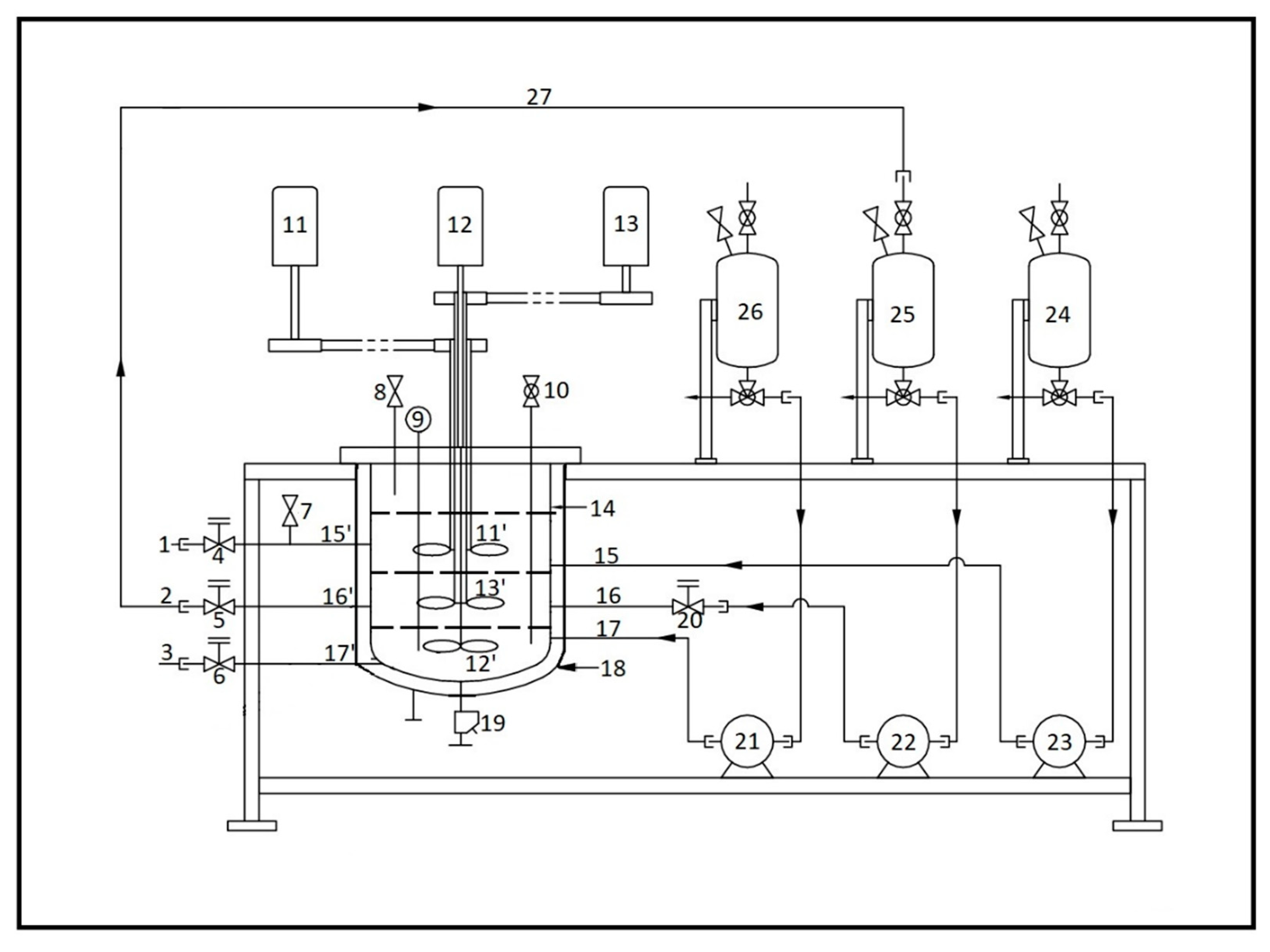
The continuous flow stirred multiphase reactor was made up of the reactor vessel, pumping system, and feed vessels (see Figure 1 and Figure 2). The reactor vessel (see Figures S1 and S2) was made up of glass. As shown in Figure 2, three concentric stirrers (11′, 12′, 13′) with motors (11, 12, 13) were installed to agitate each phase independently with independent speeds of agitation. Thus, it was possible to have independent control over mass transfer rates. Flat (paddle) impellers were used. All stirrers were adjustable in height. The position of the upper organic phase stirrer (11′) was such that it resided in the organic phase. The position of the lower aqueous phase stirrer (12′) was such that it resided in the aqueous phase and middle phase stirrer (13′) resided in the middle phase. No baffles were used in the reactor to maintain the steady-state phases. However, baffles can be used depending on the situation. Three separate motors (11, 12, 13) were used to control the agitation of each stirrer, and three pumps (21, 22, 23) were used to pump the three phases independently in the reactor. Independent inlet (15, 16, 17) and outlet nozzles (15′, 16′, 17′) were provided for each phase. A jacketed heating system (18) was used for heating. Water was used in the jacket as the heating medium. To control the flow rate, metering valves (4, 5, 6) were installed at the outlet of each phase, and one metering valve (20) was installed at the inlet of the middle phase. The outlet of metering valves (1, 2, 3) was connected to collection vessels. A sampling valve (7) was installed to take an online sample of the organic phase for reaction monitoring and analysis. At the lower end of the reactor, a drain valve (19) was installed. Three feed vessels (24, 25, 26) were used to store each phase feed. Three single piston pumps (21, 22, 23) with pulse dampeners were used to pump each phase at the respective inlets. This arrangement (27) was made to circulate the middle phase continuously if needed. A thermowell with a thermocouple (9) was provided to monitor the temperature of the reaction mixture. The overflow tube (8) and an adjustable sampling tube with a feed system (10) was installed at the top (see Figure S3). The flow rate of the inlet and outlet and speed of agitation of stirrers were set so that it maintained steady three phases during the reaction. The material of construction of the reactor was glass and SS316. Additionally, the reactor was operated in batch and continuous modes [32].

2.3. Reaction Procedure

The reaction was carried with guaiacol and epichlorohydrin using tetra-butyl ammonium bromide (TBAB) as a phase transfer catalyst, which formed guaiacol glycidyl ether as a product. The reaction mixture was prepared with 0.1 mol guaiacol, 0.2 mol sodium hydroxide, 0.14 mol tetra-n-butylammonium bromide, and 0.6 mol sodium chloride dissolved in water to make up the volume of the aqueous phase to 150 cm3 and 0.1 mol epichlorohydrin, and 0.03 mol n-decane as internal standards were dissolved in toluene to make up the volume of the organic phase to 150 cm3. The whole reaction mixture was stirred in the reactor, which formed three phases after settlement. For batch processing, the same reactor tank was used with three concentric stirrers to agitate each phase independently with independent speeds of agitation. The pump and metering valve did not operate during the batch operation.
For continuous reaction processing, feed solutions were prepared. The aqueous phase feed was prepared with 0.1 mol guaiacol, 0.2 mol sodium hydroxide, and 0.6 mol sodium chloride dissolved in water to make up the volume of the aqueous phase to 150 cm3. The organic phase feed was prepared with 0.1 mol epichlorohydrin and 0.03 mol n-decane as internal standards dissolved in toluene to make up the volume of the organic phase to 150 cm3. Both aqueous and organic feeds were stored in the respective feed vessels.
After preparing the reaction mixture in the reaction vessel, the organic and aqueous phases were pumped to the continuous flow stirred multiphase reactor through the separate inlet. The organic and aqueous phase flow rate was in the range of 0.5–1.3 mL/min, and a typical reaction was conducted at 40 °C. The metering valve was used to control the flow rate at the outlet of each phase. The samples of the organic phase were taken from the organic phase sampling valve for analysis until the steady state was reached. In all experiments, to study the stability of the steady state, the samples were also taken after a steady state was reached (till 6 h).

2.4. Method of Analysis

During the reaction, samples were periodically withdrawn from the organic phase and analysed using gas chromatography on a Thermo Trace GC1110 model equipped with a flame ionisation detector using a TG-MS 1 (30 m × 0.2 5mm × 0.25 um) column. The conversion was based on the disappearance of epichlorohydrin in the organic phase against n-decane as the internal standard. The product confirmation was done by Thermo Scientific Q Exactive Orbitrap GC-MS (HR-MS).

3. Results and Discussion

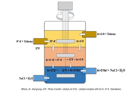
In the continuous flow stirred multiphase reactor, the reaction of guaiacol and epichlorohydrin with TBAB as a phase transfer catalyst was carried out, which formed guaiacol glycidyl ether as the product (Scheme 1) (Supplementary Materials Figures S4 and S5). Figure 3 shows how mass transfer occurs across the two interfaces and the reaction takes place in the middle phase. The aqueous phase reactant (anion) forms an ion pair with TBAB, which is then transferred to the middle catalyst phase because of the concentration gradient and favourable distribution in the middle phase. Similarly, the organic phase reactant (cation) diffuses to the middle catalyst phase, where the reaction takes place, and the product is formed. Because of the solubility of the product in the organic phase with favourable distribution and the concentration gradient, the product diffuses to the upper organic phase and is transferred through the organic phase outlet.

3.1. Batch Stirred Multiphase Reactor

The reactor was operated in batch mode, and different reaction parameters affecting conversion and selectivity were studied and optimised.

3.1.1. Effect of Speed of Agitation in a Batch Stirred Multiphase Reactor

In all experiments, the speed of agitation of all three stirrers was adjusted in such a way that all three phases maintained a steady state without mixing. From the experiments, it was observed that above 60 rpm, all phases started to ripple out because of increasing turbulence. Therefore, the experiment was carried out at 60 rpm. An 89% conversion of epichlorohydrin and 94% selectivity of guaiacol glycidyl ether were obtained at 60 rpm (see Figure 4).
To study the effect of the speed of agitation in each phase, different speeds of agitation were set for each phase. Here, the speed of agitation (in rpm) of the aqueous phase is denoted by A, the middle catalyst phase by M, and the organic phase by O. It was observed that at a lower aqueous phase speed and a higher middle phase speed, the conversion of epichlorohydrin was higher, but the selectivity of guaiacol glycidyl ether decreased by 10% (see Figure 4). As shown in Figure 4, the conversion was similar in the first three cases (89–91%). However, in the case of A-25, M-60, O-60, the conversion dropped by 5%. In this case, at the speeds of A-25 and M-60, the rate of transfer of the aqueous phase reactant (anion) to the middle phase catalyst was reduced, and therefore the conversion dropped by 5%. In the case of A-25, M-80, O-60, and A-25, M-60, O-80, the higher speed of agitation of the middle and the organic phase increased the mixing and increased mass transfer rates correspondingly; therefore, in the middle phase, where the reaction occurs, a larger number of product molecules reacted with guaiacol molecules present in the middle catalyst phase and hence formed the by-product, thereby reducing selectivity (see Scheme 2). In the case of A-60, M-60, O-60, the speed was the same; therefore, the rate of transfer of the aqueous and organic phase reactants was the same. Hence, the highest selectivity of 94% was obtained. The independent stirrer for each phase and the absence of baffles prevented mixing and helped to maintain the steady state of each phase without disturbing the two L-L interfaces.

3.1.2. Effect of Mole Ratio of Guaiacol to Epichlorohydrin

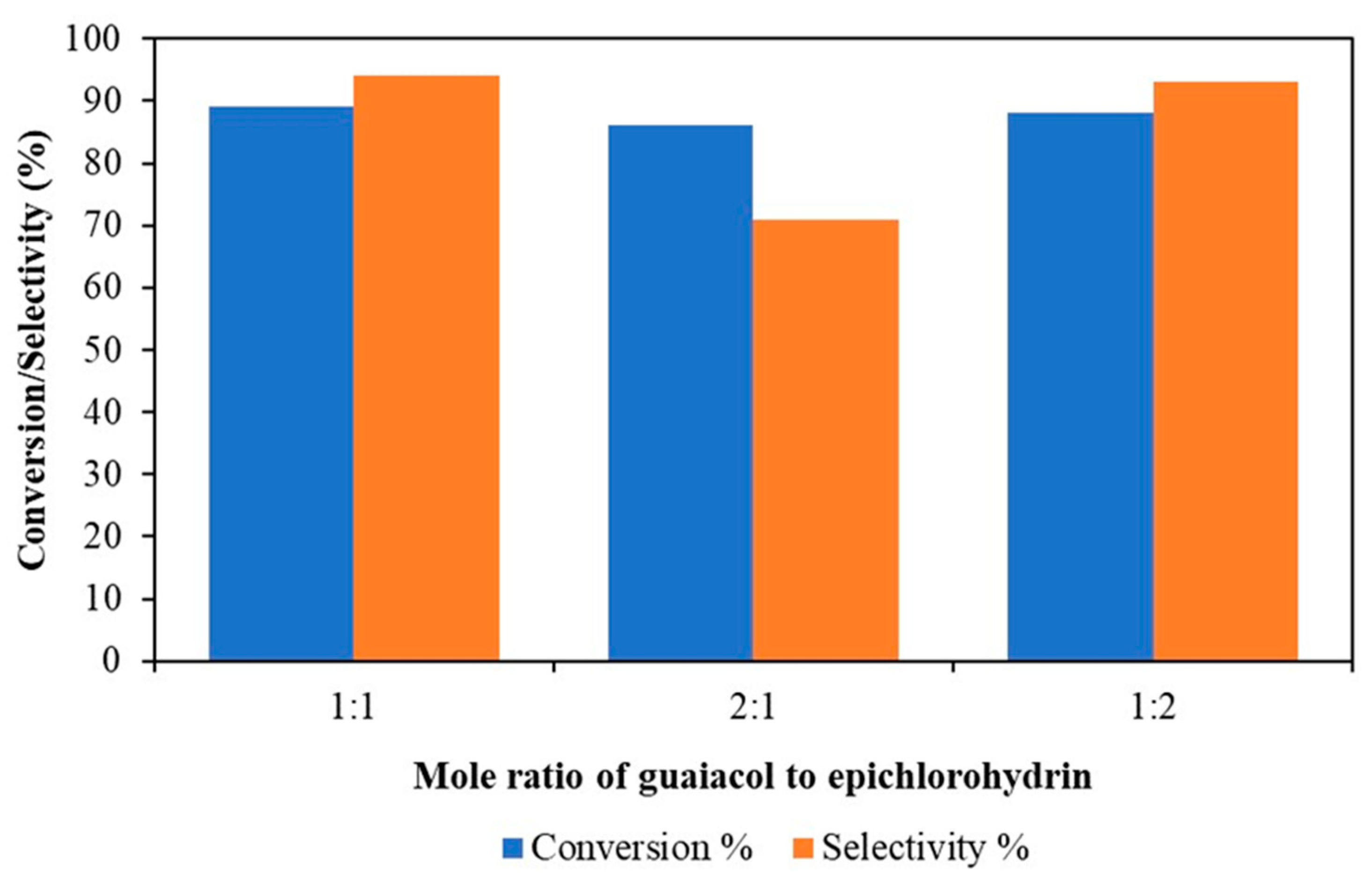
To study the effect of the mole ratio of guaiacol to epichlorohydrin, different mole ratios of guaiacol to epichlorohydrin were studied (1:1, 2:1, and 1:2) under the same conditions with a constant mole ratio between guaiacol and sodium hydroxide (see Figure 5). As guaiacol concentration increases, the selectivity of guaiacol glycidyl ether decreases from 94% to 71%. At a 2:1 guaiacol to epichlorohydrin mole ratio, the excess of guaiacol attacks the ring carbon product via the SN2 mechanism, forming a by-product (II) (see Scheme 1 and Scheme 2 and Supplementary Materials Figures S4 and S5) and reduces the selectivity of guaiacol glycidyl ether. An 89% conversion of epichlorohydrin and 94% selectivity of guaiacol glycidyl ether were the same for guaiacol to epichlorohydrin mole ratios of 1:1 and 1:2. Therefore, a 1:1 mole ratio was used for further experiments.

3.1.3. Effect of Mole Ratio of Guaiacol to Sodium Hydroxide

The effect of the mole ratio of guaiacol to sodium hydroxide was studied, from 1:1 to 1:2 (see Figure 6). At a lower concentration of sodium hydroxide, the conversion and selectivity decrease. This is because guaiacol (pKa 9.98) is a less acidic molecule compared to acetic acid (pKa 4.76) at room temperature [33]. Therefore, it needs a larger amount of sodium hydroxide to form a salt, which takes part in the reaction. The highest conversion (89%) of epichlorohydrin and the 94% selectivity of guaiacol glycidyl ether were obtained for a 1:2 mole ratio. Therefore, this was used for further experiments.

3.1.4. Effect of Temperature

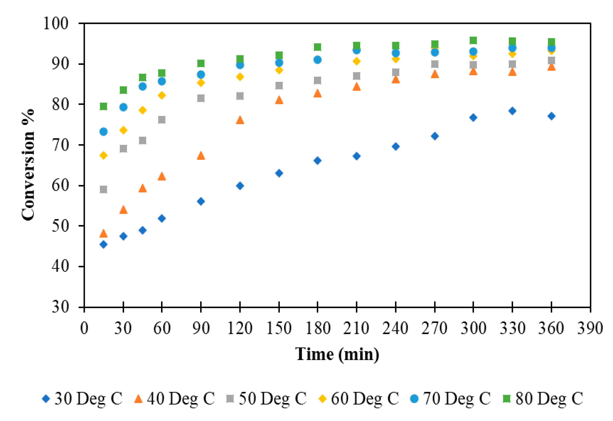
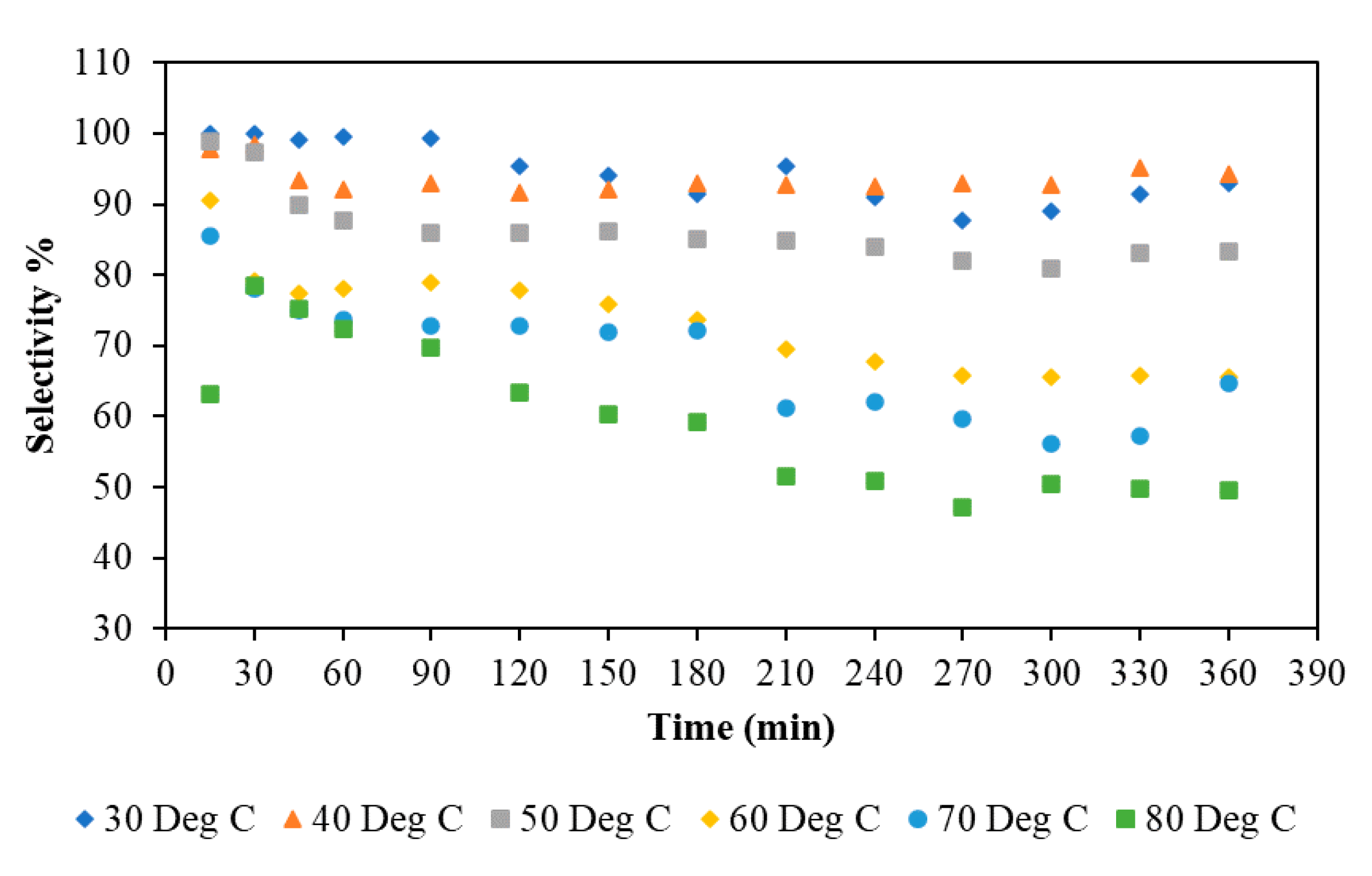
The effect of temperature on the reaction between guaiacol and epichlorohydrin was studied with optimised reaction parameters. The temperature was increased from 30 to 80 °C. At all temperatures, all three phases maintained a steady state without mixing. The conversion of epichlorohydrin was increased with an increase in the temperature, while selectivity considerably dropped with an increase in temperature. The conversion was increased due to an increase in temperature and the formation of by-product increased (see Scheme 2). An 89% conversion of epichlorohydrin and 94% selectivity of guaiacol glycidyl ether were obtained at 40 °C, and a 95% conversion of epichlorohydrin and 50% selectivity of guaiacol glycidyl ether were obtained at 80 °C. Therefore, 40 °C was considered as the optimum temperature for further experiments. The effect of temperature on the conversion and selectivity is given in Figure 7 and Figure 8.

3.1.5. Comparison of Batch Stirred Multiphase Reactor with Conventional Single Stirrer PTC Batch Reactor

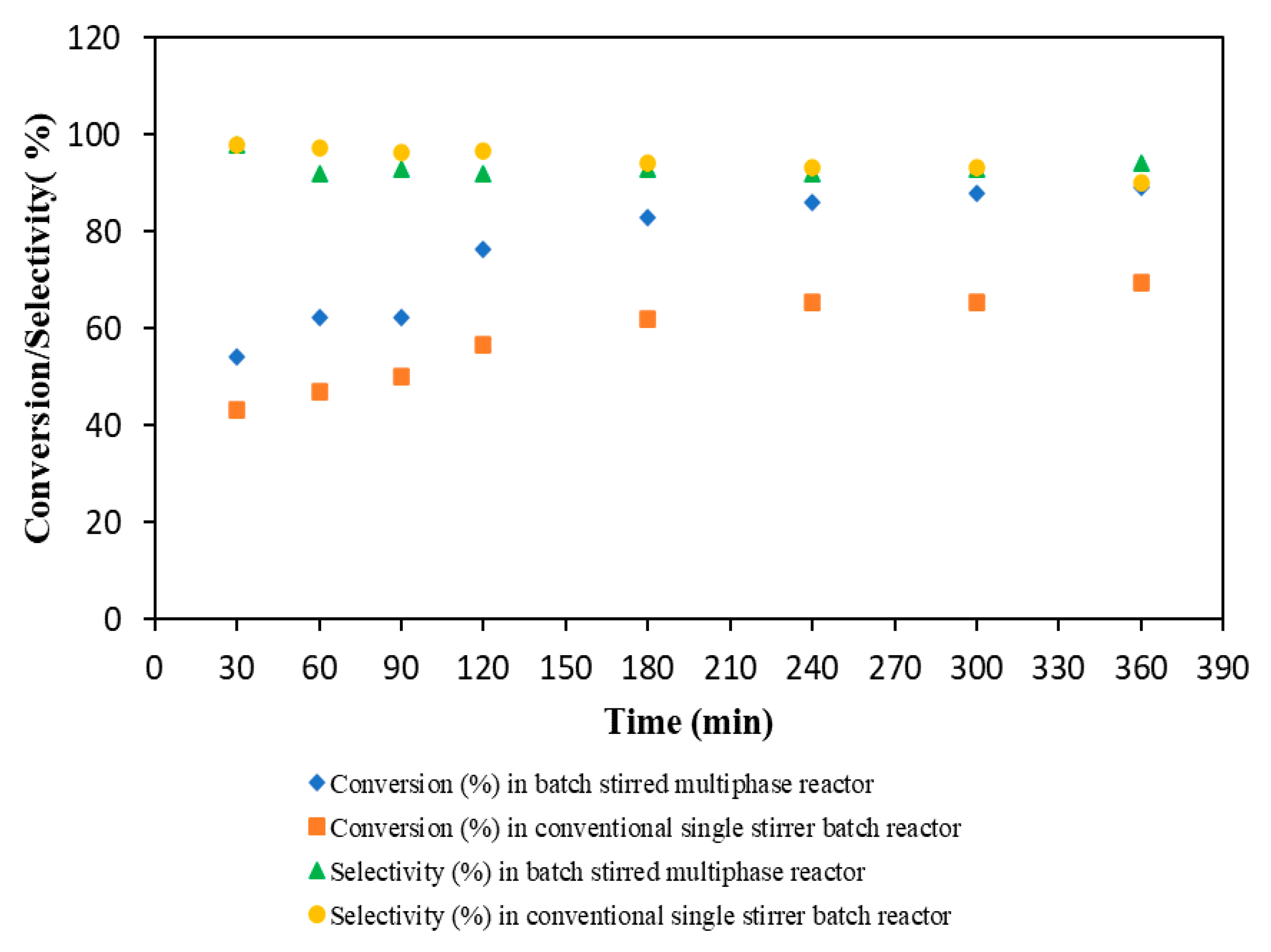
We compared our batch stirred multiphase reactor with a conventional single stirrer PTC batch reactor (see Figure 9). In our reactor, the agitation of each phase by the individual stirrer increased the mass transfer rate. Therefore, a 19% increase in the conversion of epichlorohydrin and a 4% increase in the selectivity of guaiacol glycidyl ether were observed compared to the conventional single stirrer PTC batch reactor.

3.2. Continuous Flow Stirred Multiphase Reactor

The reactor was operated in continuous mode, and different reaction conditions affecting conversion and selectivity were studied and optimised.

3.2.1. The Effect of Speed of Agitation in a Continuous Flow Stirred Multiphase Reactor

The speed of agitation of all three stirrers was adjusted in such a way that all three phases maintained a steady state without mixing. It was observed that above 60 rpm, all phases started to ripple out. So, the reaction was carried out at 60 rpm. In the case of the same speed of agitation of each phase, the highest conversion (76%) of epichlorohydrin and 85% selectivity of guaiacol glycidyl ether were obtained. The experiments were also performed at a different speed of agitation for all three phases. It was found that the conversion of epichlorohydrin decreases slightly while the selectivity of guaiacol glycidyl ether decreases by 9–10% (see Figure 10).
In Figure 10, at A-60, M-60, O-60 rpm, the highest conversion and selectivity were achieved. In the case of the experiment with A-25, M-80, O-60 rpm, the speed of the aqueous phase was 25 rpm; therefore, the rate of transfer of the aqueous phase reactant (anion) to the middle phase catalyst was reduced, and conversion dropped by 8%. The speed of the middle phase was 80 rpm, which increased the mixing; therefore, a larger number of product molecules collided with guaiacol molecules present in the middle catalyst phase and formed the by-product, thereby reducing selectivity by 8% (see Scheme 2). As the guaiacol molecules reacted with the product, a smaller number of molecules were available for epichlorohydrin to form the product, which also resulted in a drop in conversion. Similarly, in the case of experiments with A-40, M-80, O-60 rpm, the conversion dropped by 3%, and selectivity dropped by 9%. When the speed of the aqueous phase was 40 rpm, the conversion dropped by just 3%.
In previously reported continuous reactors, because of the high speed of the stirrer, the catalyst phase mixed with the organic and aqueous phases, and also the presence of baffles resulted in the mixing of three phases. This ultimately led to the catalyst phase flowing out of the reactor, along with the organic and aqueous phases. Thereby, the conversion dropped over a period as the loss of catalyst occurred [29,30,31]. In this reactor (named as “Yadav reactor [32]”after the inventor and corresponding author), to prevent vigorous mixing of the three phases, a separate stirrer for each phase was used, and the speed of agitation was maintained in such way that all three phases maintained a steady interface which prevented the catalyst phase from flowing out of the reactor and also gave the best conversion and selectivity. This reactor design also reduced the cost of membranes used in the previously reported reactor to separate the phases [30,31].

3.2.2. Effect of Flow Rate in a Continuous Flow Stirred Multiphase Reactor

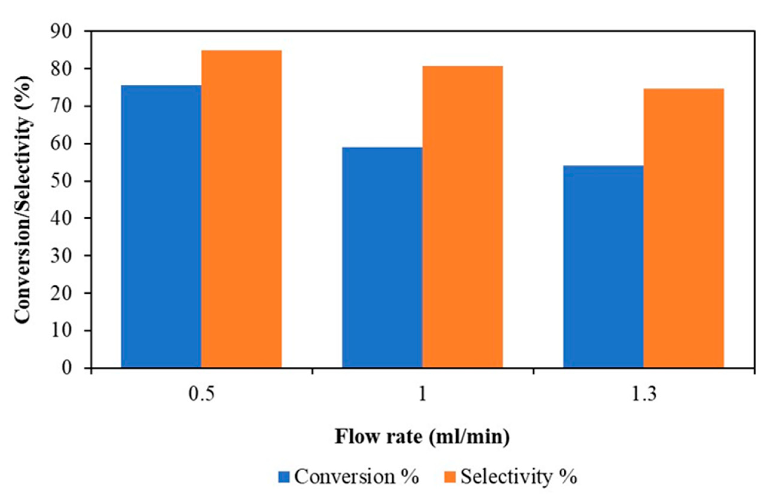
The experiments were performed at the same speed of agitation for all three phases, i.e., 60 rpm, with three different flow rates of the aqueous and organic phase. It was found that at a lower flow rate, high conversion and selectivity were obtained. As the flow rates of both phases increased from 0.5 to 1.3 mL/min, the resident time decreased, which resulted in a drastic decrease in the conversion of epichlorohydrin, from 76% to 54%, and selectivity of guaiacol glycidyl ether, from 85% to 75% (see Figure 11).
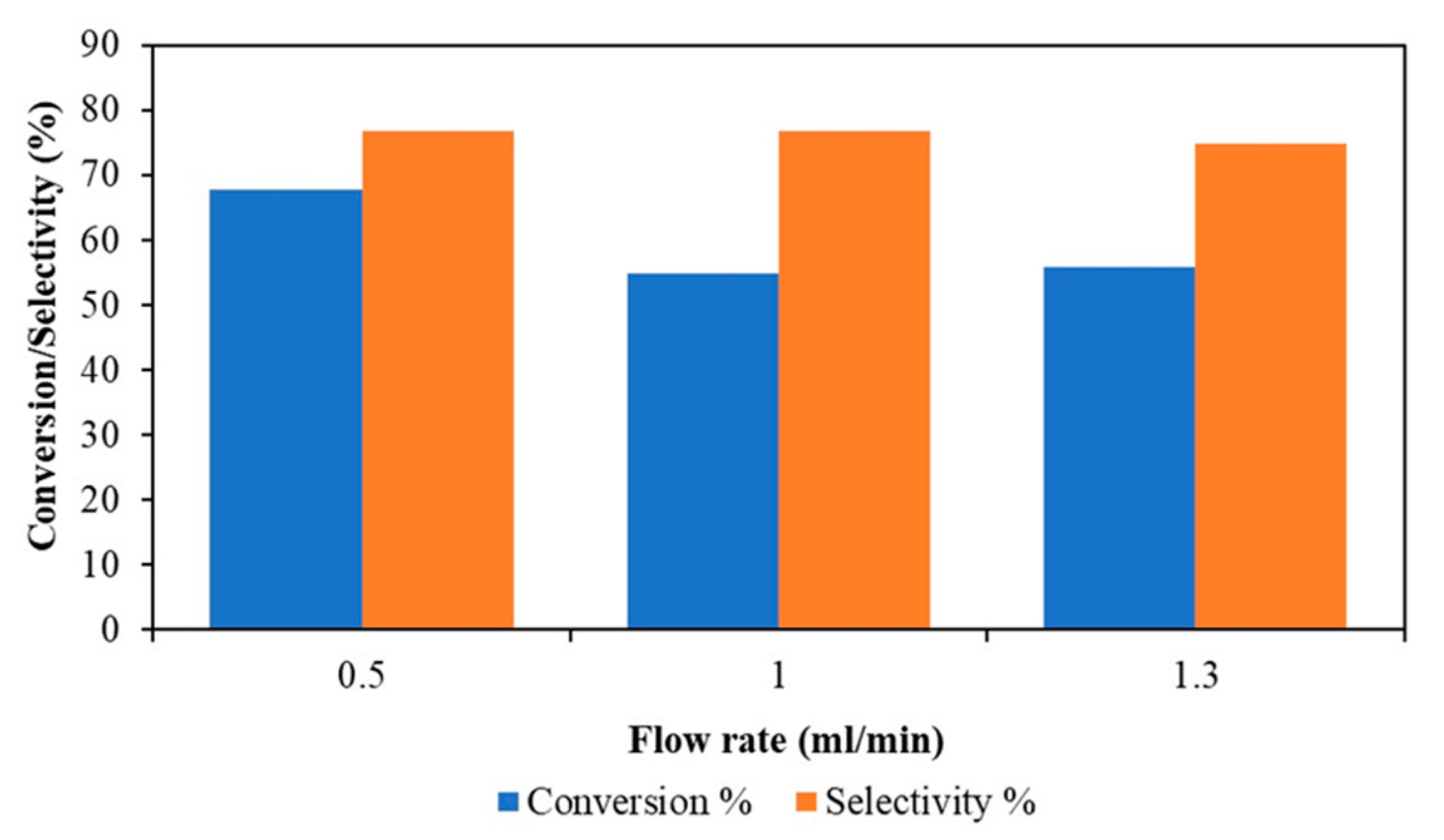
Experiments were also performed at different speeds of agitation for all three phases. As the flow rate increased, the conversion of epichlorohydrin decreased from 68% to 56%, and the selectivity of guaiacol glycidyl ether decreased from 77% to 75% (see Figure 12).
In previously reported continuous reactors, the countercurrent flow of aqueous and organic phases distributed the middle catalyst-rich phase in an organic and aqueous phase, which resulted in the catalyst phase flowing out of the reactor along with the organic and aqueous phases [29,30,31]. In this reactor, to avoid the mixing of the three phases and to maintain a steady state of each phase, the countercurrent flow of the aqueous and organic phases was avoided. In addition, the speed of agitation was maintained, as described in Section 3.2.1. The organic and aqueous phases were introduced from the independent inlets. The organic phase inlet directly opens into the lower part of the organic phase layer, just above the middle catalyst phase layer, and the aqueous phase inlet directly opens into the upper part of the aqueous phase layer, just below the middle catalyst phase layer (see Figure 2 and Figure 3 and Figures S1 and S2). This arrangement provides a fresh feed of reactants to the middle catalyst phase, where the actual reaction occurs. Because of the concentration gradient, only reactant ions are transferred across the two interfaces of the middle catalyst phase. In all experiments at each flow rate, the middle catalyst phase volume was retained with undisturbed interfaces, thereby leading to steady conversion and selectivity.

3.2.3. Effect of Middle Catalyst Phase Recirculation in a Continuous Flow Stirred Multiphase Reactor

The experiment was carried out with continuous circulation of the middle catalyst phase using the pump and metering valves; there was no loss of catalyst phase at the end of the reaction. The result was similar to that for the reaction where the steady middle catalyst phase was used. No significant increase in conversion of epichlorohydrin and selectivity of guaiacol glycidyl ether was observed. Therefore, for all further experiments, the middle catalyst phase was not recirculated; it was kept in a steady state.

3.2.4. Time on Stream Study in a Continuous Flow Stirred Multiphase Reactor

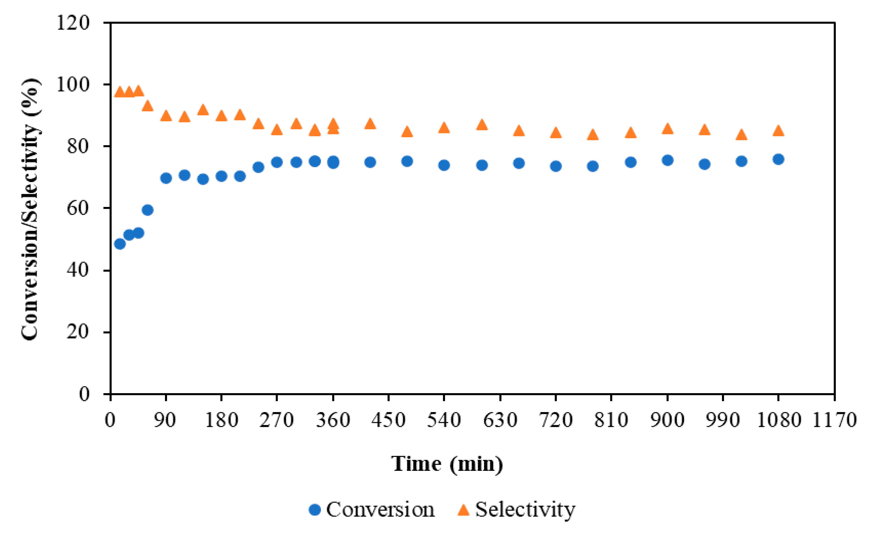
The time on stream (TOS) study was carried out for 18 h at 40 °C with 60 rpm as the speed of agitation for all three stirrers. The aqueous and organic phase flow rate was kept at 0.5 mL/min. Conversion of 76% of epichlorohydrin and 85% selectivity of guaiacol glycidyl ether were constant throughout the reaction (see Figure 13). There was no loss of the catalyst phase, even at the end of 18 h. In previously reported continuous reactors, the loss of the catalyst phase occurred, as it flowed out along with the other phases [29,30,31]. Here, in the Yadav reactor, to maintain the steady state of each phase, the parameters discussed in the above sections were used. The adjustable independent stirrer for each phase and flat (paddle) impellers and the absence of baffles prevented the mixing of phases, keeping the two interfaces steady. The use of pumps at the inlet and metering valves at the outlet maintained the steady inlet and outlet flows of aqueous and organic phases. Thereby, a constant volume of each phase was maintained. In the entire operation for a long period of time (time on stream, TOS), the catalyst phase retained its original volume, along with the chemical activity. The design of the reactor and reaction parameters successfully converted the batch L-L-L PTC reaction system into a continuous system.

4. Conclusions

The present work described a novel approach in the design of a multiphase reactor in a continuous operation mode for L-L-L PTC reactions. The catalyst phase was operated continuously, which gave the best activity with steady conversion and selectivity. The catalyst phase retained its volume as there was no physical loss of the catalyst phase from the reactor. In batch mode, using three concentric stirrers at as low as 60 rpm gave the best conversion and selectivity compared to those of the conventional batch reactor. In the case of continuous mode, at 40 °C, the conversion of epichlorohydrin was 76% with a selectivity of guaiacol glycidyl ether of 85%. The time on stream study showed that the reaction could be carried out continuously without the shutdown of the process and with continuous reuse of the middle catalyst phase. Throughout the experiments, all three phases were steady without any change of conversion and selectivity. By using this process, industrially important guaiacol glycidyl ether was synthesised in continuous mode. The continuous flow stirred multiphase reactor can be used for various industrial L-L-L PTC reactions.

5. Patent

Yadav, G.D. An Improved Continuous Flow Stirred Multiphase Reactor. Patent PCT/IN2018/050535, 21 February 2019.

Supplementary Materials

The following are available online at https://www.mdpi.com/2227-9717/8/10/1271/s1, Figure S1: Schematic diagram of the front section the reactor vessel, Figure S2: Front view of the actual reactor vessel, Figure S3: Schematic diagram of a top view of the reactor vessel, Figure S4: GCMS spectra of (A) epichlorohydrin, (B) guaiacol glycidyl ether, (C) reaction by-product, and (D) n-decane, Figure S5: Typical GC chromatogram of reaction mass.

Author Contributions

N.H.M. contributed to the supervision of reactor fabrication at the fabricator site, conducting reactions in the continuous flow stirred multiphase reactor and analysed the reaction mixture with analytical instruments, and wrote the original draft. G.D.Y. contributed to the original idea of designing of the continuous flow stirred multiphase reactor, provided funds, provided research supervision and research infrastructure, and reviewed and edited the draft. All authors have read and agreed to the published version of the manuscript.

Funding

N.H.M. is grateful to the University Grants Commission (UGC) for a BSR Fellowship in Sciences for meritorious students under its Green Technology program. G.D.Y. received support from R. T. Mody Distinguished Professor Endowment and Tata Chemicals Darbari Seth Distinguished Professor of Leadership and Innovation Endowment, and the J. C. Bose National Fellowship of the Department of Science and Technology, Government of India.

Conflicts of Interest

The authors declare no conflict of interest.

References

  1. Starks, C.M.; Liotta, C. Phase Transfer Catalysis Principles and Techniques; Academic Press: New York, NY, USA, 1978. [Google Scholar]
  2. Makosza, M. Phase-transfer catalysis. A general green methodology in organic synthesis. Pure Appl. Chem. 2000, 72, 1399–1403. [Google Scholar] [CrossRef] [Green Version]
  3. Naik, S.D.; Doraiswamy, L.K. Phase transfer catalysis: Chemistry and engineering. AIChE J. 1998, 44, 612–646. [Google Scholar] [CrossRef]
  4. Yadav, G.D.; Sowbna, P.R. Process intensification and waste minimization in liquid–liquid–liquid phase transfer catalyzed selective synthesis of mandelic acid. Chem. Eng. Res. Des. 2012, 90, 1281–1291. [Google Scholar] [CrossRef]
  5. Yadav, G.D. Insight into Green Phase Transfer Catalysis. Top. Catal. 2004, 29, 145–161. [Google Scholar] [CrossRef]
  6. Wang, D.H.; Weng, H.S. Preliminary study on the role played by third liquid phase in phase transfer catalysis. Chem. Eng. Sci. 1988, 43, 2019–2024. [Google Scholar] [CrossRef]
  7. Mason, D.; Magdassi, S.; Sasson, Y. Role of a third liquid phase in phase-transfer catalysis. J. Org. Chem. 1991, 56, 7229–7232. [Google Scholar] [CrossRef]
  8. Wang, D.H.; Weng, H.S. Solvent and salt effects on the formation of third liquid phase and the reaction mechanisms in the phase transfer catalysis system—Reaction between N-butyl bromide and sodium phenolate. Chem. Eng. Sci. 1995, 50, 3477–3486. [Google Scholar] [CrossRef]
  9. Hsiao, H.C.; Kao, S.M.; Weng, H.S. Synthesis of n-Butyl Phenyl Ether by Tri-Liquid-Phase Catalysis Using Poly(ethylene glycol)-600 as a Catalyst. 1. Analysis of Factors Affecting the Formation of a Third Liquid Phase. Ind. Eng. Chem. Res. 2000, 39, 2772–2778. [Google Scholar] [CrossRef]
  10. Ohtani, N.; Ohta, T.; Hosoda, Y.; Yamashita, T. Phase Behavior and Phase-Transfer Catalysis of Tetrabutylammonium Salts. Interface-Mediated Catalysis. Langmuir 2004, 20, 409–415. [Google Scholar] [CrossRef]
  11. Yadav, G.D.; Jadhav, Y.B.; Sengupta, S. Selectivity engineered phase transfer catalysis in the synthesis of fine chemicals: Reactions of p-chloronitrobenzene with sodium sulphide. J. Mol. Catal. A Chem. 2003, 200, 117–129. [Google Scholar] [CrossRef]
  12. Yadav, G.D.; Badure, O.V. Role of Third Phase in Intensification of Reaction Rates and Selectivity: Phase-Transfer Catalyzed Synthesis of Benzyl Phenyl Ether. Ind. Eng. Chem. Res. 2007, 46, 8448–8458. [Google Scholar] [CrossRef]
  13. Yadav, G.D.; Sowbna, P.R. Selectivity Engineering in Synthesis of 4-Benzyloxy Propiophenone Using Liquid–Liquid–Liquid Phase-Transfer Catalysis. Ind. Eng. Chem. Res. 2012, 51, 3256–3264. [Google Scholar] [CrossRef]
  14. Yadav, G.D.; Motirale, B.G. Selective oxidation of methyl mandelate to methyl phenyl glyoxylate using liquid–liquid–liquid phase transfer catalysis. Chem. Eng. J. 2010, 156, 328–336. [Google Scholar] [CrossRef]
  15. Katole, D.O.; Yadav, G.D. Process intensification and waste minimization using liquid-liquid-liquid tri-phase transfer catalysis for the synthesis of 2-((benzyloxy)methyl)furan. Mol. Catal. 2019, 466, 112–121. [Google Scholar] [CrossRef]
  16. Yang, H.; Chen, Y. Ultrasound-assisted third-liquid phase-transfer catalyzed esterification of potassium 4-methoxyphenylacetate by dual-site phase-transfer catalyst. J. Taiwan Inst. Chem. Eng. 2012, 43, 897–903. [Google Scholar] [CrossRef]
  17. Yang, H.M.; Lin, D.W. Third-liquid phase-transfer catalyzed esterification of sodium benzoate with novel dual-site phase-transfer catalyst under ultrasonic irradiation. Catal. Commun. 2011, 14, 101–106. [Google Scholar] [CrossRef]
  18. Yang, H.M.; Chen, C.H. Catalytic esterification of sodium salicylate in third-liquid phase under ultrasound-assisted tri-liquid phase-transfer catalysis. J. Mol. Catal. A Chem. 2009, 312, 107–113. [Google Scholar] [CrossRef]
  19. Huang, C.C.; Yang, H.M. Kinetics for benzoylation of sodium 4-acetylphenoxide via third-liquid phase in the phase-transfer catalysis. Appl. Catal. A Gen. 2005, 290, 65–72. [Google Scholar] [CrossRef]
  20. Yang, H.-M.; Huang, C.-C. Catalytic Benzoylation of 4-Chloro-3-methylphenol Sodium Salt in Third-Liquid Phase under Conditions of Phase-Transfer Catalysis. Ind. Eng. Chem. Res. 2007, 46, 7915–7920. [Google Scholar] [CrossRef]
  21. Yang, H.; Hung, Y.; Tu, C. Synthesis of butyl salicylate by phase-transfer catalysis with dual-site phase-transfer catalyst and ionic liquid in tri-liquid system. J. Taiwan Inst. Chem. Eng. 2014, 45, 1421–1427. [Google Scholar] [CrossRef]
  22. Yang, H.M.; Li, C.C. Kinetics for synthesizing benzyl salicylate by third-liquid phase-transfer catalysis. J. Mol. Catal. A Chem. 2006, 246, 255–262. [Google Scholar] [CrossRef]
  23. Kopeć, D.; Baj, S.; Siewniak, A. Ultrasound-Assisted Green Synthesis of Dialkyl Peroxides under Phase-Transfer Catalysis Conditions. Molecules 2020, 25, 118. [Google Scholar] [CrossRef] [PubMed] [Green Version]
  24. Zhao, Q.; Sun, J.; Liu, B.; He, J. Novel kinetics model for third-liquid phase-transfer catalysis system of the “complex” carbanion: Competitive role between catalytic cycles. Chem. Eng. J. 2015, 280, 782–795. [Google Scholar] [CrossRef]
  25. Zhao, Q.; Yang, L.; Shen, Y. Third-Liquid Phase Transfer Catalysis for Horner–Wadsworth–Emmons Reactions of “Moderately Acidic” and “Weakly Acidic” Phosphonates. Ind. Eng. Chem. Res. 2016, 55, 7604–7611. [Google Scholar] [CrossRef]
  26. Zhao, Q.; Zhao, X.; Sun, J.; Yang, L.; Shen, Y. Catalytic Process for the Hydroxide-Initiated Reaction of the “Weakly Acidic” Substrate in the Third-Liquid Phase-Transfer Catalytic System. Ind. Eng. Chem. Res. 2018, 57, 13318–13326. [Google Scholar] [CrossRef]
  27. Yadav, G.D.; Sowbna, P.R. Modeling of microwave irradiated liquid–liquid–liquid (MILLL) phase transfer catalyzed green synthesis of benzyl thiocyanate. Chem. Eng. J. 2012, 179, 221–230. [Google Scholar] [CrossRef]
  28. Yadav, G.D.; Reddy, C.A. Kinetics of the n-Butoxylation of p-Chloronitrobenzene under Liquid−Liquid−Liquid Phase Transfer Catalysis. Ind. Eng. Chem. Res. 1999, 38, 2245–2253. [Google Scholar] [CrossRef]
  29. Weng, H.S.; Wang, C.M.; Wang, D.H. A Preliminary Study on a Continuous Flow Stirred Vessel Reactor for Tri-Liquid-Phase Phase Transfer Catalysis. Ind. Eng. Chem. Res. 1997, 36, 3613–3618. [Google Scholar] [CrossRef]
  30. Yang, H.M.; Peng, G.Y. Ultrasound-assisted third-liquid phase-transfer catalyzed esterification of sodium salicylate in a continuous two-phase-flow reactor. Ultrason. Sonochem. 2010, 17, 239–245. [Google Scholar] [CrossRef]
  31. Yang, H.M.; Huang, Y.S. Green benzylation of sodium salicylate by phase-transfer catalysis with third-liquid phase in a continuous two-phase-flow reactor. J. Taiwan Inst. Chem. Eng. 2011, 42, 265–270. [Google Scholar] [CrossRef]
  32. Yadav, G.D. An Improved Continuous Flow Stirred Multiphase Reactor. Patent PCT/IN2018/050535, 21 February 2019. [Google Scholar]
  33. The Engineering ToolBox. Available online: https://www.engineeringtoolbox.com/paraffinic-benzoic-hydroxy-dioic-acids-structure-pka-carboxylic-dissociation-constant-alcohol-phenol-d_1948.html (accessed on 19 September 2020).
Figure 1. Front view of the actual continuous flow stirred multiphase reactor.
Processes 08 01271 g001
Figure 2. Schematic diagram of the continuous flow stirred multiphase reactor. 1—outlet for organic phase metering valve, 2—outlet for middle phase metering valve, 3—outlet for aqueous phase metering valve, 4—organic phase metering valve, 5—middle phase metering valve, 6—aqueous phase metering valve, 7—sampling valve for organic phase, 8—overflow tube, 9—thermowell with thermocouple, 10—adjustable sampling tube with feed system, 11—motor for organic phase, 12—motor for aqueous phase, 13—motor for middle phase, 11′—stirrer for organic phase, 12′—stirrer for aqueous phase, 13′—stirrer for middle phase, 14—reactor glass vessel, 15—inlet for organic phase, 16—inlet for middle phase, 17—inlet for aqueous phase, 15′—outlet for organic phase, 16′—outlet for middle phase, 17′—outlet for aqueous phase, 18—jacketed heating system, 19—drain valve, 20—metering valve at middle phase inlet, 21—aqueous phase pump, 22—middle phase pump, 23—organic phase pump, 24—organic phase feed vessel, 25—middle phase feed vessel, 26—aqueous phase feed vessel, 27—arrangement to circulate the middle phase continuously.
Processes 08 01271 g002
Scheme 1. Synthesis of guaiacol glycidyl ether.
Processes 08 01271 sch001
Figure 3. Liquid-liquid-liquid (L-L-L PTC) reaction in a continuous flow stirred multiphase reactor.
Processes 08 01271 g003
Figure 4. Effect of the speed of agitation in batch stirred multiphase reactor. Epichlorohydrin 0.1 mol, n-decane 0.03 mol, toluene 150 cm3, guaiacol 0.1 mol, sodium hydroxide 0.2 mol, sodium chloride 0.6 mol, tetra-n-butylammonium bromide 0.14 mol, and water 150 cm3. Temperature 40 °C, A—speed of agitation of lower aqueous phase, M—speed of agitation of middle catalyst phase, O—speed of agitation of upper organic phase, reaction time 6 h.
Processes 08 01271 g004
Scheme 2. By-product formation reaction.
Processes 08 01271 sch002
Figure 5. Effect of the mole ratio of guaiacol to epichlorohydrin. N-decane 0.03 mol, toluene 150 cm3, sodium chloride 0.6 mol, tetra-n-butylammonium bromide 0.14 mol, and water 150 cm3. Temperature 40 °C, speed of agitation 60 rpm for all three phases, and reaction time 6 h.
Processes 08 01271 g005
Figure 6. Effect of the mole ratio of guaiacol to sodium hydroxide. Epichlorohydrin 0.1 mol, n-decane 0.03 mol, toluene 150 cm3, sodium chloride 0.6 mol, tetra-n-butylammonium bromide 0.14 mol, and water 150 cm3. Temperature 40 °C, speed of agitation 60 rpm for all three phases, and reaction time 6 h.
Processes 08 01271 g006
Figure 7. Effect of temperature on the conversion. Epichlorohydrin 0.1 mol, n-decane 0.03 mol, toluene 150 cm3, guaiacol 0.1 mol, sodium hydroxide 0.2 mol, sodium chloride 0.6 mol, tetra-n-butylammonium bromide 0.14 mol, and water 150 cm3. Speed of agitation 60 rpm for all three phases and reaction time 6 h.
Processes 08 01271 g007
Figure 8. Effect of temperature on the selectivity. Epichlorohydrin 0.1 mol, n-decane 0.03 mol, toluene 150 cm3, guaiacol 0.1 mol, sodium hydroxide 0.2 mol, sodium chloride 0.6 mol, tetra-n-butylammonium bromide 0.14 mol, and water 150 cm3. Speed of agitation 60 rpm for all three phases and reaction time 6 h.
Processes 08 01271 g008
Figure 9. Comparison of batch stirred multiphase reactor with conventional single stirrer PTC batch reactor. Epichlorohydrin 0.1 mol, n-decane 0.03 mol, toluene 150 cm3, guaiacol 0.1 mol, sodium hydroxide 0.2 mol, sodium chloride 0.6 mol, tetra-n-butylammonium bromide 0.14 mol, and water 150 cm3. Temperature 40 °C, novel PTC reactor speed of agitation 60 rpm for all three phases, conventional PTC reactor speed of agitation 1200 rpm, and reaction time 6 h.
Processes 08 01271 g009
Figure 10. Effect of speed of agitation in a continuous flow stirred multiphase reactor. Epichlorohydrin 0.1 mol, n-decane 0.03 mol, toluene 150 cm3, guaiacol 0.1 mol, sodium hydroxide 0.2 mol, sodium chloride 0.6 mol, tetra-n-butylammonium bromide 0.14 mol, and water 150 cm3. Temperature 40 °C, flow rate for aqueous and organic phase 0.5 mL/min, A—speed of agitation of lower aqueous phase, M—speed of agitation of middle catalyst phase, O—speed of agitation of upper organic phase, and reaction time 6 h.
Processes 08 01271 g010
Figure 11. Effect of the flow rate at the same speed of agitation for three phases. Epichlorohydrin 0.1 mol, n-decane 0.03 mol, toluene 150 cm3, guaiacol 0.1 mol, sodium hydroxide 0.2 mol, sodium chloride 0.6 mol, tetra-n-butylammonium bromide 0.14 mol, and water 150 cm3. Temperature 40 °C, speed of agitation 60 rpm for all three phases, and reaction time 6 h.
Processes 08 01271 g011
Figure 12. Effect of the flow rate at a different speed of agitation for three phases. Epichlorohydrin 0.1 mol, n-decane 0.03 mol, toluene 150 cm3, guaiacol 0.1 mol, sodium hydroxide 0.2 mol, sodium chloride 0.6 mol, tetra-n-butylammonium bromide 0.14 mol, and water 150 cm3, temperature 40 °C, speed of agitation of lower aqueous phase 25 rpm, speed of agitation of middle catalyst phase 80 rpm, speed of agitation of upper organic phase 60 rpm, and reaction time 6 h.
Processes 08 01271 g012
Figure 13. Time on stream study in a continuous flow stirred multiphase reactor. Epichlorohydrin 0.1 mol, n-decane 0.03 mol, toluene 150 cm3, guaiacol 0.1 mol, sodium hydroxide 0.2 mol, sodium chloride 0.6 mol, tetra-n-butylammonium bromide 0.14 mol, and water 150 cm3. Temperature 40 °C, speed of agitation of all three stirrers 60 rpm, and reaction time 18 h (1080 min).
Processes 08 01271 g013