Article

Numerical Modeling of Thermal Flows in Entrance Channels for Polymer Extrusion: A Parametric Study

1
School of Sciences and Humanities, Department of Mathematics, Nazarbayev University, Nur-Sultan 010000, Kazakhstan
2
School of Engineering and Digital Sciences, Mechanical and Aerospace Engineering, Nazarbayev University, Nur-Sultan 010000, Kazakhstan
3
School of Engineering and Digital Sciences, Civil and Environmental Engineering, Nazarbayev University, Nur-Sultan 010000, Kazakhstan
*
Author to whom correspondence should be addressed.
Processes 2020, 8(10), 1256; https://doi.org/10.3390/pr8101256
Submission received: 28 August 2020 / Revised: 15 September 2020 / Accepted: 18 September 2020 / Published: 7 October 2020
(This article belongs to the Section Process Control and Monitoring)

Abstract

:
Flow distribution channels in extrusion dies are typically designed to assure uniform fluid velocity, pressure and temperature in the outlets. To ensure this uniformity, it is desirable to have the fluid melt to reach a steady state temperature in the entrance channel before entering the die body. This paper numerically investigates the temperature distribution of the fluid melt in the entrance channel. Analytical solutions of the velocity and finite element solutions of temperature distribution in Poiseuille flows of polypropylene melt with the Casson rheology model were derived and presented. In the velocity solution, the critical point that separates the core and the remaining parts in the flow was calculated by using the inlet flow rate and the yield stress in the Casson model. The velocity distribution was then substituted into the convective heat equation for temperature distribution simulations. A finite difference scheme was used to obtain the temperature distribution profiles along the flow direction in a parallel-plate, while the finite element model was used to model the flow temperature in circular tubes. The main outcome is the parametric analyses of the effect of various parameters such as radius, wall temperature, inlet temperature, and pressure drop to the optimal length of the channels required for the flow temperature to reach the steady state.

1. Introduction

It is well known that polypropylene can be used to produce low-cost, lightweight, transparent, and flexible thin sheets and films for a variety of applications in industries [1]. The key component in the production of these sheets and films is the extrusion die designs [2,3]. Flow distribution channels in the extrusion dies should be designed in such a way to assure uniform fluid velocity, pressure, temperature in the outlets with uniform thickness [4,5]. If the fluid flow is rapid at the centerline or if the uneven temperature distribution occurs then these scenarios result in extrusion product deformations and surface cracks [6]. Therefore, understanding the Poiseuille flows of polypropylene melt is fundamental for the design of extrusion dies for production of high quality PP sheets and PP films [7,8].
Poiseuille flows of non-Newtonian fluids are well studied in many rheology models [9,10]. For most of the rheology models, analytical and numerical velocity profiles have been available in standard textbooks and literature [11]. The Casson model has often been used to model Non-Newtonian fluids in food industries and it has been used for modeling blood flows [12,13]. Moreover, it can also be used for modeling the polymer flows, particularly, for polypropylene melts. Although the velocity profile is well-known in literature, the connection of the profile with the inlet flow rate and the core size is not explicitly explained [14,15]. When the polymer melt enters an entrance pipe of the die, the melt is at the melting temperature but the die body is kept at a higher temperature anticipating that the melt temperature will rise due to Arrhenius law and the shear rate of the melt at the wall [16,17]. Similar research work has been done by Wei and Luo, where they numerically analyze a power law heat transfer problem of polymer melt flows in a tube with constant ambient temperature [18]. However, in this paper, we apply the Casson fluid model to solve the temperature distribution of the PP melt flow. In general, it is commonly used to describe the blood, chocolate and ketchup flows [19,20,21]. However, some studies mention that the Casson model is applied in polymer industries by considering it for the rheology analysis of the polymer melt flows [22,23]. Moreover, the studies of Lungu et al. [24] suggest that there is a good fit of the Casson model for the polymer melt flows’ experimental data. In addition, Matveenko and Kirsanov [25] showed that the generalized Casson rheological model describes the behavior of polymer melt flows better than the well-known and commonly used power-law model.
In general, polymer extrusion die has different types of design used in the industry, for instance, coat hanger or T-slot dies [26]. Since our focus is the extrusion die, the parts of the die we are analyzing are the circular tube that often appears to be the inlet part and the parallel-plate structure that is sometimes used in the manifold. In this paper, the finite difference was used to solve the convective heat equation because of the simplicity of the model. However, for the flow temperature simulation in the circular tube, the finite difference scheme was no longer applicable due to the singularity occurring at r = 0 in the solution of the nonlinear partial differential equation. Therefore, a finite element model was found to be appropriate since it additionally applies the derivative boundary condition.
Eventually, it is desirable to have the fluid melt to reach a steady state temperature before entering into the die body for further flow distribution. It is the purpose of this work to estimate the distance from the entrance along the pipe at which the steady state is reached. The entrance pipe is usually circular, so the axisymmetric nonlinear finite element model was developed for the simulation of the temperature when the fluid enters the die and gets distributed into die pre-land, which is in the form of parallel-plates (Figure 1). For further steady state temperature distribution inside the slits, the finite difference scheme was also developed for the simulation. The results can be used as the first steps leading to calculations of the corresponding fluid velocity and temperature distributions of the downstream extrusion die channel to the manifold and pre-land of a flat die for PP melt flows.

2. Mathematical Model of Temperature Distribution of the Casson Fluid Flow

Considering PP flows between two parallel plates shown Figure 1 below, we will derive the velocity profile by determining the core velocity u c , the separation point y c between the core and the non-core flows, and the velocity of the non-core portion u, and finally the temperature distribution T along the two-dimensional domain in the following subsections.

2.1. Derivation of the Velocity Profile

For Poiseuille flows, the Casson model has the following form
d u d y = 1 η c ( τ τ 0 ) 2 if | τ | τ 0 0 if | τ | τ 0
where d u d y is the shear rate, τ is the shear stress, τ 0 is the Casson yield stress; and η c is a Casson viscosity. The velocity for the case | τ | τ 0 is constant. Now, we solve for the case | τ | τ 0 . From the Casson model and balance of forces, the velocity u can be derived as follows
d τ d y = d P d z
where d P d z is a uniform pressure gradient, p 2 p 1 L . The integration of both sides from the core boundary y c to the wall y m a x , we have
τ 0 τ w d τ = p 2 p 1 L y c y m a x d y τ w = p 2 p 1 L ( y m a x y c ) + τ 0
The integration of shear rate will give the velocity in the interval y c y y m a x .
d u d y = ( τ 1 / 2 τ 0 1 / 2 ) 2 η c u 0 d u = y y m a x ( ( g ( y y c ) + τ 0 ) 1 / 2 τ 0 1 / 2 ) 2 η c d y
u ( y ) = 1 6 g η c ( 8 τ 0 1 / 2 ( g ( y y c ) + τ 0 ) 3 / 2 3 g 2 y 2 + 6 g ( g y c 2 τ 0 ) y 8 τ 0 1 / 2 ( g ( y m a x y c ) + τ 0 ) 3 / 2 + 3 g 2 y m a x 2 6 g ( g y c 2 τ 0 ) y m a x )
At the critical point y c , the velocity core can be obtained (constant velocity about center line)
u c o r e = 1 6 g η c ( 8 τ 0 2 3 g 2 y c 2 + 6 g ( g y c 2 τ 0 ) y c 8 τ 0 1 / 2 ( g ( y m a x y c ) + τ 0 ) 3 / 2 + 3 g 2 y m a x 2 6 g ( g y c 2 τ 0 ) y m a x )
In order to find the critical point where d u d y = 0 and τ = τ 0
Q = y c y m a x 2 u d y + 2 u c o r e y c
We solve the previous equation, and the equation below is numerically solved to find the critical y c
Q = 2 ( g ( y c 3 y m a x 3 ) 3 η c + g y c y m a x ( y m a x y c ) τ 0 y m a x 2 + 2 τ 0 y c y m a x τ 0 y c 2 η c + 4 τ 0 1 / 2 ( g ( y m a x y c ) + τ 0 ) 3 / 2 ( 3 g ( y m a x y c ) 2 τ 0 ) + 8 τ 0 3 15 g 2 η c y c 3 g 2 y c 2 + 8 τ 0 1 / 2 ( τ 0 g y c ) 1 / 2 ( g y c τ 0 ) 12 g τ 0 y c + 8 τ 0 2 6 g η c )
We numerically calculate the separation point y c from Equation (8), which is 0.18 mm by using the constants from [27,28,29], i.e., η c = 237.2 Pa.s, τ 0 = 11786.1 Pa, y m a x = 0.0018 m, g = 12 MPa. The plot of the velocity profile in Figure 2 is obtained as an example.

2.2. Temperature Distribution of the Flow in Parallel-Plate Channel

Convective heat equation for the fluid is given by the balance of energy equation with the Dirichlet boundary condition T inlet = 403.5 K and T wall = 433.5 K
ρ C p u T z = k 2 T z 2 + τ d u d y
where ρ is a fluid density, C p is a specific heat capacity, and k is a fluid thermal conductivity. For the simulation, Equations (3)–(5) are used in solving the heat Equation (9) with constant values shown in [30]. We will use the Crank–Nickolson method with the central difference formula with
y i = i ( y i y i 1 ) = i d 1 z l = l ( z l z l 1 ) = l d 2
where i = 0 and i = m + 1 are for boundary points, and i = 1 , 2 , , m are for interior points, and l = 0 , 1 , 2 , , m represent the steps along z [31]. Next, we approximate the first and second order derivatives with the centered formula
u i , l = u ( y i , z l ) , d u d y i + 1 2 , l u i + 1 , l u i , l d 1 , τ i , l = ( τ 0 1 / 2 + η c 1 / 2 ( d u d y i , l ) 1 / 2 ) 2
τ i , l = ( τ 0 1 / 2 + η c 1 / 2 ( d u d y i , l ) 1 / 2 ) 2 , T z i , l + 1 2 T i , l + 1 T i , l d 2
2 T y 2 i , l + 1 2 1 2 T i + 1 , l 2 T i , l + T i 1 , l d 1 2 + T i + 1 , l + 1 2 T i , l + 1 + T i 1 , l + 1 d 1 2
Substituting the above approximations into the heat Equation (9) yields to
ρ C p u i , l T i , l + 1 T i , l d 2 = k 2 ( T i + 1 , l 2 T i , l + T i 1 , l d 1 2 + T i + 1 , l + 1 2 T i , l + 1 + T i 1 , l + 1 d 1 2 ) + τ i , l d u d y i , l
k 2 d 1 2 T i 1 , l + 1 + ρ C p u i , l d 2 + k d 1 2 T i , l + 1 k 2 d 1 2 T i + 1 , l + 1 = τ i , l d u d y i , l + k 2 d 1 2 T i 1 , l k 2 d 1 2 ρ C p u i , l 2 d 1 2 T i , l + k 2 d 1 2 T i + 1 , l
Following the regular finite difference procedure, we represent the above expression as the system of algebraic equations for interior points i = 1 , 2 , , n and we obtain the equation in matrix form A{T}={R} where A is n × n matrix and {T}, {R} are n × 1 vectors as defined by (12), (13), and T 0 , T n + 1 are temperature values at boundary points.
A = ρ C p u 1 d 2 + k d 1 2 k 2 d 1 2 0 k 2 d 1 2 k 2 d 1 2 0 k 2 d 1 2 ρ C p u n d 2 + k d 1 2 { T } = T 1 , l + 1 T 2 , l + 1 T 3 , l + 1 T n , l + 1
{ R } = k 2 d 1 2 T 0 , l + 1 + τ 1 , l d u d y 1 , l + k 2 d 1 2 T 0 , l + ρ C p u 1 , l d 2 k 2 d 1 2 T 1 , l + k 2 d 1 2 T 2 , l τ 2 , l d u d y 2 , l + k 2 d 1 2 T 1 , l + ρ C p u 2 , l d 2 k 2 d 1 2 T 2 , l + k 2 d 1 2 T 3 , l τ n d u d y n , l + k 2 d 1 2 T n 1 , l + ρ C p u n , l d 2 k 2 d 1 2 T n , l + k 2 d 1 2 T n + 1 , l
With z as a direction of the flow and y as a vertical position of the fluid, the temperature distribution of the flow in parallel-plate can be calculated by using the Thomas algorithm, which is a highly efficient method for solving the matrix equations with tridiagonal form [31].

2.3. Temperature Distribution of the Flow in Circular Tube Channel

The convective heat equation in polar coordinates is given by the balance of the energy equation
ρ C p u T z = k ( 2 T r 2 + 1 r T r + 2 T z 2 ) + τ d u d r
where the constants are the same as in Equation (9). The boundary conditions are T ( r , 0 ) = T inlet , T ( r 0 , z ) = T wall , T ( 0 , z ) r = 0 and T ( r , z ) z = 0 as z . According to Wei and Luo [18], T ( r 0 , z ) = T w a l l will be approximated by the mixed boundary condition k T ( r , z ) r = h ( T ( r , z ) T w a l l ) . The dimensionless parameters are as follows
T z = T Z 1 z 0 ; T r = T R 1 r 0 ; 2 T r 2 = 2 T R 2 1 r 0 2 ; 2 T z 2 = 2 T Z 2 1 z 0 2
where z 0 is a maximum distance along z direction and r 0 is a maximum radius of the tube. The non-dimensional form of the Equation (14) is
D ( R ) T Z = 2 T R 2 + 1 R T R + C 2 T Z 2 + Q ( R )
where D = ρ C p r 0 2 z 0 k u ( R ) , Q ( R ) = τ ( R ) d u d R ( R ) r 0 k and C = r 0 2 z 0 2 . For the circular tube flow, the dimensional velocity with dimensionless parameters is
u ( R ) = 1 6 g η c ( 8 τ 0 ( g ( R r 0 r c ) + τ 0 ) 3 / 2 3 g 2 R 2 r 0 2 + 6 g ( g r c 2 τ 0 ) R r 0 8 τ 0 ( g ( r 0 r c ) + τ 0 ) 3 / 2 + 3 g 2 r 0 2 6 g ( g r c 2 τ 0 ) r 0 )
and the corresponding equation of change in velocity is
d u d R ( R ) = r 0 η c 2 τ 0 ( g ( r 0 R r c ) + τ 0 ) g r 0 R 2 τ 0 + g r c
The equation of yield stress defined by the Casson model is
τ ( R , Z ) = τ 0 + η c d u d R ( R , Z ) 1 r 0 2

Finite Element Model

We approximate T by T ˜ = W T T where T = [ T i T j T k ] T and W = [ W i W j W k ] T is the vector of three linear shape functions of ( R , Z ) [32]. Following the Galerkin approach, we have the weak integral form
D e W R W T R + C W Z W T Z d V T D e [ 1 R R W R T R + C Z W T Z ] d V + D e W D ( R ) W T Z d V T = D e Q ( R ) W d V
where D e is the element domain. The second volume integral in (19) can be reduced to a surface integral by the Divergence Theorem and the derivative boundary is given by the normal flux, so we have
D e 1 R R W R T R + C Z W T Z d V = D e W T R cos θ + C T Z sin θ d S = 2 π G e W h ( T T ) d G = 2 π G e W h T d G 2 π G e W h T d G
where G e is the boundary domain. Before we construct the local stiffness matrices and load vectors for (19), let us define the shape functions for the linear axisymmetric triangular elements with coordinates ( R i , Z i ) , ( R j , Z j ) , ( R k , Z k ) and the area | A e | . So the linear shape functions are
W i = 1 2 | A e | ( a i + b i R + c i Z )
W j = 1 2 | A e | ( a j + b j R + c j Z )
W k = 1 2 | A e | ( a k + b k R + c k Z )
where
a i = R j Z k R k Z j , a j = R k Z i R i Z k , a k = R i Z j R j Z i b i = Z j Z k , b j = Z k Z i , b k = Z i Z j c i = R k R j , c j = R i R k , c k = R j R i
Using (21)–(23), the first local stiffness matrix is
K 1 ( e ) = D e W R W T R + C W Z W T Z d V = 2 π R a v 4 | A e | b i 2 b i b j b i b k b i b j b j 2 b j b k b i b k b j b k b k 2 + C c i 2 c i c j c i c k c i c j c j 2 c j c k c i c k c j c k c k 2
where R a v = R i + R j + R k 3 and A e is the area of the triangular element. The second stiffness component comes from the first boundary integral in (20), so we have
K 2 ( e ) = 2 π h L i j 12 3 R i + R j R i + R j 0 R i + R j R i + 3 R j 0 0 0 0
where L i j denotes the length of the side of the triangular element connecting vertices i and j. For evaluation of the last component of the stiffness matrix we apply the Gauss–Legendre quadrature and use seven Gaussian points ( 2 n 1 = 12 and n = 6.5 ), so we have
K 3 ( e ) = π p = 1 7 w p L 1 L 1 Z L 1 L 2 Z L 1 L 3 Z L 2 L 1 Z L 2 L 2 Z L 2 L 3 Z L 3 L 1 Z L 3 L 2 Z L 3 L 3 Z p D p R p | J |
where the subscript p represents the evaluation of the corresponding function at the pth Gaussian point, w p are Gaussian weights, R p = ( L 1 ) p R i + ( L 2 ) p R j + ( 1 L 1 L 2 ) p R k , and | J | is the Jacobian defined by
| J | = R L 1 Z L 1 R L 2 Z L 2 = R i R k Z i Z k R j R k Z j Z k
where R = L 1 R i + L 2 R j + ( 1 L 1 L 2 ) R k and Z = L 1 Z i + L 2 Z j + ( 1 L 1 L 2 ) Z k . Now we evaluate two load vectors which are the second integral in (20) and the integral on the RHS of (19). So, we have
F 1 ( e ) = π h T L i j 3 2 R i + R j R i + 2 R j 0
The other one is also evaluated by the Gauss–Legendre approach, hence
F 2 ( e ) = π | J | p = 1 7 w p W i W j W k p Q ( R p )
The global matrix Equation using (25)–(30) is K { T } = { F } .

3. Description of the Parametric Study

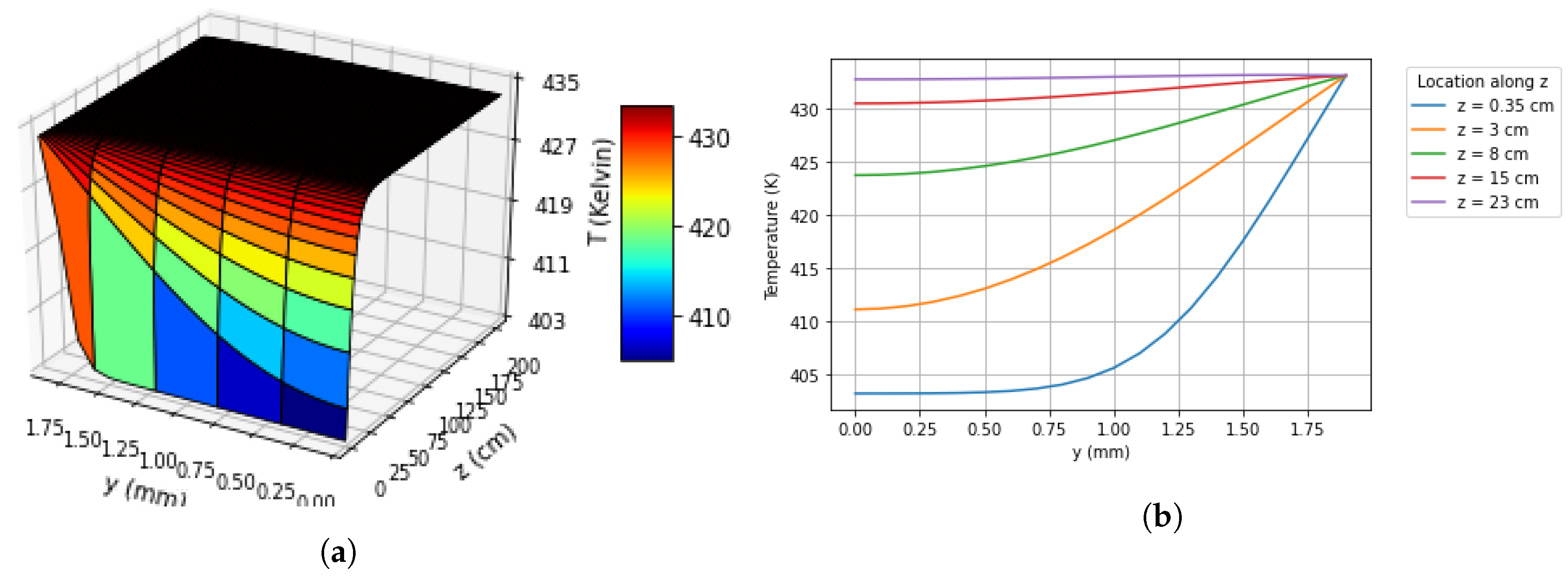
As an example, temperature results for the parallel-plate using the finite difference model were obtained for a fixed distance from the center to the wall y of 1.9 mm and the width z of 200 cm. Figure 3a presents the temperature distribution along (z) and the half of the distance (y) between parallel-plates for a case with the wall temperature ( T w a l l ) of 433.15 K and the inlet temperature ( T i n l e t ) of 403.15 K. As can be noticed, the temperature of the flow gets more evenly distributed along the y axis as z increases (See Figure 3b).
Also the analyses were conducted with the finite element model considering the 12,482 triangular elements to determine the temperature distribution along the length of the tube. As an example, Figure 4a shows the temperature distribution along the length (Z) and the radius (R) of the tube for a case with the wall temperature ( T w a l l ) of 433.15 K and inlet temperature ( T i n l e t ) of 403.15 K. The locations along the R and Z were normalized by the radius (2.2 mm) and the length (800 mm) of the tube respectively. As seen in Figure 4b, the temperature of the polypropylene melt flow gets more uniform along the direction of the R as the Z increases, and then finally reaches a steady state distribution.
The required length of parallel-plate or circular tube is defined as the length of the channel in the direction of the flow from the entrance such that the temperature of the flow reaches the steady state level. To quantify the required length of the tube ( L r e q ) to reach the steady state temperature distribution, the following criteria were used:
max T i , l + 1 T i , l T i , l < 0.001
where i = 0 , 1 , is associated with the location along R and l = 0 , 1 , is associated with the location along Z in finite element solution. When the criterion in (31) is satisfied, the steady state location along Z will be l + 1 and the required length is identified. For the example shown in Figure 4, the l is identified as 25 and the corresponding L r e q is determined as 260 mm.

4. Results and Discussion

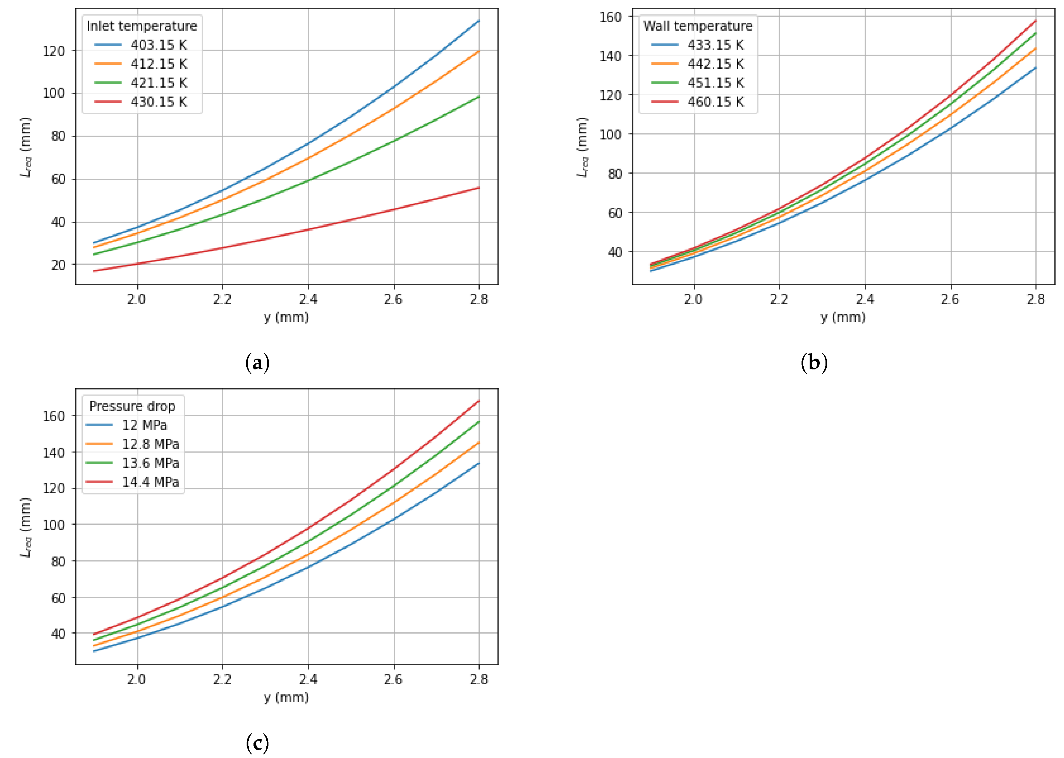
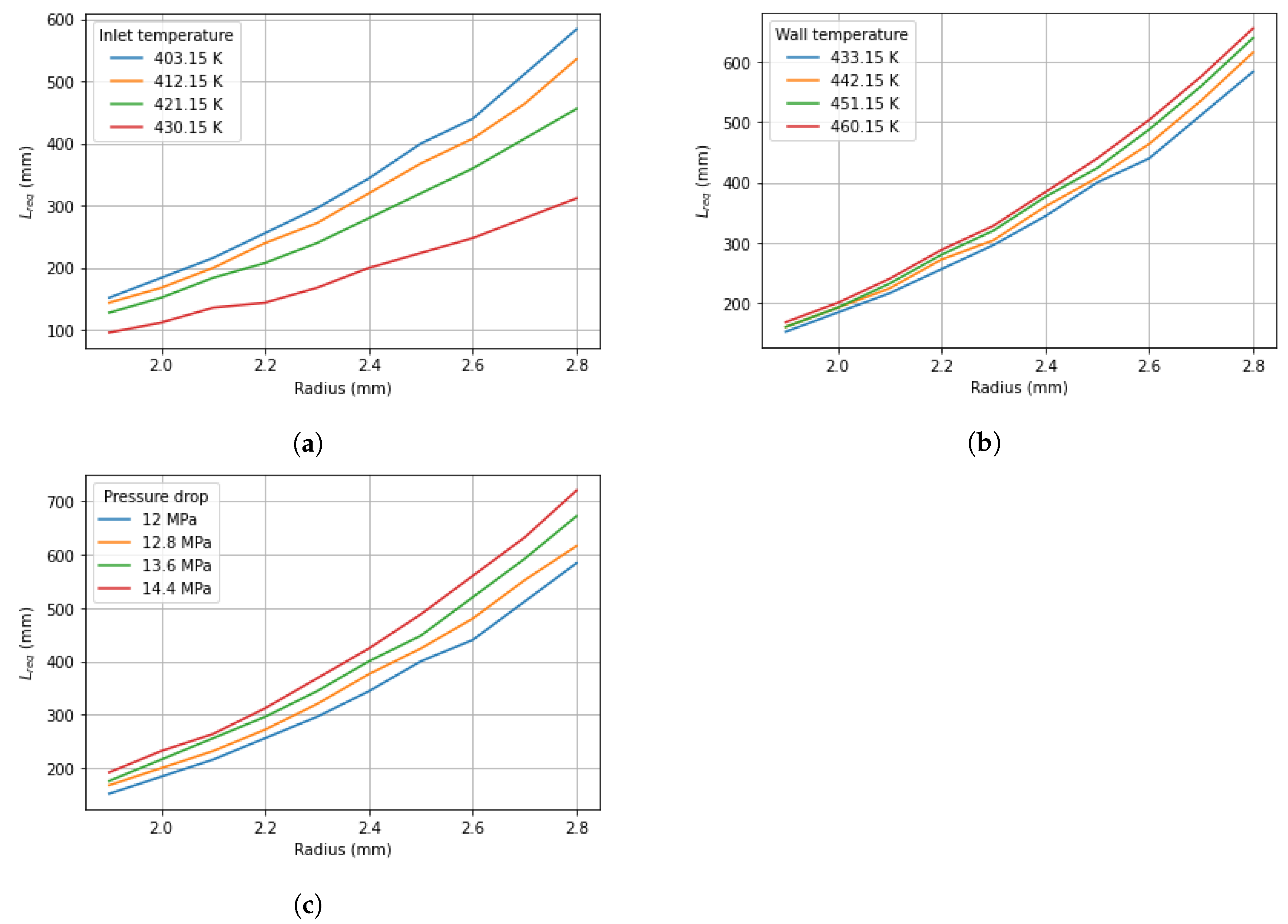
Following the same procedure, a parametric study was conducted for wall temperatures, inlet temperatures, radius of the tube, and pressure drop to determine the L r e q . Figure 5 and Figure 6 show the parametric results for the flow temperature in the parallel-plate and circular tube channels. In general, the L r e q increases as the radius of the tube increases since the larger radius can accommodate more fluid volume. As seen in Figure 5a and Figure 6a, when the inlet temperature increases and approaches the wall temperature, the L r e q becomes smaller. The explanation of this is that for the higher inlet temperature, it requires less distance for the flow temperature to reach the steady state. On the other hand (see Figure 5b and Figure 6b), as the wall temperature increases, the L r e q becomes larger since it needs more distance for the flow temperature to reach the uniform distribution. Also note, the L r e q increases when the pressure drop increases since larger pressure means higher flow speed (see Figure 5c and Figure 6c). The radius of the tube has the highest effect on the required length of the tube while other parameters have minor effects, especially for the pressure drop and the wall temperature.
It is important to note the manifolds with decreasing depth or also constant depth, which is the subject of our study. For instance, Karkri and Jarny [33] analyzed the temperature profile in the parallel-plate with constant depth using the conjugate gradient method that shows the results similar to our solutions. Another paper by Andreozzi et al. presented the temperature profile results of the fluid flows in parallel-plate systems and the authors confirmed them by the Ansys–Fluent output [34]. Their results on temperature profiles of the fluid showed similar behavior as in our results (Figure 3). As it was mentioned before, the finite element model was suitable to solve the temperature profile in a circular tube. In comparison to the solutions obtained by Wei and Luo [18], our temperature results were consistent (Figure 4).
The parametric analyses would be helpful in the designing of the extrusion die channels as these parametric study results may contribute in proper selection (for instance, radius of the tube) or controlling the parameters (i.e., wall or inlet temperature) and suggest the optimal length of the channels. Eventually, the optimal length derived from the study would assure an efficient production in which correspondingly the flow temperature is evenly distributed.

5. Conclusions

Casson rheology models were investigated for the velocity and temperature profiles, particularly, of polypropylene melt flows in extrusion die channels. Finite difference and finite element methods were used to solve for temperature distributions of the flow in the channels. The numerical model provides estimates of locations in the channels where the steady state temperature distribution is reached in Casson fluid melts. The results in the parametric study indicate that the required parallel-plate and tube lengths are highly affected by the width of the channels while other parameters (wall temperature, inlet temperature and pressure drop) have minor effects. These results can be used as a base for constructing the design of the die and increase the production efficiency of PP sheets and PP films. In addition, the numerical approach can be applied for other materials other than polypropylene, for instance, the materials that follow the Casson rheology model. Further research can be conducted by applying other rheology models such as Cross or Carreau–Yasuda for better understanding the nature of the PP flows.

Author Contributions

Conceptualization, D.W.; methodology, D.W., D.Z.; software, M.A.; validation, D.W., D.Z. and A.P.; formal analysis, D.W.; investigation, M.A.; resources, M.A.; data curation, M.A.; writing—original draft preparation, M.A.; writing—review and editing, M.A.; visualization, M.A. All authors have read and agreed to the published version of the manuscript.

Funding

This research was supported by the Nazarbayev University Research Fund under Grants # SOE2017001 and the target program No AP05134166 from the Ministry of Education and Science of the Republic of Kazakhstan. The authors are grateful for these supports. Any opinions, findings, and conclusions or recommendations expressed in this material are those of the author(s) and do not necessarily reflect the views of the Nazarbayev University or the Ministry of Education and Science of the Republic of Kazakhstan.

Acknowledgments

Special thanks to Atyrau Plastic Production Company for providing the data.

Conflicts of Interest

The authors declare no conflict of interest.

Abbreviations

Constants and variables
d P d z ,gpressure drop in the channel
η c Casson viscosity
d u d R shear rate in circular tube
d u d y shear rate in parallel-plate
D e element domain
G e boundary domain
ρ fluid density
τ shear stress
τ 0 Casson yield stress
τ w wall stress constant
C p specific heat capacity of the fluid
d 1 increment in y
d 2 increment in z
kfluid thermal conductivity
Ldistance from the inlet to exit
L r e q optimal length of the channel to reach the steady state
p i i = 1 for inlet pressure, i = 2 for pressure at exit
Qflow rate
r , R dimensional, and non-dimensional radial coordinates of the circular tube
r 0 maximum radius of the circular tube
r c critical radius of the circular tube
Ttemperature of the fluid
T i , l temperature of the fluid at y i or r i for i = 0 , 1 , , m , and at z l for l = 0 , 1 , , n
T i n l e t temperature of the fluid at the inlet
T w a l l wall temperature
uvelocity of the fluid flow
yaxis coordinate perpendicular to z in parallel-plate
y c , y c r i t critical length from the center to the critical point along y in parallel-plate
y m a x distance from the center to the wall in parallel-plate
z , Z dimensional, and non-dimensional axial coordinates in the direction of the flow
F ( e ) ,{F}local and global load vectors
K ( e ) ,Klocal and global stiffness matrices
Wvector of three linear shape functions
Superscripts and subscripts
( e ) , e evaluation of the entity referring to the particular element
pevaluation of the corresponding function at the particular point
Tmatrix transpose
JJacobian matrix

References

  1. Morris, P.J.T. Polymer Pioneers; University of Pennsylvania Press: Philadelphia, PA, USA, 1989. [Google Scholar]
  2. Razeghiyadaki, A.; Zhang, D.; Wei, D.; Perveen, A. Optimization of Polymer Extrusion Die Based on Response Surface Method. Processes 2020, 8, 1043. [Google Scholar] [CrossRef]
  3. Yilmaz, O.; Polat, Y.; Kocabas, H. Optimum Design of a Flat Coat-Hanger Die for Spunbond Nonwoven Production Process. In Proceedings of the 3rd International Scientific Conference on Engineering “Manufacturing and Advanced Technologies”, Mostar, Herzegovina, 18–20 September 2014. [Google Scholar]
  4. Maier, C.; Calafut, T. Polypropylene; William Andrew: New York, NY, USA, 1998. [Google Scholar]
  5. Igali, D.; Perveen, A.; Wei, D.; Zhang, D.; Mentbayeva, A. 3D FEM Study of the Flow Uniformity of Flat Polypropylene Film/Sheet Extrusion Dies. Key Eng. Mater. 2020, 841, 375–380. [Google Scholar] [CrossRef]
  6. NPTEL. Available online: https://nptel.ac.in/courses/112/106/112106153/ (accessed on 9 September 2020).
  7. A Guide to Polyolefin Sheet Extrusion. Available online: https://www.yumpu.com/en/document/read/11672189/a-guide-to-polyolefin-sheet-extrusion-lyondellbasell (accessed on 9 September 2020).
  8. Winter, H.H.; Fritz, H.J. Design of dies for the extrusion of sheets and annular parisons: The distribution problem. Polym. Eng. Sci. 1986, 26, 543–553. [Google Scholar] [CrossRef]
  9. Ellahi, R.; Hameed, M. Numerical analysis of steady non-Newtonian flows with heat transfer analysis, MHD and nonlinear slip effects. Int. J. Numer. Methods Heat Fluid Flow 2012, 22, 24–38. [Google Scholar] [CrossRef]
  10. Gauthier, F.; Goldsmith, H.L.; Mason, S.G. Particle motions in Non-Newtonian media. II. Poiseuille flow. Trans. Soc. Rheol. 1971, 15, 297–330. [Google Scholar] [CrossRef]
  11. Chhabra, R.P.; Richardson, J.F. Non-Newtonian Flow and Applied Rheology: Engineering Applications; Butterworth-Heinemann: Oxford, UK, 2011. [Google Scholar]
  12. Biswas, D. Blood Flow Models: A Comparative Study; Mittal Publications: Delhi, India, 2002. [Google Scholar]
  13. Rao, M.A. Rheology of Fluid and Semisolid Foods: Principles and Applications; Springer: New York, NY, USA, 2010. [Google Scholar]
  14. Karger-Kocsis, J. Polypropylene Structure; Springer: Dordrecht, The Netherlands, 2012. [Google Scholar]
  15. Wilkes, J.O. Fluid Mechanics for Chemical Engineers with Microfluidics and CFD; Pearson: London, UK, 2005; pp. 272–320. [Google Scholar]
  16. Gee, R.E.; Lyon, J.B. Nonisothermal flow of viscous non-newtonian fluids. Ind. Eng. Chem. 1957, 49, 956–960. [Google Scholar] [CrossRef]
  17. Catherine, O. A Short Review of Flow Simulation Techniques for Extrusion Die Design. In Proceedings of the SPE International Polyolefins Conference, Houston, TX, USA, 27 February 2017. [Google Scholar]
  18. Wei, D.; Luo, H. Finite element solutions of heat transfer in molten polymer flow in tubes with viscous dissipation. Int. J. Heat Mass Transf. 2003, 46, 3097–3108. [Google Scholar] [CrossRef] [Green Version]
  19. Mukhopadhyay, S. Casson fluid flow and heat transfer over a nonlinearly stretching surface. Chin. Phys. B 2013, 22, 074701. [Google Scholar] [CrossRef]
  20. Khan, M.I.; Waqas, M.; Hayat, T.; Alsaedi, A. A comparative study of Casson fluid with homogeneous-heterogeneous reactions. J. Colloid Interface Sci. 2017, 498, 85–90. [Google Scholar] [CrossRef] [PubMed]
  21. Michaelides, E.; Crowe, C.T.; Schwarzkopf, J.D. Multiphase Flow Handbook; CRC Press: Boca Raton, FL, USA, 2016. [Google Scholar]
  22. Nandy, S.K. Analytical solution of MHD stagnation-point flow and heat transfer of Casson fluid over a stretching sheet with partial slip. Int. Sch. Res. Not. 2013, 2013, 108264. [Google Scholar] [CrossRef]
  23. Ullah, I.; Alkanhal, T.A.; Shafie, S.; Nisar, K.S.; Khan, I. MHD Slip flow of Casson fluid along a nonlinear permeable stretching cylinder saturated in a porous medium with chemical reaction, viscous dissipation, and heat generation/absorption. Symmetry 2019, 11, 531. [Google Scholar] [CrossRef] [Green Version]
  24. Lungu, M.; Petrovan, S.; Rusu, M.; Apetroaiei, A.; Lungu, A. Application of rheological models for the description of the flow characteristics of some polymer systems. Acta Polym. 1992, 43, 214–218. [Google Scholar] [CrossRef]
  25. Matveenko, V.N.; Kirsanov, E.A. Structural viscosity and structural elasticity of polymer melts. Russ. J. Appl. Chem. 2018, 91, 839–865. [Google Scholar] [CrossRef]
  26. Vlachopoulos, J.; Polychronopoulos, N.D. Chapter 4: Flat Film and Sheet Dies; Smithers Rapra: London, UK, 2012. [Google Scholar]
  27. Adewale, F.J.; Lucky, A.P.; Oluwabunmi, A.P.; Boluwaji, E.F. Selecting the most appropriate model for rheological characterization of synthetic based drilling mud. Int. J. Appl. Eng. Res. 2017, 12, 7614–7629. [Google Scholar]
  28. Engineering Toolbox. Available online: https://www.engineeringtoolbox.com (accessed on 9 September 2020).
  29. Technical Data on Extrusion Dies. Available online: https://figshare.com/articles/dataset/01-Die_-_CF3-B-ETP_-_Manual_1_pdf/12981113 (accessed on 9 September 2020).
  30. Typical Engineering Properties of Polypropylene. Available online: https://www.ineos.com/globalassets/ineos-group/businesses/ineos-olefins-and-polymers-usa/products/technical-information--patents/ineos-engineering-properties-of-pp.pdf (accessed on 9 September 2020).
  31. Cebeci, T. Convective Heat Transfer; Springer: New York, NY, USA, 2002. [Google Scholar]
  32. Segerlind, L.J. Applied Finite Element Analysis; John Wiley: New York, NY, USA, 1984. [Google Scholar]
  33. Karkri, M.; Jarny, Y.; Mousseau, P. Estimation of the Initial Temperature Profile in the Channel of an Experimental Extrusion Die. In Proceedings of the 5th International Conference on Inverse Problems in Engineering: Theory and Practice, Cambridge, UK, 1–15 July 2005. [Google Scholar]
  34. Andreozzi, A.; Buonomo, B.; Pasqua, A.; Ercole, D.; Manca, O. Heat Transfer Behaviors of Parallel Plate Systems in Sensible Thermal Energy Storage. In Proceedings of the 72nd Conference of the Italian Thermal Machines Engineering Association, Lecce, Italy, 6–8 September 2017. [Google Scholar]
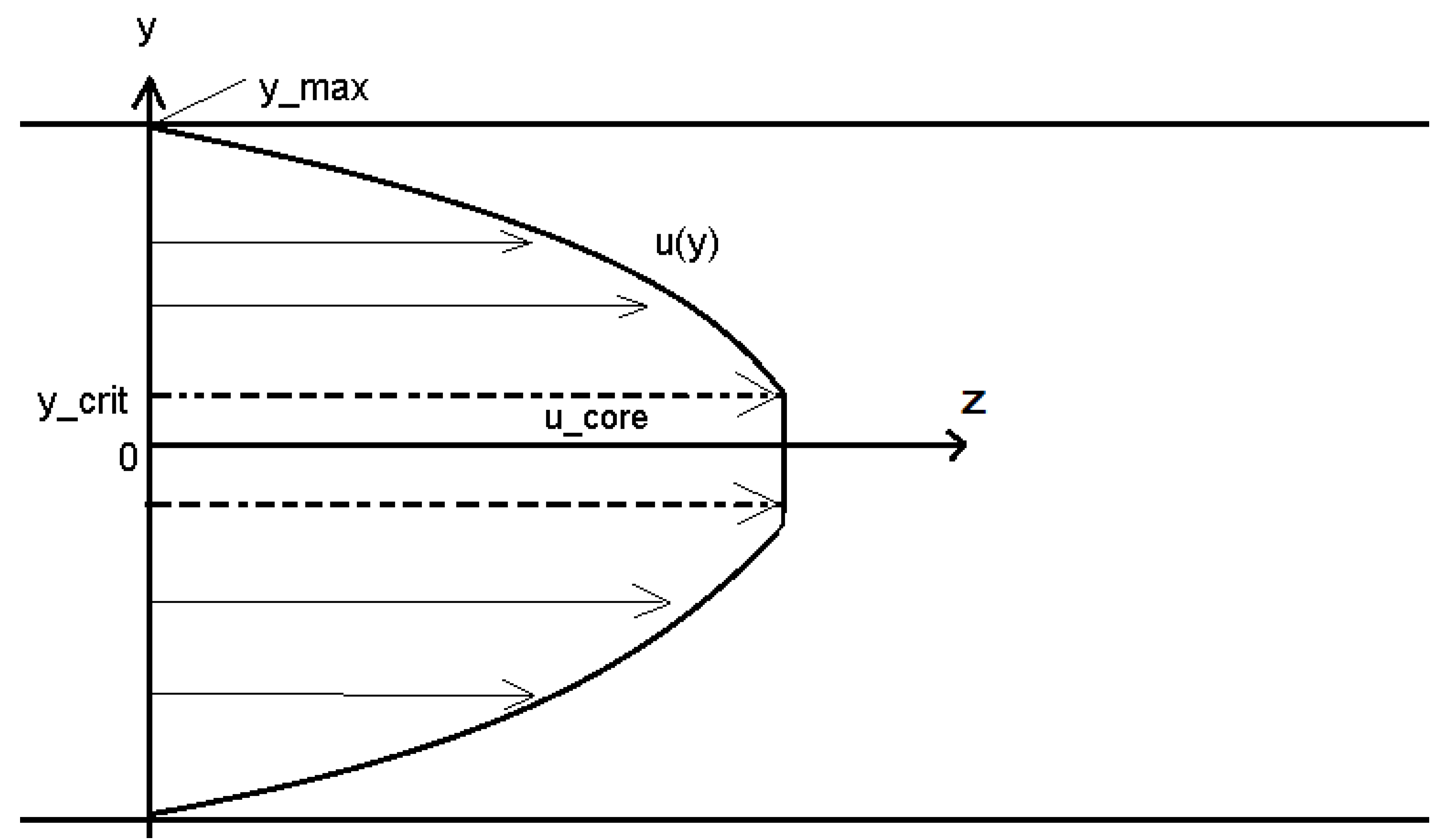
Figure 1. The Casson flow model.
Processes 08 01256 g001
Figure 2. Velocity profile of Casson flow.
Processes 08 01256 g002
Figure 3. Finite difference solutions of temperature distribution of fluid flow in parallel-plate. (a) 3D view of temperature distribution in parallel-plate; (b) temperature profile along y.
Processes 08 01256 g003
Figure 4. Finite element solutions of temperature distribution of fluid flow inside the circular tube. (a) 3D view of temperature distribution in circular tube; (b) temperature profile along R.
Processes 08 01256 g004
Figure 5. The required length of parallel-plate (Lreq) for the temperature to reach steady state vs. the distance from the center to the wall (y). (a) Various inlet temperatures; (b) various wall temperatures; (c) various pressure drop.
Processes 08 01256 g005
Figure 6. The required length of tube (Lreq) for the temperature to reach steady state vs. the radius of the tube. (a) Various inlet temperatures; (b) various wall temperatures; (c) various pressure drop.
Processes 08 01256 g006