Abstract
Microwave (MW) heating of supported metal nanoparticles (NPs) presents attractive effects on catalysis such as the rapid heating processes and the enhancement of the reaction rate. Improving the heating property of the NPs, which act as the catalytic active sites, the MW effects will become more significant. Here we show a systematic study about the supported Pt NPs structure to improve the MW heating property. We found that the drastic heating was induced by a percolated Pt NPs structure, where the conduction electrons move around in the two-dimensional network. On the other hand, no heating was observed in an isolated Pt NPs system with the confined electrons. We conclude that the percolation of the Pt NPs giving the network structure is one of the important key factors for the efficient MW heating. The optimized Pt NPs catalyst leads to the dramatic MW effects on catalytic reactions.
1. Introduction
Microwave (MW) heating processes have been applied to a lot of catalytic reactions [1,2,3,4,5,6,7,8]. In the heterogeneous gas-solid system, solid catalysts are selectively heated due to the interactions of the conduction electrons or the dipoles with MWs [1]. The local heating of the active sites brings the rapid increase in the local temperature with low energy for driving the catalytic reactions [1], whereas the temperature of the other part in the catalytic apparatus still remains lower [4]. These MW effects are a big advantage, which enables short time processes, enhancement of reaction rate, efficient energy usage and simple apparatuses without thermal insulators. The MW effects have been also observed in the supported metal nanoparticles (NPs) catalyst [9,10,11,12,13,14,15,16,17,18]. Jie et al. applied the MW heating to the catalytic system of the supported Fe NPs, where dehydrogenation at the Fe NPs was selectively driven while the side reactions were prevented [14,17]. They attributed this selective reaction progress to the local heating of the Fe NPs, and moreover, the nanoscale high temperature area was possibly formed. He et al. discussed the mechanism of the enhanced MW absorption in metal NPs due to (1) local movement of bound charges to form the interfacial dipoles, (2) surface plasmon with collective oscillation of conduction electrons and (3) near field coupling of MW electric field at the metal NPs [19]. By improving the MW heating property and the local high temperature of the supported NPs, the dramatic MW effects on catalytic reactions can be obtained.
MW heating mechanisms of the metal particles have been discussed [20,21,22,23,24]. Bulk metals have high conductivity, and they reflect MWs to prevent heating. In contrast, the powdered metals can be heated by MWs because the MWs can penetrate them to generate a lot of heat. Nano-sized thin metal layer or other two-dimensional materials are also researched well by MWs [25,26,27,28,29]. Obrzut et al. demonstrated the dielectric property of the Au NPs layer [27]. The thicker Au NPs layer with the 8~ nm thickness reflected parts of MWs, while the thinner one was transparent. Notably, the Au NPs layer exhibited the highest MW absorption property when the thickness was 8 nm. The suitable conductivity of the Au NPs layer provided the resonant interaction between the electrons and MWs, leading to the best heating property. For the isolated NPs system, there are only a few reports referring to the insight of the MW heating [30,31,32]. The supported NPs are often highly dispersed on the catalyst support that is also the isolated NPs system. However, the isolated NPs seem to have the poor heating property because the electrons are confined in the NPs [27,33]. To enhance the MW heating in the supported metal NPs catalytic system, we consider that the NPs structure should be optimized from the isolated system to the layer-like structure.
In this paper, we show a systematic study to elucidate the optimum structure of the supported metal Pt NPs catalyst on Al2O3 for the improvement in the MW heating property. Since catalyst supports generally contain the adsorbed water [34] and the defects [35], the supports are also heated by MWs, and it is tricky to evaluate the MW heating property of the Pt NPs on the supports. In contrast, Maitani et al. demonstrated the single crystal of the metal oxides were not heated at all by microwaves [36]. Then, we applied the single crystal of α-Al2O3 A-plane as support for Pt NPs. We conducted the MW heating experiments for Pt-NPs-supported α-Al2O3 substrates (Pt/Al2O3), where the Pt NPs amount was controlled to be isolated Pt NPs or layer-like Pt NPs. Moreover, the effect of the Pt NPs aggregation was also evaluated by applying further calcinations at 300–600 °C. Comparing the MW heating results of Pt/Al2O3, we elucidated the critical factor for the MW heating property of the Pt NPs. We propose the optimized structure of the supported metal NPs for the MW-driven catalytic reactions.
2. Materials and Methods
Substrates of α-Al2O3 A-plane of single crystals were purchased from Crystal Base Co., Ltd. (Osaka, Japan). The substrates were cut into the size of 5.0 mm × 5.0 mm × 0.5 mm, washed by acetone and 2-propanol, dried by N2 blow and calcined for 20 min at 600 °C on a hot plate (MSA Factory Co., Ltd., Tokyo, Japan). Then, we conducted Pt sputtering for the bare Al2O3 substrates by using an ion coater (IB-3, Eiko Co., Ltd., Osaka, Japan) with a Pt target (Eiko Co., Ltd., Osaka, Japan). As conditions, the applied voltage, current and pressure were 1400 V, 4 mA and 18 Pa, respectively. The sputtering time was controlled in 20–180 s to change the Pt NPs amount of the Pt/Al2O3 substrates. After that, the Pt/Al2O3 were calcined for 20 min at 300–600 °C on a hotplate to change the extent of the Pt NPs aggregation. The topography images of the Pt/Al2O3 surfaces were measured by AFM (Cypher S, Asylum Research, Oxford Instruments, Goleta, CA, USA). ACAFM tapping mode was applied by a cantilever (AC160TS, Olympus Co., Tokyo, Japan) with 7 nm of the tip curvature diameter.
The metallic state of the Pt NPs of the 60 s-sputtered and 300 °C-calcined Pt/Al2O3 was confirmed by applying fluorescence X-ray absorption fine structure (XAFS) spectroscopy [37]. We used BL 9C beamline at KEK-IMSS-PF (Tsukuba, Japan). The energy storage ring supplied synchrotron X-ray, and it was monochromatized by Si(111) channel-cut crystals. The angle and the energy were calibrated using Pt foil. The energy range of 11057–12662 eV was selected for incident X-ray to analyze Pt L3-edge XAFS. The ionization chamber at the incident point was filled with 15% Ar-85% N2 mixed gas for monitoring the incident X-ray. Fluorescence signals were detected with 7-elements Silicon Drift Detector (XSDD50-07, Techno AP, Ibaraki, Japan). XAFS measurements were carried out in the parallel orientation relative to the electric vector (E) of the incident X-rays. XANES spectra of the Pt foil and Na2Pt(OH)6 were also measured by detecting transmitted X-ray, where the ionization chamber was filled with 100 % Ar gas. The obtained XAFS spectra were analyzed by applying REX2000 software (Rigaku Co., Tokyo, Japan). The EXAFS spectra were k3-weighted, and then, the range of the k = 3–12 Å−1 was used to obtain the Fourier-transformed EXAFS (FT-EXAFS) spectra.
Cross-section TEM images of the Pt/Al2O3 substrates were obtained by FE-TEM (JEM-2010F, JEOL Ltd., Tokyo, Japan). The segments of 60 nm × ~10 μm × ~10 μm were prepared by FIB (JEM-9310FIB, JEOL Ltd., Tokyo, Japan) from the Pt/Al2O3 substrates of 5 mm × 5 mm × 0.5 mm, which were placed at a holder and introduced into the FE-TEM. The segment length of 60 nm enabled the incident electron beam to penetrate the segments to reach the detector. Controlling the holder angle, both of side views and oblique views were obtained. In the side view, where the electron beam was perpendicular to the cross section, the thickness of the Pt NPs layer on the Al2O3 substrates were determined. At this time, the Pt NPs images were overlapped because the electron beam penetrated the multiple Pt NPs. Changing the holder angle, the separated Pt images were observed as the oblique view. The Pt amount of the 60 s-sputtered Pt/Al2O3 was estimated as follows. A substrate of SiO2 amorphous (Crystal Base Co., Ltd., Osaka, Japan) was applied to obtain 60 s-sputtered Pt/SiO2 by the same way as the 60 s-sputtered Pt/Al2O3. The Pt/SiO2 was immersed in aqua regia to dissolve the supported Pt. The Pt solution was diluted by water, and then, the Pt solution was introduced to ICP-MS (7700x, Agilent Technology, Santa Clara, CA, USA) to determine the Pt amount of the Pt/SiO2. If the Pt/Al2O3 was applied, the Al components are also dissolved to interrupt the ICP analysis. Since the same sputtering time was applied, we considered the Pt amount of the Pt/SiO2 should be same as that of the Pt/Al2O3. Therefore, we obtained the Pt amount of the Pt/Al2O3 from the ICP-MS data of the Pt/SiO2.
MW heating experiments of the substrates were conducted in a TE103 mode resonator cavity with 2450 MHz frequency [38]. Figure 1 shows the setup; The cavity was connected to a signal generator (USG-LF44; Texio Technology Co., Kanagawa, Japan) and a function generator (AWG1005, AS ONE Corporation, Osaka, Japan) to control the MW emission and the incident power of 5 watt, and a directional coupler (ZGDC35-93HP+, Mini-Circuits, Inc. Ltd., Kanagawa, Japan) was also equipped, which introduced the incident waves and reflected waves into a cross domain analyzer (U3851, ADVANTEST Co., Tokyo, Japan) to confirm the standing wave condition in the TE103 cavity. The substrates were put at the maximum points of the electric field (E field) or the magnetic field (H field). The vibration direction of the E field was parallel to the substrate surface, and that of the H field was perpendicular. Temperatures of the substrates under MW heating were monitored by a thermo camera (G100, Nippon Avionics Co., Ltd., Tokyo, Japan). Referring to the black body, the emissivity of the substrates was experimentally-determined. The emissivity was applied to the temperature measurement under MW heating experiments. The MW heating experiments were repeated 4 times for each of the substrates.
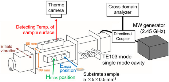
Figure 1.
Set up for microwave (MW) heating experiment with substrate sample.
3. Results and Discussions
3.1. Drastic MW Heating of Pt/Al2O3 Substrate
Figure 2 shows the temperature changes of two substrates, the 60 s-sputtered and 300 °C-heated Pt/Al2O3 substrate and the bare Al2O3 substrate under MW heating of 5 watt. The substrates were put in the E field maximum point, where the parallel vibration of the MW E field was dominant for the heating. We found that the drastic heating was induced in the Pt/Al2O3 substrate system. The temperature was increased to 240 °C by the notably-low power of 5 watt, and the temperature elevation completed in the short time as 150 s. On the other hand, without Pt, the bare Al2O3 substrate was not heated by MWs at all. We consider that the drastic heating is attributed to the Pt NPs, and then, we can evaluate the MW heating property of the Pt NPs by using the attained temperature in the MW heating experiment.
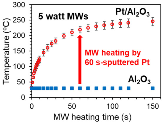
Figure 2.
MW heating of 60 s-sputtered and 300 °C-calcined Pt/Al2O3 substrate and 600 °C-calcined bare Al2O3 substrate. The substrates were put at the maximum point of electric field. Each heating experiments were repeated by 4 times to depict the error bars.
Figure 3a shows an AFM image of the Pt/Al2O3 surface. The small particles cover almost the whole area, which indicates that the Pt NPs are supported sufficiently to cover the Al2O3 surface. Root mean squared (RMS) roughness is calculated by using Equation (1):
where y is height at each point, and the RMS roughness of the Pt/Al2O3 surface was calculated as 0.3 nm. In contrast, Figure 3b shows an AFM image of the bare Al2O3 surface without Pt NPs, showing small roughness. Expanding the scanning range in the observation of the bare Al2O3, the bumps were ordered (Figure 4), which indicates the steps of the clearly-exposed Al2O3 A-plane. Since the bump images disappeared after the 60 s Pt sputtering, we consider that the Pt NPs layer was formed on the Al2O3 A-plane and the layer probably consisted of a network structure of the Pt NPs.
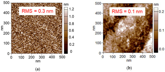
Figure 3.
AFM images of (a) 60 s-sputtered and 300 °C-calcined Pt/Al2O3 substrate and (b) bare Al2O3 substrate after 600 °C-calcination.
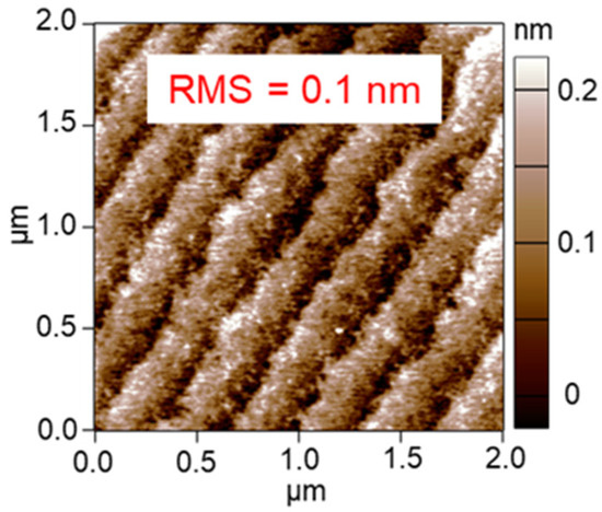
Figure 4.
Widely ranged AFM image of bare Al2O3 substrate after 600 °C-calcination.
We analyzed the oxidation state of the Pt NPs of the Pt/Al2O3 by the fluorescence XAFS spectroscopy. Figure 5a shows the XANES spectra of the Pt/Al2O3, references of Pt foil and Na2Pt(OH)6. Comparing the whiteline intensity, the XANES of the Pt/Al2O3 was similar to that of the Pt foil. Figure 5b shows the EXAFS spectrum and the range of the k = 3–12 Å−1 was used to obtain FT-EXAFS spectrum (Figure 5c). The peak around 2.7 Å was assigned to the Pt-Pt bonding of the Pt NPs, showing the metallic state of the Pt NPs [39].
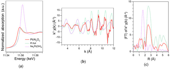
Figure 5.
XAFS spectra of the 60 s-sputtered and 300 °C-calcined Pt/Al2O3 substrate; reference samples of Pt foil and Na2Pt(OH)6. (a) XANES (b) EXAFS and (c) FT-EXAFS.
3.2. Effect of Amount of Supported Pt on MW Heating
To elucidate the optimized structure of the supported metal catalyst, the effect of the amount of the supported Pt NPs was evaluated on the MW heating at first. We conducted the MW heating experiments with the 20–180 s sputtered Pt/Al2O3 substrates. Figure 6a shows the temperature change of the Pt/Al2O3 containing the different amounts of the Pt NPs by applying MW E-field of 5 watt. While the 20 s-sputtered Pt/Al2O3 was hardly heated, the 40 s-sputtered Pt/Al2O3 was heated to 190 °C. The 60 s-sputtered Pt/Al2O3 exhibited the highest temperature as 240 °C, and then, the attained temperature got lower with the longer sputtering time among the MW experiments.
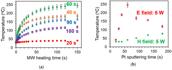
Figure 6.
MW heating of 20–180 s sputtered and 300 °C-calcined Pt/Al2O3 substrates. (a) Temperature increase by MW electric field (E field) over heating time. (b) Temperature after 150 s heating of E field or MW magnetic field (H field). Each heating experiments were repeated by 4 times.
We supposed that the network structure formed between the Pt NPs should be correlated with the extent of the MW heating on the basis of the dependence of the attained temperature on the amount of the Pt NPs. Figure 7a shows the AFM image of the 20 s-sputtered Pt/Al2O3, where the Al2O3 surface seems to be exposed. Since the amount of the Pt NPs is so small, the Pt NPs are isolated with no network, resulting in low conductivity, which was transparent against MWs. In contrast, Figure 7d shows the AFM image of the 180 s-sputtered Pt/Al2O3, where the Pt NPs covered almost the whole of the Al2O3 surface, resulting in the formation of the Pt NPs network structure with high conductivity which reflects the MWs.
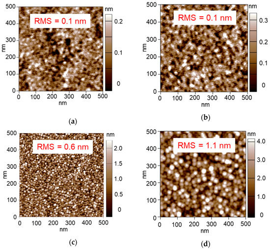
Figure 7.
AFM images of the 20–180 s sputtered and 300 °C-calcined Pt/Al2O3 substrates. (a) 20 s, (b) 40 s, (c) 90 s and (d) 180 s.
Figure 6b summarizes the attained temperatures after the 150 s heating by applying the MW E field or the MW H field. The MW E field heating presented the temperature optimum against the sputtering time; however, the attained temperature by the MW H field heating was only monotonously and gradually increased. Since MW H field is not reflected by the conductive materials [38,40], the heating property becomes enhanced with the conductivity increase [41,42]. In our results, the attained temperature was much lower under MW H fields compared to the E field condition, which indicated the E field was dominant to heat the Pt/Al2O3 substrate due to the relatively-low conductivity.
We found that the 60 s-sputtered Pt NPs exhibited the best heating property by the MW E field, where the Pt NPs formed the network structure. Obrzut et al. also demonstrated the singular MW absorption in the Au NPs layer with the thickness of 8 nm, whereas the thinner Au NPs were transparent for the MWs while the thicker ones reflected parts of MWs [27]. These results of both systems were consistent with the effective medium theory predictions in two-dimensionally percolated system [43], which indicated the conductivity of the metal NPs got drastically increased near the percolated state with two-dimensional charge transport. The electrons with the suitable conductivity exhibited the resonant interaction with MWs to generate the large heating amount [44]. Therefore, the MW heating property is theoretically-correlated with the percolation conditions of the supported metal NPs. We conclude that the amount of the supported metals is one of the key factors to determine the percolation condition, leading to the MW heating property.
3.3. Effect of Pt Aggregation on MW Heating
The supported metal NPs are often aggregated or dispersed under catalytic reactions, depending on the conditions of the temperature and the reactive gases. At the time, MW heating property can be also changed by the NPs aggregation condition. In this section, we tested the effect of the Pt NPs aggregation on the MW heating property. The 60 s-sputtered Pt/Al2O3 substrates were calcined at 450, 550, 570 and 600 °C to prepare the differently aggregated Pt NPs. The AFM images are summarized in Figure 8. Appling the 450 °C calcination, the RMS roughness was 0.2 nm (Figure 8a), which was lower than the RMS of the 300 °C-calcined substrate as 0.3 nm (Figure 3a). When calcined at 550–600 °C, the Pt NPs were obviously aggregated to show the large RMS values in 2.4–3.7 nm.
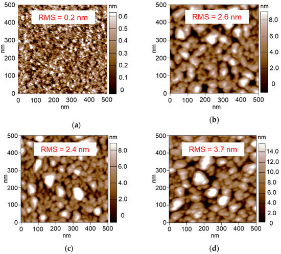
Figure 8.
AFM images of 60 s-sputtered Pt/Al2O3 substrates calcined at (a) 450 °C, (b) 550 °C, (c) 570 °C and (d) 600 °C.
To obtain more detailed information about the Pt NPs structure, we conducted the cross-section TEM analysis. Figure 9a shows a side view of the 300 °C-calcined Pt/Al2O3 substrate, where the image of the Pt NPs was observed as the densely-packed layer. Since the electron beam was perpendicular to the cross section, we estimated the thickness of the Pt NPs layer as 5.4 nm. Figure 9d shows the oblique view, where we can see each of the Pt NPs and exposed Al2O3 surface. To estimate the extent of the Pt NPs aggregation quantitatively, we calculated an apparent packing fraction of the Pt NPs () in an assumed model of 5 mm × 5 mm × H nm as the Pt NPs layer, where the H was the thickness of the Pt NPs layer observed in the TEM image. If the model is composed of close-packed Pt atoms with the packing fraction of 74% as Pt bulk metal [45], the Pt amount is calculated as 2.75 × H nmol by the following calculation; the volume of 5 mm × 5 mm × H nm is multiplied by the density of 21.45 g/cm3 [46] and divided by the molar mass of 195.1 g/mol [47]. As for the 60 s-sputtered Pt/Al2O3 substrate, the Pt NPs amount was estimated as 10.5 nmol by the ICP analysis. Therefore, the relationship between the and the H can be derived as Equation (2).
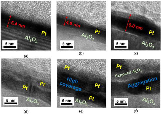
Figure 9.
Cross-section TEM images of 60 s-sputtered Pt/Al2O3 substrates calcined at 300 °C, (a) side view and (d) oblique view; those at 450 °C, (b) side view and (e) oblique view and those at 570 °C, (c) side view and (f) oblique view.
Since the H of the 300 °C-calcined Pt/Al2O3 was obtained as 5.4 nm by TEM (Figure 9a), the was calculated as 52%. Figure 9b,e indicates that the Pt NPs of the 450 °C-calcined Pt/Al2O3 were densely-packed with the H of 4.0 nm, giving the of 70%. In contrast, Figure 9c,f obviously show the Pt NPs aggregation in the 570 °C-calcined Pt/Al2O3 with the H of 8.0 nm, giving the value of 35%. The values of the RMS, the H and the are summarized in Table 1.

Table 1.
Structural property of 60 s-sputtered Pt/Al2O3 calcined at various temperature.
We conducted the MW heating experiments for the 300–600 °C-calcined Pt/Al2O3 substrates (Figure 10). Changing the calcination temperature from 300 °C to 450 °C, the attained temperature decreased from 240 °C to 180 °C. Since the value was estimated as 70% for 450 °C-calcined Pt NPs, where a lot of paths of the Pt NPs network were formed, the conduction electrons led to the high conductivity and the MWs reflection. As for the Pt/Al2O3 substrates calcined at 550 °C or 570 °C, their attained temperatures were similar to that of the 300 °C-calcined substrate. In the range of 35% to 52%, the MW heating property was not obviously changed. On the other hand, the 600 °C-calcined Pt/Al2O3 substrate was not heated at all. The large RMS value of 3.7 nm indicated the Pt NPs got highly aggregated to be larger isolated particles. Furthermore, the electrons were confined in each of the isolated Pt NPs, resulting in the less interaction between the electrons and MWs. From these results and discussions, we conclude that the extent of the Pt aggregation is directly correlated with the electronic conductivity, and the percolated Pt with the network structure is crucial for effective MW applications as the heating process (Figure 11).
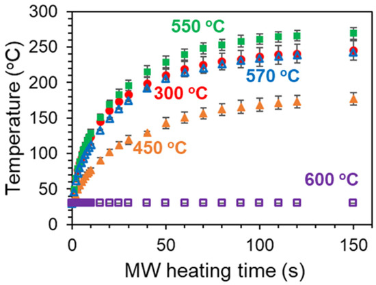
Figure 10.
MW heating of 60 s-sputtered Pt/Al2O3 substrates, which were calcined at following temperatures: 300 °C, 450 °C, 550 °C, 570 °C and 600 °C. The substrate samples were put at the maximum point of the electric field. Each heating experiment was repeated 4 times.
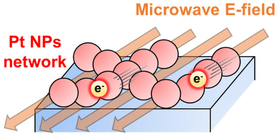
Figure 11.
Proposed mechanism of the drastic MW heating in Pt NPs network.
4. Conclusions
We demonstrated the drastic MW heating of the 60 s-sputtered and 300 °C-calcined Pt/Al2O3 substrates. The AFM image indicated that the layer-like Pt NPs covered almost the whole surface of the Al2O3 support, and the fluorescence XAFS spectra confirmed the metallic state of the Pt NPs. We considered that the percolation of the Pt NPs with the network structure was the key factor to improve the MW heating property, where the conduction electrons interacted with MWs. Moreover, we conducted the systematic study to elucidate the effect of the Pt NPs structure on the MW heating property. The Pt/Al2O3 varied in the Pt amount were prepared by changing the Pt-sputtering time. We found the singular MW absorption by the 60 s-sputtered Pt/Al2O3, which was attributed to the resonant interaction of the electrons with MWs. We also tested the effect of the Pt NPs aggregation by applying the temperature-different calcinations to the Pt/Al2O3 substrates. The moderate aggregation of the Pt NPs with the assumed packing fraction range of the 35% to 52% maintained the high MW heating property. However, the much aggregated Pt was not heated at all by MWs. From these results, we concluded that the Pt network is essential to obtain the drastic MW heating. Furthermore, the designed supported NPs catalyst can utilize the MW energy efficiently, leading to the dramatic MW effects in the catalytic systems.
Author Contributions
Conceptualization, T.A., M.M.M.; methodology, T.A., M.M.M., Y.S., validation, T.A., S.T., Y.W.; investigation, T.A.; data curation, T.A.; writing—original draft preparation, T.A.; writing—review and editing, Y.W.; visualization, T.A.; supervision, Y.W.; project administration, Y.W.; funding acquisition, T.A., M.M.M., S.T. and Y.W. All authors have read and agreed to the published version of the manuscript.
Funding
This research received no external funding.
Acknowledgments
We are grateful to W.-J. Chun (International Christian University) for the fluorescence XAFS measurements, N. Hatakeyama for preparing the TEM samples by FIB, K. Hori for the TEM analysis and Y. Ohtsuka for the ICP-MS analysis. XAFS measurement was conducted under the approval of the High Energy Accelerator Research Organization, KEK, Photon Factory Advisory Committee (2018G601). This work was supported in part by JSPS Grant-in-Aid for Scientific Research (S) 17H06156 and (C) 18K04882, JSPS Grant-in-Aid for Young Scientists (A) 17H05049 and JSPS Grant-in-Aid Fellows 17J09059 and Research Grant of TEPCO Memorial Foundation.
Conflicts of Interest
The authors declare no conflict of interest.
References
- Durka, T.; van Gerven, T.; Stankiewicz, A. Microwaves in heterogeneous gas-phase catalysis: Experimental and numerical approaches. Chem. Eng. Technol. 2009, 32, 1301–1312. [Google Scholar] [CrossRef]
- Hunt, J.; Ferrari, A.; Lita, A.; Crosswhite, M.; Ashley, B.; Stiegman, A.E. Microwave-specific enhancement of the carbon-carbon dioxide (Boudouard) reaction. J. Phys. Chem. C 2013, 117, 26871–26880. [Google Scholar] [CrossRef]
- Zhou, J.; Xu, W.; You, Z.; Wang, Z.; Luo, Y.; Gao, L.; Yin, C.; Peng, R.; Lan, L. A new type of power energy for accelerating chemical reactions: The nature of a microwave-driving force for accelerating chemical reactions. Sci. Rep. 2016, 6, 25149. [Google Scholar] [CrossRef] [PubMed]
- Ramirez, A.; Hueso, J.L.; Mallada, R.; Santamaria, J. In situ temperature measurements in microwave-heated gas-solid catalytic systems. detection of hot spots and solid-fluid temperature gradients in the ethylene epoxidation reaction. Chem. Eng. J. 2017, 316, 50–60. [Google Scholar] [CrossRef]
- Haneishi, N.; Tsubaki, S.; Maitani, M.M.; Suzuki, E.; Fujii, S.; Wada, Y. Electromagnetic and heat-transfer simulation of the catalytic dehydrogenation of ethylbenzene under microwave irradiation. Ind. Eng. Chem. Res. 2017, 56, 7685–7692. [Google Scholar] [CrossRef]
- Wada, Y.; Tsubaki, S.; Maitani, M.M.; Fujii, S.; Kishimoto, F.; Haneishi, N. Physical insight to microwave special effects: Nonequilibrium local heating and acceleration of electron transfer. J. Jpn. Pet. Inst. 2018, 61, 98–105. [Google Scholar] [CrossRef]
- Priecel, P.; Lopez-Sanchez, J.A. Advantages and limitations of microwave reactors: From chemical synthesis to the catalytic valorization of biobased chemicals. ACS Sustain. Chem. Eng. 2019, 7, 3–21. [Google Scholar] [CrossRef]
- Haneishi, N.; Tsubaki, S.; Abe, E.; Maitani, M.M.; Suzuki, E.; Fujii, S.; Fukushima, J.; Takizawa, H.; Wada, Y. Enhancement of fixed-bed flow reactions under microwave irradiation by local heating at the vicinal contact points of catalyst particles. Sci. Rep. 2019, 9, 222. [Google Scholar] [CrossRef] [PubMed]
- Zhang, X.; Hayward, D.O.; Mingos, D.M.P. Apparent equilibrium shifts and hot-spot formation for catalytic reactions induced by microwave dielectric heating. Chem. Commun. 1999, 11, 975–976. [Google Scholar] [CrossRef]
- Zhang, X.; Lee, C.S.M.; Mingos, D.M.P.; Hayward, D.O. Carbon dioxide reforming of methane with Pt catalysts using microwave dielectric heating. Catal. Lett. 2003, 88, 129–139. [Google Scholar] [CrossRef]
- Sinev, I.; Kardash, T.; Kramareva, N.; Sinev, M.; Tkachenko, O.; Kucherov, A.; Kustov, L.M. Interaction of vanadium containing catalysts with microwaves and their activation in oxidative dehydrogenation of ethane. Catal. Today 2009, 141, 300–305. [Google Scholar] [CrossRef]
- Ohnishi, T.; Kawakami, K.; Nishioka, M.; Ogura, M. Direct decomposition of NO on metal-loaded zeolites with coexistence of oxygen and water vapor under unsteady-state conditions by NO concentration and microwave rapid heating. Catal. Today 2017, 281, 566–574. [Google Scholar] [CrossRef]
- Kustov, L.M.; Tarasov, A.L.; Tkachenko, O.P.; Kapustin, G.I. Nickel-alumina catalysts in the reaction of carbon dioxide reforming of methane under thermal and microwave heating. Ind. Eng. Chem. Res. 2017, 56, 13034–13039. [Google Scholar] [CrossRef]
- Jie, X.; Gonzalez-Cortes, S.; Xiao, T.; Wang, J.; Yao, B.; Slocombe, D.R.; Al-Megren, H.A.; Dilworth, J.R.; Thomas, J.M.; Edwards, P.P. Rapid production of high-purity hydrogen fuel through microwave-promoted deep catalytic dehydrogenation of liquid alkanes with abundant metals. Angew. Chem. Int. Ed. 2017, 56, 10170–10173. [Google Scholar] [CrossRef] [PubMed]
- Guler, M.; Dogu, T.; Varisli, D. Hydrogen production over molybdenum loaded mesoporous carbon catalysts in microwave heated reactor system. Appl. Catal. B Environ. 2017, 219, 173–182. [Google Scholar] [CrossRef]
- Gangurde, L.S.; Sturm, G.S.J.; Devadiga, T.J.; Stankiewicz, A.I.; Stefanidis, G.D. Complexity and challenges in noncontact high temperature measurements in microwave-assisted catalytic reactors. Ind. Eng. Chem. Res. 2017, 56, 13379–13391. [Google Scholar] [CrossRef]
- Jie, X.; Gonzalez-Cortes, S.; Xiao, T.; Yao, B.; Wang, J.; Slocombe, D.R.; Fang, Y.; Miller, N.; Al-Megren, H.A.; Dilworth, J.R.; et al. The decarbonisation of petroleum and other fossil hydrocarbon fuels for the facile production and safe storage of hydrogen. Energy Environ. Sci. 2019, 12, 238–249. [Google Scholar] [CrossRef]
- Ramirez, A.; Hueso, J.L.; Abian, M.; Alzueta, M.U.; Mallada, R.; Santamaria, J. Escaping undesired gas-phase chemistry: Microwave-driven selectivity enhancement in heterogeneous catalytic reactors. Sci. Adv. 2019, 5, eaau9000. [Google Scholar] [CrossRef]
- He, Z.; Liu, M.; Liu, L.; Tong, G.; Wu, W.; Wang, X. Distinct plasmon resonance enhanced microwave absorption of strawberry-like Co/C/Fe/C core-shell hierarchical flowers: Via engineering the diameter and interparticle spacing of Fe/C nanoparticles. RSC Adv. 2019, 9, 22644–22655. [Google Scholar] [CrossRef]
- Marquardt, P.; Nimtz, G. Size-dependent dielectric response of small metal particles. Phys. Rev. B 1991, 43, 14245–14247. [Google Scholar] [CrossRef]
- Roy, R.; Agrawal, D.; Cheng, J.; Gedevanlshvili, S. Full sintering of powdered-metal bodies in a microwave field. Nature 1999, 399, 668–670. [Google Scholar] [CrossRef]
- Bowler, N. Designing dielectric loss at microwave frequencies using multi-layered filler particles in a composite. IEEE Trans. Dielectr. Electr. Insul. 2006, 13, 703–711. [Google Scholar] [CrossRef]
- Ignatenko, M.; Tanaka, M.; Sato, M. Absorption of microwave energy by a spherical nonmagnetic metal particle. Jpn. J. Appl. Phys. 2009, 48, 6R. [Google Scholar] [CrossRef]
- Porch, A.; Slocombe, D.; Edwards, P.P. Microwave absorption in powders of small conducting particles for heating applications. Phys. Chem. Chem. Phys. 2013, 15, 2757–2763. [Google Scholar] [CrossRef]
- Bosman, H.; Lau, Y.Y.; Gilgenbach, R.M. Microwave absorption on a thin film. Appl. Phys. Lett. 2003, 82, 1353–1355. [Google Scholar] [CrossRef]
- Wang, Z.J.; Otsuka, Y.; Cao, Z.; Yoshikawa, N.; Kokawa, H. Rapid crystallization of sol-gel-deposited lead zirconate titanate thin films by 2.45 GHz microwave irradiation. Jpn. J. Appl. Phys. 2008, 47, 7519–7522. [Google Scholar] [CrossRef]
- Obrzut, J.; Douglas, J.F.; Kirillov, O.; Sharifi, F.; Liddle, J.A. Resonant microwave absorption in thermally deposited Au Nanoparticle films near percolation coverage. Langmuir 2013, 29, 9010–9015. [Google Scholar] [CrossRef]
- Jia, Z.; Lan, D.; Lin, K.; Qin, M.; Kou, K.; Wu, G.; Wu, H. Progress in Low-frequency microwave absorbing materials. J. Mater. Sci. Mater. Electron. 2018, 29, 17122–17136. [Google Scholar] [CrossRef]
- Cao, M.S.; Shu, J.C.; Wang, X.X.; Wang, X.; Zhang, M.; Yang, H.J.; Fang, X.Y.; Yuan, J. Electronic structure and electromagnetic properties for 2D electromagnetic functional materials in gigahertz frequency. Ann. Phys. 2019, 531, 1–31. [Google Scholar] [CrossRef]
- Gracia, J.; Escuin, M.; Mallada, R.; Navascues, N.; Santamaria, J. Nano-heaters: New insights on the outstanding deposition of dielectric energy on perovskite nanoparticles. Nano Energy 2016, 20, 20–28. [Google Scholar] [CrossRef]
- Ashley, B.; Vakil, P.N.; Lynch, B.B.; Dyer, C.M.; Tracy, J.B.; Owens, J.; Strouse, G.F. Microwave enhancement of autocatalytic growth of nanometals. ACS Nano 2017, 11, 9957–9967. [Google Scholar] [CrossRef] [PubMed]
- Ashley, B.; Dyer, C.M.; Owens, J.; Strouse, G.F. Influence of microwave frequency and power on nanometal growth. J. Phys. Chem. C 2018, 122, 3617–3627. [Google Scholar] [CrossRef]
- Hanson, G.W.; Monreal, R.C.; Apell, S.P. Electromagnetic absorption mechanisms in metal nanospheres: Bulk and surface effects in radiofrequency-terahertz heating of nanoparticles. J. Appl. Phys. 2011, 109, 124306. [Google Scholar] [CrossRef]
- Cherbański, R.; Molga, E. Intensification of desorption processes by use of microwaves-an overview of possible applications and industrial perspectives. Chem. Eng. Process. Process Intensif. 2009, 48, 48–58. [Google Scholar] [CrossRef]
- Liu, X.; Wang, L.S.; Ma, Y.; Zheng, H.; Lin, L.; Zhang, Q.; Chen, Y.; Qiu, Y.; Peng, D.L. Enhanced microwave absorption properties by tuning cation deficiency of perovskite oxides of two-dimensional LaFeO3/C composite in X-Band. ACS Appl. Mater. Interfaces 2017, 9, 7601–7610. [Google Scholar] [CrossRef] [PubMed]
- Maitani, M.M.; Inoue, T.; Tsukushi, Y.; Hansen, N.D.J.; Mochizuki, D.; Suzuki, E.; Wada, Y. Collaborational effect of heterolytic layered configuration for enhancement of microwave heating. Chem. Commun. 2013, 49, 10841–10843. [Google Scholar] [CrossRef]
- Takakusagi, S.; Nojima, H.; Ariga, H.; Uehara, H.; Miyazaki, K.; Chun, W.J.; Iwasawa, Y.; Asakura, K. Fine tuning and orientation control of surface Cu complexes on TiO2(110) premodified with mercapto compounds: The effect of different mercapto group positions. Phys. Chem. Chem. Phys. 2013, 15, 14080–14088. [Google Scholar] [CrossRef]
- Fujii, S.; Kawamura, S.; Mochizuki, D.; Maitani, M.M.; Suzuki, E.; Wada, Y. Microwave sintering of Ag-nanoparticle thin films on a polyimide substrate. AIP Adv. 2015, 5. [Google Scholar] [CrossRef]
- Gänzler, A.M.; Casapu, M.; Vernoux, P.; Loridant, S.; Cadete Santos Aires, F.J.; Epicier, T.; Betz, B.; Hoyer, R.; Grunwaldt, J.D. Tuning the structure of platinum particles on ceria in situ for enhancing the catalytic performance of exhaust gas catalysts. Angew. Chem. Int. Ed. 2017, 56, 13078–13082. [Google Scholar] [CrossRef]
- Yoshikawa, N.; Ishizuka, E.; Taniguchi, S. Heating of metal particles in a single-mode microwave applicator. Mater. Trans. 2006, 47, 898–902. [Google Scholar] [CrossRef]
- Wen, F.; Yi, H.; Qiao, L.; Zheng, H.; Zhou, D.; Li, F. Analyses on double resonance behavior in microwave magnetic permeability of multiwalled carbon nanotube composites containing Ni catalyst. Appl. Phys. Lett. 2008, 92, 1–4. [Google Scholar] [CrossRef]
- Green, M.; Chen, X. Recent progress of nanomaterials for microwave absorption. J. Mater. 2019, 5, 503–541. [Google Scholar] [CrossRef]
- McLachlan, D.S.; Sauti, G.; Chiteme, C. Static dielectric function and scaling of the ac conductivity for universal and nonuniversal percolation systems. Phys. Rev. B Cover. Condens. Matter Mater. Phys. 2007, 76, 11–13. [Google Scholar] [CrossRef]
- Yoshikawa, N.; Kawahira, K.; Saito, Y.; Todoroki, H.; Taniguchi, S. Estimation of microwave penetration distance and complex permittivity of graphite by measurement of permittivity and direct current conductivity of graphite powder mixtures. J. Appl. Phys. 2015, 117, 084105. [Google Scholar] [CrossRef]
- Tian, N.; Zhou, Z.Y.; Sun, S.G. Platinum metal catalysts of high-index surfaces: From single-crystal planes to electrochemically shape-controlled nanoparticles. J. Phys. Chem. C 2008, 112, 19801–19817. [Google Scholar] [CrossRef]
- Dolatshahi-Pirouz, A.; Hovgaard, M.B.; Rechendorff, K.; Chevallier, J.; Foss, M.; Besenbacher, F. Scaling behavior of the surface roughness of platinum films grown by oblique angle deposition. Phys. Rev. B Cover. Condens. Matter Mater. Phys. 2008, 77, 1–5. [Google Scholar] [CrossRef]
- Griffith, W.P. The group VIII platinum-group metals and the Periodic table. Found. Chem. 2010, 12, 17–25. [Google Scholar] [CrossRef]
© 2020 by the authors. Licensee MDPI, Basel, Switzerland. This article is an open access article distributed under the terms and conditions of the Creative Commons Attribution (CC BY) license (http://creativecommons.org/licenses/by/4.0/).