Article

Numerical Study on the Influence of Inlet Guide Vanes on the Internal Flow Characteristics of Centrifugal Pump

1
Key Laboratory of Fluid Transmission Technology of Zhejiang Province, Zhejiang Sci-Tech University, Hangzhou 310018, China
2
Xi’an Aerospace Propulsion Institute, China Aerospace Science and Technology Corporation, Xi’an 710100, China
*
Author to whom correspondence should be addressed.
Processes 2020, 8(1), 122; https://doi.org/10.3390/pr8010122
Submission received: 25 December 2019 / Revised: 12 January 2020 / Accepted: 14 January 2020 / Published: 17 January 2020

Abstract

:
In order to make the centrifugal pump run efficiently and stably under various working conditions, the influences of the incoming vortex flow in the inlet pipe on the main flow in the impeller is studied numerically, based on the k ω SST turbulence model. Some guide vanes with different offset angle were added to change the statistical characteristic of the internal flow in the inlet pipe of the centrifugal pump. Both contour distributions of internal flow and statistical results of external performance are obtained and analyzed. The results show that the existence of vanes can divide the large vortex because of the reversed flow from the rotating impeller at low flow rate conditions into small vortices, which are easier to dissipate, make the velocity and pressure distribution more uniform, improve the stability of the flow in the impeller, reduce the hydraulic loss, and improve the hydraulic performance of the pump. The pump with vanes of offset angle 25° has a small pressure pulsation amplitude at each monitoring point. Comparing with the performance of the original pump, the head increased by around 2% and efficiency increased by around 2.5% of the pump with vanes of offset angle 25°.

1. Introduction

As a type of fluid machine that can efficiently convert the mechanical energy of the prime mover into the fluid kinetic energy and pressure potential energy, the pump is widely used in chemical industry, energy, agriculture, water conservancy, and petroleum industry [1,2,3]. However, the centrifugal pump cannot always keep stability under various operating conditions such as different water levels, flow rates, and rotation speeds. Meanwhile, there are many uncertain events that may lead the centrifugal pump to be unstable [4,5,6]. Therefore, numerous ways have been proposed to ensure the centrifugal pump’s efficiency and stability [7,8,9].
As early as the 1950s, the method of adjusting working conditions of the impeller machinery such as centrifugal compressors, fans, and turbines by adding inlet guide vanes had been widely used. In 2006, Xiao Jun [10] et al. conducted a performance analysis study on centrifugal compressor with adjustable guide vanes. The research showed that the performance curve moves to the small flow area when the offset is positive; when the offset is negative, the performance curve moves to the large flow area and the optimal efficiency point drops rapidly. Zhou Rui [11] analyzed the influence of the front guide vane on the performance of the axial flow pump. The results showed that the external characteristic curve of the axial flow pump could be effectively changed after changing the placement angle of the front guide vane. Wang Jian et al. [12] carried out a three-dimensional full flow numerical calculation on a low specific-speed centrifugal pump with a built-in baffle in the suction chamber. The results showed that the amplitude of pressure pulsation in each section of the volute was weakened when there was a built-in baffle, the amplitude of radial force acting on the impeller was decreased, and the axial force was obviously weakened. Coppinger [13] studied the influence of variable inlet guide vanes on industrial centrifugal compressors through experimental verification and numerical simulation techniques. The analysis of guide vanes with an angle ranging from −20° to +80°showed that a large angle setting would result in a large pressure loss, which would lead to a decrease in the efficiency of the whole system, and one appropriate guide vane angle would have a significant effect on expanding the stable operation range of the compressor.
In this paper, as a working condition adjustment method widely used in other fluid machinery, the inlet guide vane is going to be introduced into the centrifugal pump to adjust the flow distribution in an inlet pipe, aiming to improve the internal flow pattern and the hydraulic performance of the centrifugal pump. The influence of inlet guide vanes on the flow characteristics of a centrifugal pump will be studied numerically; a suggestion of inlet guide vane’s pre-selection angle of centrifugal pump will be provided to improve the working condition and ensure the long-term efficiency and stability of the centrifugal pump.

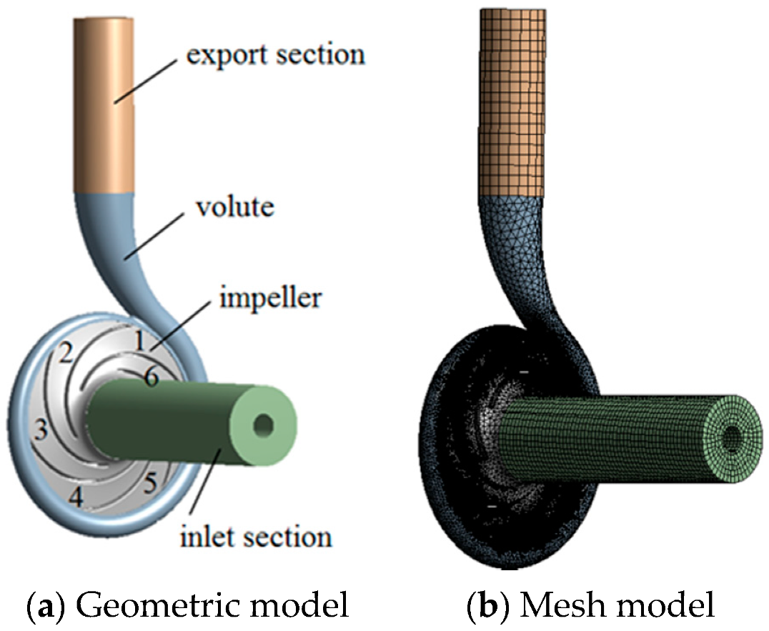
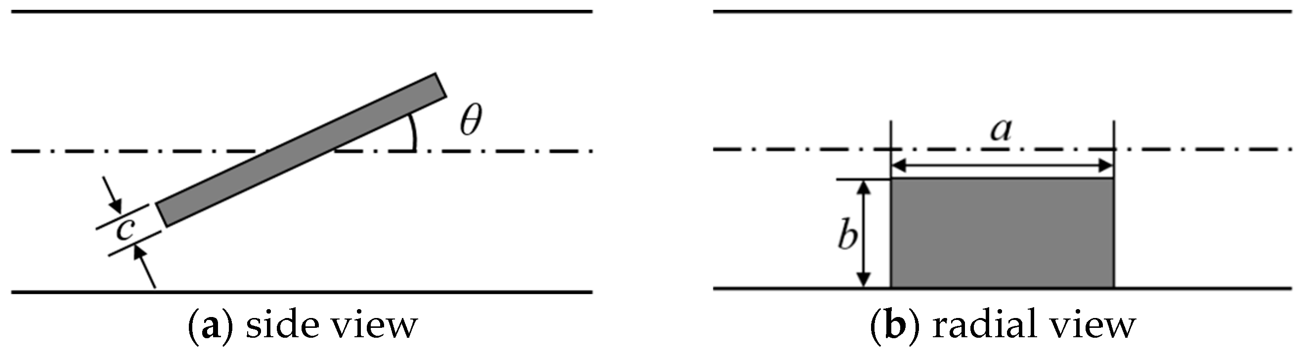
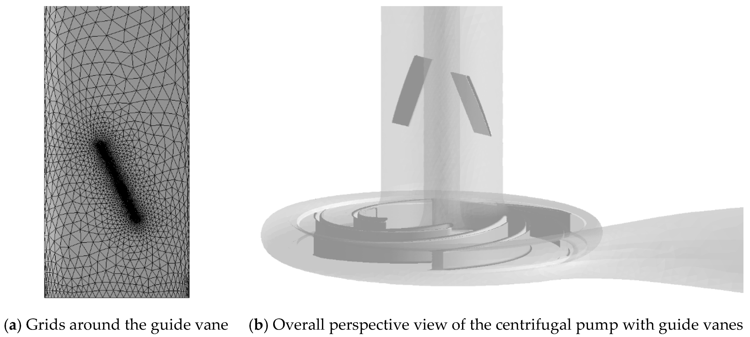
2. Calculating Models and Methods

The centrifugal pump selected in the numerical simulation is a single-stage commercial pump. The main design parameters of the centrifugal pump are shown in Table 1.
The three-dimensional modeling software Pro/E was used to model the pump, and two cylindrical extensions were added to the impeller inlet and the volute outlet, respectively. The overall flow of the centrifugal pump model consists of four parts, which are named as the inlet section, the impeller, the volute, and the outlet section, just like in other literatures [14,15]. The geometric and mesh models of the pump are shown in Figure 1.
Two symmetrical inlet straight thick guide vanes were arranged in the inlet section of the centrifugal pump; the schematic diagram of the guide vanes is shown in Figure 2. The length of the vane a is 40 mm, the width b is 50 mm, the thickness c is 2 mm, the distance of the vane from the impeller inlet is 60 mm, and the offset angle between the vane and the axial direction is θ.
A non-structural tetrahedral grid was used to mesh the inlet section of the pump with guide vanes. Grids around the guide vane were properly refined to improve the accuracy of the numerical simulation [16,17]. The grid diagram of the inlet guide vane wall surface and the overall perspective view of centrifugal pump with inlet guide vanes are shown in Figure 3.
Among the two-equation turbulence models, the k ε turbulence model can better simulate the turbulent flow that is fully developed away from the wall surface. The k ω turbulence model has a wider application to solve the boundary layer involved in problems under various pressure gradients and is widely recognized in engineering [18,19,20]. The control equations are as follows:
k equation:
( ρ k ) t + x j ( ρ U j k ) = x j [ ( μ + μ t σ k ) k x j ] + P k β ρ k ω + P k b
ω equation:
( ρ ω ) t + x j ( ρ U j ω ) = x j [ ( μ + μ t σ ω ) ω x j ] + α ω k P k β ρ ω 2 + P ω b
P is the turbulence generation rate; β , α , β , σ k , σ ω are empirical model parameters, β = 0.09 , α = 5 / 9 , β = 0.075 , σ k = 2 , σ ω = 2 .

3. Result Analysis

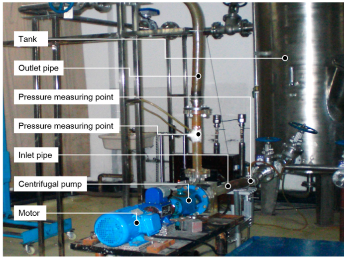
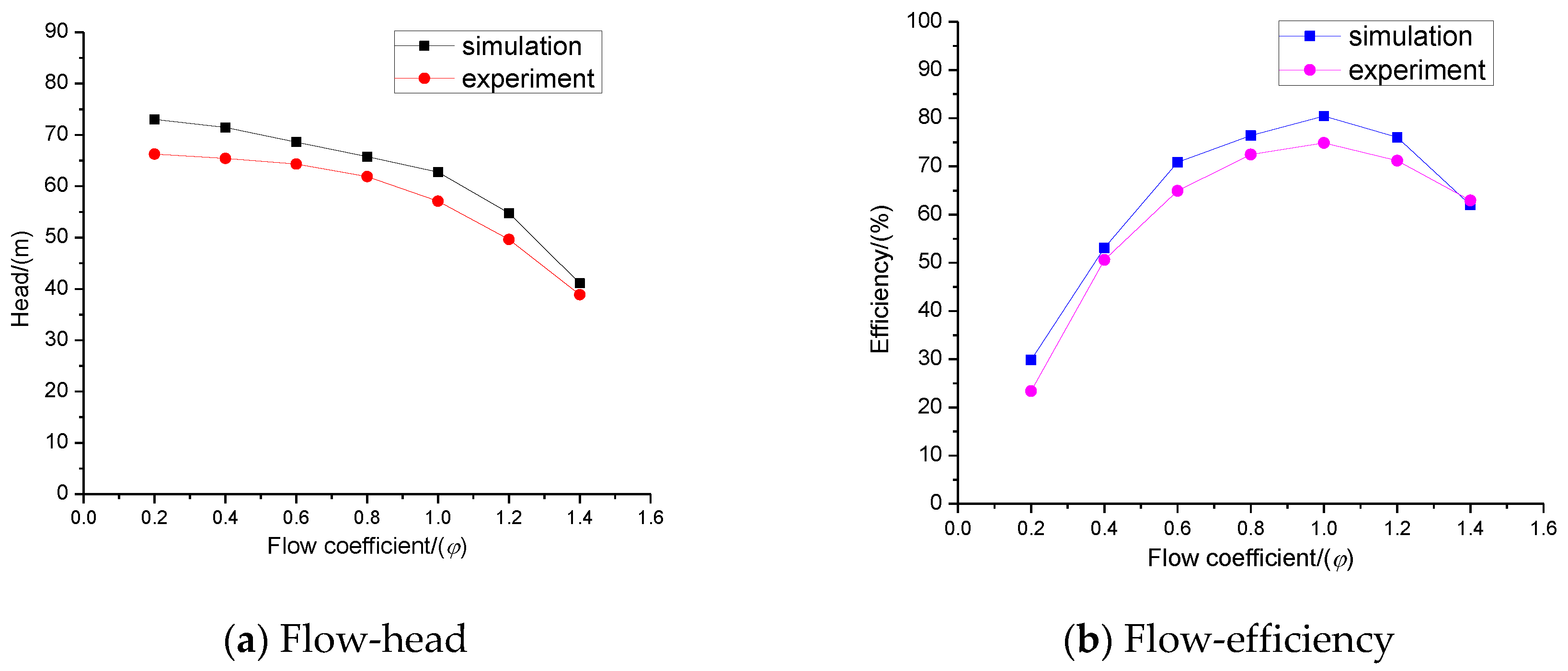
3.1. Method Validation

It is necessary to verify the independence of the centrifugal pump grid [21,22,23]. Generally speaking, if the geometry model is correctly meshed, the Reynolds-Average Navier-Stokes-based turbulence simulation result will not fluctuate significantly as the number of model grids increases. On the other hand, the centrifugal pump head is usually the most interesting parameter so it can be regarded as a reliable reference standard for the grid independence evaluation. Therefore, four sets of grids with different total grid numbers (1.2 million, 1.8 million, 2.7 million, and 4.1 million) were adopted to conduct steady numerical simulation under a design flow condition of the centrifugal pump. Different centrifugal pump heads based on these four sets of grids are given in Table 2. The result shows that all the deviations are within 0.5%. Taking the factors such as saving computing resources and computing time into account, the third grid was finally selected.
The accuracy and reliability of the numerical method were verified as well by comparing simulation pumps head and efficiency with experiment results under different flow rates. The test rig is shown in Figure 4. The simulation and experiment results are shown in Figure 5. In order to simplify the experiment and calculation, a dimensionless flow parameter was selected as the horizontal axis, represented by the flow coefficient φ. Its definition is:
φ = Flow rate Design flow rate
It can be seen that errors between the experimental value and the simulation value about the pump’s head and efficiency under different flow rates are mostly within 10%, so the effectiveness of the calculation model and method can be proved, which can be used for subsequent numerical analysis.

3.2. Flow Field Analysis of Inlet Pipelines

When the centrifugal pump is working, it is easy to generate backflow at the inlet of the impeller under the condition of a small flow rate [17,24,25]. When the backflow occurs, the fluid from the rotating impeller interacts with the incoming fluid and transfers the rotating energy to the incoming fluid, leading to the appearance of a vortex in the inlet pipe. In order to study the vortex phenomenon in the inlet pipe and the effect of the inlet guide vanes on flow state, a widely used Q criterion was adopted as the flow characterization method to analyze the vortex appearing in the inlet pipe, which characterizes the flow. Q criterion was proposed by Hunt et al. [26] in 1988 and defined the region of the second matrix invariant Q of the velocity gradient tensor ∇V in the flow field with a positive value as a vortex. In addition, it requires that the pressure in the vortex region is lower than the pressure in the surrounding flow field. For incompressible fluids:
Strain rate tensor
S i j = 1 2 ( u i x j + u j x i )
Vorticity
Ω i j = 1 2 ( u i x j u j x i )
Q value
Q = 1 2 ( Ω 2 S 2 )
Simplified to cartesian coordinate
Q = 1 2 ( ( u x ) 2 + ( v y ) 2 + ( w z ) 2 ) u y v x u z w x v z w y
Figure 6 shows the numerical distribution of the Q criterion in the inlet section near the inlet guide vane. The x-axis is the ratio of the length L of the monitoring point to the inlet of the impeller and the radius of the inlet pipe section R. It can be seen from the figure that in the inlet of the pump without guide vanes, under three small flow conditions of 0.2Qd, 0.4Qd and 0.6Qd, the Q criterion values are relatively large where the locations are close to the impeller, indicating that a vortex appears in the inlet section. As the flow rate decreases, the area where the vortex of the inlet pipe section appears gradually expands. The strength of the vortex also increases with the decrease of flow rate, which greatly blocks the main flow of the fluid. Compared with the result in the inlet section of the pump without guide vanes, vortices in the guide vane pump, under the conditions of small flow of 0.2Qd, 0.4Qd, and 0.6Qd, are closer to the impeller, and the strength of the vortex structure is smaller too. This shows that with the effects of inlet guide vanes, the position of the vortex structure can be moved toward the impeller, the strength of the vortex is weakened, and the flow blockage in the inlet pipe section can be reduced.

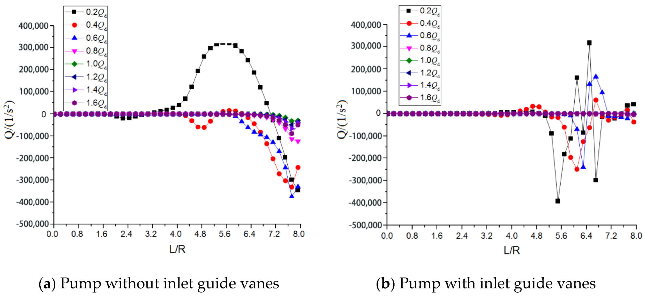
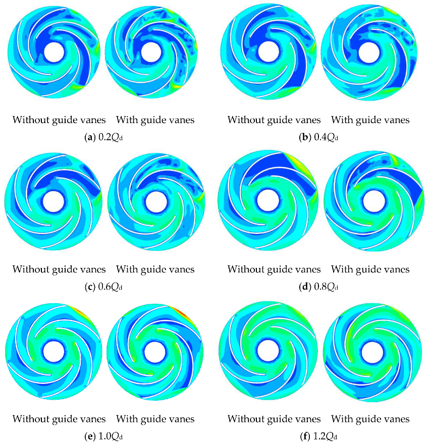
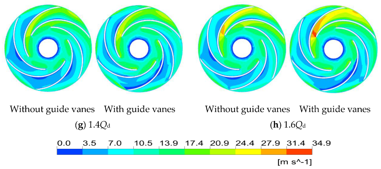
3.3. Impeller Flow Field Analysis

In order to study the distribution of physical quantities such as velocity and pressure of the centrifugal pump along the circumferential direction and the volute section, the angular distributions and the cross-sectional distributions of the volute section are shown in Figure 7.
Figure 8 shows the cross-sectional velocity distribution of the centrifugal pump impeller. The position of each flow passage of the centrifugal pump impeller is shown in Figure 7. In order to study the influence of the inlet guide vane on the fluid velocity distribution in the impeller flow passage of the centrifugal pump, we analyzed the internal flow of the impeller at the operating point of 0.2Qd ~ 1.6Qd. The various working conditions of the inlet guide vanes were compared, and the velocity distribution of the impeller section was analyzed. It can be seen from the figure that at the design operating point of 1.0Qd, the internal velocity distribution of the centrifugal pump impeller without the inlet guide vanes is good, and the blade pressure surface velocity distribution is relatively regular. The velocity distribution of the flow path away from the tongue portion in the pump with guide vanes is similar to the centrifugal pump velocity distribution without guide vanes, and a large low-speed zone appears at the flow path 6 near the tongue. This is because the flow state of the centrifugal pump is good when the centrifugal pump is working at the design condition, and the presence of the vanes has a certain disturbing effect on the flow of the fluid inside the centrifugal pump. At the working point of a high flow rate such as 1.2Qd ~ 1.6Qd, the low-speed zone of an impeller pressure surface is small at the blade path near the tongue. With the increasing flow rate, the local high-speed zone appears in blade path 1 near the tongue. When the flow rate reaches 1.6Qd, the high-speed zone inside the blade path reaches the maximum; compared with the pump without guide vanes, the pump with inlet guide vanes has a larger area in the low-speed zone of flow channel 4, and in other channels, the velocity distribution in the impeller of the pump with and without inlet guide vanes is basically the same. At low flow conditions such as 0.2Qd ~ 0.8Qd, in blade path 1, 2, 5, and blade path 6 near the tongue, the centrifugal pump with and without inlet guide vanes has a large area of low speed. The dynamic and static interference between the tongue and the impeller gradually increases with the decreasing flow rate. The low-speed zone in the impeller blade path gradually extends from the blade path near the tongue to the other blade path, and the flow of liquid flow in the blade path is seriously blocked. At the 0.2Qd operating point, the area of the low-speed zone in the entire impeller flow path is the largest. At the low flow operating point, the area of the low-velocity zone of the centrifugal pump with the inlet vane in the flow channel near the tongue portion is smaller than the area of the low-velocity zone of centrifugal pump without the inlet guide vane, and the presence of the inlet guide vanes has a certain inhibitory effect on the low-velocity region of the impeller blade path under low flow conditions. Through the analysis of the velocity field of the section in the impeller, it can be seen that under the small flow condition, the internal flow field of the impeller becomes turbulent with the decrease of the flow rate, and the area of the low-speed area generated in the impeller flow path gradually expands with the decrease of the flow rate, blocking the flow in the impeller flow channel, significantly affecting the flow capability of the impeller and increasing the hydraulic loss; compared with the centrifugal pump without inlet guide vanes, the low-speed area of the impeller passage with inlet guide vanes is smaller in the impeller passage under the condition of low flow, which can improve the flow state of the impeller passage to some extent, enhance the flow capacity of the impeller, and reduce the hydraulic loss of the centrifugal pump under the condition of low flow. At the design condition point and the large flow condition point, the existence of the vane will have a certain disturbance effect on the impeller flow field, and the area of the low-speed area in the flow channel is increased.
Figure 9 is a plot of the turbulent kinetic energy distribution of the exit section in the impeller. It can be seen from the figure that the magnitude of the change in the turbulent energy decreases as the flow rate increases. Under various working conditions, the turbulent energy value near the tongue is abruptly changed. This is the result of strong kinetic and static interference between the impeller and the volute. The turbulent flow of the fluid here is the most intense, and it is also the area with large energy loss. In the 0.2Qd and 0.4Qd operating conditions, where the value of the turbulent kinetic energy is large, it appears in the circumferential angle of 60° to 180°, compared with other operating conditions, where there are large turbulent energy values in the 0.2Qd and 0.4Qd operating conditions. At the 0.2Qd operating point, there is a larger value of the turbulent energy in the tongue region compared to the pump without guide vanes. In the 0.4Qd to 0.8Qd operating point, the value of the turbulent kinetic energy is in the range of 60° to 120° in the circumferential angle. The value of the turbulent kinetic energy of the pump with guide vanes in this area is smaller than that pump without guide vanes, and the kinetic energy value has a small amplitude of oscillation in the tongue area. At the design operating point of 1.0Qd, the distribution law of the turbulent kinetic energy of the pump with guide vanes and the pump without guide vanes is similar, but the overall value of the turbulent kinetic energy of the pump with guide vanes is larger than that of the pump without guide vanes. At the 1.2Qd ~ 1.6Qd operating point, there is no significant difference in the turbulent kinetic energy distribution between the pump with guide vanes and the pump without guide vanes at the impeller outlet. According to the above analysis, the inlet guide vanes have a significant effect on the turbulent kinetic energy of the cross-section outlets of the three small flow conditions of 0.4Qd, 0.6Qd and 0.8Qd.

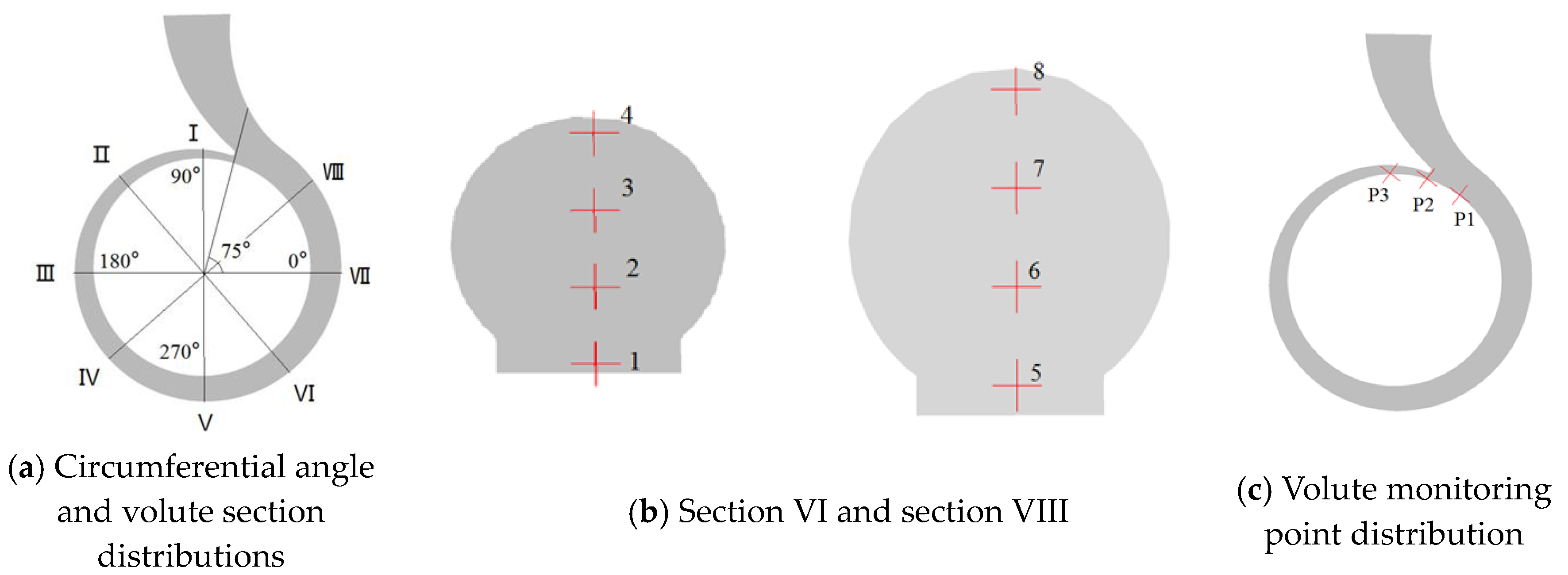
3.4. Volute Flow Field Analysis

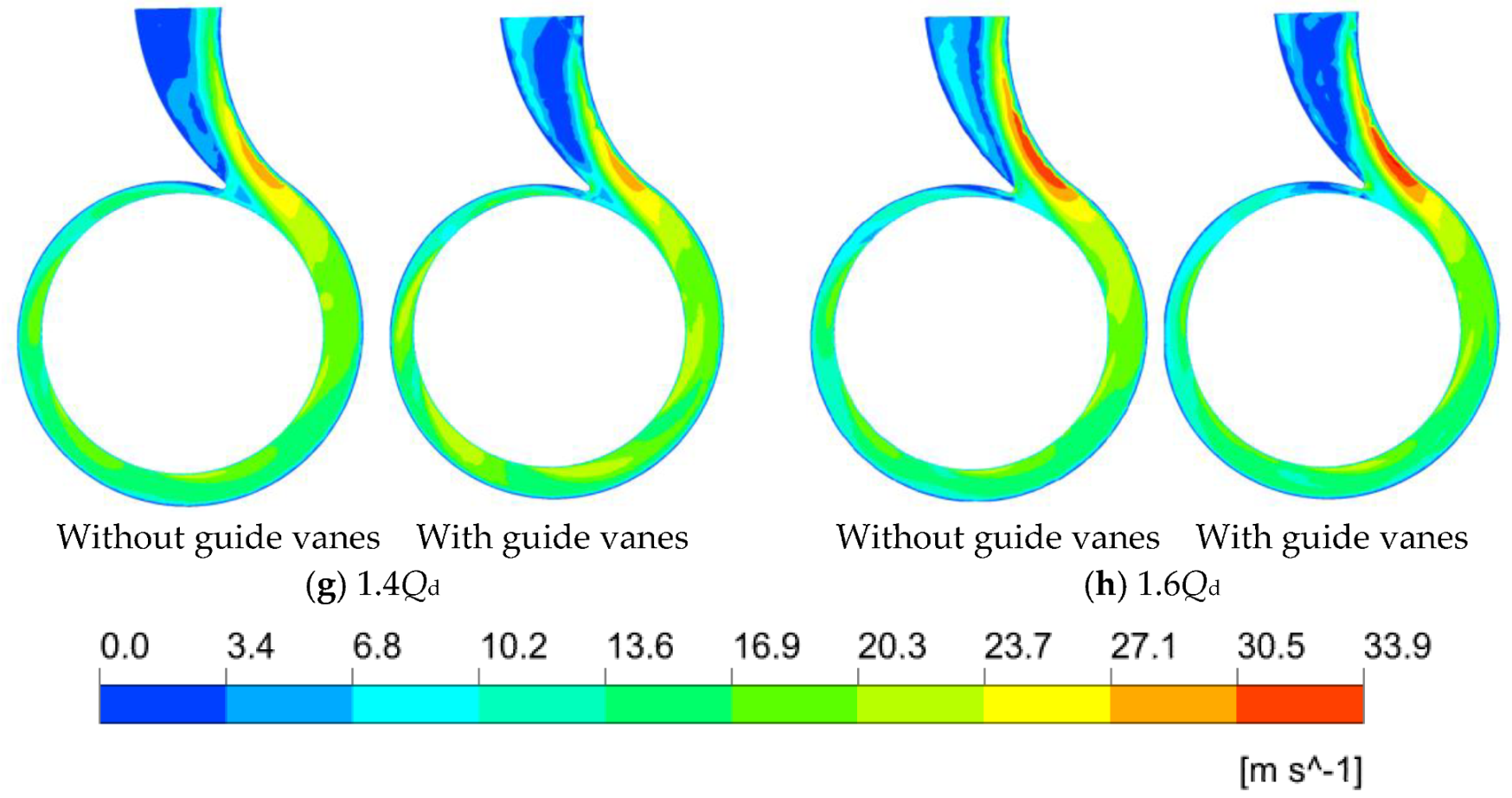
3.4.1. Velocity Analysis

The section velocity contours in the volute are shown in Figure 10. As can be seen from the figure, the flow velocity in the diffusion section of the volute is small in each flow condition, and the flow velocity continues to decrease with the gradual decrease of the flow rate, while the area of the low speed zone gradually increases, so does the hydraulic loss of the fluid in the diffusion section of the volute. The flow velocity in the spiral section of the volute is relatively high. Compared to the pump without guide vanes, the pump with guide vanes has a relatively high velocity at small flow conditions such as 0.2Qd, 0.4Qd, 0.6Qd, and 0.8Qd, and a relatively high velocity at the outlet of the impeller near the tongue. At flow conditions such as 1.0Qd, 1.2Qd, 1.4Qd, and 1.6Qd, the velocity distribution in the diffusion section and spiral section of the volute is basically the same, which is less affected by the guide vane.

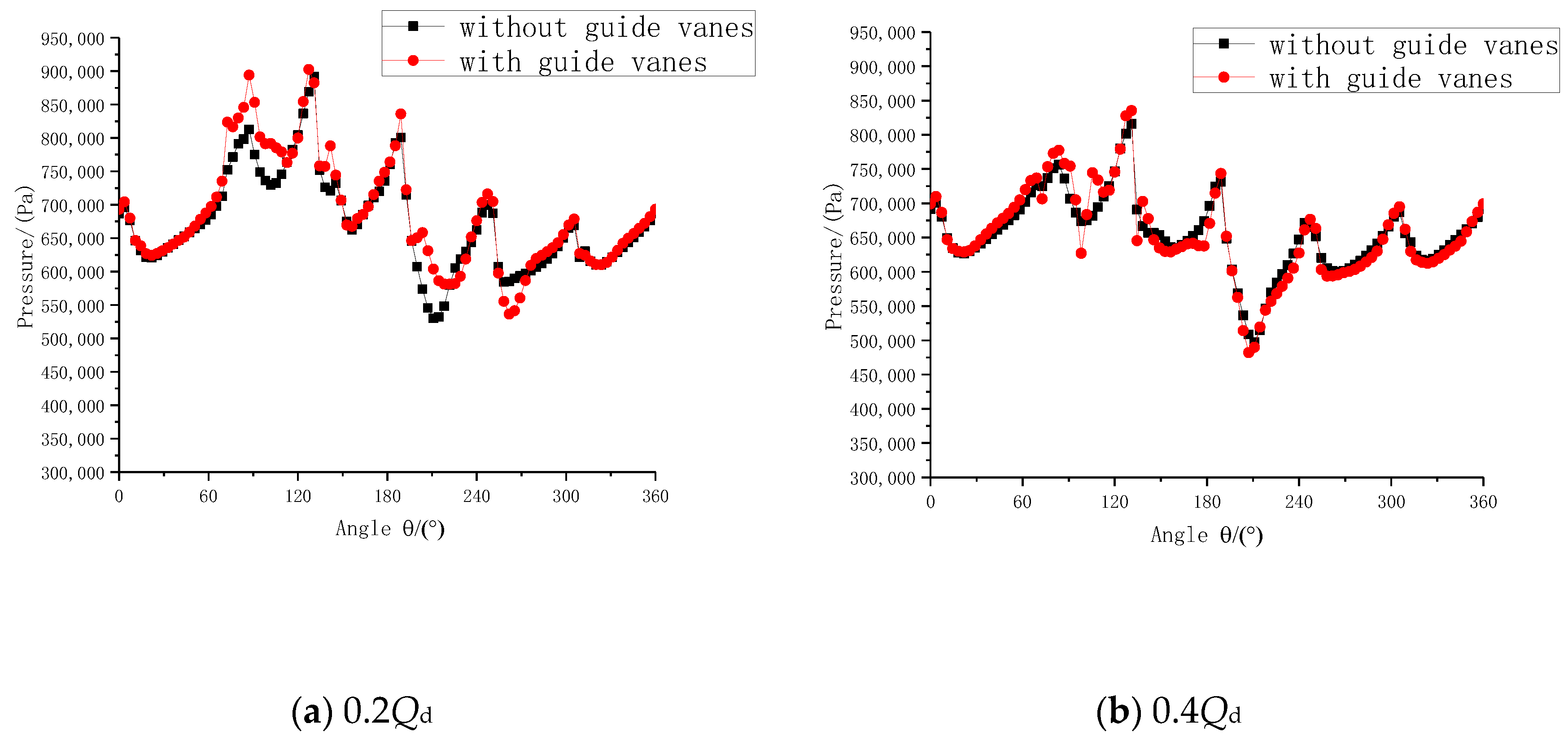
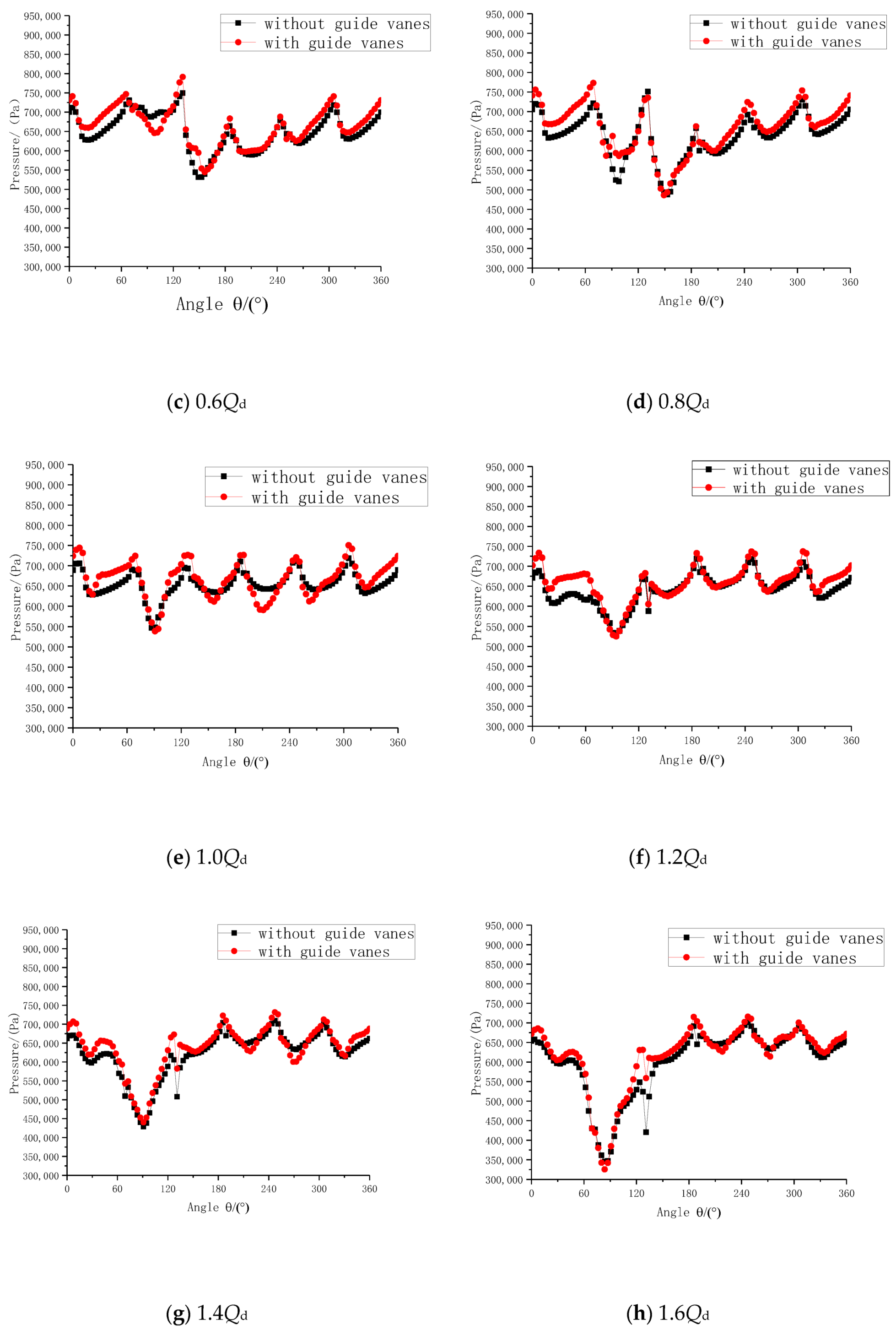
3.4.2. Stress Analysis

Figure 11 shows the static pressure distribution at the interface between the volute and the impeller. As can be seen from the figure, the static pressure at the interface fluctuates periodically along the circumference, and there are six peaks and troughs in total. At the operating points of 0.2Qd ~ 0.8Qd, the static pressure distribution at the interface of the pump with guide vanes and the pump without guide vanes is similar on the whole. However, the static pressure at the interface of the pump with guide vanes is slightly higher than that of the pump without guide vanes. At the working point of 1.0Qd ~ 1.6Qd, the static pressure at the interface produces a pressure sag near the septum tongue, with a minimum trough value and a large pressure gradient. This indicates that the flow of fluid in the septum tongue region is complex, and with the increase of flow rate, the trough value of static pressure at the septum tongue keeps decreasing, while at the working point of 1.6Qd, the trough value at the septum tongue reaches the minimum.

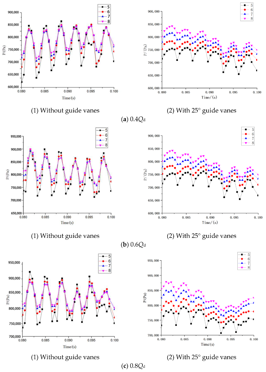
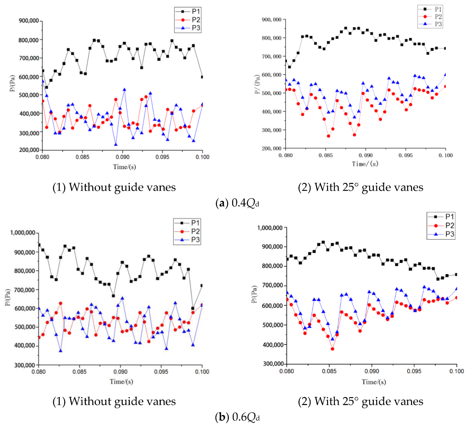
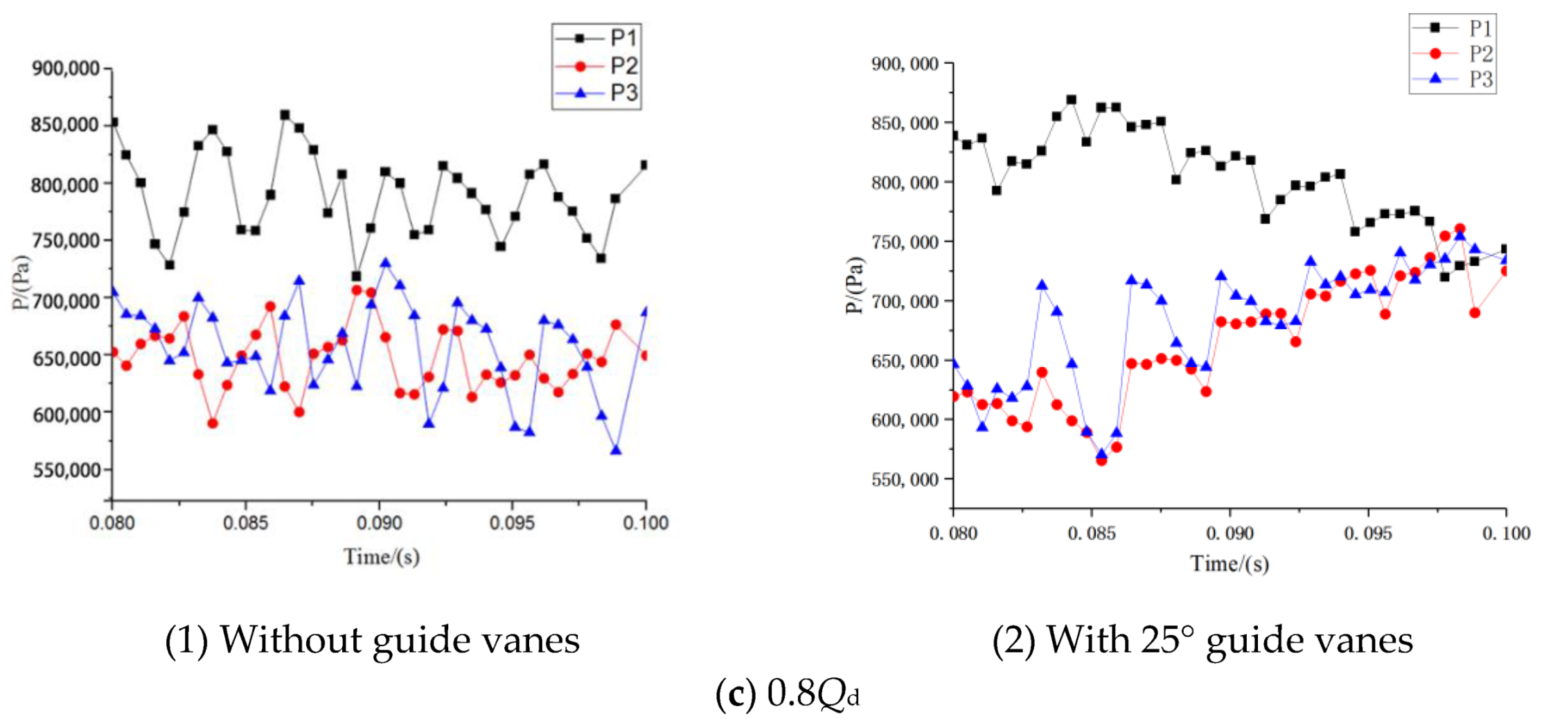
3.5. Pressure Pulsation Analysis

According to the analysis in the previous chapter, the inlet guide vane has an obvious influence on the flow of the centrifugal pump under the conditions of 0.4Qd, 0.6Qd, and 0.8Qd. On the basis of this chapter, in order to explore the influence of the positive offset angle guide vane on the internal flow under the small flow condition of the centrifugal pump, the pump with the guide vane with a positive offset angle of 25° and pump without guide vanes are selected. In contrast, the internal pressure pulsation distribution of the centrifugal pump under 0.4Qd, 0.6Qd, and 0.8Qd flow conditions was analyzed. Since the calculated model pump rated speed is 2900 rpm, the impeller needs to rotate one revolution, and the impeller rotates 1° for the time step. When the outlet pressure of the calculated model pump changes periodically with time, the unsteady calculation is considered to have converged. In order to ensure the accuracy of the calculated results, this paper selects the results of the fifth cycle for unsteady result analysis.

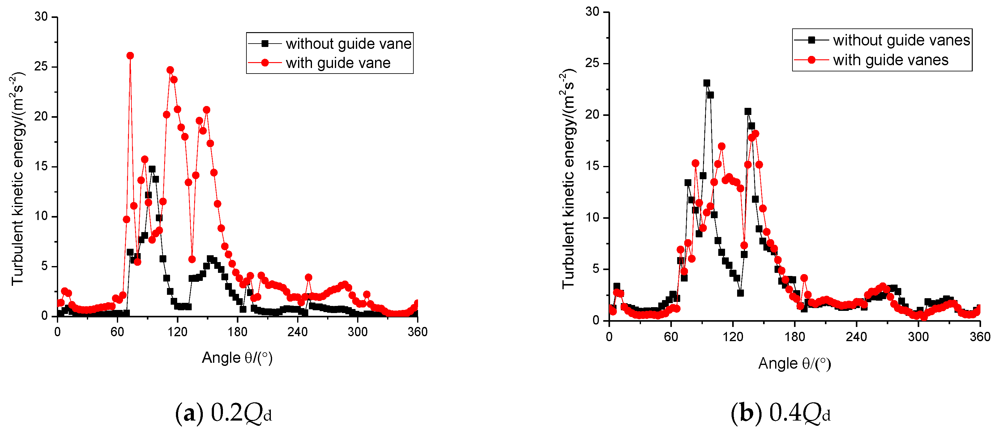
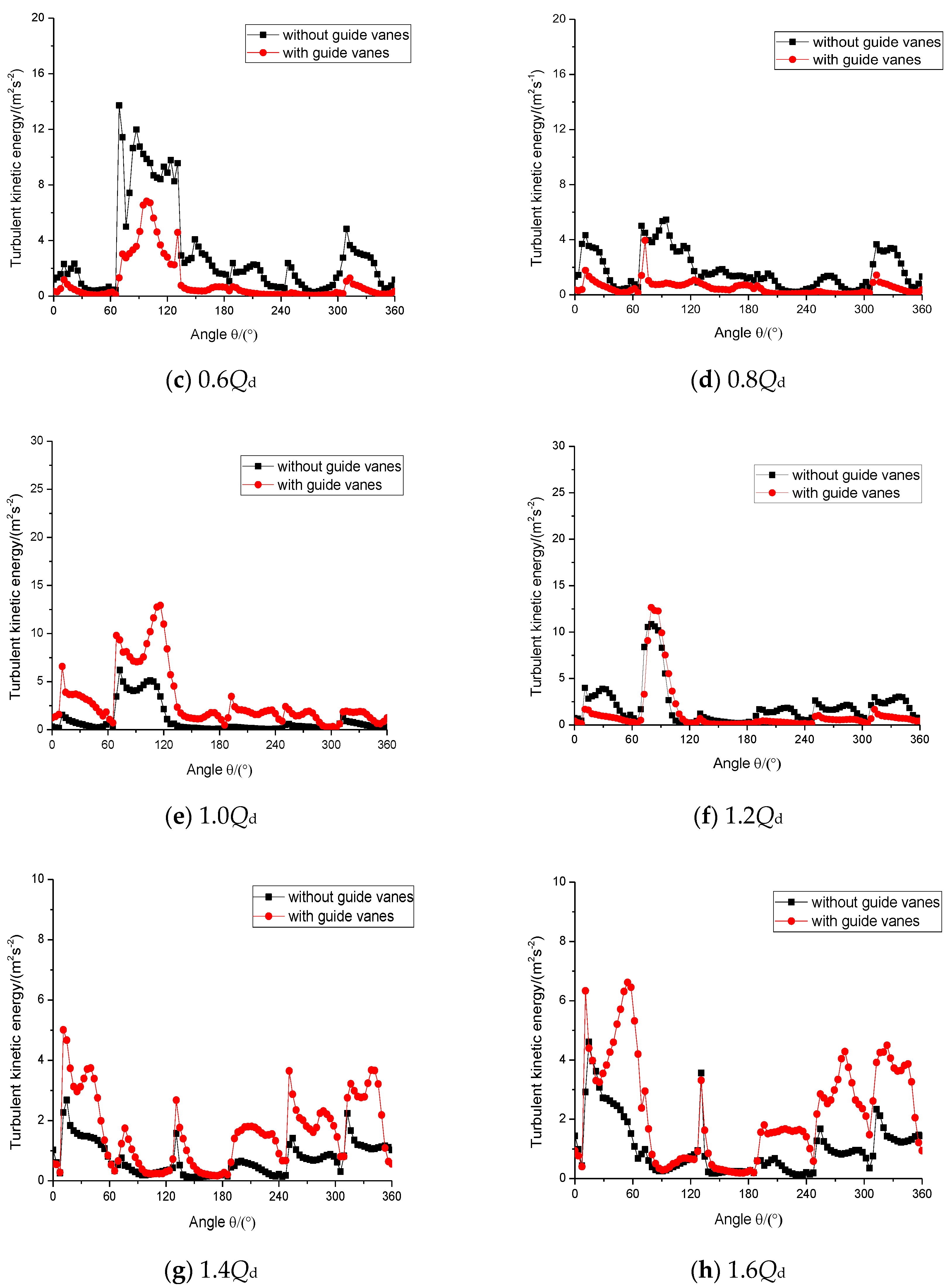
3.5.1. Stress Analysis

In order to study the pressure variation of the fluid in the impeller flowing from the impeller outlet into the volute channel, the pressure analysis of the representative flow sections VI and VIII in the volute flow channel was performed. The distribution of monitoring points is shown in Figure 7.
The static pressure distribution of the VI section of the volute is shown in Figure 12. It can be seen from the figure that the static pressure value of the VI section of the volute gradually increases along with the impeller outlet to the volute wall surface, and the point with the lowest static pressure value is close to one side of the impeller outlet. The maximum static pressure values at the 0.4Qd operating point of the pump without vanes and the pump with offset angle 25° vanes in the VI section of the volute are 954,351.62 Pa and 912,232.81 Pa, respectively, and the minimum static pressure values are 683,489.25 Pa and 689,718.75 Pa; at 0.6Qd operating point, the maximum static pressure values of the pump without guide vanes and the pump with offset angle 25° vanes in the VI section of the volute are 943,854.94 Pa and 974,721.19 Pa, and the minimum static pressure values are 710,325.62 Pa and 742,769.21 Pa; at 0.8Qd operating point, the maximum static pressure values of the pump without guide vanes and pump with offset angle 25° vanes in the VI section of the volute are 895,273.57 Pa and 917,815.94 Pa, and the minimum static pressure values are 720,154.36 Pa and 735,507.75 Pa; from the static pressure distribution of the VI section of the volute, it can be seen that the static pressure fluctuation of the pump with guide vanes at the offset angle of 25° on the VI section of the volute is small.
The static pressure distribution of the VIII section of the volute is shown in Figure 13. It can be seen from the figure that the static pressure value of the VIII section of the volute gradually increases along with the impeller outlet to the wall of the volute, and the point of the smallest static pressure is close to one side of the impeller outlet. The maximum static pressure values of the 0.4Qd operating point, pump without guide vanes and pump with offset angle 25° vanes in the VI section of the volute are 864,247.48 Pa and 842,394.25 Pa, respectively, and the minimum static pressure values are 625,418.55 Pa and 654,118.75 Pa; at 0.6Qd operating point, the maximum static pressure values of the pump without guide vanes and the pump with offset angle 25° vanes in the VI section of the volute are 902,581.32 Pa and 893,193.81 Pa, respectively, and the minimum static pressure values are 718,217.19 Pa and 674,511.65 Pa; at 0.8Qd operating point, the maximum static pressure values of the pump without guide vanes and the pump with offset angle 25° vanes in the VIII section of the volute are 925,087.16 Pa and 873,926.19 Pa, and the minimum static pressure values are 737,156.47 Pa and 710,034.56 Pa; it can be seen from the static pressure distribution of the VIII section of the volute that the amplitude of the static pressure fluctuation of the pump with offset angle 25° guide vanes in the VIII section of the volute is small, and the periodicity of the pressure pulsation is obvious.
The main reason for the dynamic and static interference between the impeller and the volute is the special asymmetrical structure of the centrifugal pump volute. The dynamic and static interference between the impeller and the volute will cause periodic pressure pulsation in the centrifugal pump. The geometry of the volute tongue is the most complicated, and it is also the most intense part of the dynamic and static interference. In order to study the pressure pulsation of the pump without guide vanes and the pump with offset angle 25° vanes near the volute tongue, three monitoring points are set along the direction of the impeller to obtain the pressure pulsation data near the volute tongue. The distribution of monitoring points is shown in Figure 7.
Figure 14 shows the comparison of pressure pulsation between the pump without guide vanes and the pump with offset angle guide vanes at the three monitoring points of the volute tongue. It can be seen from the figure that during the period of one rotation of the impeller, the three monitoring points show six pressure pulsating peaks. This is because the six blades are swept over the monitoring point, the peak of each monitoring point is located where the blade just sweeps over the monitoring point, and the pressure value reaches the maximum at this time. Under the three small flow conditions, the pressure pulsation peaks of each detection point appear in sequence. Due to the close proximity of the volute tongue, the dynamic and static interference between the impeller and the tongue is obvious, and the three monitoring pressure pulsation amplitudes of P1, P2, and P3 are relatively large. The pump with offset angle 25° vanes is smaller than that of the pump without guide vanes, and the pressure pulsation variation of the pump with 25° vanes at the P1 monitoring point is small; at the P2 and P3 monitoring points, the periodicity of the pressure pulsation of the pump with guide vanes at the offset angle of 25° is more obvious.

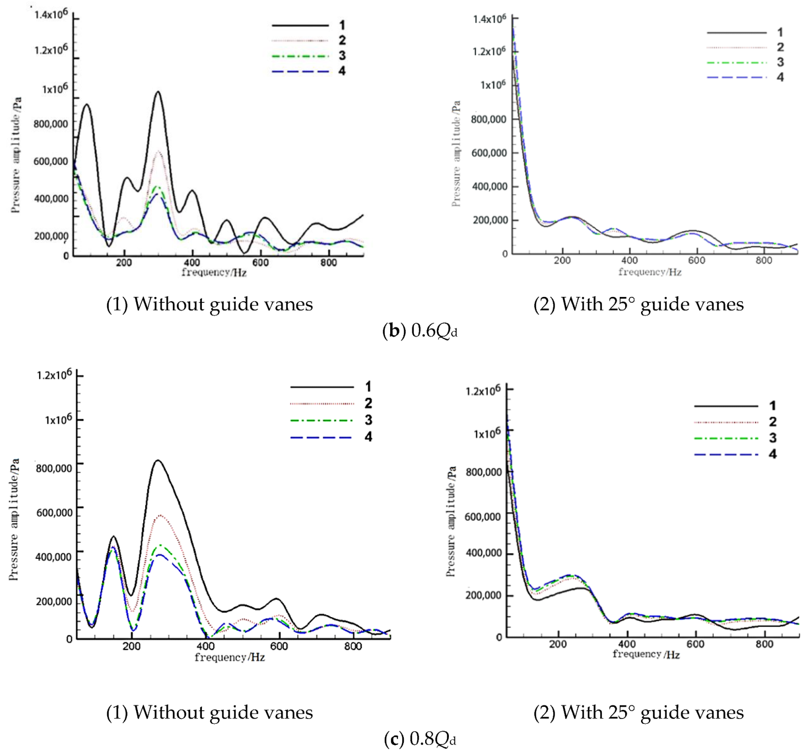
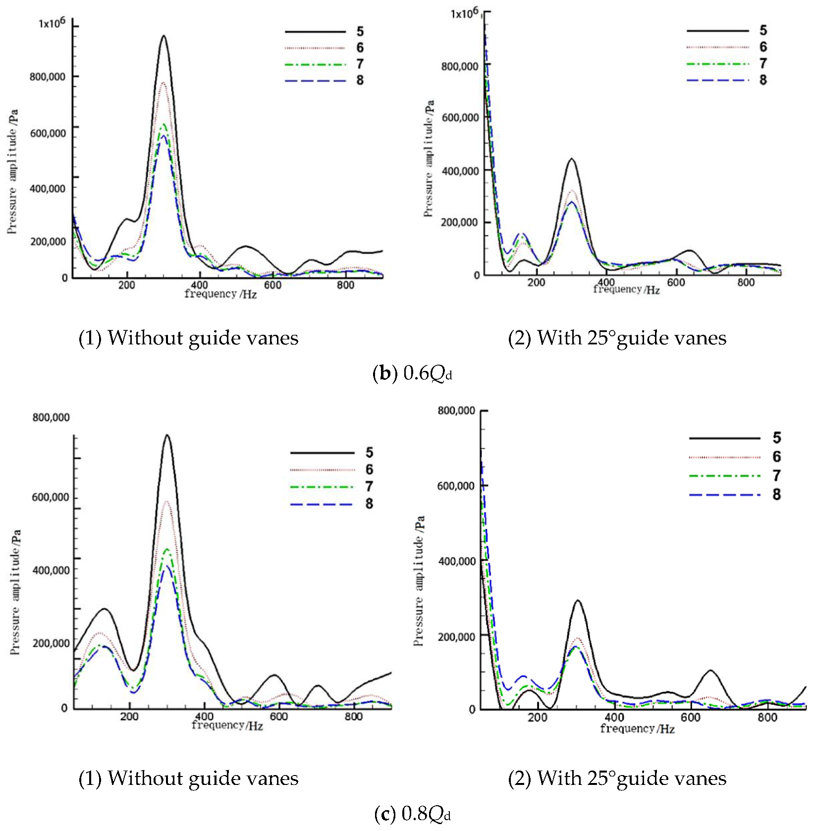
3.5.2. Frequency Domain Analysis of Pressure Pulsation

Figure 15 and Figure 16 are the frequency domain diagrams of the pressure pulsation of the volute section VI and the VIII section, respectively. It can be seen from the figure that the main frequency of the pressure pulsation at the three monitoring points with small flow rates is the passing frequency of the blade, and there is no obvious phase shift between the monitoring points on the volute section. As the flow rate continues to decrease, the amplitude of pressure pulsations at the same monitoring point gradually increases. Comparing the frequency domain diagrams of the pump without guide vanes and the pump with offset angle 25° vanes at the two volute cross-sections, it can be seen that the main frequency pressure pulsation amplitude of the pump without guide vanes at each monitoring point is higher than the amplitude of the pump with offset angle 25° vanes; the pumps without guide vanes have more complicated frequency characteristics at each monitoring point.

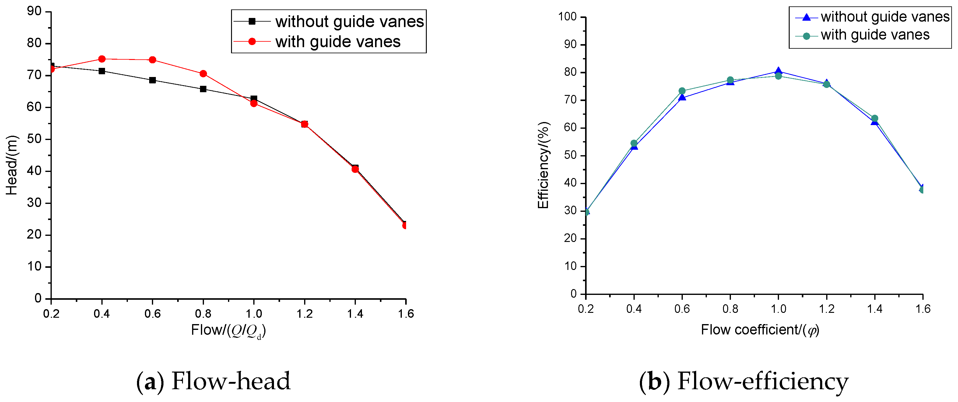
3.6. Analysis of External Characteristics of Centrifugal Pump

Figure 17 shows the comparison of the external characteristic curves of the numerical simulation of the centrifugal pump with and without guide vanes. It can be seen from the figure that the head of the centrifugal pump gradually decreases with the increase of the flow rate. The hydraulic efficiency of the centrifugal pump changes in a parabolic manner with increasing flow rate, first rising and then decreasing, which is consistent with the law of the external characteristic curve of the centrifugal pump. In the flow-head curve, the head of pump with guide vanes is improved at operating conditions of 0.4Qd, 0.6Qd, and 0.8Qd compared with that of the pump without guide vanes; at the design operating point of 1.0Qd and the large flow operating point, the head of pump with the guide vanes is slightly lower than that of the pump without guide vanes. In the flow-efficiency curve, the hydraulic efficiency of the pump with guide vanes at 0.4Qd, 0.6Qd, and 0.8Qd is higher than that of the pump without guide vanes; at the design working condition point 1.0Qd, the hydraulic efficiency of the pump without guide vanes is higher than that of the centrifugal pump with guide vanes, and at other operating conditions, the vane has no significant effect on the hydraulic efficiency of the centrifugal pump. This is because at the small flow operating point of 0.4Qd ~ 0.8Qd, the guide vane can improve the inlet flow pattern, reducing the hydraulic loss inside the centrifugal pump, so the head and hydraulic efficiency are improved; at the design working point of 1.0Qd, the guide vane has a certain disturbance effect on the internal flow of the centrifugal pump, resulting in a slight decrease in the head and efficiency; at the very small flow point of 0.2Qd and the large flow point 1.2Qd ~ 1.6Qd, the guide vane has little effect on the inlet flow pattern of the centrifugal pump, so it has little effect on the head and efficiency.

4. Concluding Remarks

In this paper, a numerical study is carried out to analyze the differences in the flow in the pump with and without inlet guide vanes, and some conclusions are drawn as follows.
At the low flow conditions point of 0.4Qd, 0.6Qd and 0.8Qd, the inlet guide vane has a certain inhibition effect on the vortex flow generated by the partial backflow phenomenon at the inlet of the centrifugal pump. The large vortex is divided into a local small eddy, which improves the stability of the flow in the pump, reduces the hydraulic loss and improves the hydraulic performance of the equipment, and significantly improves the velocity distribution and turbulent kinetic energy distribution in the passage of the blade rotating field. The inlet guide vane also has a positive effect on improving the velocity, pressure and turbulent kinetic energy distribution near the volute tongue in low flow conditions of 0.4Qd, 0.6Qd and 0.8Qd. Comparing the differences of the head and efficiency of the pump without guide vanes and the pump with vanes of offset angle 25° under different flow conditions, the head increased by 2.11%, 0.95%, and 0.73% at the three small flow conditions of 0.4Qd, 0.6Qd, and 0.8Qd, respectively; and efficiency increased by 2.51%, 1.67%, and 1.25%, respectively; the inlet guide vane weakens the inlet negative pressure area to some extent, which reduces the impact loss of the impeller inlet and increases the pump’s head and efficiency. The pump with vanes of offset angle 25° has a positive effect on the pressure distribution of the volute and the tongue, which reduces the complex frequency domain characteristics of the tongue.
At the design working conditions of 1.0Qd and the large flow rates conditions of 1.2Qd, 1.4Qd and 1.6Qd, the inlet guide vanes have a certain interference effect on the flow inside the impeller, resulting in a more uniform distribution of velocity and turbulent kinetic energy in the blade rotating flow, making the operation of the pump smoother.

Author Contributions

Conceptualization, P.L.; Formal analysis, Y.L. and H.C.; Experiment investigation, W.X. and Z.Z.; writing-original draft preparation, P.L.; writing-review and editing, Y.L. All authors have read and agree to the published version of the manuscript.

Funding

The present work is financially supported by the National Natural Science Foundation of China (Grant No. 51676173), the Key R & D Program of Zhejiang Province (Grant No. 2020C03081), the National Basic Research Program of China (Grant No. 613321), and 521 Talents Fostering Program Funding of Zhejiang Sci-Tech University of China. The supports are gratefully acknowledged.

Conflicts of Interest

The authors declare no conflict of interest.

References

  1. Aaronson, K.D.; Slaughter, M.S.; Miller, L.W.; McGee, E.C.; Cotts, W.G.; Acker, M.A.; Jessup, M.L.; Gregoric, I.D.; Loyalka, P.; Frazier, O.H.; et al. Use of an Intrapericardial, Continuous-Flow, Centrifugal Pump in Patients Awaiting Heart Transplantation. Circulation 2012, 125, 3191. [Google Scholar] [CrossRef] [PubMed] [Green Version]
  2. Steven, S.; Simon, S. Leviathan and the Air-Pump: Hobbes, Boyle, and the Experimental Life. Rev. Dhistoire Des. Sci. 1990, 43, 109–116. [Google Scholar]
  3. Chen, C.; Yuan, S.; Jin, S. Research Status and Prospects of Low Specific Speed Centrifugal Pumps. Fluid Mach. 1998, 27, 29–34. [Google Scholar]
  4. Dou, H.S. Mechanism of flow instability and transition to turbulence. Int. J. Non Linear Mech. 2006, 41, 512–517. [Google Scholar] [CrossRef]
  5. Zheng, L.; Dou, H.; Jiang, W.; Chen, X.; Zhu, Z.; Cui, B. Study on the influence of the number of blades on the stability of centrifugal pump based on energy gradient method. J. Zhejiang Sci. Tech. Univ. Nat. Sci. 2016, 35, 71–77. [Google Scholar]
  6. He, N. Analysis about the Influence of Operating Stability by Suction Specific Speed for Centrifugal Pumps in Petrochemical Plant. Petro Chem. Equip. Technol. 2010, 31, 27–29. [Google Scholar]
  7. MA, R.; MO, Y.; QIAN, K.; SUN, H.; SHI, H. Application of Internal Feedback Cascade Speed Control System with Chopper in Centrifugal Pump Working Condition Adjustment. Electric Eng. 2016, 5, 29–32. [Google Scholar]
  8. Chen, J.; Huang, Y. Discussion on Energy Saving Reconstruction of Centrifugal Pump. Urban Water Supply 2008, 68–69. [Google Scholar] [CrossRef]
  9. Fang, Q. Analysis of Condition Adjustment Method of Single Centrifugal Pump. Petro Chem. Equip. 2014, 17, 52–54. [Google Scholar]
  10. Xiao, J.; GU, C.G.; SHU, X.W.; GAO, C. Performance Analysis of a Centrifugal Compressor with Adjustable Inlet Guide Vanes. J. Power Eng. 2006, 6, 804–807. [Google Scholar]
  11. Zhou, R. The Influence of the Inlet Guide Vane on the Performance of Axial Flow Pump. Master’s Thesis, Yangzhou University, Yangzhou, China, 2012. [Google Scholar]
  12. Wang, J.; Yan, J.; Liu, H.; Shao, C.; Wang, Y. Influence on Unsteady Characteristics of Suction Chamber with Built-in Baffles in Low Specific Speed Centrifugal Pump. Fluid Mach. 2018, 46, 28–33. [Google Scholar]
  13. Coppinger, M.; Swain, E. Performance prediction of an industrial centrifugal compressor inlet guide vane system. Proc. Inst. Mech. Eng. Part A J. Power Energy 2000, 214, 153–164. [Google Scholar] [CrossRef]
  14. Li, X.; Chen, B.; Luo, X.; Zhu, Z. Effects of flow pattern on hydraulic performance and energy conversion characterisation in a centrifugal pump. Renew. Energy 2019. [Google Scholar] [CrossRef]
  15. Li, X.; Jiang, Z.; Zhu, Z.; Si, Q.; Li, Y. Entropy generation analysis for the cavitating head-drop characteristic of a centrifugal pump. Proc. Inst. Mech. Eng. Part C J. Mech. Eng. Sci. 2018, 232, 4637–4646. [Google Scholar] [CrossRef]
  16. Wang, C.; Chen, X.; Qiu, N.; Zhu, Y.; Shi, W. Numerical and experimental study on the pressure fluctuation, vibration, and noise of multistage pump with radial diffuser. J. Braz. Soc. Mech. Sci 2018, 40, 481. [Google Scholar] [CrossRef]
  17. Yang, H.; Zhang, W.; Zhu, Z. Unsteady mixed convection in a square enclosure with an inner cylinder rotating in a bi-directional and time-periodic mode. Int. J. Heat Mass Transf. 2019, 136, 563–580. [Google Scholar] [CrossRef]
  18. Wang, C.; He, X.; Shi, W.; Wang, X.; Wang, X.; Qiu, N. Numerical study on pressure fluctuation of a multistage centrifugal pump based on whole flow field. AIP Adv. 2019, 9, 35118. [Google Scholar] [CrossRef] [Green Version]
  19. Pei, J.; Zhang, F.; Appiah, D.; Hu, B.; Yuan, S.; Chen, K.; Asomani, S. Performance prediction based on effects of wrapping angle of a side channel pump. Energies 2019, 12, 139. [Google Scholar] [CrossRef] [Green Version]
  20. Li, B.; Li, X.; Jia, X.; Chen, F.; Fang, H. The Role of Blade Sinusoidal Tubercle Trailing Edge in a Centrifugal Pump with Low Specific Speed. Processes 2019, 7, 625. [Google Scholar] [CrossRef] [Green Version]
  21. Li, X.; Li, B.; Yu, B.; Ren, Y.; Chen, B. Calculation of cavitation evolution and associated turbulent kinetic energy transport around a NACA66 hydrofoil. J. Mech. Sci. Technol. 2019, 33, 1231–1241. [Google Scholar] [CrossRef]
  22. Li, X.; Yu, B.; Ji, Y.; Lu, J.; Yuan, S. Statistical characteristics of suction pressure signals for a centrifugal pump under cavitating conditions. J. Therm. Sci. 2017, 26, 47–53. [Google Scholar] [CrossRef]
  23. Wang, C.; He, X.; Cheng, L.; Luo, C.; Xu, J.; Chen, K.; Jiao, W. Numerical Simulation on Hydraulic Characteristics of Nozzle in Waterjet Propulsion System. Processes 2019, 7, 915. [Google Scholar] [CrossRef] [Green Version]
  24. Yang, H.; Yu, P.; Xu, J.; Ying, C.; Cao, W.; Wang, Y.; Zhu, Z.; Wei, Y. Experimental investigations on the performance and noise characteristics of a forward-curved fan with the stepped tongue. Meas. Control 2019, 52, 1480–1488. [Google Scholar] [CrossRef] [Green Version]
  25. He, X.; Jiao, W.; Wang, C.; Cao, W. Influence of surface roughness on the pump performance based on Computational Fluid Dynamics. IEEE Access 2019, 7, 105331–105341. [Google Scholar] [CrossRef]
  26. Hunt, J.C.; Wray, A.A.; Moin, P. Eddies, Streams, and Convergence Zones in Turbulent Flows; Proceedings of the Summer Program in Center for Turbulence Research; Stanford University: Stanford, CA, USA, 1988; pp. 193–208. [Google Scholar]
Figure 1. Three-dimensional model and mesh model of the centrifugal pump.
Processes 08 00122 g001
Figure 2. Schematic diagram of inlet guide vanes.
Processes 08 00122 g002
Figure 3. Grid diagram and the centrifugal pump with vanes.
Processes 08 00122 g003
Figure 4. The scheme of the test rig.
Processes 08 00122 g004
Figure 5. Comparison of experimental and simulation results for pump head and efficiency.
Processes 08 00122 g005
Figure 6. Numerical distribution of Q criteria for inlet and outlet sections with or without inlet guide vanes.
Processes 08 00122 g006
Figure 7. Volute cross section and monitoring point distribution.
Processes 08 00122 g007
Figure 8. Sectional velocity contour in the impeller.
Processes 08 00122 g008aProcesses 08 00122 g008b
Figure 9. Turbulent kinetic energy distribution in the impeller.
Processes 08 00122 g009aProcesses 08 00122 g009b
Figure 10. Velocity distribution in the volute cross-section.
Processes 08 00122 g010aProcesses 08 00122 g010b
Figure 11. Pressure analysis of interface between volute and impeller.
Processes 08 00122 g011aProcesses 08 00122 g011b
Figure 12. Static pressure distribution of section VI for different flow rates: (a) 0.4Qd, (b) 0.6Qd, (c) 0.8Qd.
Processes 08 00122 g012aProcesses 08 00122 g012b
Figure 13. Static pressure distribution of section VIII for different flow rates: (a) 0.4Qd, (b) 0.6Qd, (c) 0.8Qd.
Processes 08 00122 g013
Figure 14. Monitoring point pressure pulsation near the tongue for different flow rates: (a) 0.4Qd, (b) 0.6Qd, (c) 0.8Qd.
Processes 08 00122 g014aProcesses 08 00122 g014b
Figure 15. Frequency domain diagram of pressure pulsation in Section VI for different flow rates: (a) 0.4Qd, (b) 0.6Qd, (c) 0.8Qd.
Processes 08 00122 g015aProcesses 08 00122 g015b
Figure 16. Frequency domain diagram of pressure pulsation in section VIII for different flow rates: (a) 0.4Qd, (b) 0.6Qd, (c) 0.8Qd.
Processes 08 00122 g016aProcesses 08 00122 g016b
Figure 17. External characteristic curve of centrifugal pump.
Processes 08 00122 g017
Table 1. Main design parameters of centrifugal pump.
ParameterParameter Value
Design flow rate Qd (kg/s)16.637
Head H (m)60
Rotating speed n (rpm)2900
Effectiveness η (%)80
Specific speed ns19.9
Inlet diameter D1 (mm)94
Diameter of impeller D2 (mm)220
Impeller outlet width b1 (mm)15
Volute outlet diameter D3 (mm)70
Table 2. Grid independence check for the simulation.
GridGrid1Grid2Grid3Grid4
Number of grids1,220,8441,831,2662746,8994,120,348
Predicted head/m61.4361.6361.2861.03

