Article

The Direct Speed Control of Pmsm Based on Terminal Sliding Mode and Finite Time Observer

School of Electrical Engineering, Southeast University, Nanjing 210096, China
*
Authors to whom correspondence should be addressed.
Processes 2019, 7(9), 624; https://doi.org/10.3390/pr7090624
Submission received: 22 August 2019 / Revised: 10 September 2019 / Accepted: 10 September 2019 / Published: 16 September 2019

Abstract

:
A non-singular terminal sliding mode control based on finite time observer is designed to achieve speed direct control for the permanent magnet synchronous motor (PMSM) drive system. Speed and current are regulated in one loop under the non-cascade structure, taking place of the cascade structure control method in the vector control of PMSM. Based on the second-order speed function of the PMSM, the disturbance and parameters uncertainties are estimated by the designed finite time observer (FTO), and compensate to the drive system. The estimated value of the finite time observer will converge to the actual disturbance value in a finite time. A second-order non-singular terminal sliding mode controller is proposed to realize the speed and current single-loop, which can track the reference speed and reference current in a finite time. Rigorous stability analysis is established. Comparative results verified that the proposed method has faster speed tracking performance and disturbance rejection property.

1. Introduction

By reason of the high-power density, torque-to-inertia ratio and high efficiency, the permanent magnet synchronous motor (PMSM) are widely used in industrial areas, such as, aerospace, servo control, numerical control machine and robot [1,2,3,4,5]. In these applications, the dynamic response performance and disturbance rejection property of PMSM are very important.
In recent years, with the progress of technology, the control periods between the speed loop and current loop of PMSM gradually decreased, or even vanished [6]; making it possible to realize the speed-current single-loop of PMSM drive system under the non-cascade structure. Generally speaking, in the traditional cascade control method for PMSM, the control period of the speed loop is 5–10 times that of the current loop, reducing the real-time control performance of the speed [7,8,9]. When the same control algorithm is adopted, different from the cascade control structure, the number of adjustable parameters is reduced and the speed can be directly controlled. These are the virtues of the non-cascade control structure [10,11]. Despite its advantages, there is little research on non-cascade control structures for the PMSM system in recent years. A non-cascade structure control based on model predictive control is proposed in [12], in which the dynamic performance of the system is improved and the computational complexity is reduced, compared with the traditional cascade predictive control method. In [13], under the non-cascade structure, the speed and current are adjusted in one proportion integration differentiation (PID) controller. Rigorous theoretical derivation and experimental analysis verified that the proposed method has better dynamic performance and disturbance rejection ability. Considering the influence of various disturbances on the PMSM system, a new non-cascade structure controller is established in [14], which can directly control the speed of PMSM. PMSM speed and current are adjusted in one loop based on terminal sliding mode and nonlinear disturbance observer under non-cascade structure control in [15]. However, when without the nonlinear disturbance observer, the proposed method has a poor ability to deal with the load sudden change. A direct speed control method based on radial basis function (RBF) is designed in [16], which avoided the control of current, simplified the control structure and improved the control performance. A model predictive direct speed control method based on voltage vector control is proposed in [17]. In this method, the voltage vector does not need to be measured, the computational burden of the system is reduced, and the output current is constrained within a certain range. A model predictive direct speed controller is proposed in [18], which overcomes the shortcoming of cascade linear controller in high-speed control, and the results show that the proposed method has better stability performance. Based on the state-dependent Riccati equation (SDRE) and Convex constrained optimization, a direct speed controller was proposed in [19], which can make the PMSM control system achieve high dynamic and accurate stability performance, and the input voltage and stator current can be constrained.
Due to the nonlinear and strong coupling characteristics of the PMSM drive system, ideal control results can hardly be achieved in traditional PI controller [20,21]. Many nonlinear control methods have been applied in PMSM drive systems, such as sliding mode control, model predictive control, auto-disturbance rejection control, finite time control, etc., [22,23,24,25,26]. Among these methods, it can converge in finite time and has a better disturbance rejection performance. The terminal sliding mode is widely used in control systems. In [27], a new terminal sliding mode controller is designed to adjust the speed of the PMSM servo system, which can make the system reach the reference speed in a finite time, ensuring a fast convergence performance and a better tracking accuracy of the system. In [28], a non-singular terminal sliding mode control based on state observer is investigated to realize the pressure control. In the proposed method, the pressure tracking error can converge to the equilibrium point in finite time and the chattering of the sliding mode is weakened. In [29] according to euler discrete technology, a new discrete time fast terminal sliding mode method is proposed and applied to the control of permanent magnet synchronous linear motor (PMLSM), and the reference position of PMLSM can be quickly tracked. In [30], a fractional-order terminal sliding mode controller based on fractional-order disturbance observer is proposed, under which the speed can converge to the reference speed in a finite time. In [31], a higher speed tracking accuracy can be achieved by a continuous fast terminal sliding mode control, and the robustness of the PMSM system can be improved when the disturbance is feedforward to the system by the extended state observer. In [32], a nonsingular terminal sliding mode based on improved extended state observer is investigated to realize the direct voltage control for the stand-alone doubly-fed induction generator (DFIG) system, which can achieve a balanced stator voltage.
Load change, parameters uncertainty and unmodeled dynamics are considered to be important factors affected the control performance. At present, in order to improve the robustness, the disturbance will be estimated by state observer and feed forward to the system before it affects the system. In [33], to improve the robustness in surface permanent magnet synchronous motor, the lumped disturbance consisted of the external disturbance and mismatched parameters can be estimated by a Luneburg observer, and compensate to the PMSM system. In [34] the parameters uncertainties and disturbances in DC-DC converters are considered as lumped disturbance, estimated by a reduced order generalized proportional integral observer and fed forward to the system, which improves the dynamic performance of the system. In [35], the lumped disturbance in air-breathing hypersonic vehicles is calculated by a disturbance observer, and the accuracy of speed and position control is improved when the disturbance feedforward to the system. In [36], a high-gain generalized proportional integral observer is designed, to estimate the load change and parameters uncertainties in PMSM. In [37], the disturbance is estimated and compensated by a nonlinear disturbance observer to improve the disturbance rejection property of the system. Then, a nonlinear controller is used to control the system, and the semi-global stability of the designed nonlinear controller and nonlinear disturbance observer is proved. In [38], a robust nonlinear observer is proposed for the Lipschitz nonlinear system. On the one hand, the new observer does not need to be added to small Lipschitz constants; on the other hand, the state estimation error of the system can quickly approach zero in the face of large additional disturbances. Disturbance also exists in the PMSM drive system under the non-cascade structure. In order to improve the anti-disturbance ability, it is necessary to estimate and compensate the disturbance to the system.

2. Preliminaries

2.1. The Mathematical Model of Pmsm

The ideal model of a surface mounted PMSM in the d-q frame can be expressed as follows.
{ d i d d t = R i d + n p ω L i q L + 1 L u d d i q d t = R i q n p ω L i d n p ω ψ f L + 1 L u q d ω d t = B ω J + n p ψ f J i q T L J
where, i d , i q are the d-axis and q-axis stator currents, respectively; u d , u q are the d-axis and q-axis stator voltages, respectively; L is the inductor; R is stator resistance; n p is the number of pole pairs; ω is angular velocity; ψ f is rotor flux linkage; T L is load torque; B is viscous frictional coefficient; J is rotor inertia.

2.2. The Mathematic Model of Speed-Current Single-Loop

Let x 1 = ω r e f ω , and its derivative can be expressed as
x ˙ 1 = x 2 = ω ˙ r e f ω ˙ = ω ˙ r e f + a 1 ω a 2 i q + a 3 T L .
where, a 1 = B J , a 2 = n p ψ f J , a 3 = 1 J .
When the parameters uncertainties are considered, the following expression can be obtained.
x ˙ 1 = x 2 + d 1 = ω ˙ r e f + a 1 ω a 2 i q + a 3 T L + d 1
where, d 1 = Δ a 1 ω Δ a 2 i q + Δ a 3 T L is considered as mismatched uncertainties. And a 1 , a 2 , a 3 are nominal parameter values, a t 1 , a t 2 , a t 3 are the actual parameter values. Δ a 1 = a t 1 a 1 , Δ a 2 = a t 2 a 2 , Δ a 3 = a t 3 a 3 .
The second order differential equation of speed error can be expressed as follows
x ˙ 2 = ω ¨ r e f ω ¨ = ω ¨ r e f + a 1 ω ˙ a 2 i ˙ q + a 3 T ˙ L .
Considering system (1), the (4) can be rewritten as
x ˙ 2 = ω ¨ r e f + a 1 ω ˙ + a 2 b 1 i q + a 2 b 2 ω i d + a 2 b 3 ω a 2 b 4 u q + a 3 T ˙ L .
where b 1 = R L , b 2 = n p , b 3 = n p ψ f L and b 4 = 1 L .
Taking the parameters uncertainties and disturbance into consideration, system (5) can be expressed as follows
x ˙ 2 = a 1 x 2 a 2 b 3 x 1 a 2 b 4 u q + d 2 .
where, d 2 = ω ¨ r e f + a 1 ω ˙ r e f + a 2 b 3 ω r e f + a 2 b 1 i q + a 2 b 2 ω i d + a 3 T ˙ L Δ a 1 x 2 Δ a 2 Δ b 3 x 1 + Δ a 1 ω ˙ r e f + Δ a 2 Δ b 3 ω r e f + Δ a 2 Δ b 1 i q + Δ a 2 Δ b 2 ω i d Δ a 2 Δ b 4 u q + Δ a 3 T ˙ L .
b 1 , b 2 , b 3 , b 4 are the nominal parameter values, b t 1 , b t 2 , b t 3 , b t 4 are the actual parameter values, Δ b 1 = b t 1 b 1 , Δ b 2 = b t 2 b 2 , Δ b 3 = b t 3 b 3 , Δ b 4 = b t 4 b 4 .
The second-order speed regulation system can be expressed as follows
{ x ˙ 1 = x 2 + d 1 x ˙ 2 = a 1 x 2 a 2 b 3 x 1 a 2 b 4 u q + d 2

3. Control Design

Based on the method designed in this paper, the PMSM control structure block diagram is shown in Figure 1.

3.1. Finite Time Observer

The disturbance is estimated and feedforward to the system based on the finite time observation method. The stability of the finite time control system is defined as follows.
Lemma 1.
[39] the following system is considered
x ˙ = f ( x ) , x U R n , f ( 0 ) = 0
where, f : U R n is a continuous function of x in domain of definition. For the equilibrium solution of the system, x = 0 is defined as finite time stability, which requires the system to be both stable and convergent in finite time. Finite time convergence means there are x 0 U 0 R n and a continuous function T ( x ) : U 0 \ { 0 } ( 0 , + ) , making the solution x ( t , x 0 ) of the system (3) satisfied the following conditions: when t [ 0 , T ( x 0 ) ) , x ( t , x 0 ) U 0 \ { 0 } and lim x T ( x 0 ) x ( t , x 0 ) = 0 are true; When t > T ( x 0 ) , x ( t , x 0 ) = 0 is always true. If U = U 0 = R n existed, the system is considered globally finite time stable.
Notation 1.
For writing convenience, denote s i g β ( x ) = sgn ( x ) | x | β , where x , β , and sgn ( ) is the sign function.
Lemma 2.
[40] Consider the following system
x ˙ = f ( x ) + f ^ ( x ) , f ( 0 ) = 0 , x n
where, f ( x ) is a continuous homogeneous vector field, and f ( x ) has negative homogeneous degree k with respect to expansion vector ( r 1 , r 2 , , r n ) . f ^ ( x ) is the estimated disturbance of the system, which satisfies f ^ ( 0 ) = 0 . x n refers that x is belonged to the n-dimensional vector. Suppose that the asymptotically stable equilibrium point of system x ˙ = f ( x ) is x = 0 and satisfies the following conditions, x 0
lim ε 0 f ^ i ( ε r 1 x 1 , , ε r n x n ) ε k + r i = 0 , i = 1 , 2 , , n
Then x = 0 is a locally finite time equilibrium point of system (9).
Lemma 3.
[41,42,43] Consider the nonlinear system
{ x ˙ i = x i + 1 , i = 1 , , n 1 x ˙ n = u y = x 1
where, x = ( x 1 , x 2 , , x n ) T R n are the state variables of the system; u R and y R are the input and output of the system, respectively.
For system (11), the estimated state values ( x ^ 1 , x ^ 2 , , x ^ n ) can converge to the real states ( x 1 , x 2 , , x n ) of system (11) in a finite time by the following global finite time observer.
{ x ^ ˙ i = x ^ i + 1 + λ i s i g β i ( x 1 x ^ 1 ) , i = 1 , 2 , , n 1 x ^ ˙ n = u + λ n s i g β n ( x 1 x ^ 1 )
where, β i > 0 , i = 1 , 2 , , n , it’s a Hurwitz polynomial s n + β 1 s n 1 + + β n 1 s + β n .
β i = i β ( i 1 ) , i = 1 , , n , β ( 1 1 n , 1 ]
Lemma 4.
[44,45] A second-order system can be expressed as follows
{ x ˙ 1 = x 2 λ s i g 1 2 ( x 1 ) x ˙ 2 = ν s i g n ( x 1 ) + F ( t )
If there is a positive real number f + , | F ( t ) | < f + is true, and ν , λ satisfies the following description.
ν > f + , λ > 2 ν f + ( ν + f + ) ( 1 + μ ) ( 1 μ )
where, μ is a constant, 0 < μ < 1 . Then the state ( x 1 , x 2 ) of the system (14) will be converged to the equilibrium point 0 in a finite time, and the system (14) is globally stable in finite time.
Assumption 1.
The disturbance d 1 , d 2 in system (7) are second-order and first-order differentiable, respectively.
Let x ¯ 1 = x 1 , x ¯ 2 = x 2 + d 1 , d = d ˙ 1 + d 2 + a 1 d 1 , the following system can be derived from system (7)
{ x ¯ ˙ 1 = x ¯ 2 x ¯ ˙ 2 = a 1 x ¯ 2 a 2 b 3 x ¯ 1 a 2 b 4 u q + d y = x ¯ 1
Finite time state observers are designed for the state variables of system (7) and system (14) according to Lemma 3.
{ x ¯ ^ ˙ 1 = x 2 + d ^ 1 λ 1 s i g β 1 ( x ¯ ^ 1 x 1 ) d ^ ˙ 1 = λ 2 s i g n ( x ¯ ^ 1 x 1 )
{ x ¯ ^ ˙ 2 = a 1 x ¯ ^ 2 2 a 2 b 3 x ¯ ^ 1 1 a 2 b 4 u q + d ^ 2 + a 1 d ^ 1 λ ¯ 1 s i g β 2 ( x ¯ ^ 2 x ¯ 2 ) d ^ ˙ 2 = λ ¯ 2 s i g n ( x ¯ ^ 2 x ¯ 2 )
where, λ 1 , λ 2 , λ ¯ 1 , λ ¯ 2 are the observation gain of the finite time observer, β 1 , β 2 are the fractional power of the finite time observer, x ¯ ^ 1 , x ¯ ^ 2 , d ^ 1 , d ^ 2 are the estimated values of x ¯ 1 , x ¯ 2 , d 1 , d 2 . The following function can be acquired d ^ = a 1 d ^ 1 + d ^ 2 , where, d ^ is the estimated value of d.
Proof: The estimated errors are defined as x ˜ 1 = x ¯ ^ 1 x ¯ 1 , d ˜ 1 = d ^ 1 d 1 . The error equation obtained by system (7) and system (17) can be expressed as
{ x ˜ ˙ 1 = d ˜ 1 λ 1 s i g β 1 ( x ˜ 1 ) d ˜ ˙ 1 = λ 2 s i g β 2 ( x ˜ 1 ) d ˙ 1
From Assumption 1, L d ˙ 1 L can be obtained. When the gain meets (15), the error system can be reached stability within a finite time. Namely, d ^ 1 can converge to the true value d 1 in finite time. After this moment, d ^ 1 d 1 , x ¯ ^ 1 x ¯ 1 are always true. Then x ¯ 2 x 2 + d ^ 1 is true. The proof of the finite time stability of the error system for the system (17) is the same as above.
In conclusion, the observation state ( x ¯ ^ 1 , x ¯ ^ 2 , d ^ 1 , d ^ 2 ) estimated by the finite time observer will converge to the actual values ( x ¯ 1 , x ¯ 2 , d 1 , d 2 ) of system (7) and system (18) within a finite time.

3.2. Non-Singular Terminal Sliding Mode Control

Consider the following second-order system
{ e ˙ 1 = e 2 e ˙ 2 = f ( e ) + u + d ( t )
where, e 1 , e 2 are the state variables, d(t) is the disturbance, | d ( t ) | D .
The non-singular terminal sliding mode surface is selected as follows
s = e 1 + 1 η e 2 p / q
where, η > 0 , and p > q > 0 are odd.
In order to make the system state converge to the actual value in finite time, the control law can be designed as
u = ( D + ε ) s i g n ( s ) f ( e ) η q p e 2 2 p / q
where, ε is the robustness coefficient, ε > 0 , 1 < p / q < 2 .
In order to prove the stability of the designed system, the Lyapunov function is selected as
V = 1 2 s 2
The derivative of V is as following
V ˙ = s s ˙ = s ( e ˙ 1 + 1 η p q e 2 p / q 1 e ˙ 2 ) = s [ e 2 + 1 η p q e 2 p / q 1 ( f ( e ) + u + d ( t ) ) ] = s [ e 2 + 1 η p q e 2 p / q 1 ( f ( e ) + u + d ( t ) ) ] = s [ e 2 + 1 η p q e 2 p / q 1 ( ( D + ε ) s i g n ( s ) η q p e 2 2 p / q + d ( t ) ) ] = s [ 1 η p q e 2 p / q 1 ( ( D + ε ) s i g n ( s ) + d ( t ) ) ] 1 η p q e 2 p / q 1 ( ε ) | s |
where p , q are positive odd integers and 1 < p / q < 2 , thus e 2 p / q 1 > 0 . Then V ˙ < 0 is always true.
According to the above analysis, the control law (22) designed for system (20) can ensure the system convergence.
Assume that the system state reaches the sliding mode surface at tr, that is to say s ( t r ) = 0 , then
{ e 1 + 1 η e 2 p / q = 0 e ˙ 1 = η e 1 q / p
The time it takes for the system to stabilize to the equilibrium point can be expressed as
t s = p η ( p q ) | e 1 ( t r ) | 1 q / p
As can be seen from the time function (26), the larger η is, the smaller t s is to the stable state; However, if η is too large, the effect of switching item will be strengthened due to the change of s symbol, and the control output will be weakened.
For system (16) (17) (18), the non-singular terminal sliding mode surface function is selected as
s = x ¯ 1 + 1 η x ¯ ^ 2 p / q
The control law is designed as
u q = 1 a 2 b 4 [ a 1 x ¯ ^ 2 a 2 b 3 x ¯ 1 + d ^ + η q p x ¯ ^ 2 2 p / q + ( D + ε ) s i g n ( s ) ]
Choose the Lyapunov function as
V = 1 2 s 2
Derivation of (29)
V ˙ = s s ˙ = s ( x ¯ ˙ 1 + 1 η p q x ¯ ^ 2 p / q 1 x ¯ ^ ˙ 2 ) = s [ x ¯ ^ 2 + 1 η p q x ¯ ^ 2 p / q 1 ( a 1 x ¯ ^ 2 a 2 b 3 x ¯ 1 a 2 b 4 u q + d ) ]
Consider the control law (28)
V ˙ = s [ 1 η p q x ¯ ^ 2 p / q 1 ( ( D + ε ) s i g n ( s ) d ^ + d ) ] = s [ 1 η p q x ¯ ^ 2 p / q 1 ( ε s i g n ( s ) + d d ^ D s i g n ( s ) ) ] 1 η p q x ¯ ^ 2 p / q 1 ( ε ) | s | 0
In (31), p , q are positive odd integers and 1 < p / q < 2 , thus x ¯ ^ 2 p / q 1 > 0 is true, and η > 0 , so 1 η p q | s | > 0 is true, because ε > 0 , then 1 η p q x ¯ ^ 2 p / q 1 ( ε ) | s | < 0 can be proved.
It can be known from (31) that the second-order PMSM system can reach a stable state in a finite time based on the composite strategy of finite time observer and non-singular fast terminal sliding mode.

4. Simulation and Analysis

In order to verify the effectiveness of the proposed method, comparative simulations are built on the traditional cascade PID, cascade sliding mode, and the proposed method this paper. The simulations are based on Asus notebook FX503VD, Intel(R)Core i7 7700HQ, [email protected], RAM 7.88GB (Hynix DDR4 2400MHz), SanDiskSD8SN8U128G1002(128GB/solid state disk), Nvidia GeForce GTX 1050 (4GB/Asus), 64-bit operating system, matlab 2017b (ASUSTek Computer Inc., Taiwan, China). In order to ensure the fairness of the comparison, the bus voltage is set to 36 V. The reference speed of PMSM is set at 1000 r/min. The PMSM parameters used for simulation are shown in Table 1. The parameters of the traditional cascade PID, the traditional cascade sliding mode control and NTSMC-FTO proposed in this paper are shown in Table 2, Table 3, and Table 4, respectively. In cascade SMC controller, SMC and PID are used for speed loop and current loop, respectively. s = c x 1 + x 2 is taken as the sliding mode surface of SMC, and i q = 2 J 3 n p ψ f 0 t [ c ( x 2 ) + M u × s i g n ( s ) + κ s ] d t as the expression of output.
There are two groups of comparative simulations, one is the response curve at the phase of startup, and the other is the response curve when the load torque suddenly changes at a constant speed stage. It can be found from the comparison results that the NTSMC-FTO proposed in this paper, which regulate the speed and current of PMSM in one loop, has a better dynamic performance and disturbance rejection property than the traditional PID and SMC.
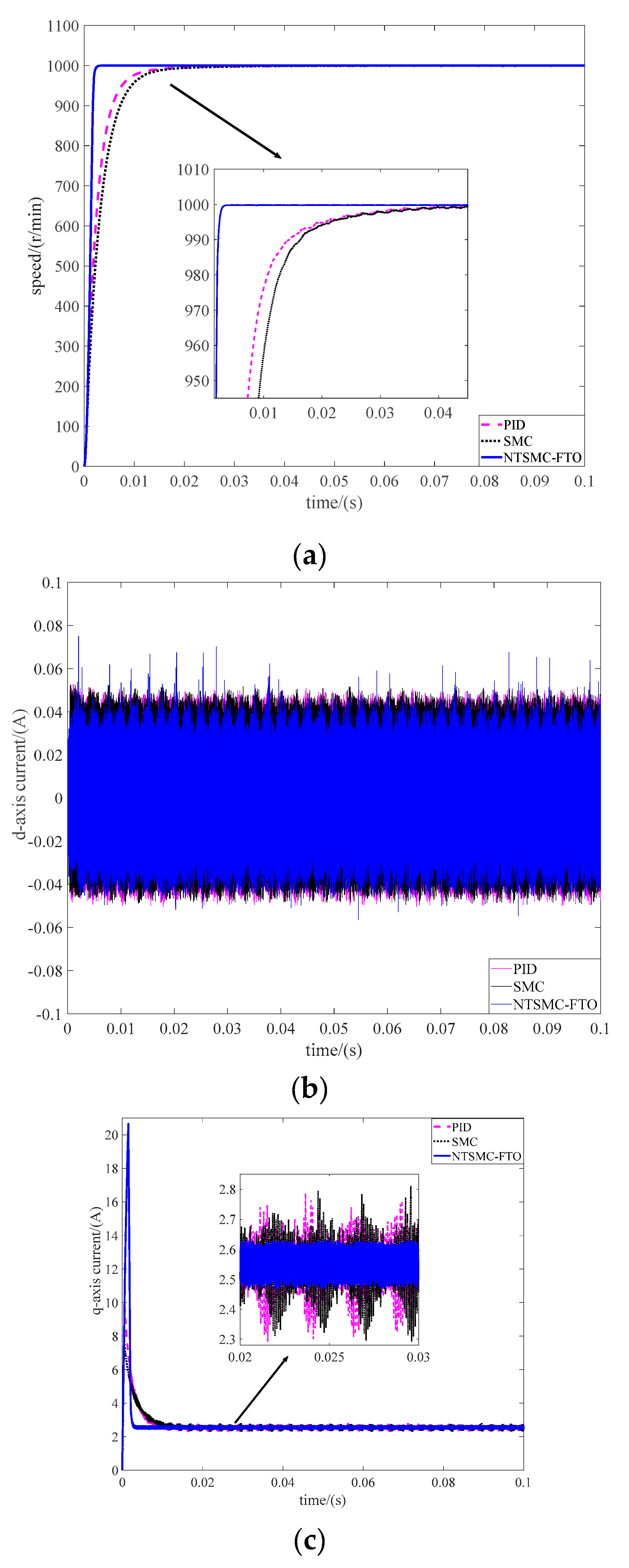
Case I: Phase of start. The reference speed of PMSM is set at 1000 r/min, and the motor starts without load torque. Figure 2a–c are ω , i q , i d response curves of startup, respectively. The solid (blue) line is NTSMC-FTO controller, the dotted (pink) line is PID controller, and the dotted (black) line is SMC controller. It can be summarized that when the motor starts without speed overshoot, When the motor starts without speed overshoot, it takes 0.0028 s for NTSMC-FTO to reach the steady state, compared with the cascade SMC and PID 0.045 s is needed. The cost to reach steady state is reduced by 0.0422 s. The d-axis and q-axis currents chattering of NTSMC-FTO are smaller than the cascade SMC and PID controller. The comparative simulation results of startup can be seen in Table 5.
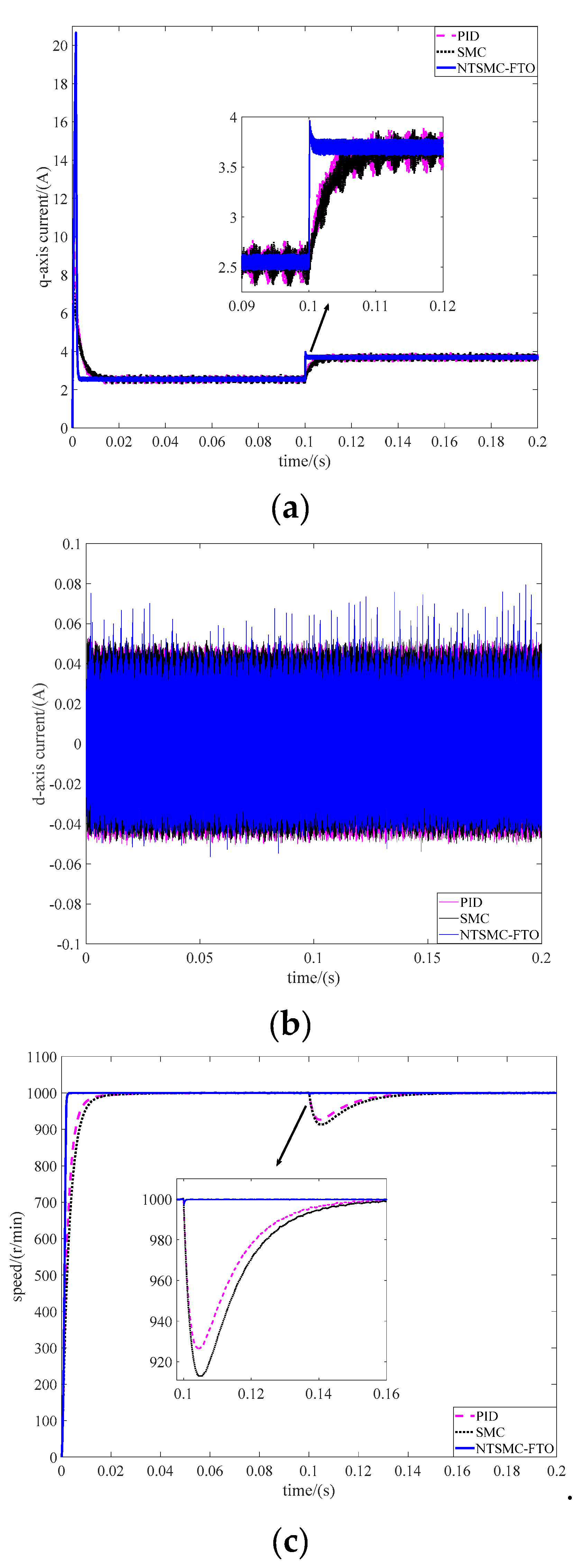
Case II: Load torque is changed suddenly. The load torque has a sudden change from T L = 0   N m to T L = 0.1   N m at t = 0.1   s . Figure 3a–c, are ω , i q , i d response curves of load torque sudden change, respectively. When the load torque changed suddenly, the speed of NTSMC-FTO is decreased by 2.5 r/min (0.25%), while SMC and PID are 87 r/min (8.7%) and 74 r/min (7.4%), respectively. The recovery time of NTSMC-FTO, SMC and PID to 1000 r/min are 0.0004s, 0.06s and 0.06 s, respectively. The comparative simulation results of load changed suddenly can be seen in Table 6.
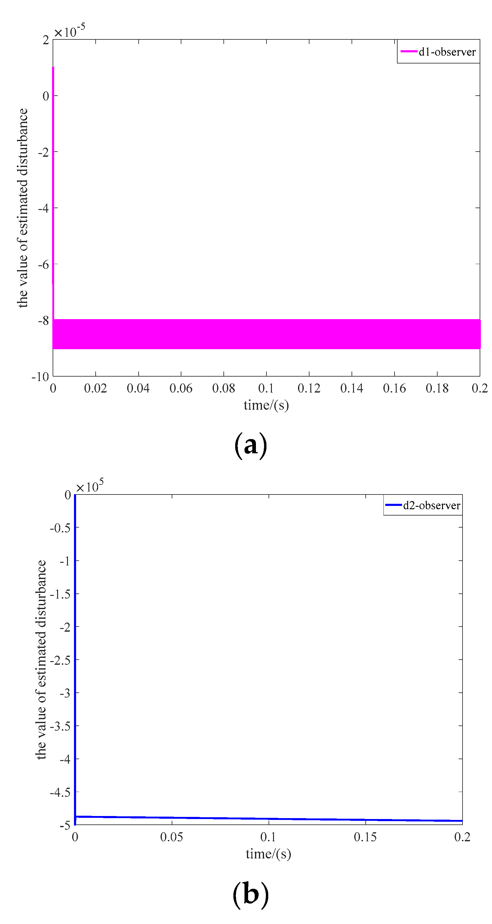
Figure 4a,b are disturbance d 1 and disturbance d 2 curves estimated by the finite time observers, respectively.
It can be concluded that compared with the traditional SMC and PID, the NTSMC-FTO proposed in this paper, which put the speed and current in one loop to regulate, has a faster tracking speed and a better disturbance rejection performance, demonstrating that the proposed method in this paper has strong robustness.

5. Conclusions

In this paper, a novel speed-current single-loop controller for the PMSM drive system has been proposed. Simulations have verified that compared with the cascade PID and cascade SMC method, the proposed method has a faster start up response and a better disturbance rejection performance. The disturbance can be accurately estimated and compensated by the proposed disturbance observer. Future research can be carried out from the state constraint of the proposed method to reduce the q-axis transient current and improve the safety of the system.

Author Contributions

This is a joint work and the authors were in charge of their expertise and capability: Y.W. (Yao Wang) for investigation and analysis; H.Y. for funding support; Z.C., Y.W. (Yuchen Wang), and Y.L. for manuscript revision.

Funding

This research was supported by National Natural Science Foundation of China (NSFC) under Grant 41576096.

Acknowledgments

The authors would like to express their gratitude to all those who helped them during the writing of this paper. And the authors would like to thank the reviewers for their valuable comments and suggestions.

Conflicts of Interest

The authors declare no conflict of interest.

References

  1. Lara, J.; Xu, J.; Chandra, A. Effects of Rotor Position Error in the Performance of Field Oriented Controlled PMSM Drives for Electric Vehicle Traction Applications. IEEE Trans. Ind. Electron. 2016, 63, 1. [Google Scholar] [CrossRef]
  2. Kommuri, S.K.; Defoort, M.; Karimi, H.R.; Veluvolu, K.C. A Robust Observer-Based Sensor Fault-Tolerant Control for PMSM in Electric Vehicles. IEEE Trans. Ind. Electron. 2016, 63, 7671–7681. [Google Scholar] [CrossRef]
  3. Liu, H.X.; Li, S.H. Speed control for PMSM servo system using predictive functional control and extended state observer. IEEE Trans. Ind. Electron. 2012, 59, 1171–1183. [Google Scholar] [CrossRef]
  4. Chaoui, H.; Khayamy, M.; Aljarboua, A.A. Adaptive Interval Type-2 Fuzzy Logic Control for PMSM Drives with a Modified Reference Frame. IEEE Trans. Ind. Electron. 2017, 64, 3786–3797. [Google Scholar] [CrossRef]
  5. Valente, G.; Formentini, A.; Papini, L.; Gerada, C.; Zanchetta, P. Performance improvement of bearingless multisector PMSM with optimal robust position control. IEEE Trans. Power Electron. 2019, 34, 3575–3585. [Google Scholar] [CrossRef]
  6. Sun, Z.X.; Li, S.H.; Wang, J.G.; Zhang, X.H.; Mo, X.H. Adaptive composite control method of permanent magnet synchronous motor systems. Trans. Inst. Meas. Control 2018, 11, 3345–3357. [Google Scholar] [CrossRef]
  7. Yu, J.; Shi, P.; Zhao, L. Finite-time command filtered backstepping control for a class of nonlinear systems. Automatica 2018, 92, 173–180. [Google Scholar] [CrossRef]
  8. Liang, W.; Fei, W.; Luk, P.C.-K. An Improved Sideband Current Harmonic Model of Interior PMSM Drive by Considering Magnetic Saturation and Cross-Coupling Effects. IEEE Trans. Ind. Electron. 2016, 63, 4097–4104. [Google Scholar] [CrossRef] [Green Version]
  9. Ren, H.P.; Liu, D. Nonlinear feedback control of chaos in permanent magnet synchronous motor. IEEE Trans. Circuits Syst. II Express Briefs 2016, 53, 45–50. [Google Scholar]
  10. Formentini, A.; Trentin, A.; Marchesoni, M.; Zanchetta, P.; Wheeler, P. Speed Finite Control Set Model Predictive Control of a PMSM Fed by Matrix Converter. IEEE Trans. Ind. Electron. 2015, 62, 6786–6796. [Google Scholar] [CrossRef]
  11. Cheema, M.A.M.; Fletcher, J.E.; Farshadnia, M.; Xiao, D.; Rahman, M.F. Combined Speed and Direct Thrust Force Control of Linear Permanent-Magnet Synchronous Motors with Sensorless Speed Estimation Using a Sliding-Mode Control with Integral Action. IEEE Trans. Ind. Electron. 2017, 64, 3489–3501. [Google Scholar] [CrossRef]
  12. Lang, X.Y.; Yang, M.; Xu, H.D.; Long, J.; Xu, D.G. A non-cascade predictive speed and current controller with PWM modulation for PMSM. In Proceedings of the IECON 2016-42nd Annual Conference of the IEEE Industrial Electronics Society, Florence, Italy, 23–26 October 2016. [Google Scholar]
  13. Guo, T.L.; Sun, Z.X.; Wang, X.Y.; Li, S.H.; Zhang, K.J. A simple current-constrained controller for permanent-magnet synchronous motor. IEEE Trans. Ind. Inform. 2019, 15, 1486–1495. [Google Scholar] [CrossRef]
  14. Yan, Y.; Yang, J.; Sun, Z.; Zhang, C.; Li, S.; Yu, H. Robust Speed Regulation for PMSM Servo System with Multiple Sources of Disturbances via an Augmented Disturbance Observer. IEEE/ASME Trans. Mechatron. 2018, 23, 769–780. [Google Scholar] [CrossRef]
  15. Liu, X.; Yu, H.; Yu, J.; Zhao, L. Combined Speed and Current Terminal Sliding Mode Control with Nonlinear Disturbance Observer for PMSM Drive. IEEE Access 2018, 6, 29594–29601. [Google Scholar] [CrossRef]
  16. Chaoui, H.; Khayamy, M.; Okoye, O. Adaptive RBF network based direct voltage control for interior PMSM based vehicles. IEEE Trans. Veh. Technol. 2018, 67, 5740–5749. [Google Scholar] [CrossRef]
  17. Zhang, X.G.; He, Y.K. Direct voltage-selection based model predictive direct speed control for PMSM drives without weighting factor. IEEE Trans. Power Electron. 2019, 34, 7838–7851. [Google Scholar] [CrossRef]
  18. Preindl, M.; Bolognani, S. Model predictive direct speed control with finite control set of PMSM drive systems. IEEE Trans. Power Electron. 2013, 28, 1007–1015. [Google Scholar] [CrossRef]
  19. Smidl, V.; Janous, S.; Adam, L.; Peroutka, Z. Direct Speed Control of a PMSM Drive Using SDRE and Convex Constrained Optimization. IEEE Trans. Ind. Electron. 2018, 65, 532–542. [Google Scholar] [CrossRef]
  20. Liu, B.; Zhou, B.; Ni, T.H. Principle and stability analysis of an improved self-sensing control strategy for surface-mounted PMSM drives using second-order generalized integrators. IEEE Trans. Energy Convers. 2018, 33, 126–136. [Google Scholar] [CrossRef]
  21. Mynar, Z.; Veselý, L.; Vaclavek, P. PMSM Model Predictive Control with Field-Weakening Implementation. IEEE Trans. Ind. Electron. 2016, 63, 5156–5166. [Google Scholar] [CrossRef]
  22. Liu, J.; Li, H.W.; Deng, Y.T. Torque ripple minimization of PMSM based on robust ILC via adaptive sliding mode control. IEEE Trans. Power Electron. 2018, 33, 3655–3671. [Google Scholar] [CrossRef]
  23. Tarczewski, T.; Grzesiak, L.M. Constrained state feedback speed control of PMSM based on model predictive approach. IEEE Trans. Ind. Electron. 2016, 63, 3867–3875. [Google Scholar] [CrossRef]
  24. Wang, W.-C.; Liu, T.-H.; Syaifudin, Y. Model Predictive Controller for a Micro-PMSM-Based Five-Finger Control System. IEEE Trans. Ind. Electron. 2016, 63, 3666–3676. [Google Scholar] [CrossRef]
  25. Xia, C.; Li, S.; Shi, Y.; Zhang, X.; Sun, Z.; Yin, W. A Non-Smooth Composite Control Approach for Direct Torque Control of Permanent Magnet Synchronous Machines. IEEE Access 2019, 7, 45313–45321. [Google Scholar] [CrossRef]
  26. Zhang, G.Q.; Wang, G.L.; Yuan, B.H. Active disturbance rejection control strategy for signal injection-based sensorless IPMSM drives. IEEE Trans. Transp. Electrif. 2018, 1, 330–339. [Google Scholar] [CrossRef]
  27. Li, S.H.; Zhou, M.M.; Yu, X.H. Design and Implementation of terminal sliding mode control method for PMSM speed regulation system. IEEE Trans. Ind. Inform. 2013, 9, 1879–1891. [Google Scholar] [CrossRef]
  28. Li, S.H.; Wu, C.; Sun, Z.X. Design and implementation of clutch control for automotive transmissions using terminal-sliding-mode control and uncertainty observer. IEEE Trans. Veh. Technol. 2016, 65, 1890–1898. [Google Scholar] [CrossRef]
  29. Du, H.B.; Chen, X.P.; Wen, G.H.; Yu, X.H.; Lü, J.H. Discrete-time fast terminal sliding mode control for permanent magnet linear motor. IEEE Trans. Ind. Electron. 2018, 65, 9916–9927. [Google Scholar] [CrossRef]
  30. Wu, F.; Li, P.; Wang, J. FO improved fast terminal sliding mode control method for permanent-magnet synchronous motor with FO disturbance observer. IET Control. Theory Appl. 2019, 13, 1425–1434. [Google Scholar] [CrossRef]
  31. Xu, W.; Junejo, A.K.; Liu, Y.; Islam, M.R. Improved Continuous Fast Terminal Sliding Mode Control with Extended State Observer for Speed Regulation of PMSM Drive System. IEEE Trans. Veh. Technol. 2019, in press. [Google Scholar] [CrossRef]
  32. Guo, L.; Wang, D.; Diao, L.; Peng, Z. Direct voltage control of stand-alone DFIG under asymmetric loads based on non-singular terminal sliding mode control and improved extended state observer. IET Electr. Power Appl. 2019, 13, 958–968. [Google Scholar] [CrossRef]
  33. He, L.; Wang, F.; Wang, J.; Rodriguez, J. Zynq Implemented Lunenberger Disturbance Observer Based Predictive Control Scheme for PMSM Drives. IEEE Trans. Power Electron. 2019, in press. [Google Scholar] [CrossRef]
  34. Yang, J.; Cui, H.Y.; Li, S.H.; Zolotas, A. Optimized active disturbance rejection control for DC-DC buck converters with uncertainties using a reduced-order GPI observer. IEEE Trans. Circuits Syst. I Regul. Pap. 2018, 65, 832–841. [Google Scholar] [CrossRef]
  35. An, H.; Liu, J.X.; Wang, C.H.; Wu, L.G. Disturbance observer-based anti-windup control for air-breathing hypersonic vehicles. IEEE Trans. Ind. Electron. 2016, 63, 3038–3049. [Google Scholar] [CrossRef]
  36. Hebertt, S.R.; Jesús, L.F.; Carlos, G.R.; Marco, A.C.O. On the control of the permanent magnet synchronous motor: An active disturbance rejection control approach. IEEE Trans. Control Syst. Technol. 2014, 22, 2056–2063. [Google Scholar]
  37. Chen, W.-H. Disturbance Observer Based Control for Nonlinear Systems. IEEE/ASME Trans. Mechatron. 2004, 9, 706–710. [Google Scholar] [CrossRef] [Green Version]
  38. Chen, M.-S.; Chen, C.-C. Robust Nonlinear Observer for Lipschitz Nonlinear Systems Subject to Disturbances. IEEE Trans. Autom. Control. 2007, 52, 2365–2369. [Google Scholar] [CrossRef]
  39. Khalil, H. Nonlinear Systems, 2nd ed.; Prentice-Hall: Upper Saddle River, NJ, USA, 1996. [Google Scholar]
  40. Hong, Y.; Huang, J.; Xu, Y. On an output feedback finite-time stabilization problem. IEEE Trans. Autom. Control 2001, 46, 305–309. [Google Scholar] [CrossRef]
  41. Shen, Y.J.; Huang, Y.H. Uniformly observable and globally Lipschitzian nonlinear systems admit global finite-time observers. IEEE Trans. Autom. Control 2009, 54, 2621–2625. [Google Scholar] [CrossRef]
  42. Perruquetti, W.; Floquet, T.; Moulay, E. Finite-Time Observers: Application to Secure Communication. IEEE Trans. Autom. Control. 2008, 53, 356–360. [Google Scholar] [CrossRef]
  43. Du, H.B.; Qian, C.J.; Yang, S.Z.; Li, S.H. Recursive design of finite time convergent observers for a class of time varying nonlinear systems. Automatica 2013, 49, 601–609. [Google Scholar] [CrossRef]
  44. Davila, J.; Fridman, L.; Levant, A. Second-order sliding-mode observer for mechanical systems. IEEE Trans. Autom. Control. 2005, 50, 1785–1789. [Google Scholar] [CrossRef]
  45. Lin, C.-K. Nonsingular Terminal Sliding Mode Control of Robot Manipulators Using Fuzzy Wavelet Networks. IEEE Trans. Fuzzy Syst. 2006, 14, 849–859. [Google Scholar] [CrossRef]
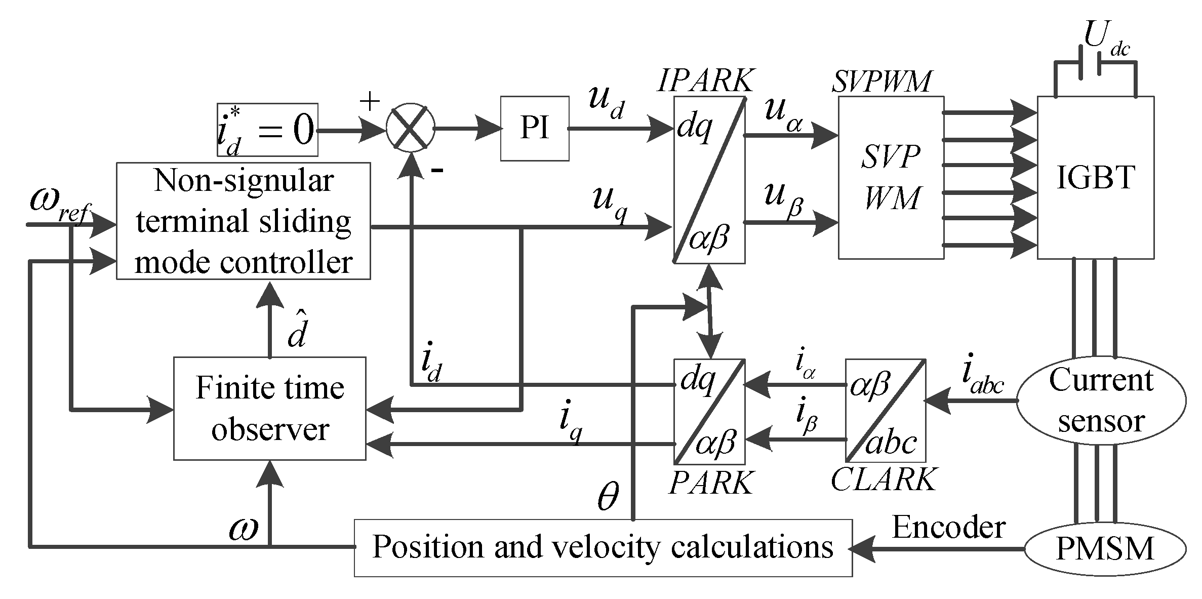
Figure 1. Permanent magnet synchronous motor (PMSM) control system based on the method designed in this paper.
Processes 07 00624 g001
Figure 2. Performance comparisons under the PID, permanent magnet synchronous motor (SMC) and NTSMC-FTO at the phase of startup. (a) Speed response curves. (b) d-axis current curves. (c) q-axis current curves.
Processes 07 00624 g002
Figure 3. Performance comparisons under the PID, SMC and NTSMC-FTO with sudden load torque change. (a) Speed response curves. (b) d-axis current curves. (c) q-axis current curves.
Processes 07 00624 g003
Figure 4. The estimated value based on the finite-time observer. (a)The estimated value of d1 based on the finite-time observer. (b)The estimated value of d2 based on the finite-time observer.
Processes 07 00624 g004
Table 1. Rated parameters of the permanent magnet synchronous motor (PMSM).
Rated PowerPN200W
line resistanceR0.33Ω
line inductanceL9 × 10−4H
magnetic polesnp4pairs
torque constantKt0.087N·m/A
rated powerUN36VAC
rated currentIN7.5A
rotor inertiaJ1.89 × 10−5kg·m2
rated speednN3000r/min
Table 2. The cascade PID controller.
DescriptionParameterValue
speed loop proportional gainK10.01
speed loop integral gainI10.95
speed loop proportional gainK250
speed loop integral gainI2100,000
current loop Id proportionalKp12000
current loop Id integral gainKI1100,000
Table 3. The cascade sliding mode control (SMC) controller.
DescriptionParameterValue
error gain of SMCc10.8
switch gain of SMCMu100
sliding mode surface gain of SMC κ 12
speed loop proportional gainK250
speed loop integral gainI2100,000
current loop Id proportionalKp12000
current loop Id integral gainKI110,000
Table 4. The proposed controller this paper.
DescriptionParameterValue
the power of NTSMCp37
the power of NTSMCq35
proportional gain of NTSMC η 5100
switch gain of NTSMC ε 200,000,000,000
the gain of observer1 λ 1 1,000,000
the gain of observer1 λ 2 10
the gain of observer2 λ ¯ 1 50,000,000
the gain of observer2 λ ¯ 2 500
current loop i d proportionalKp12000
current loop i d integral gainKI110,000
Table 5. The comparative simulation results of start up.
MethodReference SpeedTime to Reach Steady State
NTSMC-FTO1000 r/min0.0028 s
the cascade SMC1000 r/min0.045 s
the cascade PID1000 r/min0.045 s
Table 6. The comparative simulation results of load changed suddenly.
MethodReference SpeedDecreased Value of SpeedThe Recover Time of Steady State
NTSMC-FTO1000 r/min2.5 r/min0.0004 s
the cascade SMC1000 r/min87 r/min0.06 s
the cascade PID1000 r/min74 r/min0.06 s