Article

Technoeconomic Evaluation of a Process Capturing CO2 Directly from Air

by
Romesh Pramodya Wijesiri
1,2,
Gregory Paul Knowles
2,
Hasina Yeasmin
1,
Andrew Forbes Alexander Hoadley
1,* and
Alan Loyd Chaffee
2,*
1
Department of Chemical Engineering, 16 Alliance Lane, Clayton Campus, Monash University, Clayton, VIC 3800, Australia
2
School of Chemistry, 17 Rainforest Walk, Clayton Campus, Monash University, Clayton, VIC 3800, Australia
*
Authors to whom correspondence should be addressed.
Processes 2019, 7(8), 503; https://doi.org/10.3390/pr7080503
Submission received: 30 June 2019 / Revised: 26 July 2019 / Accepted: 28 July 2019 / Published: 2 August 2019
(This article belongs to the Collection Multi-Objective Optimization of Processes)

Abstract

:
Capturing CO2 directly from air is one of the options for mitigating the effects global climate change, and therefore determining its cost is of great interest. A process model was proposed and validated using laboratory results for adsorption/desorption of CO2, with a branched polyethyleneimine (PEI) loaded mesocellular foam (MCF) silica sorbent. The model was subjected to a Multi-Objective Optimization (MOO) to evaluate the technoeconomic feasibility of the process and to identify the operating conditions which yielded the lowest cost. The objectives of the MOO were to minimize the cost of CO2 capture based on a discounted cash flow analysis, while simultaneously maximizing the quantity of CO2 captured. This optimization identified the minimum cost of capture as 612 USD tonne−1 for dry air entering the process at 25 °C, and 657 USD tonne−1 for air at 22 °C and 39% relative humidity. The latter represents more realistic conditions which can be expected for subtropical climates. The cost of direct air capture could be reduced by ~42% if waste heat was utilized for the process, and by ~27% if the kinetics of the sorbent could be improved by a factor of two. A combination of both would allow cost reductions of ~54%.

1. Introduction

The increase in anthropogenic CO2 emissions has been identified as a main cause of global climate change. Close to half [1] of these emissions are accounted for by diffuse sources such as motor vehicles, homes and offices. Capturing these emissions at the source would require the fitting of capture systems to each of these, which would neither be economical, nor practical. Alternatively, the effect of these emissions could be compensated for with “Direct Air Capture” (DAC) systems, i.e., processes which capture CO2 directly from the atmosphere. The captured CO2 could either be sequestered or utilized for application in various industries [2]. The technologies evaluated for DAC include absorption with aqueous hydroxide solutions, adsorption with solid inorganic bases, and adsorption with solid-supported amines (SSA). A review of the studies done on DAC has been detailed in Sanz-Pérez et al. [3]. Of these technologies, adsorption with SSA has presented itself to be promising for DAC.
SSAs are a group of sorbents made of various amines, physically or chemically supported on porous solid materials. They are well suited for DAC applications, due to their high uptake capacity and selectivity, resilience to moisture which is present in air, and the possibility of regeneration under relatively mild conditions. While significant research has been done on SSA for DAC, its focus has mainly been on sorbent development. There have only been a few reports [4,5,6,7,8,9] on the energy requirements and the cost of capture of such systems, and there is significant discrepancy between their results. These reports [4,5,6,7,8,9] evaluated DAC systems which used temperature concentration swing adsorption (TCSA) [5,6], temperature vacuum swing adsorption (TVSA) [9] and steam-assisted temperature vacuum swing adsorption (S-TVSA) [4,7,8] type processes. For TCSA, after the CO2 is adsorbed on to the sorbent, the sorbent is heated and purged with a gas (steam in Krekel et al. [5] and Zhang et al. [6]) to effect desorption. In TVSA, desorption is achieved by heating the sorbent and applying a vacuum. S-TVSA is a hybrid of the two approaches, where in addition to applying heat and a vacuum, a steam purge is also used.
In two of the early studies, Kulkarni and Sholl [7] and Zhang et al. [6] carried out an economic analysis based only on the operating cost of the processes. They reported costs of CO2 capture of 43–494 [7] and 91–227 [6] USD tonne−1. Krekel et al. [5] expanded on the work carried out by Zhang et al. [6], and reported that once the capital expenses are included, the cost of capture would be increased significantly to 792–1200 USD tonne−1. Sinha et al. [4] estimated a cost of capture of 60–190 USD tonne−1.
Several companies are active in the field of DAC with SSA. The most well-known of these are Climeworks [10] and Global Thermostat [11]. The cost of capture reported for the operations of first-generation DAC system by Climeworks was estimated to be 600 USD tonne−1 [12]. This is an important benchmark, as it is based on a commercially operating system, as opposed to results of studies which are sensitive to the scope and assumptions used. Climeworks has further expressed their confidence in reducing this cost down to 200 USD tonne−1 by 2021, and down to 100 USD tonne−1 by 2030 [12]. Similarly, Global Thermostat expects a cost of capture of 100 USD tonne−1 for their first commercial DAC process [12]. Carbon Engineering [13] is another company which is developing a DAC process, although they focus on an aqueous hydroxide-based process. The projected cost of capture with this process has been reported to be 94–232 USD tonne−1 [14], but this process requires very high temperatures for regeneration of the sorbent.
In comparison, removing CO2 from air via afforestation and forest management has a cost of capture of 15–50 USD tonne−1 [15]. However, this approach carries a large land requirement, which would compete with the land available for food production. Moreover, the land available also enforces an upper limit on the scale at which CO2 can be removed. In comparison, CO2 removal by DAC faces less stringent limitations on the degree of possible scaling. However, it is important to stress that DAC is not envisioned to be an alternative for good forest management practices, but rather as a technology to supplement the rate of CO2 removal by the natural carbon cycle.
The energy requirements of the DAC processes in prior works, is largely accounted for by the thermal energy required for the desorption process. This mainly consists of the sensible heat required to heat up the sorbent to the desorption temperature, and the large heat of desorption for CO2. When adsorption is considered under humid conditions, the heat of desorption of water, which gets co-adsorbed on SSA, adds to the thermal energy demand [9]. Another big contributor to the energy consumption is that needed for pushing air through the air-sorbent contactors. Due to the low concentration of CO2 in air, large amounts of air need to be processed to capture the CO2. This results in large energy requirements, even for low pressure drop contactor configurations as are described in some studies [4,7].
It was previously reported [16] that branched polyethyleneimine (PEI) loaded mesocellular foam (MCF) silica sorbent in pelletized form is promising for CO2 adsorption under DAC conditions. The study identified that while low temperatures were better for the thermodynamics of the reaction between the CO2 and amine sites, the uptake of CO2 was limited by diffusional resistances in the sorbent. In contrast, higher temperatures allowed for better diffusion of CO2, but the thermodynamics were less favored. The amount of CO2 adsorbed by the sorbent was determined by the combined effect of these two factors. Due to the large diffusional resistances of the sorbent studied, the highest uptake was achieved under relatively warm conditions (46 °C). The study further identified that low levels of moisture in the gas (0.5 to 2% mol-H2O), enhanced the CO2 uptake by up to 53%.
The same sorbent was evaluated using a S-TVSA adsorption/desorption cycle [17]. It was identified that substantial CO2 desorption could be achieved with mild vacuum levels (12 to 56 kPa abs), and temperatures (70 to 100 °C). This indicated that the process could benefit from a reduced electrical energy demand for vacuum generation and a lower capital cost owing to the use of smaller vacuum pumps. It was further noted that as desorption is possible at relatively low temperatures, the thermal energy requirement could be supplied with low grade heat. The desorption conditions (pressure, temperature, steam flow rate) were seen to have a significant effect on the desorption performance. Moreover, it was identified that while the presence of moisture enhanced CO2 adsorption, it also resulted in a significant uptake of H2O, which increased the thermal energy demand for the desorption stage.
Building on this prior work, the present study aimed to (1) identify operating conditions which yield the lowest cost of DAC, (2) determine the relative effects of varying operating conditions on its technoeconomic performance and (3) identify promising directions for research on sorbent development that could foster further cost reduction for DAC.
To address the first two aims, a DAC technoeconomic model was developed based on the results of laboratory scale experimental data [17]. Next, the process model was subjected to a Multi-Objective Optimization (MOO) to minimize the cost of capture, while simultaneously maximizing the amount of CO2 captured. In contrast to prior studies [4,5,6,7] which fixed on particular process conditions, the present study considers a range of conditions, seeking to minimize the cost. Moreover, adsorption from dry versus and humid air was compared, to evaluate the effect of the water, which co-adsorbs, on the process. Previous technoeconomic studies do not appear to have addressed this aspect [4,5,6,7]. The final aim was addressed through the use of case studies exploring the relative effect that sorbent modifications could have on the cost of capture.

2. Methods

2.1. Adsorption/Desorption Model

To develop a process model and evaluate the economics, the laboratory scale data was fitted to a simplified heat and mass transfer model, which accurately predicts the performance of the sorbent. In this simplified model, it is assumed that the adsorption bed has no concentration or temperature gradients in either the radial or the axial direction. With this assumption, it is possible to develop a sorbent column transport model, without using isotherm data. This simple empirical model is used to simulate the adsorption/desorption behavior of the sorbent for a specific sorbent bed configuration. The model is limited to predicting the performance with a single bed thickness and is not able to account for different bed thicknesses, as these would require isotherm and bed dispersion experimental data. The following assumptions were made to develop the model:
  • Ideal gas law is assumed for all gases;
  • “Air” in this study comprises of 420 ppm CO2 in N2;
  • Only CO2 and H2O interact with the sorbent;
  • Adsorption and desorption occur under isobaric conditions;
  • There are no heat losses to the surroundings.

2.1.1. CO2/H2O Mass Transfer Kinetics

The mass transfer rate of CO2 and H2O from/to the sorbent was approximated by the linear driving force (LDF) model [18,19] (Equation (1)) where d q d t is the mass transfer rate (mol kg-sorbent−1 s−1), q e q is the equilibrium adsorbed amount of CO2 or H2O (mol kg−1) under the specified process condition, and q t is the amount adsorbed on the sorbent (mol kg−1) at time t. k is the LDF mass transfer coefficient (s−1) which is a lumped parameter accounting for all the resistances to mass transfer. i refers to the components H2O or CO2 and j refers to ads (adsorption) or des (desorption).
d q i , j d t = k i , j ( q e q , i , j q t , i , j )
As the desorption kinetics are affected by the temperature and the partial pressure of CO2, the LDF mass transfer coefficient, k C O 2 , d e s , was expanded to account for temperature in Equation (2) and partial pressure in Equation (3). Due to the lack of isotherm data, an empirical relationship (Equation (3)) with the steam flow rate and the desorption pressure was used to predict the effect of the partial pressure of CO2 on the desorption kinetics. In Equation (2), E a is the activation energy (J mol−1), R is the gas constant (J mol−1 K−1) and T is temperature (°C). k 0 , C O 2 is a constant (s−1) which follows an empirical relationship with the pressure (kPa abs), P, and steam flow rate (kg-steam h−1 kg-sorbent−1), m ˙ s t e a m , according to Equation (3). k1–5 are empirical constants.
k C O 2 , d e s = k 0 , C O 2 e   E a , C O 2 R ( T + 273 )
k 0 , C O 2 = k 1 ( k 2 e   m ˙ s t e a m k 3 ) ( k 4 P + k 5 )
For H2O mass transfer in the desorption stage, the LDF mass transfer coefficient, k H 2 O , d e s , was expanded according to Equation (4), to account for the effect of temperature on the kinetics.
k H 2 O , d e s = k 0 , H 2 O e   E a , H 2 O   R ( T + 273 )
For the adsorption stage, this study only considered a single adsorption temperature (27 °C). Therefore, the LDF constants, k H 2 O , a d s and k C O 2 , a d s , were estimated as fixed values and not as relationships to the process conditions.

2.1.2. Equilibrium Model for H2O Uptake During the Desorption Stage

The equilibrium uptake of water by the sorbent under the desorption conditions were fitted to a Freundlich isobar equation [20] (Equations (5) and (6)), where qeq is the equilibrium adsorbed amount of water (mol kg−1), R is the gas constant (J mol−1 K−1), T is the temperature (°C) and P is the pressure (kPa abs). K0 (mol kg−1 kPa−1/n0), α and A0 (J mol−1) are constants.
q e q , H 2 O , d e s = K 0 e   α R ( T + 273 ) A 0 P 1 n 0
n 0 = A o R ( T + 273 )

2.1.3. Heat Transfer Model

The heat transfer to/from the sorbent was modelled according to the energy balance given by Equation (7), where m s o r b e n t is the mass of sorbent (kg), C p , s o r b e n t is the specific heat capacity of the sorbent (J kg−1 °C−1), T b e d is the bed temperature (°C), t is time (s), T h e a t / c o o l is the temperature (°C) of the medium used to heat up or cool down the sorbent bed, U is the overall heat transfer coefficient (W m−2 °C−1) between the heating/cooling medium and the sorbent bed, A is the heat transfer area of the bed (m2),   m ˙ is mass flow rate (kg s−1) and h is the specific enthalpy (J kg−1).
m s o r b e n t C p , s o r b e n t d T b e d d t = U A ( T h e a t / c o o l T b e d ) + m ˙ i n , H 2 O h i n , H 2 O m ˙ o u t , H 2 O h o u t , H 2 O + m ˙ i n , C O 2 h i n , C O 2 m ˙ o u t , C O 2 h o u t , C O 2
The specific enthalpies of the components were calculated according to Equation (8) where H a d s is the heat of adsorption (J kg−1), Cp is the specific heat capacity (J kg−1 °C−1), T is the temperature (°C) and T r e f is a reference temperature (°C), taken to be 50 °C for this study. H a d s , C O 2 for this type of sorbent was previously reported to be 2270 kJ kg−1 [21] and C p , s o r b e n t was measured to be 2 kJ kg−1 °C−1 using a SETARAM micro DSC III. H a d s , H 2 O of 2611 kJ kg−1 was adopted from Wurzbacher et al. [9].
h i = H a d s , i + C p , i ( T T r e f )
i refers to the component CO2 or H2O.

2.1.4. Experimental Validation of Adsorption/Desorption Model and Parameter Estimation

The experimental data for the validation of the adsorption/desorption model was acquired using the procedure described in Wijesiri et al. [17].
The parameters for Equation (1) for the mass transfer kinetics in the adsorption stage ( k i , a d s and q e q , i , a d s ) were determined by doing a least squares regression fit of the LDF model on the experimental data for CO2/H2O uptake ( q t , a d s ) from 420 ppm CO2 at 27 °C, under dry conditions and with 1% mol-H2O. The experimental data showed minimal changes in temperature (≤ 1 °C) for both cases, so the adsorption stage was assumed to be isothermal.
For the desorption stage, the CO2 mass transfer kinetics were experimentally determined for the range of desorption conditions discussed in this study. Essentially all the CO2 was desorbed [17] and therefore the equilibrium adsorbed amount ( q e q , C O 2 , d e s term in Equation (1)) was assumed to be 0.00 mol kg−1 for all the desorption conditions. The constants E a , C O 2 and k 1 to k 5 , were estimated by least squares regression of the experimental CO2 desorption data ( q t , d e s ).
Similarly, the parameters for the Freundlich isobar (Equations (5) and (6)) were estimated by least squares regression of the experimental equilibrium H2O uptake data.
As it was not possible to obtain data on the H2O mass transfer kinetics during the desorption stage with the experimental set up used, it had to be approximated by using the bed temperature data and the heat transfer model (Equation (7)). To do this, the heat transfer coefficient from the oven to the sorbent bed, U was obtained by fitting the heat transfer model of the clean sorbent bed, Equation (7), (with no CO2 or H2O adsorbed) against the experimental bed temperature data ( T b e d ).
The mass transfer kinetics of H2O during the desorption stage were determined by coupling the mass transfer model (Equations (1)–(4)) with the heat transfer model (Equation (7)). The m ˙ o u t , H 2 O term in Equation (7) was defined according Equation (9), where M W H 2 O is the molar mass of H2O (kg mol−1)
m ˙ o u t , H 2 O = m ˙ i n , H 2 O d q H 2 O d t × m s o r b e n t × M W H 2 O
k 0 , H 2 O and E a , H 2 O in Equation (4) were determined by least squares regression fitting Equation (7) to the experimental bed and oven temperature data with the m ˙ i n , C O 2 , m ˙ o u t , C O 2 and m ˙ i n , H 2 O data from the experiments.

2.2. Process Model and Economic Model

2.2.1. Air-Sorbent Contactor Configuration

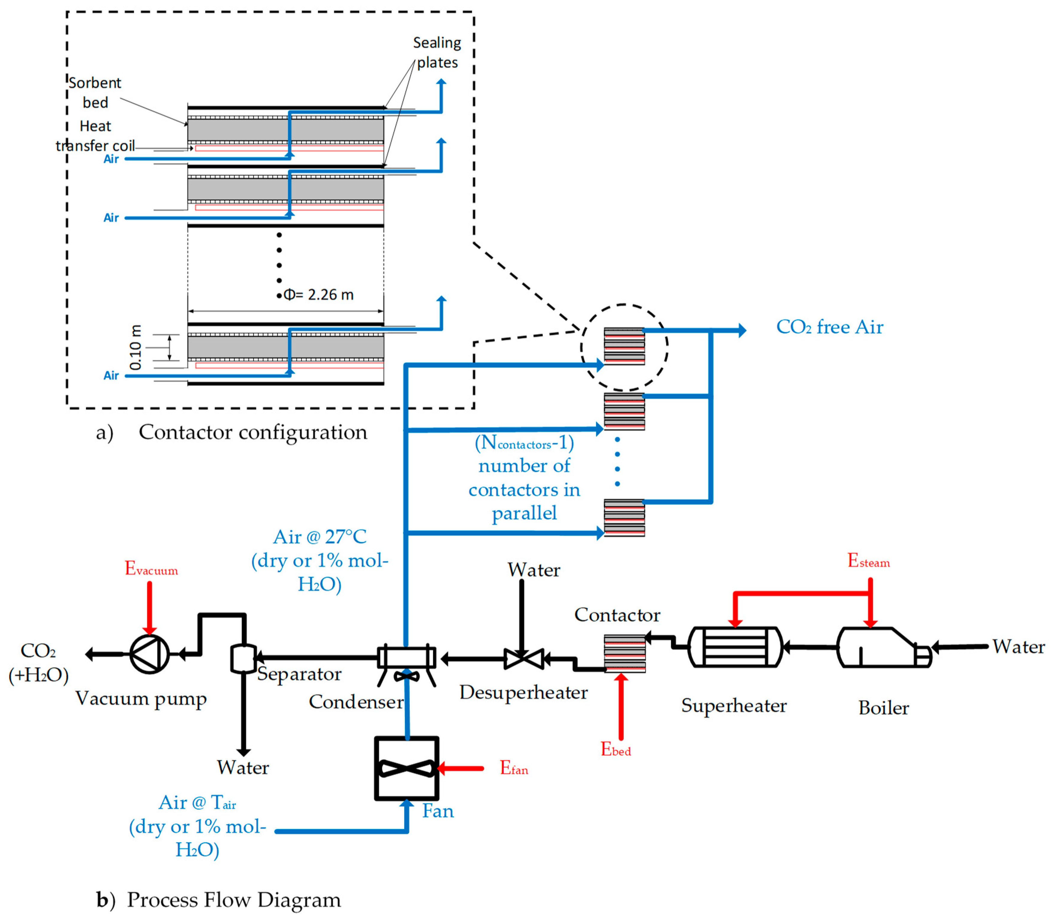
For the scaled-up process, an air-sorbent contact similar to that described in Patent WO2014170184A1 [22] was considered. This consists of a series of stacked thin cylindrical adsorption beds contained in a larger contactor (see Figure 1a). In such a contactor, air flows in through the inlet on one side, flows up across the thickness of the sorbent bed, and exits through another side of the contactor. The heating and cooling of the bed is envisioned to be done by heat transfer coils directly under the sorbent beds. When scaling up, it was assumed that the ratio of heat transfer to mass of sorbent would be kept the same as the lab scale experimental set up used. The beds were 2.26 m in diameter ( d b e d , c o n t a c t o r ) which is close to the maximum recommended for adsorption beds [23]. The height ( H b e d , c o n t a c t o r ) was 0.10 m; this being the same height as the laboratory scale experiments. The void factor ( ϵ ) of the beds was assumed to be 0.5. It was also assumed that the diameter of the sorbent pellets, d p e l l e t , used in the contactor would be the same as the lab scale set up (1.8 mm). These dimensions correspond to 250 kg of sorbent per bed. For the current study, a contactor with 16 beds, with a total of 4000 kg of sorbent per contactor, was considered.

2.2.2. Process Description

The process model considers two scenarios in order to determine the effect of moisture inherent in air collected from the surroundings: adsorption from dry air and adsorption from air with a moisture content of 1% mol-H2O. In both scenarios, the adsorption is carried out at 27 °C. These two scenarios are referred to as the “dry case” and “humid case”.
A schematic of the process considered for the current study is depicted in Figure 1b. The process consists of multiple contactors adsorbing CO2 from air in parallel, and a single contactor desorbing CO2. In the adsorption stage, the incoming air is heated up to the adsorption temperature (27 °C) and pushed through the contactors using a fan. The air is heated, as it was previously discovered [16] that higher temperatures led to higher CO2 uptake, due to improved diffusion kinetics. Heating the air also provides the cooling necessary for the condensation of steam in the desorption stage. A previous study [16] reported that this sorbent had the highest CO2 uptake at 46 °C. However, as this temperature corresponds to unrealistically warm climates, and heating the air to 46 °C would require a significant amount of energy, a milder adsorption temperature of 27 °С is considered for the current study.
The temperature at which the air could enter the process, T a i r (°C), was calculated according to Equation (10), where Q c o n d e n s e r , is the cooling duty of the condenser (W) (refer Section S1 of the Supplementary Information), m ˙ a i r is the mass flow rate of air per contactor (kg s−1), C p is the specific heat capacity of air (J kg−1 °C−1) and N c o n t a c t o r s is the number of contactors in the system. The relative humidity (RH) values corresponding to 1% mol-H2O for the humid case were calculated according to Equation (11), where P a i r is the pressure of the air which is assumed to be 101 kPa abs, and p s a t , H 2 O is the saturation vapour pressure of water, calculated according to the Antoine correlation [24].
T a i r = 27   Q c o n d e n s e r m ˙ a i r C p . a i r × ( N c o n t a c t o r s 1 )
R H = P a i r × 1 % P s a t , H 2 O
In the desorption stage, water is boiled and superheated to produce steam, which is then passed through the contactor. Downstream of the contactor, the steam is desuperheated via the addition of water, and passed through the condenser, which cools the CO2/H2O mixture down to 45 °C. Following this, the condensate is separated from the gas and returned to the boiler. The gas stream from the condenser, consisting of CO2 saturated with H2O, is compressed to atmospheric pressure using the vacuum pump. The calculations for the unit operations in the process are described in S1 in the Supplementary Information.
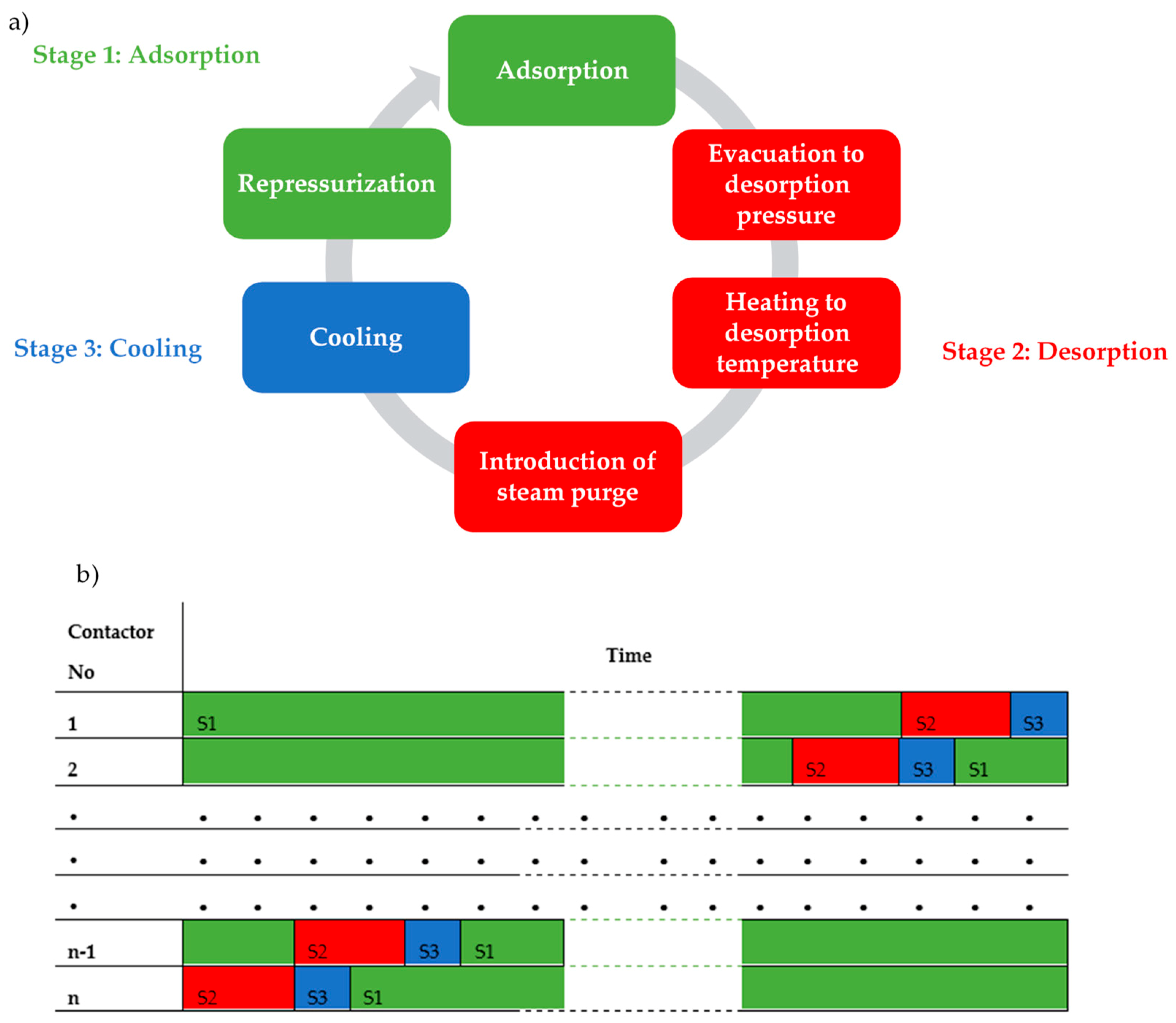
The adsorption/desorption cycle the contactors are subjected to is shown in Figure 2a. The cycle is split into three stages. Firstly, the contactor goes through the adsorption stage, until a predetermined amount of CO2 ( q a d s ) is adsorbed into the bed. The desorption stage starts by first evacuating the contactor to the desorption pressure and heating up the sorbent to the desorption temperature. The heating is provided by a heat transfer fluid, at 10 °C higher than the desorption temperature, passing through the heating coils shown in Figure 1. After the sorbent is heated to just above the steam dew point temperature, the steam purge is started. Following the introduction of steam, heat is continuously supplied to the bed, to maintain the desorption temperature, for the remainder of the desorption stage. The desorption stage ends after a predetermined amount of CO2 ( q d e s ) is desorbed. Following this, the bed goes into the cooling stage, where the bed is cooled down to the adsorption temperature by passing water, at 25 °C, through the cooling coils. Finally, the contactor is re-pressurized and goes back into the adsorption stage. For this study, it was assumed that the evacuation and re-pressurization steps would take negligible time. The operational sequence of the contactors is shown in Figure 2b, which shows how the contactors are subjected to the cycles, with one bed in desorption at all times.

2.2.3. Energy Consumption

The energy requirements considered for the evaluation are the electrical energy required to operate the fan (Efan) in the adsorption stage and the vacuum pump (Evacuum) in the desorption stage, and the thermal energy required to heat the sorbent beds (Ebed) and to produce steam (Esteam). The methods for calculating these are presented in Section S2 of the Supplementary Information.

2.2.4. Capital Cost

The purchased equipment costs of the major equipment were estimated using cost correlations [23,25,26]. The cost correlations were adjusted for inflation using the chemical engineering plant cost index (CEPCI). The total plant cost was calculated by accounting for insulation, piping, instrumentation, electrical work, civil and structures, and lagging [27]. The detailed calculations are included in Section S3 of the Supplementary Information.

2.2.5. Operating Cost

The energy requirements of the process were assumed to be met by a solar thermal hot water system and a solar photovoltaic system to minimize the CO2 emissions from the process. The energy costs were taken to be 50 USD MWh−1 for thermal energy [28] and 100 USD MWh−1 for electrical energy [29]. The cost of water was taken to be 3 USD m−3 [30] and the annual maintenance was assumed to be 2% of the total plant cost [27]. The sorbent was assumed to cost 8.1 USD kg−1 and have a lifetime of 4 years. The cost of the sorbent was estimated by calculating the cost of the raw materials required and multiplying it by a factor of 3 to account for the production costs. More details are included in Section S4 of the Supplementary Information.

2.2.6. Cost of Capture

The cost of capture of CO2 ( C C O 2 ) in USD tonne−1 is calculated from a discounted cash flow calculation to obtain a zero Net Present Value (NPV) at the end of the project life using Equation (12), where C C O 2 is the cost of capture (USD tonne−1), C p l a n t , C a n n u a l   o p e x and C s o r b e n t are the capital cost of the plant, annual operating cost, and the cost of sorbent, respectively.
C R is the annual capture rate (tonne yr−1) as calculated according to Equation (13), where q d e s is the amount of CO2 desorbed (referred to as the extent of desorption from hereon) per cycle (mol kg−1), m s o r b e n t is the mass of sorbent in a single contactor (kg), M W C O 2 is the molar mass of CO2 (kg mol−1), N c o n t a c t o r s is the number of contactors in the system, and t c y c l e is the total cycle time (h). The process was assumed to run 360 days a year for 24 h a day. More details are given in Section S5 of the Supplementary Information. For the NPV analysis, the plant operating lifetime is 20 years and a discount rate of 10% is used.
C C O 2 = ( C p l a n t + C a n n u a l   o p e x   x = 1 20 1 ( 1 + 0.1 ) x + C s o r b e n t y = 0 , 4 , , 16 , 20 1 ( 1 + 0.1 ) y ) C R × x = 1 20 1 ( 1 + 0.1 ) x
C R = ( q d e s × m s o r b e n t × M W C O 2 × N c o n t a c t o r s ) t cycle × 8.64   h   y e a r 1   t   k g 1

2.3. Multi-Objective Optimization

To determine the preferred operating conditions which would result in the lowest cost of capture and the highest capture rate, a multi-objective optimization (MOO) was carried out on the process model using the MATLAB gamultiobj function. This uses a controlled, elitist genetic algorithm (a variant of NSGA-II [31]). The objectives for the MOO were to minimize ( C C O 2 ) and maximize ( C R ). The objectives, variables and the constraints of the MOO problem are listed in Table 1.
Additionally, the constraint in Equation (14) was enforced to ensure that all the contactors can be desorbed within a single cycle, where t a d s and t d e s are the durations of the adsorption and desorption stages (h) and N c o n t a c t o r s is the number of contactors in the system.
t a d s t d e s × ( N c o n t a c t o r s 1 )

2.4. Sensitivity Analysis

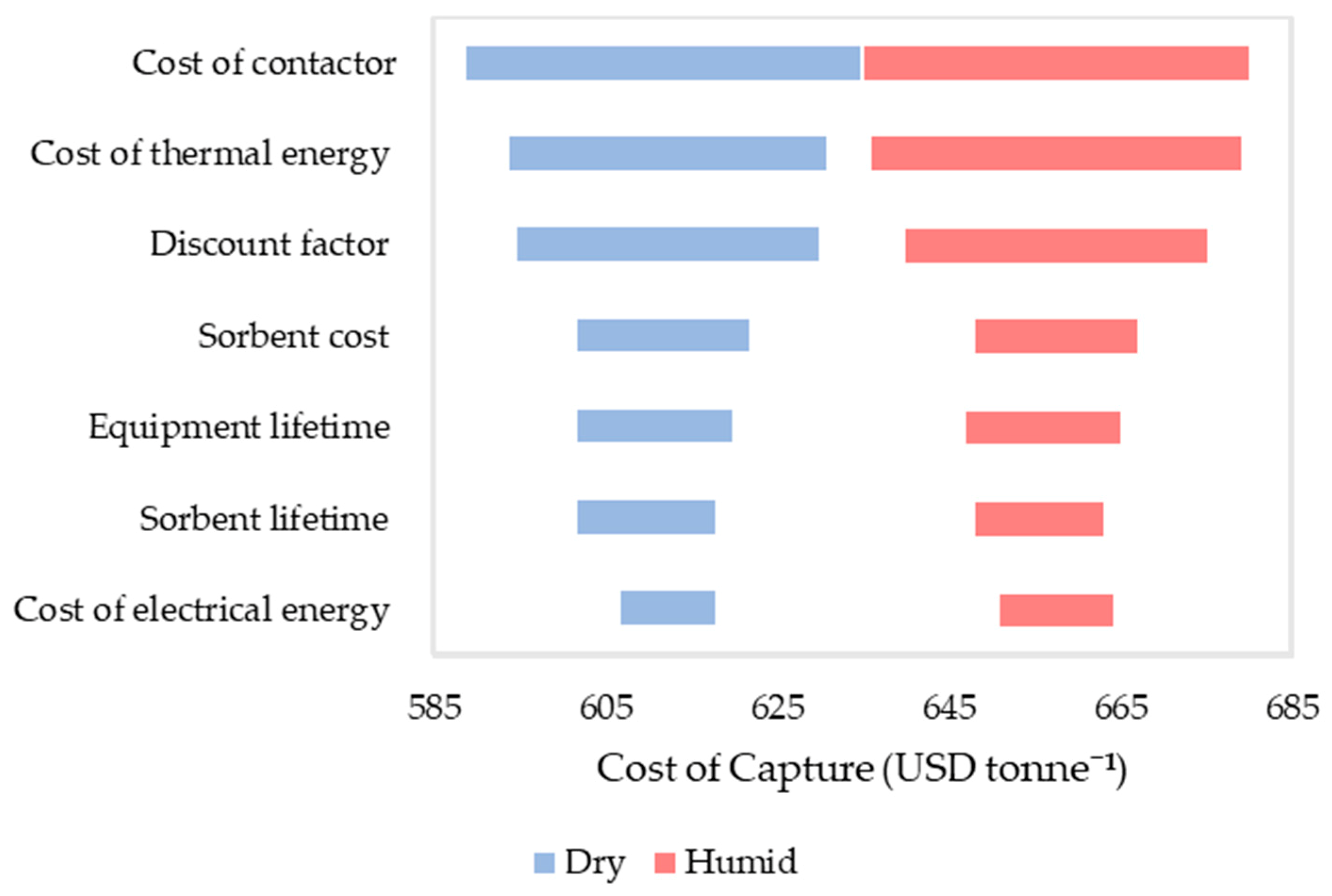
Two sensitivity analyses were carried out. Firstly, the sensitivity of the results of the cost of capture to some of the values in the model which carried uncertainty were tested. This was done by varying these values by ±10% from the original values and observing the change in the cost of capture in the lowest cost scenario. The values of interest chosen were cost of energy, cost of the contactor, discount rate, sorbent cost and lifetime and the plant lifetime.
Next, the sensitivity of the results to the MOO parameters used was tested. This was done by varying the parameters used for the original MOO.

3. Results of Model Validation and Parameter Estimation

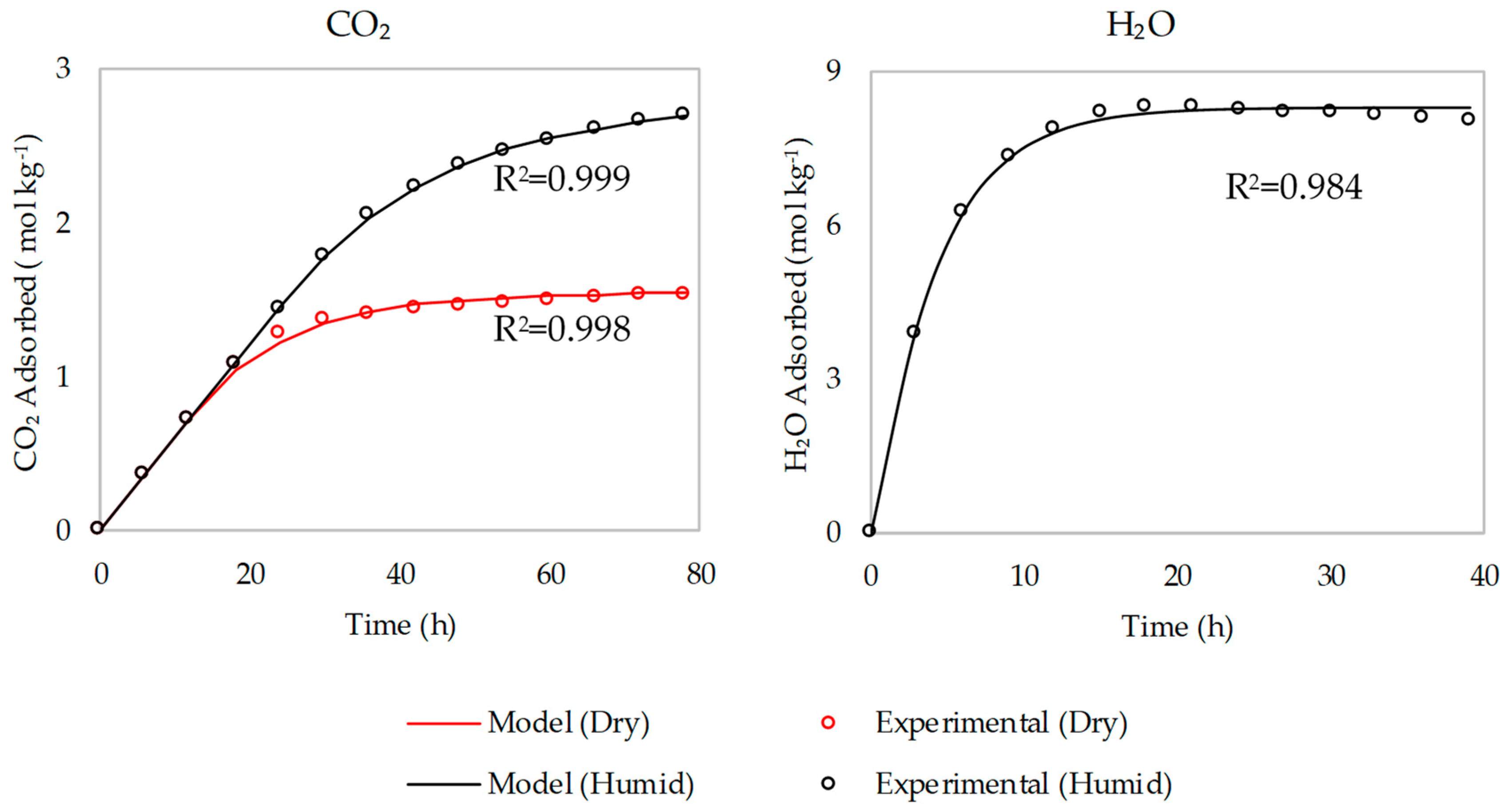
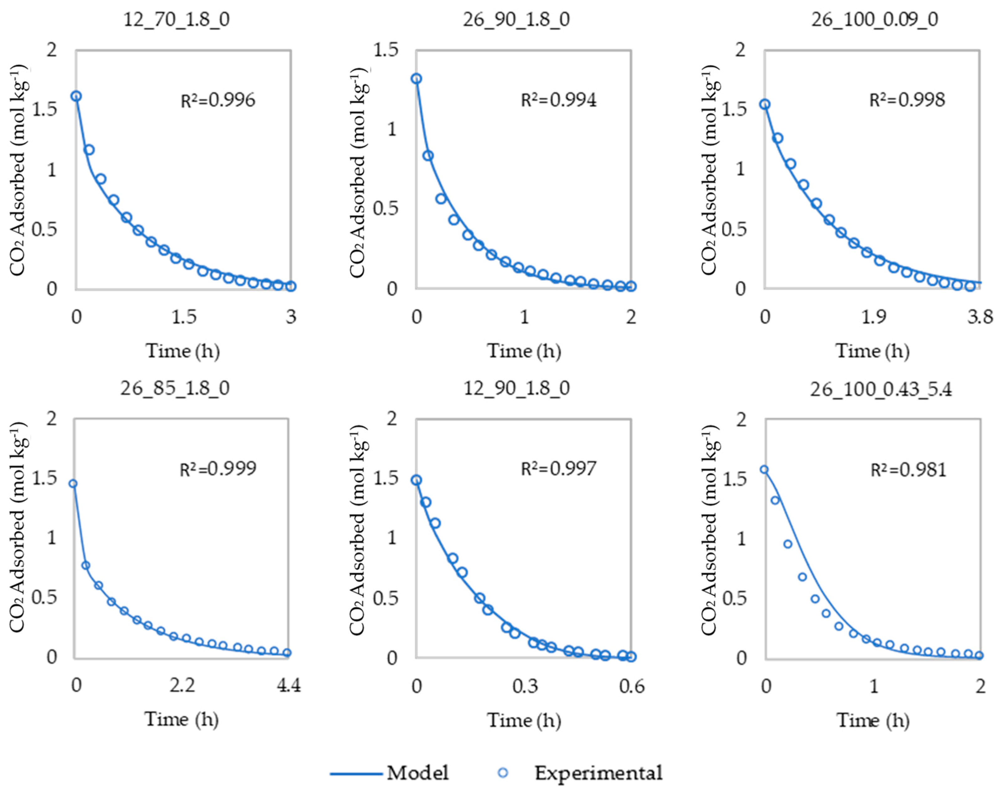
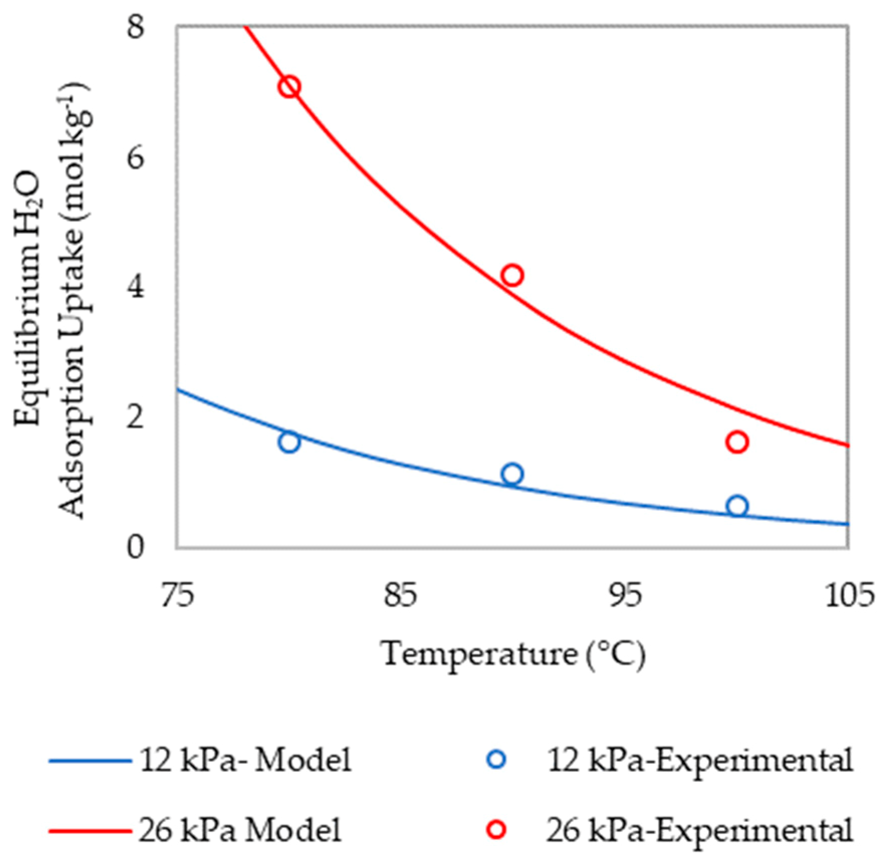
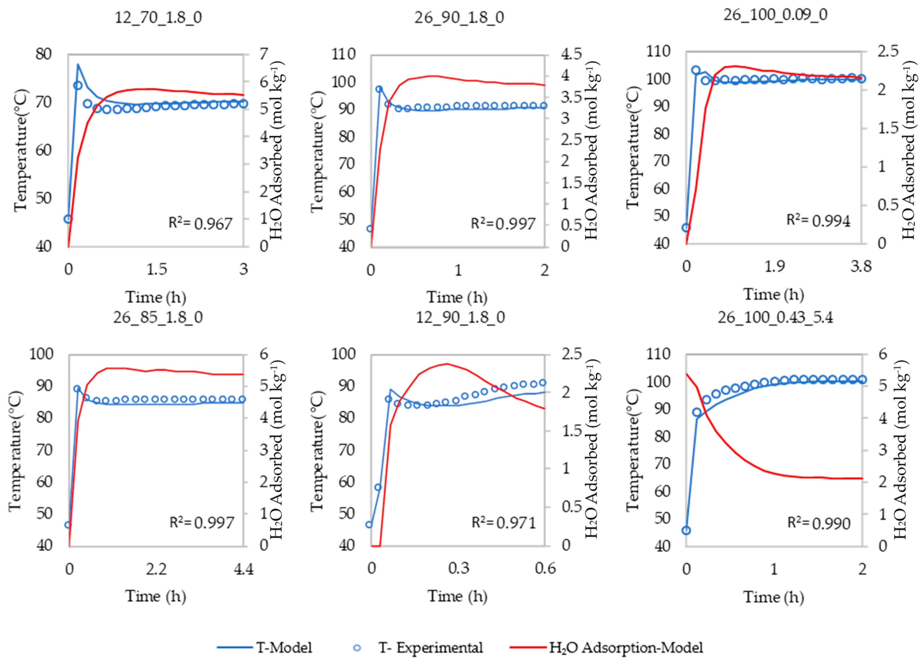
The experimental data and the model predictions for CO2/H2O mass transfer in the adsorption stage are presented in Figure 3. The CO2 mass transfer, equilibrium H2O uptake, H2O mass transfer kinetics and heat transfer in the desorption stage are presented in Figure 4, Figure 5 and Figure 6. The figures show that the experimental data are in close agreement with the model predictions. The results of the parameter estimations are listed in Table 2 along with the constants used.

4. Results of Multi-Objective Optimization

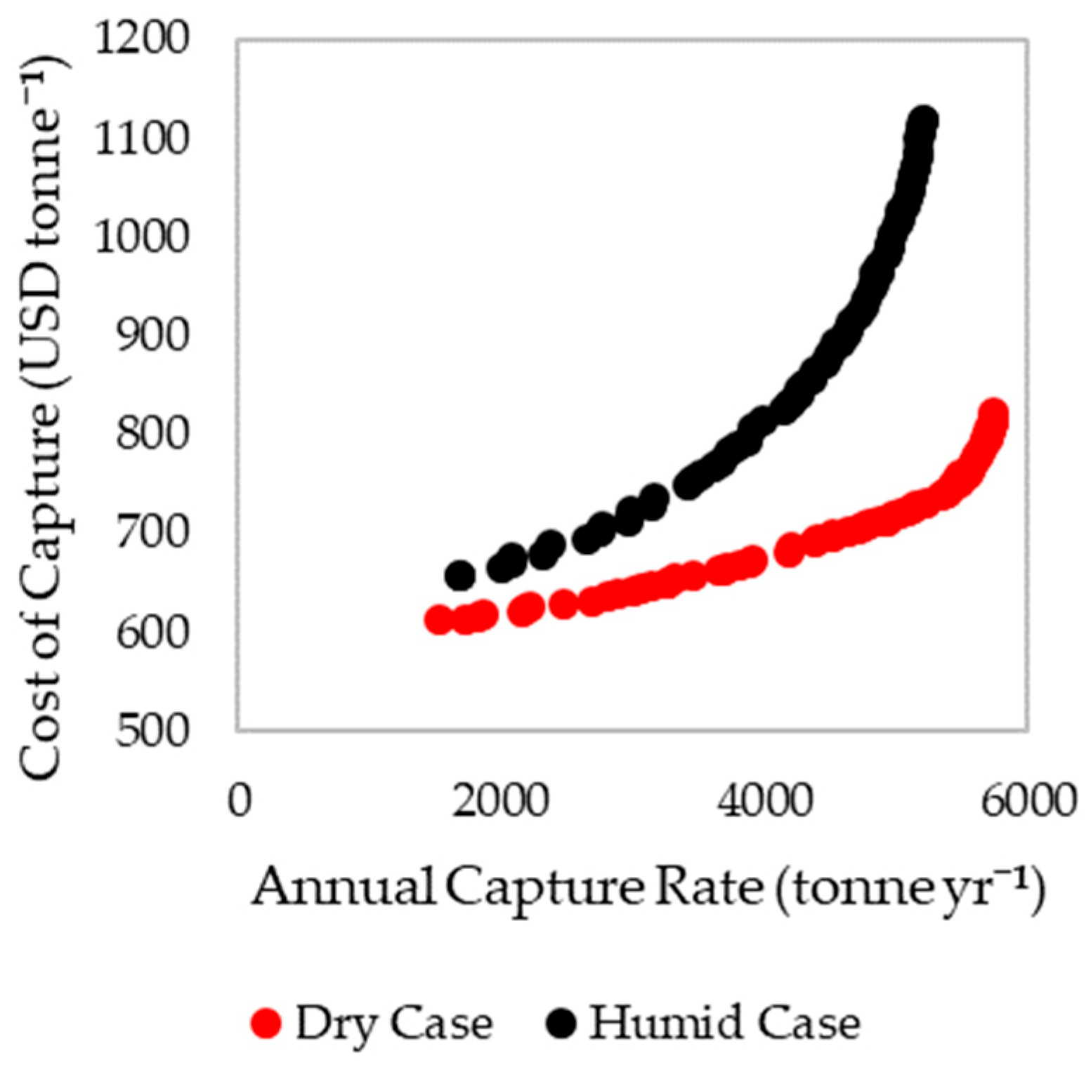
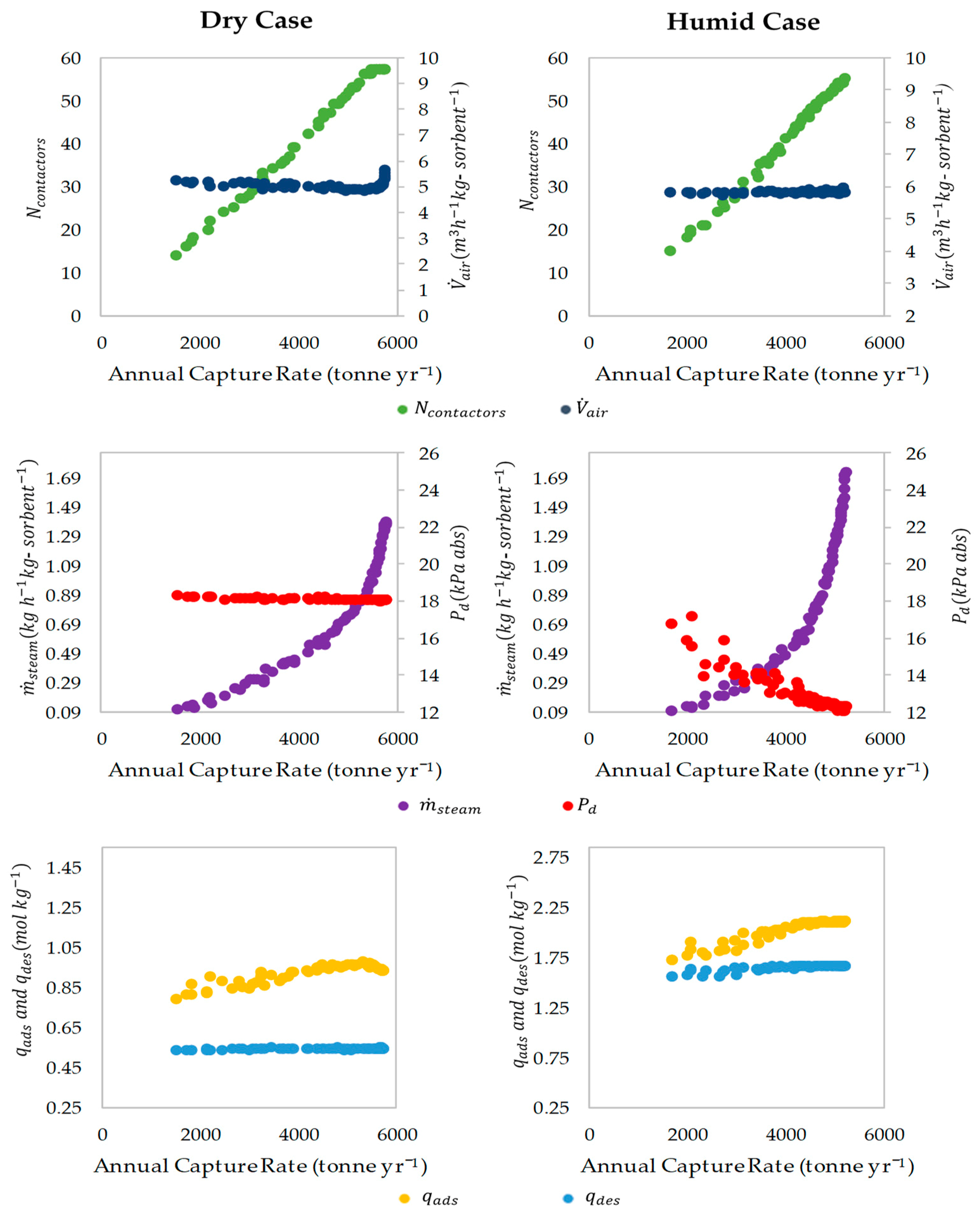
The plots of the Pareto non-dominated fronts from the results of the MOO are presented in Figure 7 and Figure 8 for the dry and the humid cases. From Figure 7, it is apparent that the dry case allows for a lower cost of capture than the humid case for all capture rates. Moreover, it can be seen that the cost of capture increases as the capture rate is increased for both cases. From Figure 8, it is apparent that as the capture rate is increased, N c o n t a c t o r s , m ˙ s t e a m and q a d s are also increased. Additionally, P d is reduced for the humid case. Negligible changes are seen in the other parameters.
The set of variables which yielded the lowest cost scenarios for the humid and the dry cases are listed in Table 3, along with the resulting cycle times and energy requirements of the process.
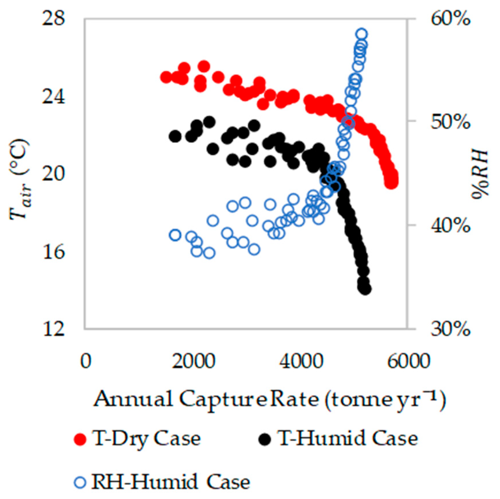
The temperature and RH at which the air could enter the process for each of the points in the Pareto plots, as calculated with Equations (10) and (11), are depicted in Figure 9.
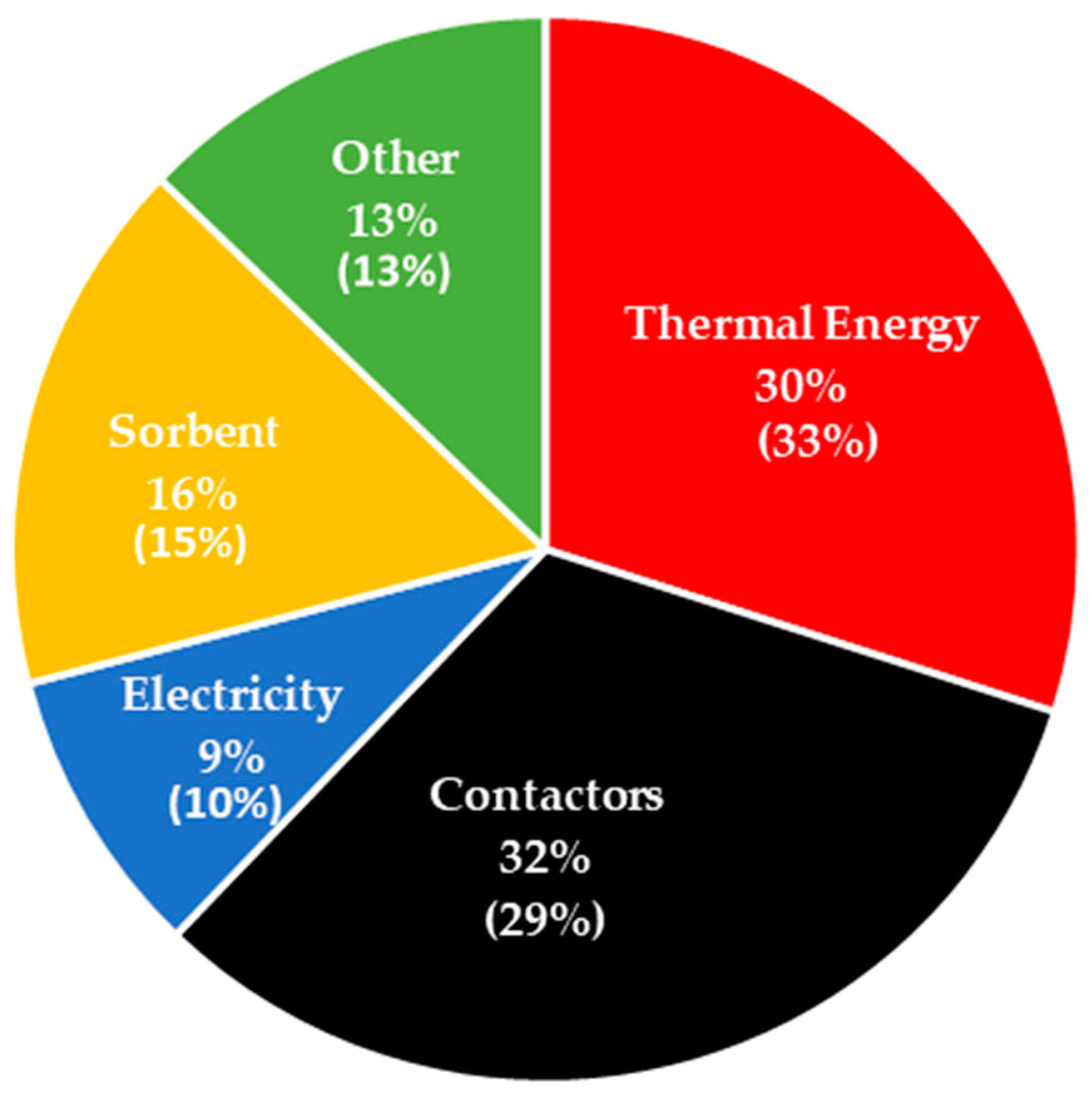
The breakdown of the cost of capture for the preferred conditions is shown in Figure 10. It was observed that both the dry and humid case showed a similar cost breakdown. The biggest contributors were identified as the cost of thermal energy and the contactors.
The results of the sensitivity analysis on the model values is shown in Figure 11. As the two cases had a similar cost breakdown, the sensitivities were almost identical.

5. Discussion

5.1. Influence of Process Conditions

It can be noted that the cost of capturing under humid conditions is higher than that under dry conditions for all the capture rates in the Pareto fronts (Figure 7). The presence of moisture allows the process to take advantage of the improved CO2 adsorption capacities of the sorbent [16] as indicated by the higher q a d s and q d e s in the humid case. However, this also leads to a longer t a d s and t d e s , which increases t c y c l e . This reduces the annual capture rate, and so increases the cost of capture (see Equations (12) and (13)).
In the humid case, the process is restricted from using smaller q a d s and q d e s , due to the large amount of water adsorbed. As the water adsorption/desorption is significantly faster than that of CO2 (see Figure 3), at lower q a d s and q d e s (shorter t a d s and t d e s ) values, there is a much higher proportion of H2O adsorbed in comparison to CO2. This in turn translates to a proportionately higher cost of thermal energy consumed for desorbing the H2O. And as the thermal energy accounts for a large fraction of the cost, this has a significant impact on the economics of the process. These results indicate that using a sorbent with a reduced affinity for water may improve the economics of the process.
When comparing the process conditions which yielded the lowest cost scenario, both the humid and the dry case had a similar adsorption air flow rate ( V ˙ a i r ), desorption temperature ( T d ) and desorption pressure ( P d ). At high V ˙ a i r , the rate at which CO2 can be captured is increased, which can reduce the cycle time. However, this is done at the compromise of higher pressure drops across the contactors resulting in an increased electrical energy consumption.
The preferred Td was identified as 100 °C which is the upper limit used for the optimization. This is due to the faster desorption kinetics presented at higher temperatures [17], which leads to shorter cycle times. The upper limit for this study was set at 100 °C, as solid supported amines have been reported to undergo degradation at high temperatures [32]. However, the sorbent in this study was previously reported [17] to be stable at temperatures up to 100 °C, under the desorption conditions evaluated here. In the case of Pd, the preferred value is a balance between benefitting from the faster desorption rates (shorter cycle times) offered by the lower pressures [17] and the increased expenses for electrical energy.
The identification of the preferred steam flow rate, m ˙ s t e a m , is similar to that of Pd. The preferred value is a balance between benefitting from the faster desorption rates (shorter t d e s ) offered by the faster steam flow rates [17] at the compromise of increased cost of thermal energy. In both cases, the steam flow rate with the lowest cost was the close to its lower bounds, indicating that benefit of shorter t d e s is not justified by the higher energy cost. This can be attributed to the fact that thermal energy demand has the one of the biggest impacts on the economics of the process (see Figure 10).
When comparing the energy requirements, the electrical energy consumption was similar for both cases. However, the humid case needed more thermal energy to heat up the sorbent during the desorption. This is because the energy consumed by the water being desorbed from the sorbent, cools it down [17]. Therefore, more heat needs to be provided in the humid case, to maintain the desired desorption temperature.
From Figure 11, it can be seen that both cases display similar sensitivities to the values studied. The final result was seen to be relatively insensitive to the values studied, as the cost was seen to vary by <±4% for a variation of ±10% in the parameters. The cost of thermal energy and the contactor were identified to be the variables which most affected the cost of capture. This is consistent with the fact that thermal energy and the cost of the contactor are the two largest contributions to the cost (see Figure 10). The discount factor was also seen to have a large impact on the cost of capture and a value of 10% is conservative for the current economic conditions.

5.2. Pareto Non-Dominated Fronts

In both cases, the cost of capture increases as the capture rate increases. As seen in the Pareto plots of the variables (Figure 8), the increase in the capture rate is achieved mainly by using a higher N c o n t a c t o r s which increases the amount of CO2 captured. However, to increase N c o n t a c t o r s , either t a d s needs to be increased or t d e s needs to be decreased to satisfy the inequality constraint in Equation (14). This is fulfilled by increasing m ˙ s t e a m , which shortens t d e s by improving the CO2 desorption kinetics. P d is also decreased for the humid case, which can be attributed to the comparatively longer t d e s , which demands a greater increase in the kinetics to satisfy the inequality constraint in Equation (14). Furthermore, q a d s is increased to increase the t a d s and q d e s is kept relatively constant which shortens t d e s when used in combination with higher m ˙ s t e a m , and lower P d . These changes to the process conditions (except q d e s ) increase the annual capture rate while incurring additional expenses as explained in Section 5.1. The increases in the thermal energy demand and the contactors are particularly significant as they are the two biggest contributors to the economics of the process.
V ˙ a i r , can be seen to be relatively constant for most of the Pareto front. This can be expected since it is selected based on the compromise between the positive effect of a shorter t a d s and the negative of a higher energy requirement for high flow rates. It is likely that the balance between the two does not significantly vary for the different points in the Pareto plot. In the dry case, there is a steep increase in V ˙ at the higher capture rate end which coincides with a steep increase in the cost. This highlights that while slightly higher capture rates can be achieved with higher V ˙ a i r , it is accompanied by a significant increase in the cost.
The results of the sensitivity analysis carried out on the MOO options is included in Section S6 of the Supplementary Information, and it is evident that the Pareto fronts are insensitive to the MOO options used.

5.3. Temperature and RH of the Incoming Air to the Process

For the lowest cost cases, the incoming air temperature, T a i r , was calculated to be 25 °C for the dry case and 22 °C for the humid case (see Figure 9). The RH of the humid case was calculated to be 39%. It is noted that, while the dry case yielded a lower cost, it is unrealistic to expect completely dry conditions anywhere in the world. However, the conditions calculated for the humid case are far more realistic and can be expected of regions with sub-tropical climates.
T a i r can be seen to reduce with increases in the capture rate (see Figure 9). This can be attributed to the higher steam flow rates available at the higher capture rate/higher cost end of the Pareto fronts. It is also apparent that the humid case allows for significantly lower temperatures. This is owing to the water which gets desorbed from the sorbent which condenses, releasing additional thermal energy. These results indicate that the process could operate in colder climates with higher humidity, at the compromise of a higher cost of capture. It is also noteworthy that when operating at a higher moisture level than 1% mol-H2O, lower T a i r may be achieved due to the increased adsorption of water, although this would also likely lead to a higher cost of capture.

5.4. Comparison to Results of Other Studies

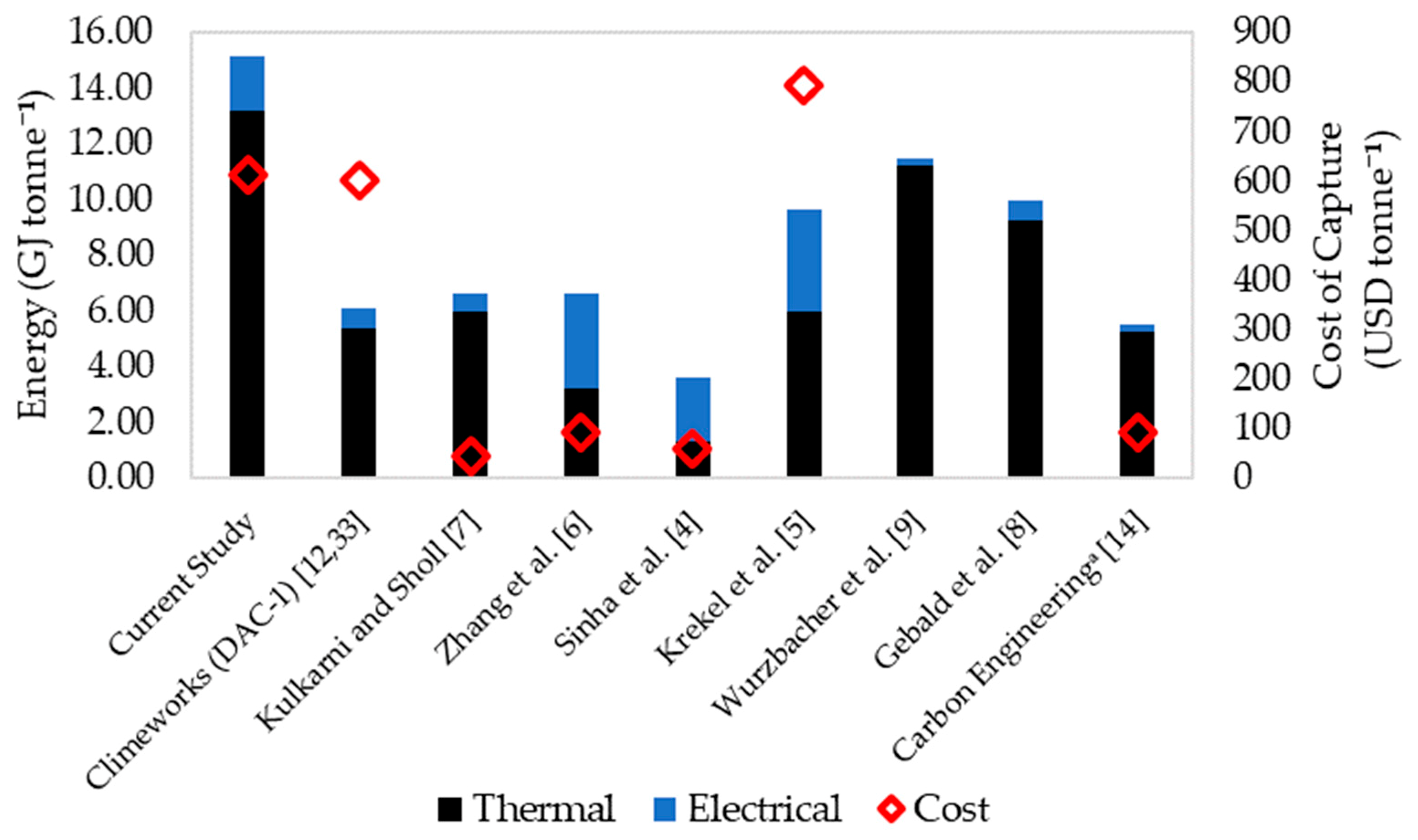
The cost and energy data for the lowest cost case described in the current study is presented alongside data found for other DAC processes [4,5,6,7,8,9,12,14,33] in Figure 12. The data are that of the lowest cost case described in the respective studies.
It is evident that the cost of capture presented in the current study is in the upper end of the range of costs reported for similar processes. However, it can be noted that the cost in the current study is similar to that reported by Climeworks based on the actual performance of their first-generation DAC system (DAC-1) [12]. In comparison, the other values depicted in Figure 12 are subjective to the scope of the respective study and the assumptions that were used. For example, Kulkarni and Sholl [7] and Zhang et al. [6] did not include the capital expenses of the equipment in their studies. Krekel et al. [5] expanded on the work carried out by Zhang et al. [6], and reported that once the capital expenses are included, the cost of capture is increased significantly. Moreover, the costs of capture depicted in Figure 12 for Zhang et al. [6] and Krekel et al. [5] are based on scenarios where the energy is supplied with fossil fuels, as opposed to the low carbon solar energy used here. Krekel et al. [5] reported that the cost of capture increases from 792 to 1333 USD tonne−1 when the emissions from energy generation are considered. They further reported that if wind energy is used, a capture cost of 824 USD tonne−1 can be achieved. Zhang et al. [6] estimated an increase from 91 to 225 USD tonne−1 for a system utilizing wind and nuclear energy.
The large difference between the results of this study and that of the Sinha et al. [4] is in part due to the two main differences. Firstly, the cash flow was not discounted [4]. The second reason is due to the nature of the sorbent used. Sinha et al. [4] evaluated a monolithic sorbent which was assumed to be self-contained. In comparison, the pelletized sorbent in the current study needs to be contained in contactors which contribute to about a third of the total cost. This may indicate the advantage that monolithic sorbents have over pelletized ones. Furthermore, Sinha et al. [4] also did not consider the CO2 emissions from energy generation in their calculations.
Apart from these, another major reason for the higher cost reported in the current study is the slower kinetics of the sorbent evaluated. It was previously reported [16] that the large loading of PEI in this sorbent resulted in a large CO2 uptake capacity although at the sacrifice of significant mass transfer limitations, which resulted in a slow uptake rate of CO2. The effect of this is evident here, where long cycle times are required for the process (7.51 h for the dry case). In comparison, for other studies, the reported cycle times are in the range of 1.27 [4] to 4 h [7]. These long cycle times result in a lower annual capture rate and hence a larger cost. Furthermore, it should be noted that the subject sorbent was shown to provide better adsorption performance at the higher temperature of 46 °C [16]; thus, it may be that further improvements in the process economics could be achieved by tailoring the design of sorbent material so that its optimum sorption performance occurs at the intended adsorption temperature.
The slow kinetics also have a large effect on the energy requirement of the process. As seen in Table 3, the thermal energy requirement is dominated by the energy for steam generation, and for longer desorption times, larger amounts of steam are needed to desorb the CO2. This would explain the larger thermal energy requirement of the process in comparison to the other studies depicted in Figure 12. However, the electrical energy requirement of the process is in close agreement with most of the values reported in literature. While Wurzbacher et al. [9] and Gebald et al. [8] reported much lower values, they only evaluated the desorption stage and did not include the energy needed to pump the air through contactors during adsorption.
It is difficult to make direct comparisons with the costs reported by Carbon Engineering [14], as this corresponds to a completely different type of process. However, it is noted that the need for very high temperatures (900 °C) for the regeneration of the sorbent, may make the process more reliant on fossil fuel-based energy. In comparison, the processes using SSA could more easily be powered with relatively inexpensive low carbon energy sources like solar thermal hot water systems.

5.5. Case Studies

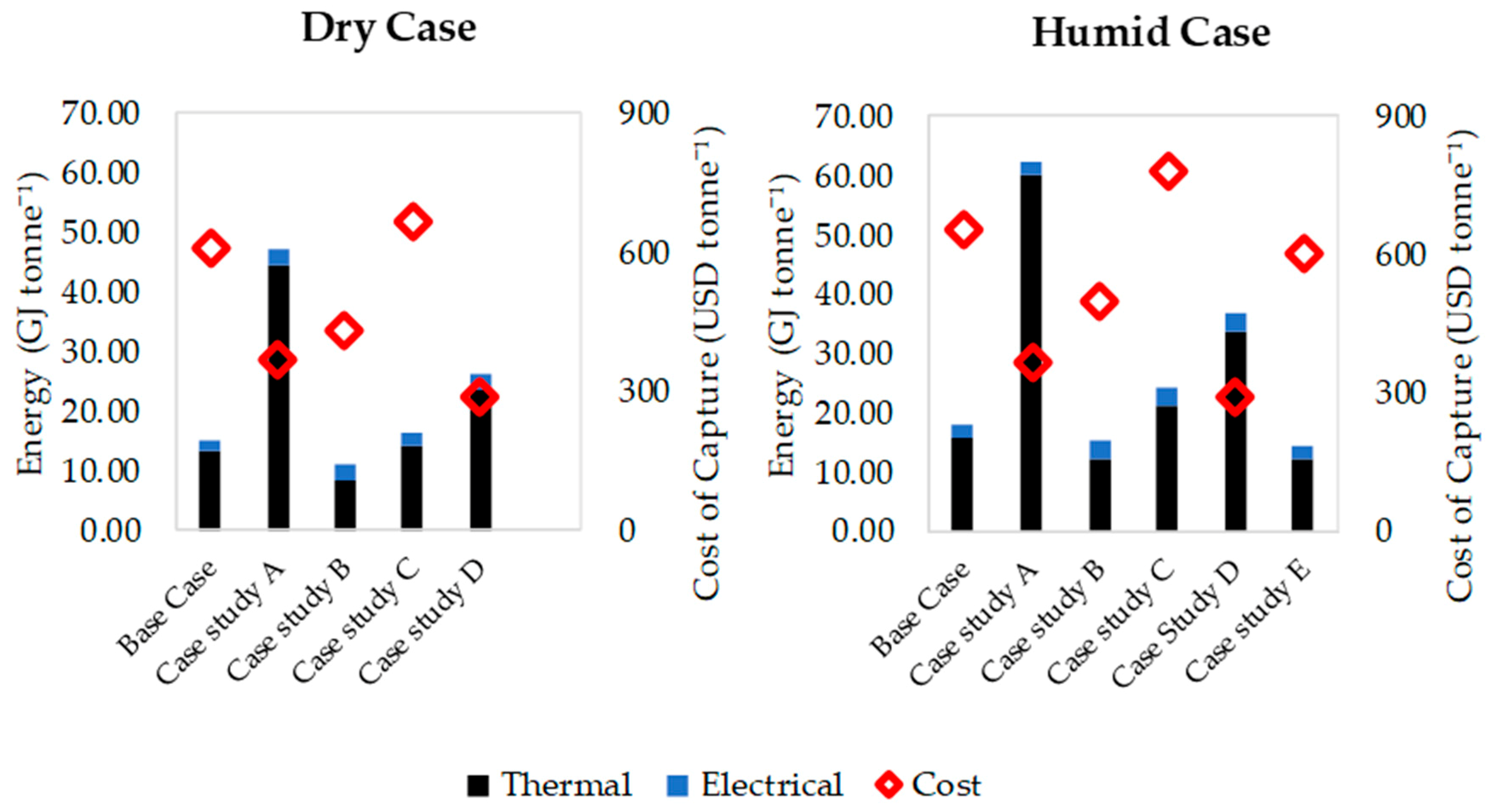
In this section, the effect of five different scenarios on the cost of capture is evaluated. The scenarios were selected based on the main cost drivers and the limitations of the process identified in the previous sections. For these evaluations, the MOO was repeated with the respective changes described below for each scenario.
Case study A: Thermal energy from waste heat utilization—This scenario was chosen because the main contributor to the cost of the capture was identified to be the thermal energy requirement. Moreover, the low temperatures (≤100 °C) used for the desorption process makes it possible for integration with waste heat sources. It was assumed that this energy could be achieved free of charge.
Case study B: Hypothetical sorbent with faster kinetics—This scenario addresses the limitation of slow mass transfer kinetics of the sorbent (longer cycle times). Here a hypothetical sorbent, with improved mass transfer kinetics of CO2 is used. Potential means of achieving this include using additives which improve CO2 diffusion in the amine phase [34,35,36,37] and using support materials with high surface areas [38] and/or large pore sizes [39] to better disperse the amines and thus improve their accessibility to the CO2. To carry out the evaluation, k C O 2 , a d s in Equation (1) and k 1 in Equation (3) were multiplied by a factor of 2, to emulate a sorbent with twice as faster CO2 mass transfer kinetics.
Case study C: Hypothetical sorbent with faster kinetics but lower CO2 uptake capacity—This scenario considers an iteration of case study B. It is possible that the improvements made to the kinetics would come at the expense of a smaller CO2 uptake capacity. For example, it has been reported in literature that lower PEI loadings (% wt) on the sorbent results in lower uptake capacities and faster kinetics [40,41]. For this scenario, a hypothetical sorbent where the kinetics are increased by a factor of 2, at the compromise of a halved equilibrium capacity, is evaluated. To carry out the evaluation, k C O 2 , a d s in Equation (1) and k 1 in Equation (3) were multiplied by a factor of 2, and q e q , C O 2 , a d s in Equation (1) was multiplied by 0.5.
Case study D: Combination of case studies A and B, where a sorbent with superior kinetics is used with waste heat utilization.
Case study E: Hypothetical sorbent with lower H2O uptake capacity—As mentioned earlier, while adsorbing from humid air enhances the CO2 uptake, a proportionately higher amount of water is also adsorbed. This results in a higher energy requirement for desorption of water. It has been reported [42] that the water uptake by PEI-silica sorbents could be reduced by using hydrophobic silica as the support material. The study [42] further demonstrated that the benefit of enhanced CO2 capacities when adsorbing in the presence of moisture could be retained, in spite of the reduction of the water uptake. Modifications to the amine such as reducing the proportion of primary amines [43] and introduction of methyl groups [44] have also been reported to reduce the water uptake by these sorbents. For this scenario, a hypothetical sorbent, with half the water uptake capacity is evaluated. To carry out the evaluation, q e q , H 2 O , a d s in Equation (1) and K 0 in Equation (5) were multiplied by a factor of 0.5.
For case studies B–E, the current study does not attempt to identify exactly how the sorbent may be developed to meet the specified criteria but simply aims to estimate the impact each modification would have on the economics of the process. The results of this exercise are meant to be taken as a guide, for identifying the direction future research into sorbent development may head towards.
The results of the case studies are depicted in Figure 13. From the results, it is evident that using waste heat to provide the thermal energy yields the biggest reduction (~ 42%) in the cost of capture. This reduction is an effect of two things. Firstly, the large contribution of the thermal energy to the cost is eliminated. Secondly, the process takes advantage of the free thermal energy and utilizes higher m ˙ s t e a m to increase the capture rate. This is evident in the thermal energy demands which are more than 3-fold higher than that of the base case. The higher m ˙ s t e a m facilitates faster desorption which reduces t c y c l e , which in turn lowers the cost of capture. While the reductions are attractive, it should also be noted that the utilization of waste heat would restrict the locations where DAC systems could be operated to areas such as industrial parks. DAC systems with waste heat utilization would also likely be more practical for carbon capture and utilization projects rather than carbon capture and sequestration projects. This is because sequestration sites would likely be located far away from industrial sites, which would require the transportation of CO2, incurring additional costs. In comparison, the utilization could be done at the same site the capture is done.
When comparing cases B to E, it can be seen that developing sorbents with improved CO2 mass transfer kinetics would have the biggest impact on reducing the cost (~27% reduction). With faster kinetics, shorter t c y c l e could be achieved, which reduces the cost of capture. The thermal energy demand can also be seen to reduce as hypothesized. However, case study C shows that the improvements to the kinetics of the sorbent should not be made at the expense of the CO2 uptake capacity. Case study D shows that combining faster sorbents with waste heat utilization could lower the cost of capture by ~54%. Finally, case study E shows that an 8% reduction in cost can be achieved by using less hygroscopic sorbents, which can be attributed to the reduced thermal energy requirement. Although the costs for these case studies are still quite high, these give an indication of the relative impact each modification could have on the economics of the process.

6. Conclusions

A process model was proposed, for a DAC process employing a S-TVSA cycle, and validated with laboratory experimental results. To evaluate the technoeconomic performance of the process, the model was subjected to a MOO with the objectives of minimizing the cost of capture and maximizing the amount of CO2 captured. A minimum cost of capture of 612 USD tonne−1 was calculated for a process with air entering at 25 °C under dry conditions, and a cost of 657 USD tonne−1 was calculated for air entering at 22 °C and 39% RH. The humid case yielded higher costs than the dry case, as an effect of the additional energy required to desorb the water that gets co-adsorbed on the sorbent. While the dry case yielded the lower cost, it is noted that the humid case is more realistic for practical DAC systems, and that the inlet air conditions correspond to that typical of subtropical climates. It was observed that the capture rate of the process could be increased (at the expense of a higher cost of capture) by increasing the number of contactors, using more aggressive desorption conditions and changing the cycle times. The process variables which had the most effect on the results were identified as the steam flow rate and the number of contactors. The relatively higher costs calculated here, in comparison to the results of prior studies, were identified to be a result of the differences in the assumptions and scope of the respective studies, and the slower kinetics of the sorbent evaluated in the current study. It was identified that using a sorbent with two-fold faster kinetics could reduce the cost by ~27% and that the utilization of waste heat could produce a ~42% reduction in cost. A combination of both would allow the cost to be reduced by ~54%.
In summary, the process evaluated in this study does not appear to be economically feasible in the current state. However, the study identified several avenues which could lead to improvements. Of these, the improvements in sorbent design suggested here could realistically be achieved even with the current state of the technology. However, further research is needed for areas such as the development of low-cost contactors. If a combination of these improvements is achieved, this DAC process has the potential to be economically feasible and a valuable tool for combatting climate change in the future.
Supplementary Materials

The following are available online at https://www.mdpi.com/2227-9717/7/8/503/s1, Section S1: Calculations for the unit operations, Section S2: Calculation of energy consumption, Section S3: Capital cost estimation, Section S4: Estimation of cost of sorbent, Section S5: NPV analysis, S6: Desorption Stage: Model Validation contd., S7: Sensitivity of the results to the MOO options.

Author Contributions

Conceptualization, R.P.W., G.P.K., H.Y., A.F.A.H. and A.L.C.; methodology, R.P.W., G.P.K., H.Y., A.F.A.H. and A.L.C.; software, R.P.W.; validation, R.P.W., G.P.K., H.Y., A.F.A.H. and A.L.C.; investigation, R.P.W.; resources, G.P.K., H.Y., A.F.A.H. and A.L.C.; writing—original draft preparation, R.P.W.; writing—review and editing, R.P.W., G.P.K., H.Y., A.F.A.H. and A.L.C.; visualization, R.P.W.; supervision, G.P.K., H.Y., A.F.A.H. and A.L.C.; project administration, A.F.A.H. and A.L.C.; funding acquisition, A.F.A.H. and A.L.C.

Funding

This research received no external funding.

Acknowledgments

The authors acknowledge Antonio Benci and David Zuidema, Monash Instrumentation Facility, for assistance in designing and programming some of the componentry in the experimental set up.

Conflicts of Interest

The authors declare no conflict of interest.

References

  1. IPCC. IPCC Special Report on Carbon Dioxide Capture and Storage; Prepared by Working Group III of the Intergovernmental Panel on Climate Change; Cambridge University Press: Cambridge, UK; New York, NY, USA, 2005. [Google Scholar]
  2. Koytsoumpa, E.I.; Bergins, C.; Kakaras, E. The CO2 economy: Review of CO2 capture and reuse technologies. J. Supercrit. Fluids 2018, 132, 3–16. [Google Scholar] [CrossRef]
  3. Sanz-Pérez, E.S.; Murdock, C.R.; Didas, S.A.; Jones, C.W. Direct Capture of CO2 from Ambient Air. Chem. Rev. 2016, 116, 11840–11876. [Google Scholar] [CrossRef] [PubMed]
  4. Sinha, A.; Darunte, L.A.; Jones, C.W.; Realff, M.J.; Kawajiri, Y. Systems Design and Economic Analysis of Direct Air Capture of CO2 through Temperature Vacuum Swing Adsorption Using MIL-101(Cr)-PEI-800 and mmen-Mg2(dobpdc) MOF Adsorbents. Ind. Eng. Chem. Res. 2017, 56, 750–764. [Google Scholar] [CrossRef]
  5. Krekel, D.; Samsun, R.C.; Peters, R.; Stolten, D. The separation of CO2 from ambient air—A techno-economic assessment. Appl. Energy 2018, 218, 361–381. [Google Scholar] [CrossRef]
  6. Zhang, W.; Liu, H.; Sun, C.; Drage, T.C.; Snape, C.E. Capturing CO2 from ambient air using a polyethyleneimine–silica adsorbent in fluidized beds. Chem. Eng. Sci. 2014, 116, 306–316. [Google Scholar] [CrossRef]
  7. Kulkarni, A.R.; Sholl, D.S. Analysis of Equilibrium-Based TSA Processes for Direct Capture of CO2 from Air. Ind. Eng. Chem. Res. 2012, 51, 8631–8645. [Google Scholar] [CrossRef]
  8. Gebald, C.; Repond, N.; Wurzbacher, J.A. Steam Assisted Vacuum Desorption Process for Carbon Dioxide Capture. U.S. Patent No. US20170203249A1, 20 July 2017. [Google Scholar]
  9. Wurzbacher, J.A.; Gebald, C.; Piatkowski, N.; Steinfeld, A. Concurrent Separation of CO2 and H2O from Air by a Temperature-Vacuum Swing Adsorption/Desorption Cycle. Environ. Sci. Technol. 2012, 46, 9191–9198. [Google Scholar] [CrossRef]
  10. Climeworks. Our Technology. Available online: https://www.climeworks.com/our-technology/ (accessed on 14 June 2019).
  11. Gobal Thermostat. A Unique Capture Process. Available online: https://globalthermostat.com/a-unique-capture-process/ (accessed on 14 June 2019).
  12. Kramer, D. Can carbon capture from air shift the climate change equation? Phys. Today 2018, 71, 26–29. [Google Scholar] [CrossRef] [Green Version]
  13. Carbon Engineering. Carbon Engineering: CO2 Capture and the Synthesis of Clean Transportation Fuels. Available online: https://carbonengineering.com/ (accessed on 16 July 2019).
  14. Keith, D.W.; Holmes, G.; St. Angelo, D.; Heidel, K. A Process for Capturing CO2 from the Atmosphere. Joule 2018, 2, 1573–1594. [Google Scholar] [CrossRef]
  15. Jackson, R.B.; Baker, J.S. Opportunities and Constraints for Forest Climate Mitigation. Bioscience 2010, 60, 698–707. [Google Scholar] [CrossRef] [Green Version]
  16. Wijesiri, R.P.; Knowles, G.P.; Yeasmin, H.; Hoadley, A.F.A.; Chaffee, A.L. CO2 Capture from Air Using Pelletised Polyethyleneimine Impregnated MCF Silica. Ind. Eng. Chem. Res. 2019, 58, 3293–3303. [Google Scholar] [CrossRef]
  17. Wijesiri, R.P.; Knowles, G.P.; Yeasmin, H.; Hoadley, A.F.A.; Chaffee, A.L. Desorption Process for Capturing CO2 from Air with Supported Amine Sorbent. Ind. Eng. Chem. Res. 2019. [Google Scholar] [CrossRef]
  18. Glueckauf, E.; Coates, J.I. 241. Theory of chromatography. Part IV. The influence of incomplete equilibrium on the front boundary of chromatograms and on the effectiveness of separation. J. Chem. Soc. 1947, 315–1321. [Google Scholar] [CrossRef]
  19. Sircar, S.; Hufton, J.R. Why Does the Linear Driving Force Model for Adsorption Kinetics Work? Adsorption 2000, 6, 137–147. [Google Scholar] [CrossRef]
  20. Do, D.D. Adsorption Analysis: Equilibria and Kinetics; Imperial College Press: London, UK, 1998. [Google Scholar]
  21. Knowles, G.P.; Chaffee, A.L. Shaped Silica-polyethyleneimine Composite Sorbents for CO2 Capture via Adsorption. Energy Procedia 2017, 114, 2219–2227. [Google Scholar] [CrossRef]
  22. Gebald, C.; Piatkowski, N.; Rüesch, T.; Wurzbacher, J.A. Low-Pressure Drop Structure of Particle Adsorbent Bed for Adsorption Gas Separation Process. Patent No. WO2014170184A1, 23 October 2014. [Google Scholar]
  23. Couper, J.R. Chemical Process Equipment: Selection and Design, 2nd ed.; Elsevier/Butterworth-Heinemann: Amsterdam, The Netherlands, 2010. [Google Scholar]
  24. Antoine, L.C. Tensions des vapeurs; nouvelle relation entre les tensions et les températures Comptes Rendus. Comptes Rendus des Séances de l’Acad. des Sci. 1888, 107, 681–836. [Google Scholar]
  25. Seider, W.D. Product and Process Design Principles: Synthesis, Analysis, and Evaluation, 3rd ed.; John Wiley: Hoboken, NJ, USA, 2009. [Google Scholar]
  26. Sinnott, R.K. Coulson & Richardson’s chemical engineering. In Chemical Engineering Design, 4th ed.; Elsevier Butterworth-Heinemann: Oxford, UK, 2005; Volume 6. [Google Scholar]
  27. Brennan, D. Process Industry Economics: An International Perspective; IChemE: Rugby, UK, 1998. [Google Scholar]
  28. IEA Solar Heating & Cooling Programme. Solar Heat Worldwide 2018; International Energy Agency: Paris, France, 2018. [Google Scholar]
  29. IRENA. Renewable Power Generation Costs in 2017; International Renewable Energy Agency: Abu-Dhabi, UAE, 2018. [Google Scholar]
  30. South East Water Corporation. 2018-19 Pricing Handbook; South East Water Corporation: Melbourne, Australia, 2018. [Google Scholar]
  31. Deb, K. Multi-Objective Optimization Using Evolutionary Algorithms, 1st ed.; John Wiley & Sons: New York, NY, USA, 2001. [Google Scholar]
  32. Jahandar Lashaki, M.; Khiavi, S.; Sayari, A. Stability of amine-functionalized CO2 adsorbents: A multifaceted puzzle. Chem. Soc. Rev. 2019, 48, 3320–3405. [Google Scholar] [CrossRef]
  33. Bajamundi, C.J.E.; Koponen, J.; Ruuskanen, V.; Elfving, J.; Kosonen, A.; Kauppinen, J.; Ahola, J. Capturing CO2 from air: Technical performance and process control improvement. J. CO2 Util. 2019, 30, 232–239. [Google Scholar] [CrossRef]
  34. Wang, J.; Huang, H.; Wang, M.; Yao, L.; Qiao, W.; Long, D.; Ling, L. Direct Capture of Low-Concentration CO2 on Mesoporous Carbon-Supported Solid Amine Adsorbents at Ambient Temperature. Ind. Eng. Chem. Res. 2015, 54, 5319–5327. [Google Scholar] [CrossRef]
  35. Goeppert, A.; Meth, S.; Prakash, G.K.S.; Olah, G.A. Nanostructured silica as a support for regenerable high-capacity organoamine-based CO2 sorbents. Energy Environ. Sci. 2010, 3, 1949–1960. [Google Scholar] [CrossRef]
  36. Sakwa-Novak, M.A.; Tan, S.; Jones, C.W. Role of Additives in Composite PEI/Oxide CO2 Adsorbents: Enhancement in the Amine Efficiency of Supported PEI by PEG in CO2 Capture from Simulated Ambient Air. ACS Appl. Mater. Interfaces 2015, 7, 24748–24759. [Google Scholar] [CrossRef]
  37. Choi, S.; Gray, M.L.; Jones, C.W. Amine-Tethered Solid Adsorbents Coupling High Adsorption Capacity and Regenerability for CO2 Capture from Ambient Air. ChemSusChem 2011, 4, 628–635. [Google Scholar] [CrossRef]
  38. Lu, W.; Sculley, J.P.; Yuan, D.; Krishna, R.; Zhou, H.C. Carbon Dioxide Capture from Air Using Amine-Grafted Porous Polymer Networks. J. Phys. Chem. C 2013, 117, 4057–4061. [Google Scholar] [CrossRef]
  39. Chen, Z.; Deng, S.; Wei, H.; Wang, B.; Huang, J.; Yu, G. Polyethylenimine-Impregnated Resin for High CO2 Adsorption: An Efficient Adsorbent for CO2 Capture from Simulated Flue Gas and Ambient Air. ACS Appl. Mater. Interfaces 2013, 5, 6937–6945. [Google Scholar] [CrossRef]
  40. Darunte, L.A.; Oetomo, A.D.; Walton, K.S.; Sholl, D.S.; Jones, C.W. Direct Air Capture of CO2 Using Amine Functionalized MIL-101(Cr). ACS Sustain. Chem. Eng. 2016, 4, 5761–5768. [Google Scholar] [CrossRef]
  41. Goeppert, A.; Zhang, H.; Czaun, M.; May, R.B.; Prakash, G.K.S.; Olah, G.A.; Narayanan, S.R. Easily Regenerable Solid Adsorbents Based on Polyamines for Carbon Dioxide Capture from the Air. ChemSusChem 2014, 7, 1386–1397. [Google Scholar] [CrossRef]
  42. Zhang, H.; Goeppert, A.; Olah, G.A.; Prakash, G.K.S. Remarkable effect of moisture on the CO2 adsorption of nano-silica supported linear and branched polyethylenimine. J. CO2 Util. 2017, 19, 91–99. [Google Scholar] [CrossRef]
  43. Didas, S.A.; Kulkarni, A.R.; Sholl, D.S.; Jones, C.W. Role of Amine Structure on Carbon Dioxide Adsorption from Ultradilute Gas Streams such as Ambient Air. ChemSusChem 2012, 5, 2058–2064. [Google Scholar] [CrossRef]
  44. Sehaqui, H.; Gálvez, M.E.; Becatinni, V.; cheng Ng, Y.; Steinfeld, A.; Zimmermann, T.; Tingaut, P. Fast and Reversible Direct CO2 Capture from Air onto All-Polymer Nanofibrillated Cellulose—Polyethylenimine Foams. Environ. Sci. Technol. 2015, 49, 3167–3174. [Google Scholar] [CrossRef]
Figure 1. (a) A schematic of the proposed air-sorbent contactor configuration and (b) the process flow diagram of the proposed Direct Air Contact (DAC) system.
Processes 07 00503 g001
Figure 2. (a) The adsorption/desorption cycle the contactors are subjected to. (b) The operational sequence of the contactors, with one bed in desorption at all times and the rest in adsorption. S1 to S3 refer to the stages in the adsorption/desorption cycle (adsorption, desorption and cooling).
Processes 07 00503 g002
Figure 3. The experimental data and the model predictions for CO2 and H2O adsorption from 420 ppm CO2 in N2 in the dry and humid cases.
Processes 07 00503 g003
Figure 4. The experimental data and the model predictions for CO2 mass transfer kinetics in the desorption stage. Legend for titles AA_BBB_CCC_DD (AA- desorption pressure (kPa abs), BBB-desorption temperature (°C), CCC- desorption steam flow rate (kg h−1 kg-sorbent−1), DD- amount of water adsorbed during adsorption stage (mol kg−1)). More results are depicted in Figure S1 in the Supplementary Information.
Processes 07 00503 g004
Figure 5. The experimental data and the model predictions for equilibrium H2O adsorption amount in the desorption stage at desorption pressures of 12 kPa and 26 kPa abs.
Processes 07 00503 g005
Figure 6. The experimental data and the model predictions for heat transfer and H2O mass transfer kinetics in the desorption stage. Legend for titles AA_BBB_CCC_DD (AA- desorption pressure (kPa abs), BBB-desorption temperature (°C), CCC- desorption steam flow rate (kg h−1 kg-sorbent−1), DD- amount of water adsorbed during adsorption stage (mol kg−1)). More results are depicted in Figure S2 in the Supplementary Information.
Processes 07 00503 g006
Figure 7. Pareto plots for the objective functions of the Multi-Objective Optimization (MOO) for the dry and the humid cases.
Processes 07 00503 g007
Figure 8. Pareto plots for the variables plotted against the capture rate, for the humid and the dry case. The limits for the y-axes are the bounds for each parameter used in the MOO. T d was not plotted as it was constant at 100 °C across all the data points.
Processes 07 00503 g008
Figure 9. The temperature and RH of the inlet air to the process for each of the points in the Pareto plots.
Processes 07 00503 g009
Figure 10. The contributions of various components to the cost of capture for the lowest cost case for the dry and humid case. The value for the humid case is given inside brackets in the data labels.
Processes 07 00503 g010
Figure 11. Tornado plot of the sensitivity of the cost of capture of the lowest cost scenarios for ± 10% changes in the model values.
Processes 07 00503 g011
Figure 12. Comparison of the cost and energy data from this study to that of previous studies. The data are that of the lowest cost case described in the respective studies. a Carbon Engineering refers to an aqueous hydroxide-based process for DAC.
Processes 07 00503 g012
Figure 13. Results of the case studies for the dry and the humid case.
Processes 07 00503 g013
Table 1. Definition of multi-objective optimization problem.
Objectives
Min ( C C O 2 ) and Max ( C R )
Variables
VariableRange
Adsorption air flow rate to a single contactor (m3 h−1 kg-sorbent−1) V ˙ a i r 2 to 10
Total number of contactors N c o n t a c t o r s 2 to 60
Desorption temperature (°C) T d 80 to 100
Desorption pressure (kPa abs) P d 12 to 26
Desorption steam flow rate (kg h−1 kg-sorbent−1) m ˙ s t e a m 0.09 to 1.86
Extent of adsorption (mol kg−1) q a d s 0.25 to 1.50 (dry case)
0.25 to 2.75 (humid case)
Extent of desorption (mol kg−1) q d e s 0.20 to 1.45 (dry case) 0.20 to 2.70 (humid case)
Table 2. The results of the parameter estimation for the adsorption/desorption model and the constants used.
ParameterValue
Adsorption stage mass transfer
Dry case
k C O 2 , a d s   (s−1)2.21 × 10⁻⁵
q e q , C O 2 , a d s (mol kg−1)1.55 × 100
Humid case
k C O 2 , a d s   (s−1)1.31 × 10⁻⁵
q e q , C O 2 , a d s (mol kg−1)2.80 × 100
k H 2 O , a d s (s−1)6.74 × 10⁻⁵
q e q , H 2 O , a d s (mol kg−1)8.30 × 100
Desorption stage mass transfer
CO2 mass transfer kinetics
E a , C O 2   (J mol−1)1.44 × 10⁵
k 1 (s−1)1.06 × 100
k 2 1.03 × 100
k 3 (kg-steam h−1 kg-sorbent−1)7.56 × 10⁻¹
k 4 (kPa−1)−2.29 × 10¹³
k 5 6.66 × 10¹⁴
Freundlich isobar for H2O
K 0 (mol kg−1 kPa−1/n0)1.30 × 107
α 1.51 × 101
A 0 (j mol−1)1.63 × 10³
H2O mass transfer kinetics
E a , H 2 O (J mol−1)4.05 × 10³
k 0 , H 2 O   (s−1)1.90 × 10³
Desorption stage heat transfer
U l a b (W m−2 °C−1)1.70 × 101
Lab scale sorbent bed dimensions
A l a b (m2)3.14 × 10⁻³
m s o r b e n t , l a b (kg)3.45 × 10⁻³
Thermodynamic properties and constants
C p , s o r b e n t (J kg1 °C−1)2.00 × 10³
C p , C O 2 (J kg1 °C−1)9.00 × 10²
C p , s t e a m (J kg1 °C−1)2.00 × 10³
C p , a i r (J kg1 °C−1)1.00 × 10³
H a d s , H 2 O (J kg−1)2.61 × 10⁶
H a d s , C O 2 (J kg−1)2.27 × 10⁶
Table 3. The process conditions which yield the lowest cost scenarios and the resulting cycle times and energy requirements of the process.
Parameter DryHumid
Variables
Adsorption air flow rate to a single contactor (m3 h−1 kg-sorbent−1) V ˙ a i r 5.235.81
Total no of contactors N c o n t a c t o r s 1415
Desorption temperature (°C) T d 100100
Desorption pressure (kPa abs) P d 18.3316.85
Desorption steam flow rate (kg h−1 kg-sorbent−1) m ˙ s t e a m 0.110.11
Extent of adsorption (mol kg−1) q a d s 0.791.72
Extent of desorption (mol kg−1) q d e s 0.541.55
Cycle times
Adsorption (h) t a d s 6.8719.53
Desorption (h) t d e s 0.521.39
Cooling(h) t c o o l 0.110.11
Full cycle (h) t c y c l e 7.5121.03
Energy requirement
Electrical energy for fan (GJ tonne−1) E f a n 1.351.71
Electrical energy for vacuum pump (GJ tonne−1) E v a c u u m 0.610.65
Thermal energy for steam (GJ tonne−1) E s t e a m 7.056.26
Thermal energy to heat sorbent (GJ tonne−1) E b e d 6.149.45
Total electrical (GJ tonne−1) E e l e c t r i c a l 1.962.36
Total thermal (GJ tonne−1) E t h e r m a l 13.1815.71
Total (GJ tonne−1) E t o t a l 15.1418.08
Cost and capture rate
Cost of capture (USD tonne−1) C C O 2 612657
Annual capture rate (tonne yr−1) C R 15211682