1. Introduction
In recent years, there has been an increasing interest in process intensification [
1,
2,
3], which aims to replace traditional batch chemical processes with novel ones combining two or more traditional operations in one hybrid unit. The technological limitations of discontinuous reactors, which may result in safety and productivity constraints, mainly come from their poor heat exchanging performances. These disadvantages excited research teams to design and develop new devices based on the coupling of high heat transfer behavior and good mixing performances [
4,
5]. As a consequence, intensified heat-exchanger/reactors (HEX reactors), which are well-known for their thermal and hydrodynamic performances [
6], have been widely studied for highly exothermic reactions [
7].
By combining a heat-exchanger and a plug-flow reactor in only one unit, the HEX reactor not only meets the demand of miniaturization and low cost of the chemical plant, but also improves the heat and mass transfer ability. Recent works in the field of dynamic characterization and optimization [
6,
7,
8,
9,
10], predictive control [
11,
12,
13], and fault diagnosis and isolation (FDI) [
14,
15,
16,
17,
18,
19,
20] have illustrated that it is important to utilize adequate and computationally efficient dynamic HEX reactor models.
In the application of FDI, many authors have confined their works to a simplified model in which the chemical reaction is not included (see References [
15,
16,
19,
20,
21,
22]). However, there are many parameters which should be taken into consideration when a chemical reaction is introduced. It is essential to completely understand the dynamic characteristics of a new piece of equipment in terms of process safety [
8,
22] and further control. Like most cases, a cell-based model was used in this paper, i.e., each cell is modeled by means of energy and mass balances [
23,
24,
25,
26,
27]. The aim of this paper was to implement the concept of general modeling and validate it on a particular intensified HEX reactor which has already been studied at LGC (Laboratoire de Génie Chimique) [
9]. During modeling, the thermal and hydrodynamic performances of the pilot under the condition of a chemical reaction which brings highly non-linear features were investigated. Once the detailed model is set up and validated, further research, for example on optimal control, adaptive control, fault diagnosis, and fault tolerant control could be carried out on it.
The first part of this paper gives a brief description of the specific intensified HEX reactor. After that, mathematical equations, as well as model structure, are presented according to different parts of the pilot. In addition, parameters which were used to identify the heat transfer coefficient are identified using a genetic algorithm with some of the experimental data. Simulations were carried out in order to investigate the performance of the model. Considering the different aspects involved in the model (hydrodynamic, heat transfer, and reaction), the validation study was conducted in two parts: experiments with water and experiments with the highly exothermic reaction of sodium thiosulfate oxidation. Finally, the results of simulations and real experiments are compared in order to demonstrate the relevance and precision of the developed model.
2. Physical Structure of the Reactor
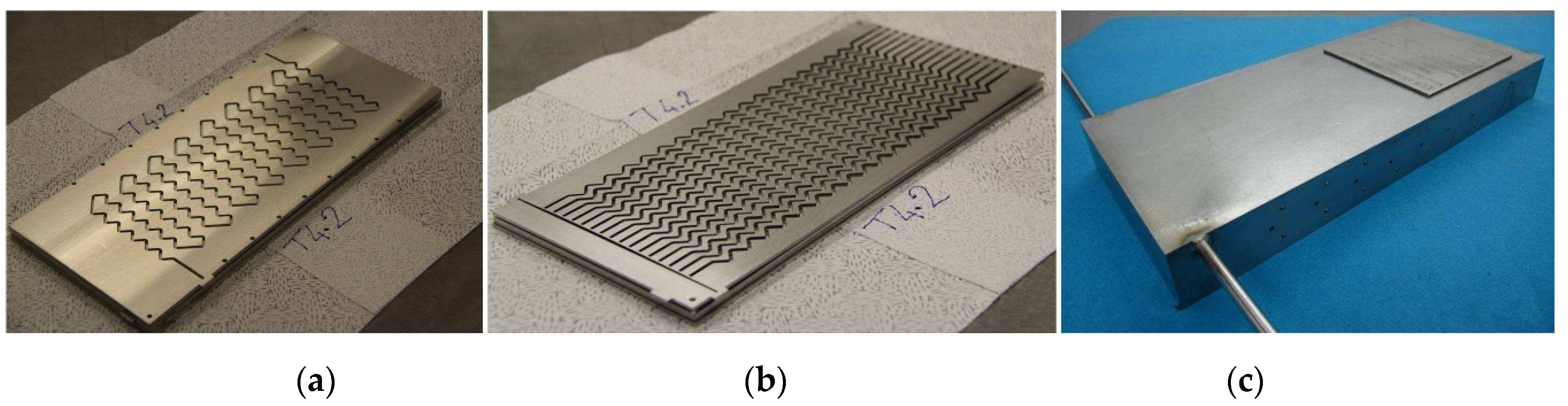
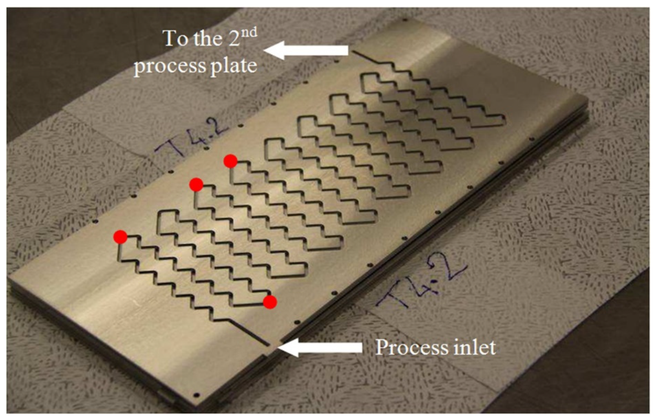
To show the validity of the general model presented in this paper, it was applied to a specific intensified HEX reactor with well-characterized performances. This reactor is based on the concept of plate heat exchanger in a modular block. It exhibits a plug-flow behavior, and is designed in such a way that reaction and heat transfer take place in plates. The pilot consists of three process plates sandwiched between four utility plates. The process plates, as well as the utility plates, have been engraved by laser machining to obtain 2 mm square cross-section channels. Process and utility channels are presented in
Figure 1a,b. The process fluid circulates in a single channel in order to offer the longest possible residence time for reactants, while the utility fluid flows in parallel zigzag-type channels so as to bring in or take reaction heat away as soon as possible. The characteristics of the pilot are detailed in
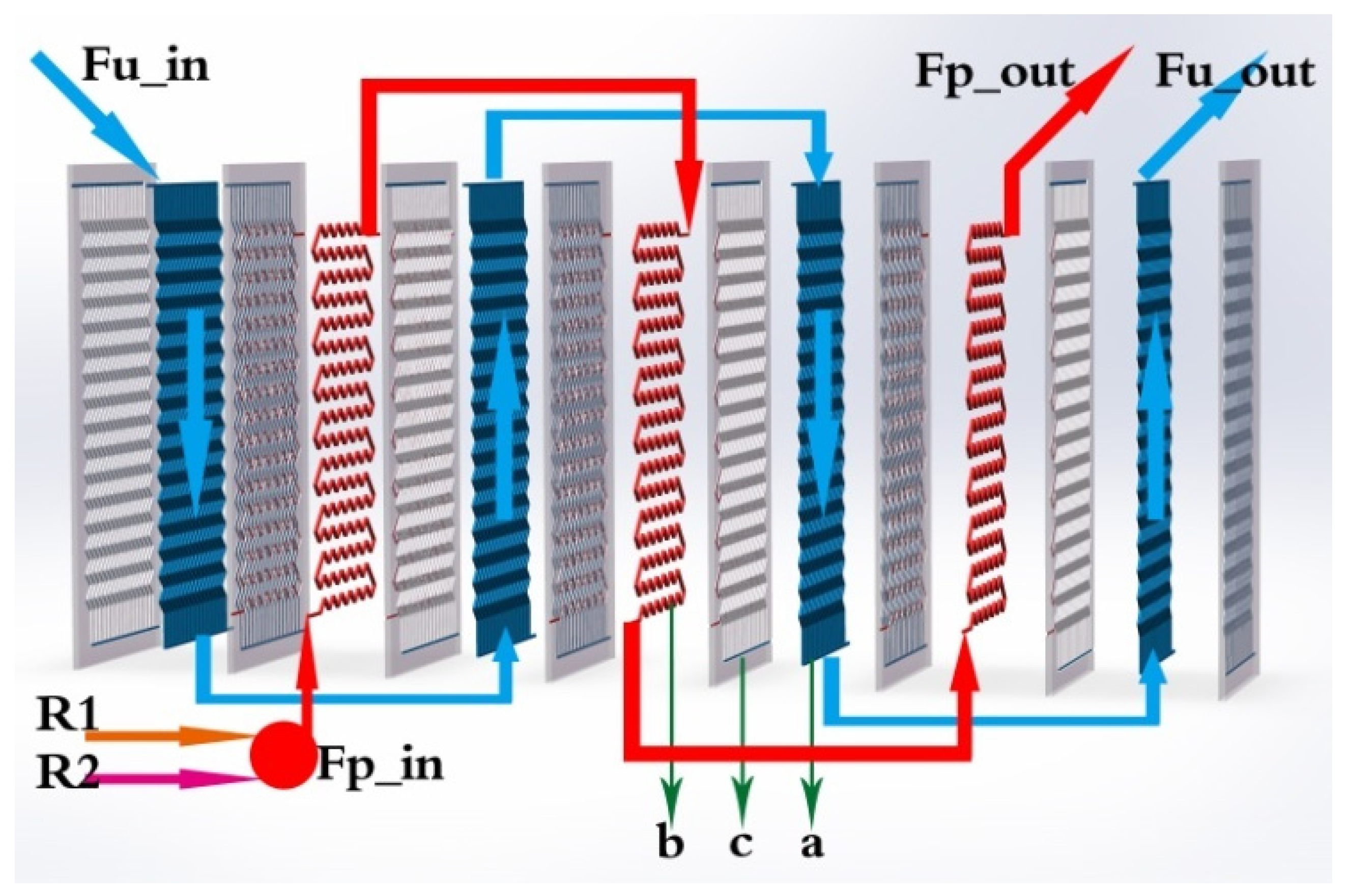
Table 1. The flow configuration of the two different fluids is shown in
Figure 2.
The reactor was manufactured from 316L stainless steel and different plates were assembled by hot isostatic pressing (HIP) [
28,
29,
30], which makes it very compact, with 32 cm height, 14 cm width, 3.26 cm thickness, and a mass of 10.84 kg. In order to find compromises between heat transfer, mixing performances, pumping power, compactness, and manufacturing costs, the process channel design was optimized in the vein of the RAPIC R&D project [
28,
29]. Geometrical parameters such as curvature radius, straight length between two bends, aspect ratio, and bend angle, which have a great impact on the thermal performance, residence time, and pressure drop distribution, were studied at lab scale [
10]. More details are described in a previous paper dedicated to the experimental study of the reactor [
10].
3. Modeling
3.1. General Modeling of the Reactor
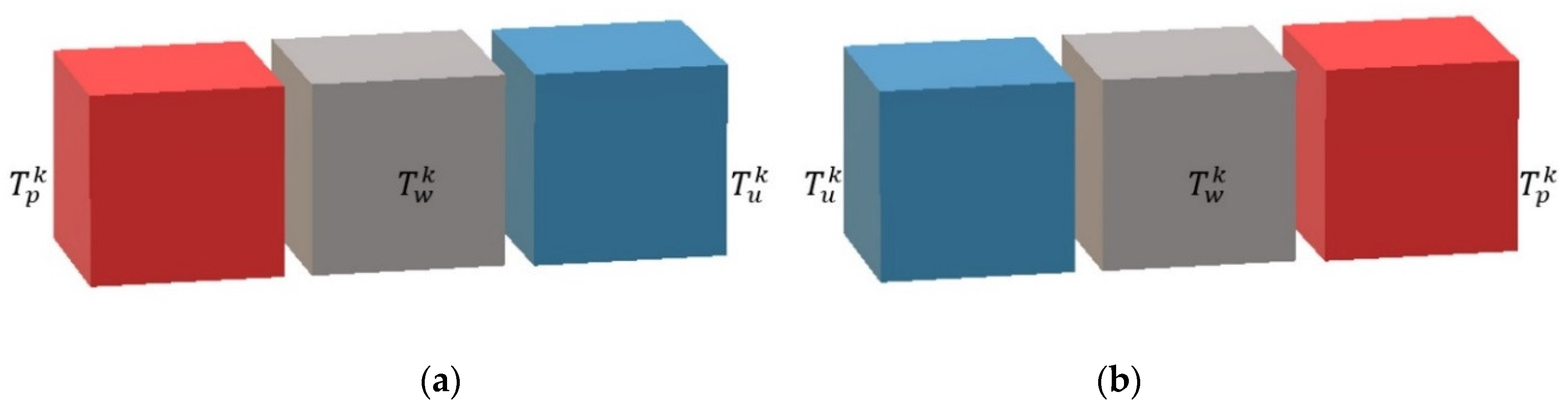
A realistic description based on a modular structure of the HEX reactor is presented in
Figure 2. Two (or several) feeding lines, the main feeding line (R1) and a secondary feeding line (R2), ensure that reactants could be introduced in the reactor. Two loops, process fluid and utility fluid, are in charge of reacting and cooling/heating, respectively. Arrows indicate the inner flow directions of the process fluid and utility fluid. It is obvious that there are three types of plates, which are denoted as a (utility plate), b (process plate), and c (plate wall) in
Figure 2.
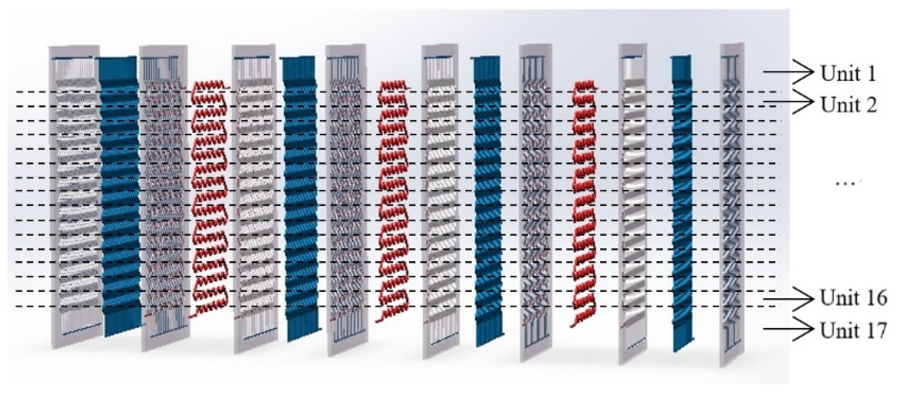
The pilot operates as a plug-flow reactor. Flow modeling is therefore based on the same hypothesis as the one used for the modeling of real continuous reactors [
31,
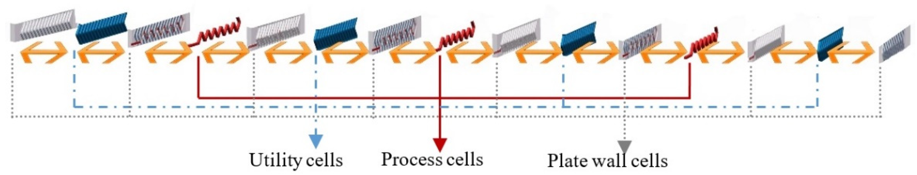
32]. The reactor is then represented by a series of perfectly stirred tank reactors (called cells). Generally, the number of cells could be defined according to the requirement of accuracy in concrete situations. To make a balance between model accuracy and calculation cost, and according to the geometry and the physical structure of the process channel, the reactor is divided into 17 computing units (see
Figure 3), as there are 17 horizontal lines in each process plate. Based on previous investigations [
10,
18], 17 can be considered an adequate number of units for a detailed model here. Each unit contains 15 cells (see
Figure 4): 3 process cells, 4 utility cells, and 8 plate wall cells. Therefore, the HEX reactor considered in this paper was divided into 255 cells in total. The far-right plate wall, as well as the far-left one, was covered by low heat transfer materials, so they are called adiabatic plates, i.e., there is no heat exchange between the reactor and environment. Thus, each process cell is a mini-reactor. It is obvious that convective heat exchange (see bi-directional arrows in
Figure 4) mainly takes place between neighboring cells in the horizontal direction inside one computing unit. The flows of fluids are the connections between neighboring units.
Such description makes it very easy to represent all possible flow configurations of the reactor (co-current, counter-current). In fact, it implies that the behavior of a cell only depends on the inlet streams and phenomena taking place inside: reaction, heat transfer, etc. Since the inlets of a given cell are generally the outlets of the preceding one, any configuration of flows may be represented by correct discretization. It can also be noticed that it is easy to generalize the model to any HEX reactor by applying the number of plates and the number of cells in the plate to the actual configuration of the reactor.
The modeling of a cell is based on the expression of mass and energy balance and constraint equations. The constraint equations aim to consider the geometric characteristics of the reactor and the physical properties of the medium mentioned. The balances are used to describe the relations of the characteristic values: temperature, mass composition, etc. according to the following formula:
Given the specific geometry of the reactor, three main parts are distinguished. The first one is the process plate, where complex hydrodynamics coupled with reactions and heat transfers are found. The second one is the utility plate, where hydrodynamic and heat transfers are involved. The third one is the plate wall, which is only concerned with the heat transfer aspect.
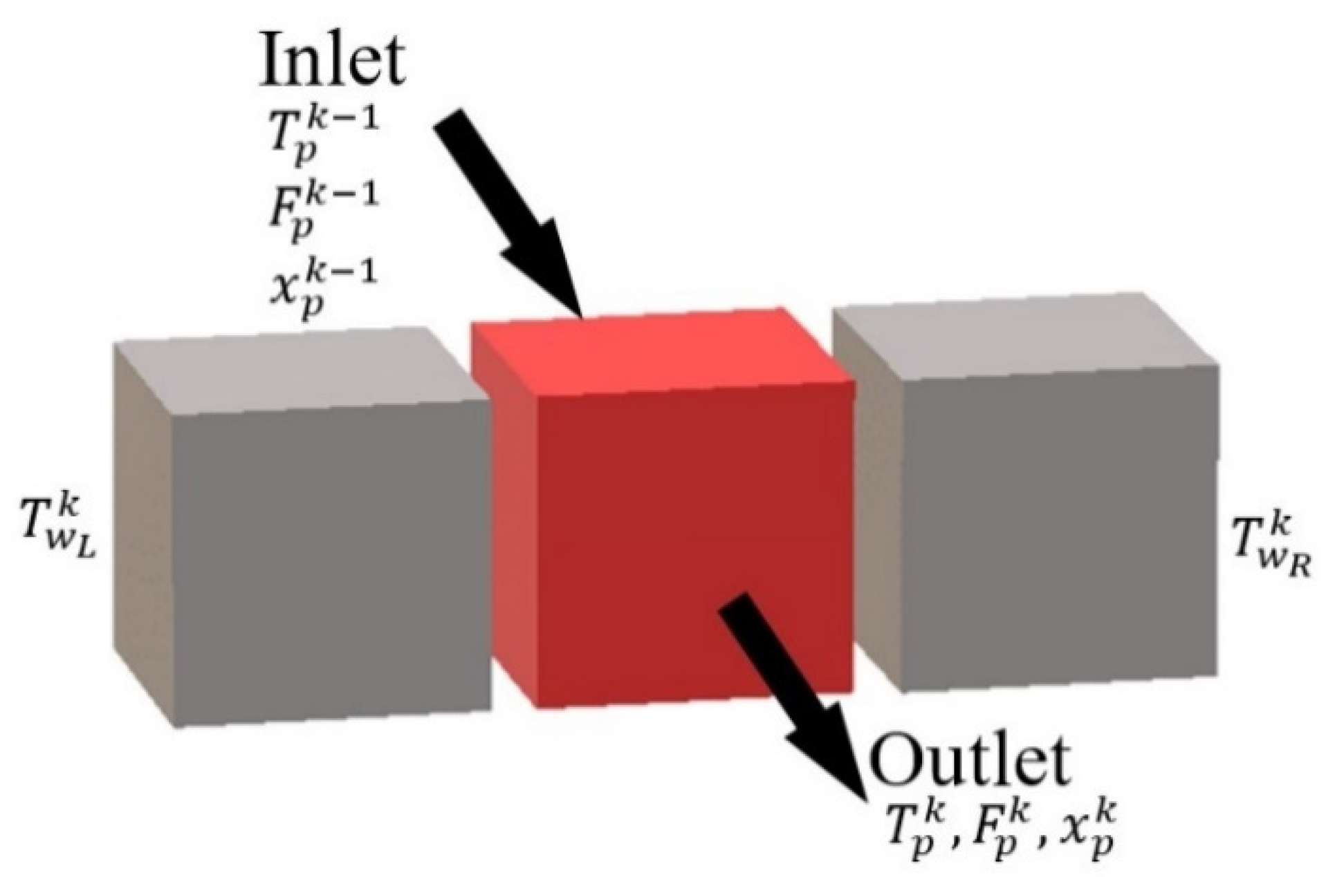
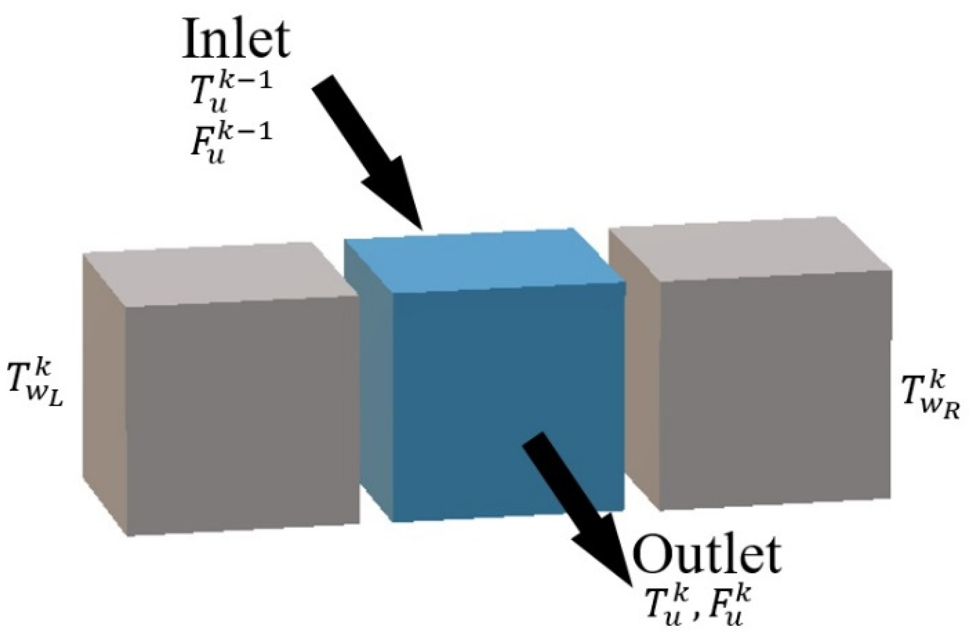
3.2. Modeling of the Process Plate
It was considered that the process plate is sandwiched between two plate walls (right and left). Moreover, the cells representing the process plate (see
Figure 5) are filled with a perfectly stirred homogeneous medium which has the following characteristics:
Homogeneity of characteristic values (temperature, flow rate, composition, etc.).
Homogeneity of physical properties (density, viscosity, etc.).
Homogeneity of chemical phenomena (mixing, reaction, etc.).
Invariable volume linked to the mixture of fluids (reactants).
The state and evolutions of the homogeneous medium circulation inside a given cell k are then described by the following balance and constraint equations:
Global mass balance (mol·s
−1):
where
(mol) denotes molar hold-up in process plate cell
k;
(mol·s
−1) represents molar flow rate in process plate cell
k;
(mol·m
−3·s
−1) is production rate of the reactions; and
(m
3) is volume of process plate cell
k.
Mass balance of component
i (mol·s
−1):
where
represents molar fraction of component
i in process plate cell
k.
Process energy balance (W):
where
(kg·m
−3) and
(J·kg
−1·K
−1) are density and specific heat of material in process plate cell
k, respectively;
(m
3·s
−1) is volume flow rate in process plate cell
k;
(K) is temperature in process plate cell
k;
(W·m
−3) denotes heat generated by the reactions in process plate cell
k;
(W·m
−2·K
−1) and
(m
2) represent heat transfer coefficient and area between process plate and plate wall for cell
k, respectively; and
(K) and
(K) are temperatures of left and right plate wall cells of the targeting cell
k.
Volume constraint (m
3):
where
(m
3) denotes maximum volume of cell
k.
Due to the fact that the process plates are channels embedded in plate walls in reality, for one process plate cell, which is assumed to be a cuboid, the surface connected between process cell and plate wall cell is the four-lateral area of that cuboid. Therefore, the heat transfer area between one process cell and one plate wall cell () actually equals half of the four-lateral area. According to the principle of cell partition, each plate has 17 cells. As the targeting HEX reactor has three process plates, the total number of process cells is 51.
Thus, heat transfer area between process plate and plate wall for cell
k is (m
2):
where
is four-sided lateral area of process channel and is computed as follows (m
2):
where
,
, and
(m) are length, width, and depth of process channel respectively.
The volume of process cell
k is (m
3):
where
is total fluid volume of process channel and is computed as follows (m
3):
3.3. Modeling of the Utility Plate and Plate Wall
To represent the reactor structure precisely, all the different heat transfer zones must be considered. Therefore, elements involved in the heat balance described by the model are as follows:
A utility plate (see
Figure 6) is sandwiched between two plate walls (right and left), and the description of heat transfer is as follows:
Energy balance on the utility fluid (W):
where
(kg·m
−3),
(m
3) and
(J·kg
−1·K
−1) are density, volume, and specific heat of material in utility plate cell
k respectively;
(m
3·s
−1) is volume flow rate in utility plate cell
k;
(K) is temperature in utility plate cell
k;
(W·m
−2·K
−1) and
(m
2) represent heat transfer coefficient and area between utility plate and plate wall for cell
k, respectively.
In the same way, utility plates are also channels embedded in plate walls. As the targeting HEX reactor has four utility plates, the total quantity of utility cells is 68.
Therefore, heat transfer area between utility plate and plate wall for cell
k (m
2) is calculated by:
where
is the four-sided lateral area of the utility channel and is computed as follows (m
2):
where
,
, and
(m) are length, width, and depth of the process channel, respectively.
The volume of utility cell
k (m
3) is given by:
where
is total fluid volume of the utility channel and is computed as follows (m
3):
A plate wall (see
Figure 7) is always sandwiched between a process plate and a utility plate, between which heat transfer is considered.
Energy balance on the plate wall (W):
where
(kg·m
−3),
(m
3) and
(J·kg
−1·K
−1) are density, volume, and specific heat of plate wall cell
k respectively;
(K) is temperature of plate wall cell
k.
Adiabatic plates assembled in both sides of HEX reactor are special plate walls, for which heat transfer is taking place between utility plate and environment. In this paper, it is assumed that the adiabatic plates are heat-insulated, i.e., that there is no heat transfer between adiabatic plates and the environment.
Energy balance on the adiabatic plate (W):
In fact, the plate wall cell cannot be assumed to be a cuboid, owing to the embedded channels. The exact value of the volume is obtained by its mass and density under the assumption of uniform distribution of the material. According to the dividing rules, the plant has 17 units, and each unit contains 8 plate wall cells. Thus, there are 136 plate wall cells in total.
The volume of plate wall cell
k (m
3) is calculated as:
where
(kg) and
(kg·m
−3) are mass and material density of the HEX reactor.
3.4. Calculation of Heat Transfer Coefficient
As mentioned in
Figure 7, the heat transfer process is divided into two parts: one is the convective heat exchange between the process channel and the plate wall, the other is between the utility channel and the plate wall. Therefore, the heat transfer ability, which is denoted by multiplying the overall heat transfer coefficient (
U) and the overall heat transfer area (
A), can be calculated by the convective heat transfer coefficient of the process fluid side to plate wall (
) and heat transfer coefficient of plate wall to utility fluid side (
), which is generally defined by the following Equation (18):
where
(W
−1·K) is thermal resistance or fouling parameter in channels. For a clean HEX reactor,
Rf is considered to be negligible.
For calculation of the overall heat transfer coefficient through pipes and channels, the Nusselt number, which represents the ratio of convective to conductive heat transfer, is an important dimensionless number. In the case of this paper, fluids inside the channels are all assumed to have the same thermal characters as water and there is no phase change. Thus, for this given HEX reactor (i.e., size, structure, and material fixed), the Reynolds number is the dominant variable in the equation of calculating
. Besides, when computing the Reynolds number, the flow rate of the fluid becomes the key variable, because other parameters will have very small changes. Therefore, it can be assumed that the convective heat transfer coefficients are functions of mass flow rate and physical properties of both fluids (process and utility). For simplicity, they could be defined as linear functions in the normal operation domain, as follows:
where
and
are two scalar factors; and
and
(kg·h
−1) are mass flow rates in process and utility plate, respectively.
Substitute Equations (19) and (20) into (18), then:
Experimental data concerning the HEX reactor considered in this work (see
Table 2) are available, and some of them have been reported in a previous paper [
9]. Using the same calculation method as in Reference [
9], several values of
could then be obtained. As heat transfer area
and
are fixed according to the geometrical properties of the HEX reactor, a genetic algorithm was introduced to search a group of optimal value for
,
and
. The fitness function of the genetic algorithm is defined below:
where
is the value of
calculated from data of
experiment, and
and
are mass flow rates of process and utility channels in the
experiment.
The fitness function guides the genetic algorithm to find a relatively minimal total error of Equation (21) towards experimental data. When the goal is achieved, the targeting values of
,
, and
are found. For all the experimental data available in
Table 2, we randomly reserved Experiment 5 and Experiment 8 for validation of the heat exchange simulations in
Section 4. Other data of experiments in
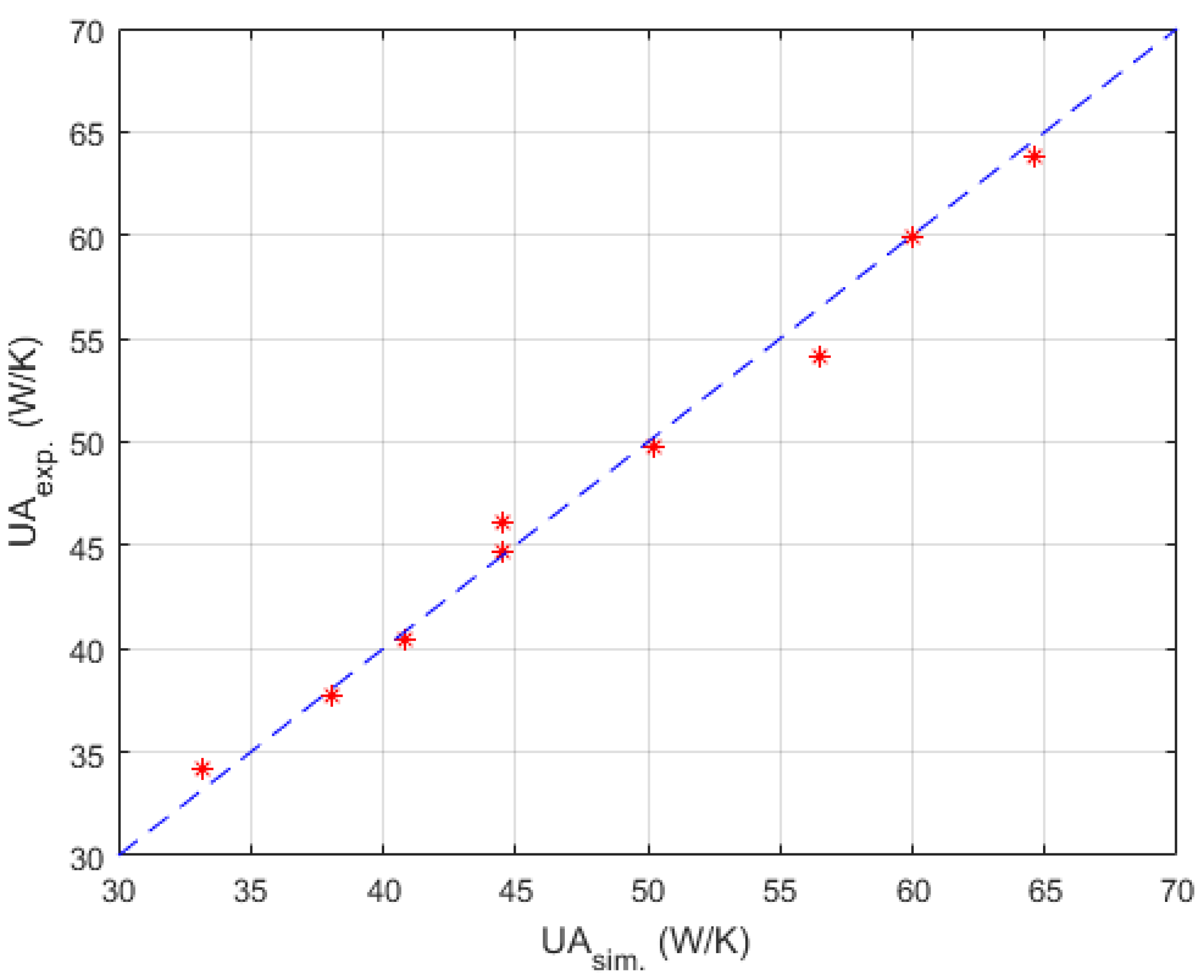
Table 2 were used here for searching relatively optimal parameters mentioned above. To prevent the algorithm dropping to a local optimal too early, the number of individuals in one generation and the number of evolutionary generations were set to 5000 and 1000 respectively. Satisfactory results were searched out, and the corresponding parity plot is shown in
Figure 8.
Parameters searched by genetic algorithm are W·m−2·K−1·kg−1·h, W·m−2·K−1·kg−1·h, W−1·K. As mentioned before, is negligible. The confidence intervals depend mainly on the temperature difference between the process fluid and utility fluid. Generally, this varies from 10% to 15% of the nominal value. Thus, and were obtained in satisfactory accuracy with Equations (19) and (20).
3.5. Reaction Modeling
In order to demonstrate the advantages of the HEX reactor, experiments were carried out step by step in Reference [
9].
To validate the model, the preliminary step concerned experiments with water to verify the thermal description of the reactor and the behavior of related thermal correlations. In the second step, experiments with the reaction of sodium thiosulfate oxidation by hydrogen peroxide carried out in the reactor were considered.
The reaction takes place in a homogeneous liquid phase and shows the following characteristics: irreversibility, fast kinetics, and very strong exothermicity. These features make it an ideal example for validation of the thermal and kinetic aspects of the HEX reactor and its model.
The speed of the reaction is determined by the concentration decrease of the reactants over time. As the reaction goes, the concentrations of the reactants gradually decrease.
Knowing the speed of a reaction makes it possible to estimate the rate of production for a given constituent (), the total production rate (), and the heat generated (). These estimations, which are used within the mass and energy balance of the cell, are based on the following relations:
The production rate of constituent
i:
where
represents stoichiometric coefficient of constituent
i in reaction
j.
Heat generated:
where
is the heat of reaction
j (J·mol
−1).
For the reaction of sodium thiosulfate oxidation by hydrogen peroxide,
is [
9]:
In this paper, the kinetic constant of reaction was assumed to be governed by an Arrhenius law, which made it possible to estimate the evolution of the constant as a function of temperature:
where
(
) is the pre-exponential factor of the reaction
j;
(J·mol
−1) is activation energy of reaction
j; and
(J·mol
−1·K
−1) is the perfect gas constant.
The following values, given in Reference [
6], were implemented in the model:
Considering the stoichiometric scheme of the reactions and Equations (23) to (26), the concentration of each reactant in a cell behaves according to the following relationships:
where
and
(mol·m
−3) are the concentrations of
and
in process cell
k, respectively; and
is the speed of a reaction
j taking place in cell
k. It is expressed as a function of the concentrations of the reactants, as follows:
where
(m
3·mol
−1·s
−1) is the kinetic constant of the reaction and is given in Equation (26).
3.6. Calculating the Model in Matlab/Simulink
The formulation of the model leads to a hybrid differential and algebraic equations (DAE) system. Ordinary differential equations (ODE) (Equations (2), (3), (10), (15), (16)) contain mass and energy balances. Algebraic equations (AE) (Equations (5), (19)–(21)) consist of the reactor constraints and physical properties estimation equations. This DAE system presents a strongly nonlinear nature, mainly resulting from the modeling of the chemical reaction.
The system was modeled and simulated in Matlab/Simulink. One unit consisted of three process plate cells, four utility plate cells, and eight plate wall cells. Each cell here was called a calculating module. For process plate cells, both mass and energy balance equations were introduced in the module to take into account the evolution of the temperature and the concentrations of the components due to heat transfer and to the reaction. For utility plate and plate wall cells, only energy balance equations were considered.
Therefore, the complete pilot was represented by the connection of 17 units. For each unit, multiple inputs and outputs concerning cells in other units were elicited to connect to associate ports.
As shown in
Figure 2 and
Figure 3, for utility fluid, the temperature output of utility plate cell 1 in unit 1 would be connected to the temperature input of utility plate cell 1 in unit 2. For that of unit 17, it is different; the temperature output of utility plate cell 1 in unit 17 would be connected to the temperature input of utility plate cell 2 in unit 17 itself.
For process fluid, the fluid was injected at process plate cell 1 in unit 17 due to the opposite flow direction between process fluid and utility fluid. Afterward, the temperature input of process plate cell 1 in unit 16 came from the temperature output of process plate cell 1 in unit 17. The temperature output of process plate cell 1 in unit 1 was linked to process cell 2 in unit 1.
Therefore, in accordance with the general scheme of the reactor presented in
Figure 2, outputs of process fluid corresponded to data of cell 3 of unit 1, and outputs of utility fluid to these of cell 4 of unit 1.
These connections maximized the heat transfer efficiency, thus, the heat generated by reactions was rapidly taken away by utility fluid. According to the manner of the connection, heat exchange mostly took place horizontally, i.e., between different kinds of cells inside a unit, due to the thin plate structure of the reactor. As a consequence, 15 cells of different plates were packed in one unit, and the heat exchange was dealt inside while the fluid flow was handled outside the unit.
6. Conclusions
In this paper, the modeling process of an intensified HEX reactor is presented in detail, which is different from previous studies in the introducing of the chemical reaction, the modeling platform, and the combination of the physical structure and thermal features of the model. At first, the physical structure was studied, and the continuous process was discretized into cells. Consequently, the representative equations of each cell were given under the consideration of heat exchange, fluid movements, and chemical reaction. These differential equations were introduced in the general simulation platform, Matlab/Simulink. After that, three parameters concerning the heat transfer coefficient were searched by genetic algorithm, and a non-linear model of 255 basic calculating modules was developed. Finally, several simulations were launched in different working conditions to make comparisons with the experimental data.
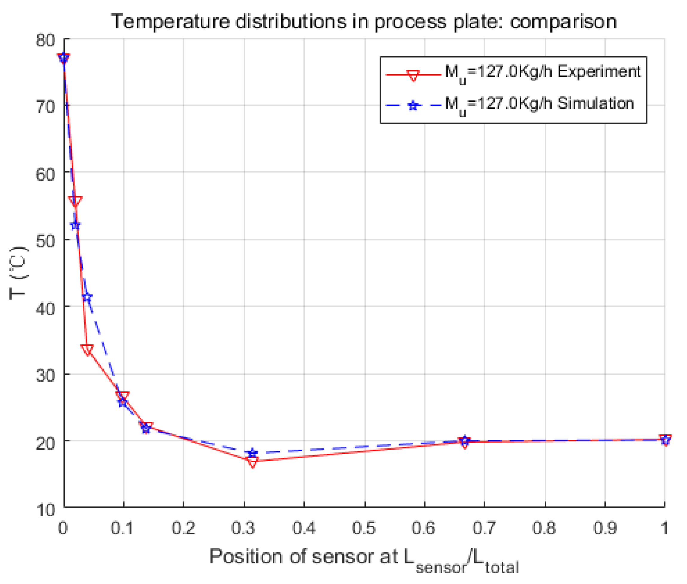
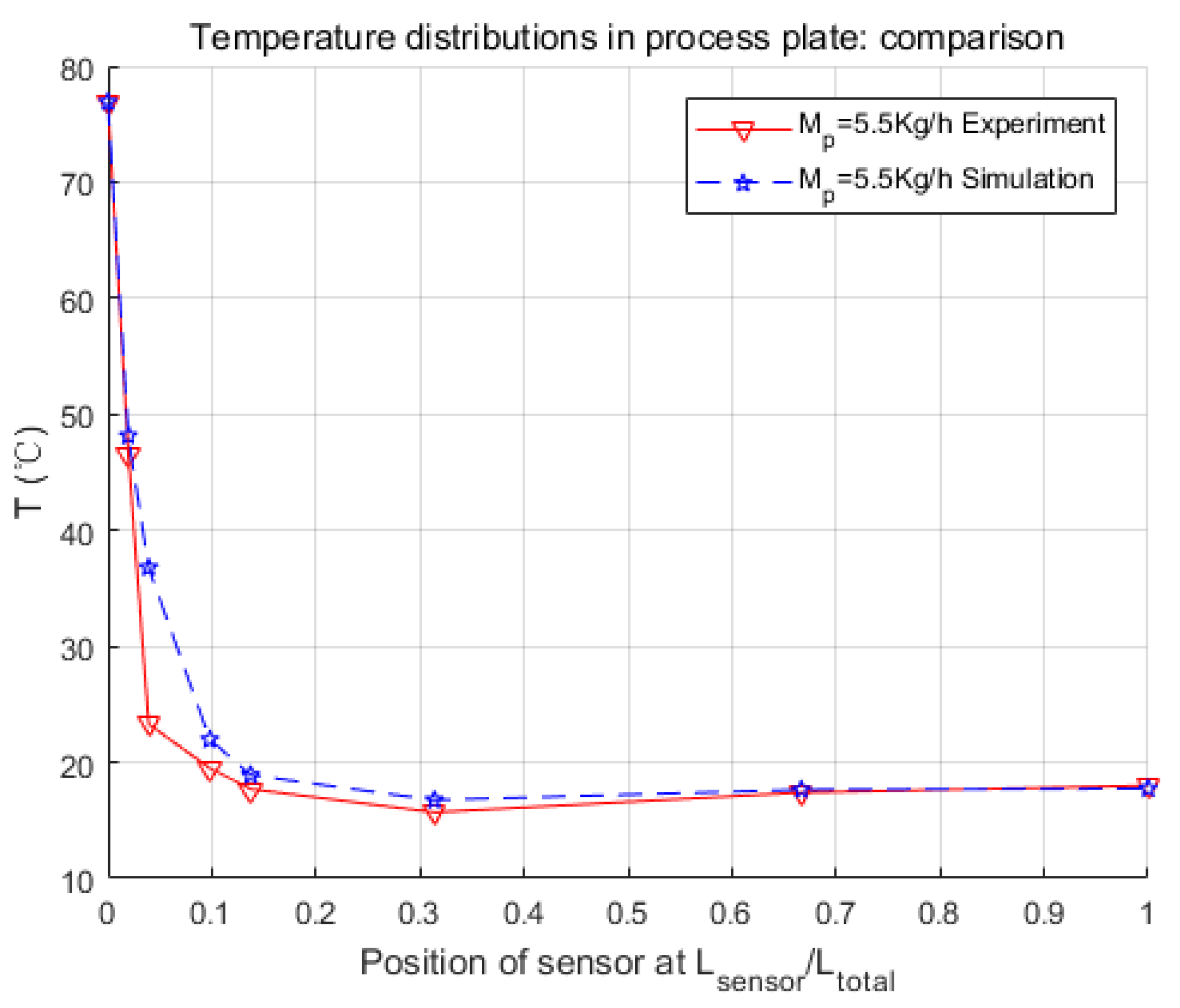
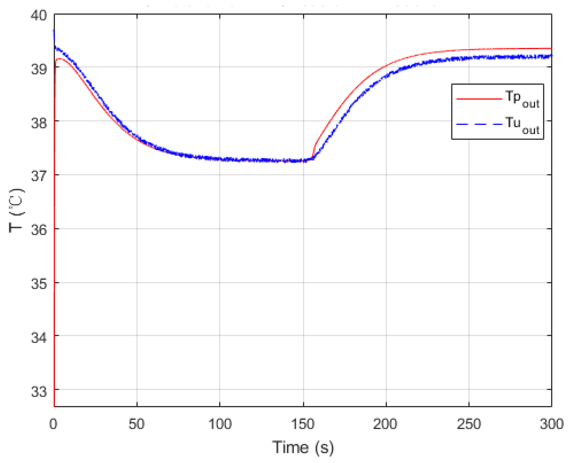
Simulation results were quite consistent with the experiments. For the heat exchange part, this model had very accurate inner temperature distributions toward the HEX reactor. For the reaction part, this model also performed well, in that it generated good dynamic curves, as the physical one did. Furthermore, conversion rate, which is a crucial parameter to a chemical reactor, could be easily and precisely computed from the concentration loss of reactants in the model. Thus, it could be concluded that the nominal model obtained in this paper is accurate and equivalent to the real HEX reactor. One thing should be mentioned is that the modeling methodology implemented in this paper is not restricted, and could also be used for other reactions and other sizes of HEX reactors by replacing parameters to specific reactions or reactor size. The cell number could also be optimized to meet the requirements of accuracy, calculation consumption, or consistency to the physical reactor.
The purpose of modeling the HEX reactor is for further control use. With the model developed in this paper, internal states, as well as conversion rates, were easily achieved while simulating. Algorithms like model-based observers could be designed and validated conveniently on this model. These algorithms can then be used for developing approaches like fault detection, isolation, identification, and fault-tolerant control, which could be implemented on real plants to improve the performance of HEX reactors on safety, efficiency, and productivity.


