1. Introduction
Energy demand has prompted different approaches recently due to limited energy resources as well as technical and environmental constraints. As fossil fuel sources are depleting, energy optimization and upgrades of plants have become crucial to narrow the gap between energy supply and demand. In the literature, there are various strategies to achieve energy optimization in industrial processes. Research and development units in the industry are focusing on maximizing individual units’ throughputs following local and global economics. However, due to operational and forecasting constraints, they are faced with challenging trade-offs. As a result, retrofit of existing plants offers a viable alternative to overcome operational requirements.
Retrofit plans in heat exchanger networks (HEN) include reducing the use of utilities, upgrading heat transfer units, installing additional heat transfer area, re-piping streams and re-assigning new heat recovery matches. HEN is a heat recovery system that enables heat exchange between hot and cold streams in chemical process plants, which is essential for energy conservation within a plant. The grass-roots design of HEN as studied by Linnhoff et al. has been significantly improved through the use of Pinch Technology [
1,
2,
3]. Tjoe and Linnhoff were the first to propose a systematic methodology for heat exchanger network retrofit using pinch analysis [
4], based on the elimination of any cross-pinch match by disconnecting units that transfer heat across the pinch. Gadalla et al. have presented a methodology to maximize the use of existing equipment in HEN and distillation column based on rigorous simulation and optimization framework using pinch analysis [
5]. Biyanto et al. have recently conducted a HEN retrofit for maximum energy recovery without topological changes using a genetic algorithm (GA) to screen different optimization scenarios for selecting optimum heat transfer coefficient [
6]. A step-wise approach for optimal HEN retrofit to reduce calculation times and annualized cost associated with HEN complexity has recently introduced by Ayotti-Sauve et al. [
7]. Kang and Liu have conducted a comprehensive review and analysis for the synthesis of flexible HEN, including both grass-roots and retrofit design [
8].
Different methodologies have been developed based on the concept of utility path analysis in HEN such as those developed by Varbanov and Makwana [
9], where they first presented the rule of path construction for HEN retrofit. Van Reisen et al. have proposed a method of path analysis for decomposition and prescreening of HEN [
10]. Their technique selects and evaluates only potential subnetwork parts of the existing HEN. In subsequent work, Van Reisen et al. have presented an extension to the path analysis procedure, by considering structural interconnections while solving the retrofit problem [
11]. They divided the network into many sub-networks by a combination of structural units using path analysis. These units, called zones, must be as self-contained as possible, similar to the approach used in grass-root problems. Paths help to classify the zones that are better suitable to include structural modifications. The refined path zones are based on functions of plant sections as well as operational constraints such as temperature range of process streams. For enhancing the process-to-process heat recovery in HEN, Osman et al. have introduced a combinatorial approach of paths combination [
12]. Their strategy depends on shifting heat loads through utility paths at the constraint of heat recovery approach temperature (HRAT) and exchanger pressure drop. In subsequent work, Osman et al. applied the same methodology to screen more extensive options of heat recovery enhancement in HEN with an option of varying HEN streams temperature [
13].
Awad and Abdelgadir have conducted two different studies for energy saving in HEN of crude oil pre-heat train unit using the paths combination approach. However, they did not consider the effect of pressure drop while estimating the heat transfer coefficient in HEN devices [
14,
15]. They also ignored the emission of CO
2, although the main heater of the network is using heavy fuel.
HEN Retrofit study considering the constraints of the pressure drop in HEN was first recognized by Polley et al. [
16]. Comprehensive research considering the pressure drop in HEN retrofit was conducted by Panjehshahi [
17], Marcone et al. [
18] and Gadalla [
19].
Regarding HEN area distribution, along with economic assessment, Lai et al. have introduced a recent study where they presented a new customized approach for HEN retrofit [
20]. They used a combination of individual stream temperature versus enthalpy to map hot and cold streams to minimize the overall heat exchanger area. They also used graphical cost screening tool and strategies to steer and customize HEN retrofit design toward a desired investment payback period.
Regarding environmental pollution outstretched from process plants, significant efforts and strategies have been made by Steyn [
21] and John [
22] to provide CO
2 emissions reduction solutions. These strategies include improving the energy efficiency in process plants and fuel switching as well as renewable energy technologies such as carbon capture and storage (CCS). Gadalla et al. have developed a simple approach for optimizing the process conditions of industrial units to reduce its CO
2 emissions and energy demands [
5].
Kang and Liu have conducted a recent work by developing a systematic strategy for HEN retrofit to minimize total annual cost and CO
2 emission. Based on a multi-objective optimization model [
23].
Most of the previous work conducted for energy saving in process plants were associated with costly topological changes in HEN. Such changes were either addition of new heat exchangers, re-piping or resequencing the existing devices. However, topological changes always require additional space (platform) in the plant, which might be unavailable or/and restricted for safety consideration. Topological changes also associated with civil work and have not been considered in previous studies.
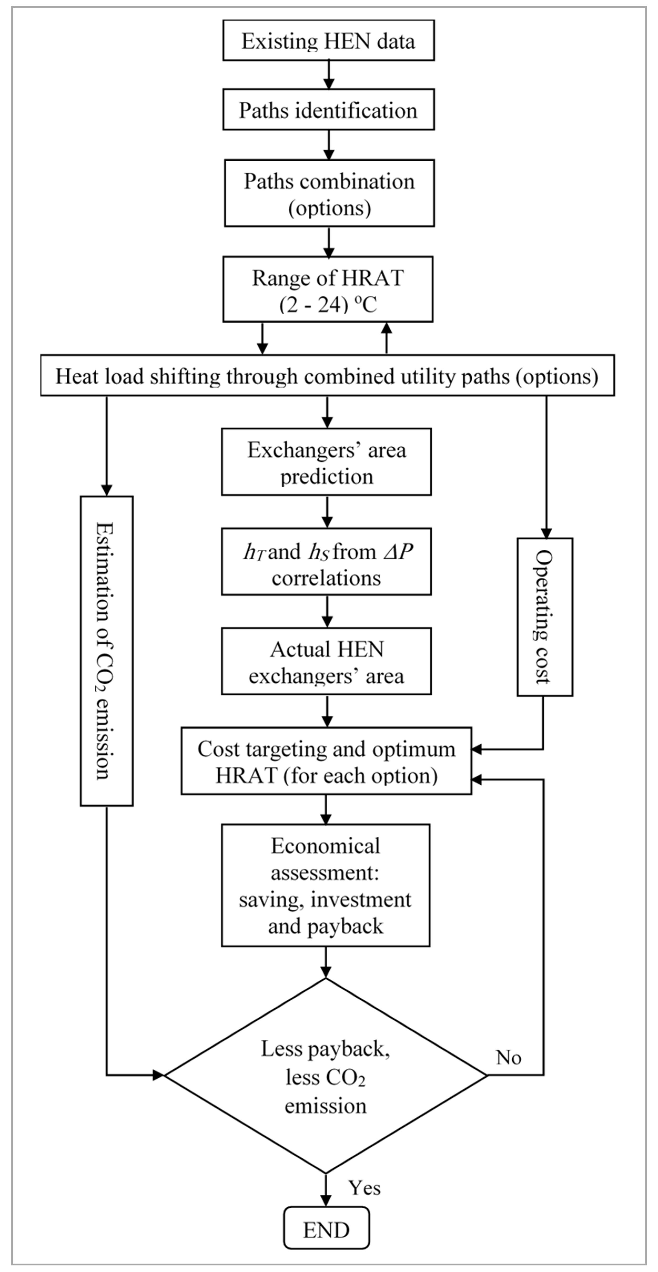
Accordingly, in this work, the authors carried out energy optimization for an existing HEN (crude oil preheat train unit) using the combinatorial approach of path combination. Apart from the previous works of the authors that based on a fixed value of HRAT while ignoring the effect on CO2 emission, the current work is conducted at different HRAT values considering the cost targeting approach, exchangers’ pressure drop, and the impact of energy saving in HEN on CO2 emissions.
3. HEN Case Study
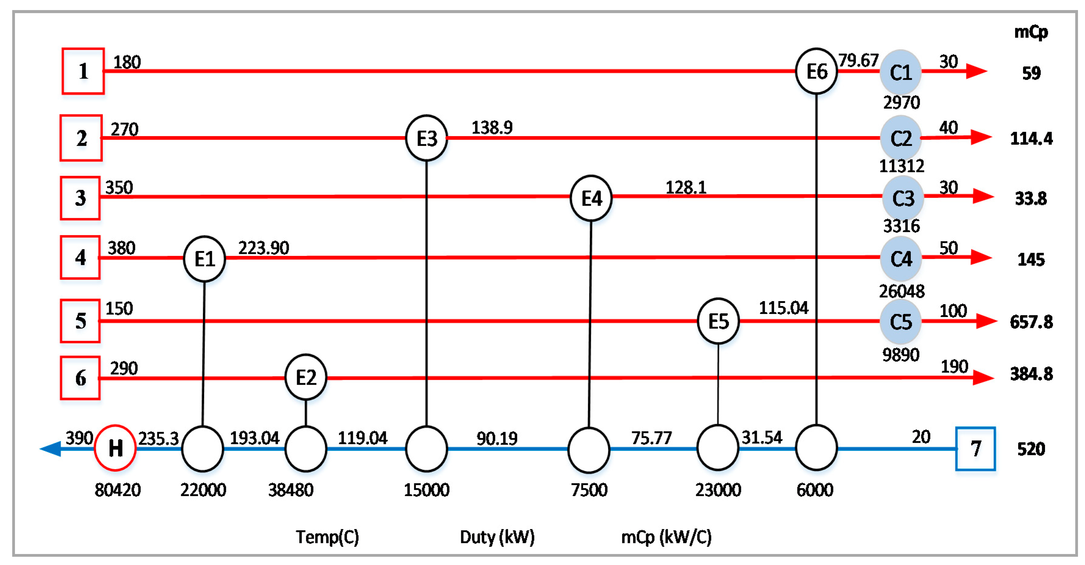
The case study adopted in this work is a HEN for a pre-heat train of a crude oil distillation unit taken from Panjishahi and Tahouni [
29], Awad [
14] and Abdelgadir [
15]. The schematic representation of HEN with stream data (temperature, exchanger heat load, the duty of hot and cold utility, and specific heat mass flow) is shown in
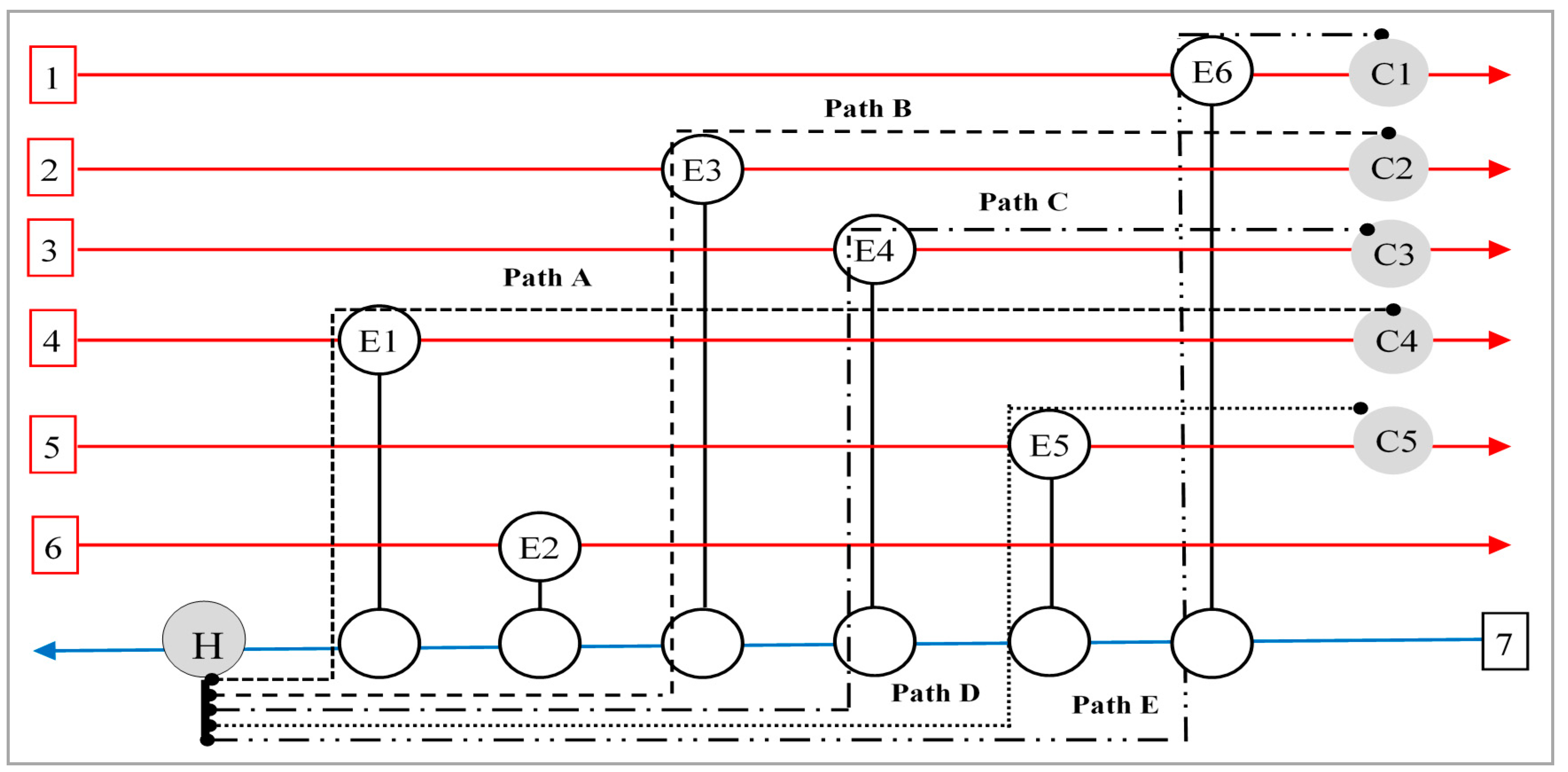
Figure 2. The available utility paths in such HEN are identified separately as in
Figure 3.
The paths combination approach has been used by Abdelgadir [
15] to generate several options of heat-shifting in HEN of a pre-heat train unit while ignoring the exchangers’ pressure drop. However, only three options were found feasible in terms of optimum HRAT value. These best options are adopted in this study for further analysis considering exchangers’ pressure drop and the effect of energy saving on CO
2 emission. The selected options are listed in
Table 1.
According to a previous study by Panjeshahi and Tahouni [
29], hot and cold utility prices for the preheat train are tabulated in
Table 2:
All the data (including equations) required to estimate the heat transfer coefficients for shell and tube sides of the exchangers are available in the Appendix. Geometrical configurations and fluid properties of exchangers are used to calculate the exchanger pressure drop. Heat duty is used to calculate the exchanger heat transfer area. Then both exchanger pressure drop and heat transfer area are used to calculate the heat transfer coefficients [
24].
Furnace fuel used as HEN hot utility reacting with excess air (O
2) produces flue gases including CO
2. It is assumed that the fuel in the furnace is fuel oil with a carbon content of 87.26% and net heat value
NHV of 39,830 kJ/kg is fed at 25 °C with air at the same temperature [
30].
4. Results and Discussion
The optimum HRAT value for HEN that corresponds to the lowest total cost can be obtained from the cost targeting profile of Pinch Technology. It is worth mentioning that the total cost is a summation of operation and annualized capital costs. Therefore, heat-shifting options may reveal similar lower total cost but with different HRAT values where the higher is preferred as a heat transfer driving force.
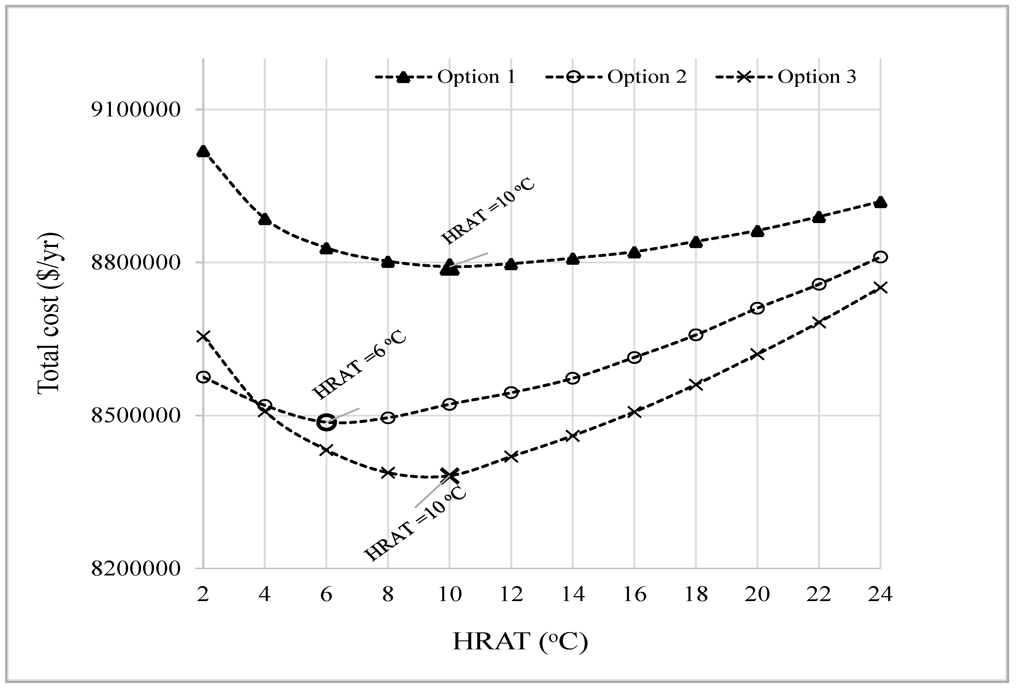
Figure 4 illustrates the cost targeting profile for the three options of heat-shifting in the HEN example used in this study. Compared to options 1 and 2, it is clear that option 3 shows the best profile of total capital cost to be lowest at 8.38 × 10
6 $/yr corresponds to optimum HRAT of 10 °C. Although the optimum HRAT value shown in the profile of option 1 is 10 °C (similar to that of option 3), but the total cost is higher. In contrast, option 2 illustrates the same trend that is showing a low total cost of 8.5 × 10
6 $/yr at lower optimum HRAT value of 6 °C, which can be insufficient heat transfer driving force.
It worth mentioning that option 3 is having the most degrees of freedom where it contained all the HEN paths from A to E. However, the targeting process yields higher total cost for option 3 than option 2 at the lowest HRAT value. That is because option 3 is affecting all HEN exchangers where the additional area is required for them all, and hence increasing the capital and total cost. The
Appendix A Table A11,
Table A12 and
Table A13 show a detailed area distribution in HEN using the three options.
The external energy requirements for options 1, 2 and 3 are determined from the energy consumption profiles.
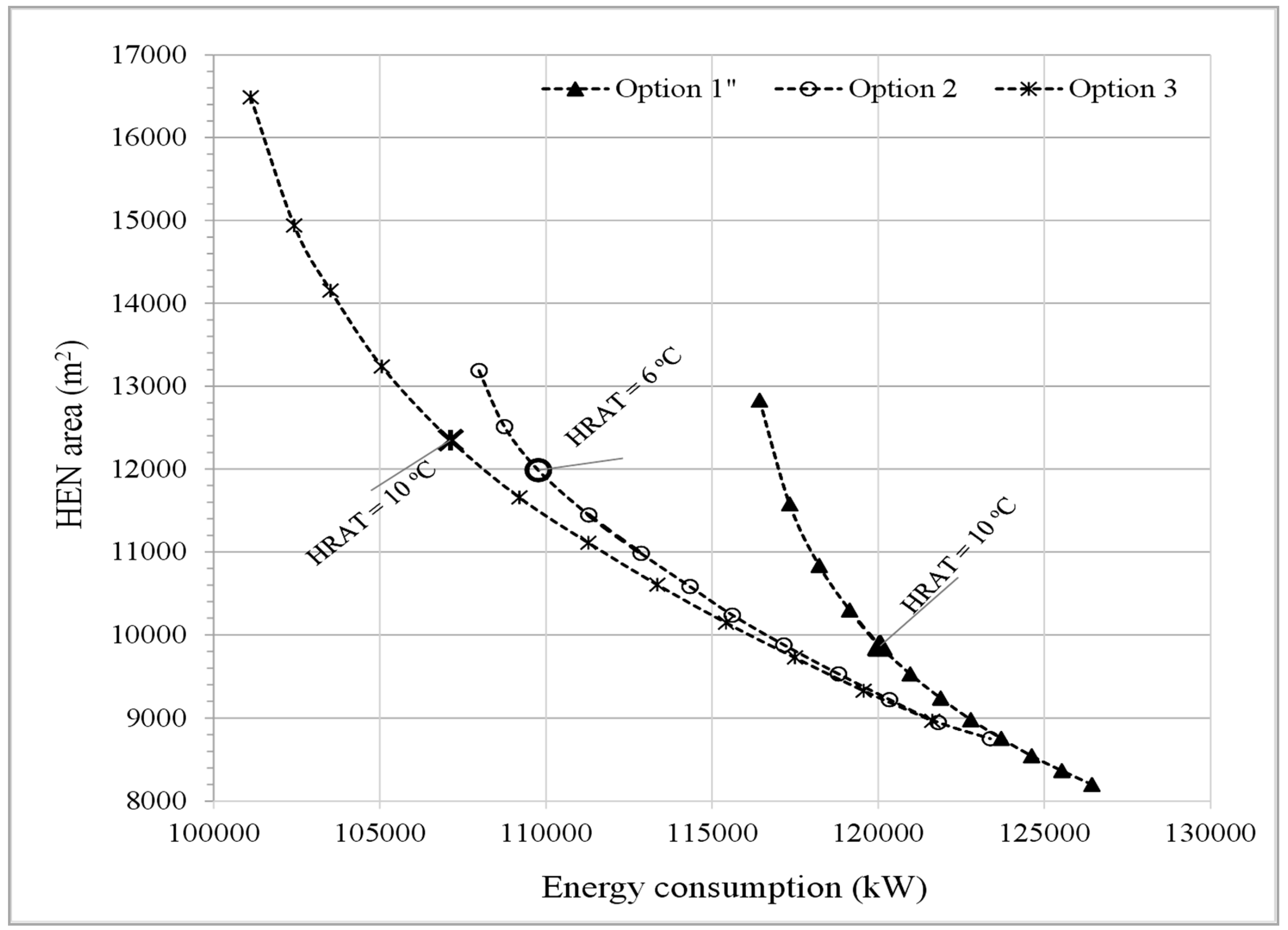
Figure 5 shows the energy consumption profile, which has been reduced due to the heat-shifting process at the penalty of additional heat transfer area for options 1, 2 and 3. The pattern of option 3 (a combination of utility paths: A, B, C, D and E in HEN example) indicates the lowest energy consumption and reasonable heat transfer area requirements. Using option 3 at the optimum HRAT of 10 °C, energy consumption has dropped from 1.34 × 10
5 kW for the present case to 1.07 × 10
5 kW, where 2.7 × 10
4 kW of external energy usage is saved. The additional area requirement is distributed through all the affected exchangers in HEN, which is 5390 m
2 where it increased from 6960 m
2 to be 12,350 m
2 at optimum HRAT value of 10 °C. The area requirement for option 1 is the lowest compared with option 2 and 3; however, energy consumption is trending very high. Option 2 is trending close to option 3 and even better in terms of area requirement, but the optimum HRAT value is low.
A complete area-energy trade-off can make the right decision to choose the best energy saving option. Therefore, these options are studied economically where the profiles of investment ($), savings ($/year), and payback periods (yr) are analyzed concerning HRAT to select the most excellent option.
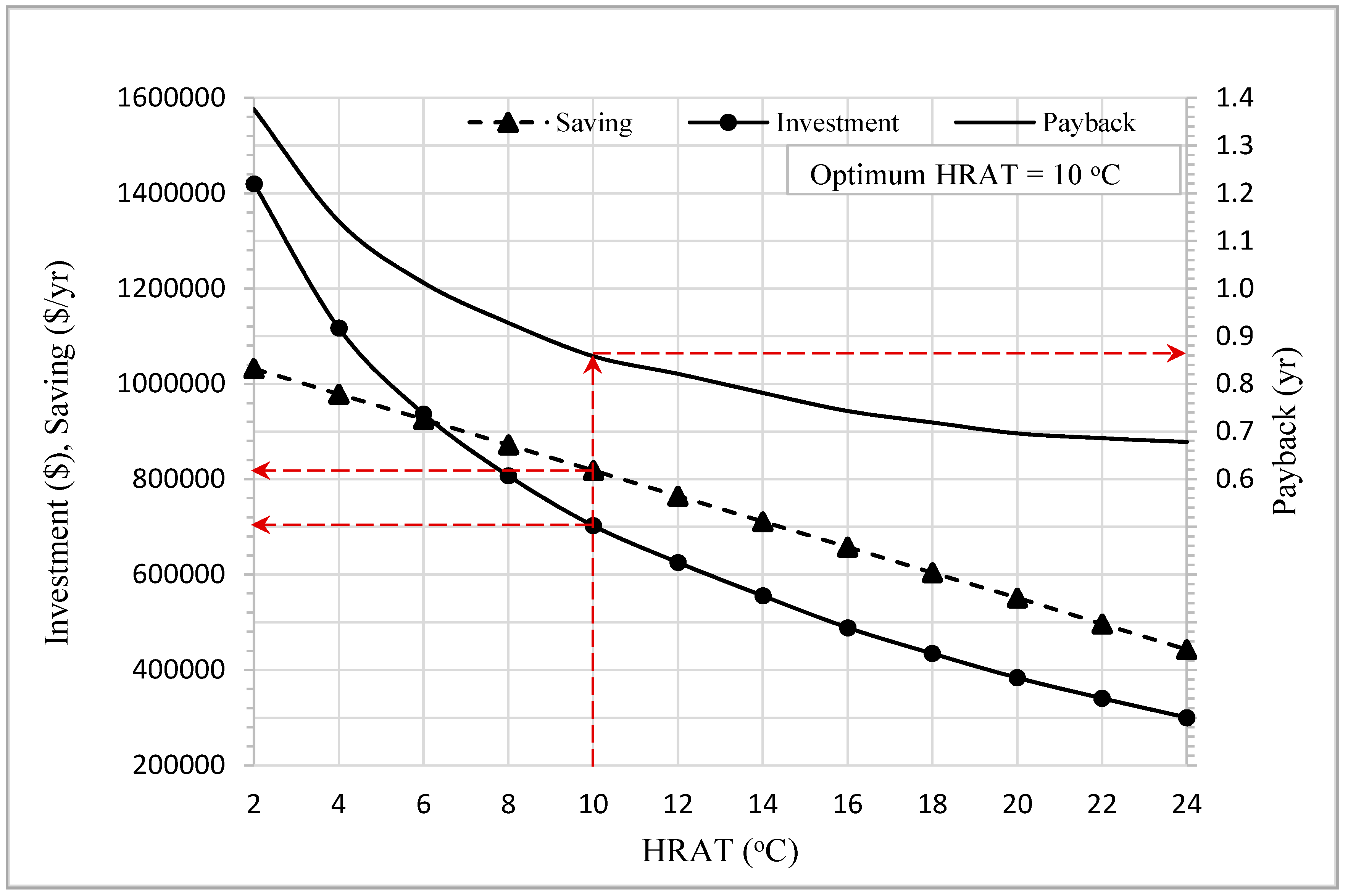
Figure 6 illustrates the economic profile of option 1. The economic profile shows a gradual decrease in investment, savings, and payback with increasing HRAT. When HRAT increased from 2 °C to the optimum HRAT of 10 °C, the investment cost has dropped by 50%. On the other hand, savings have slightly decreased from 1000K
$/yr to around 800K
$/yr at optimum HRAT. The payback has tremendously decreased from 1.4 yr to approximately 0.86 yr at optimum HRAT of 10 °C.
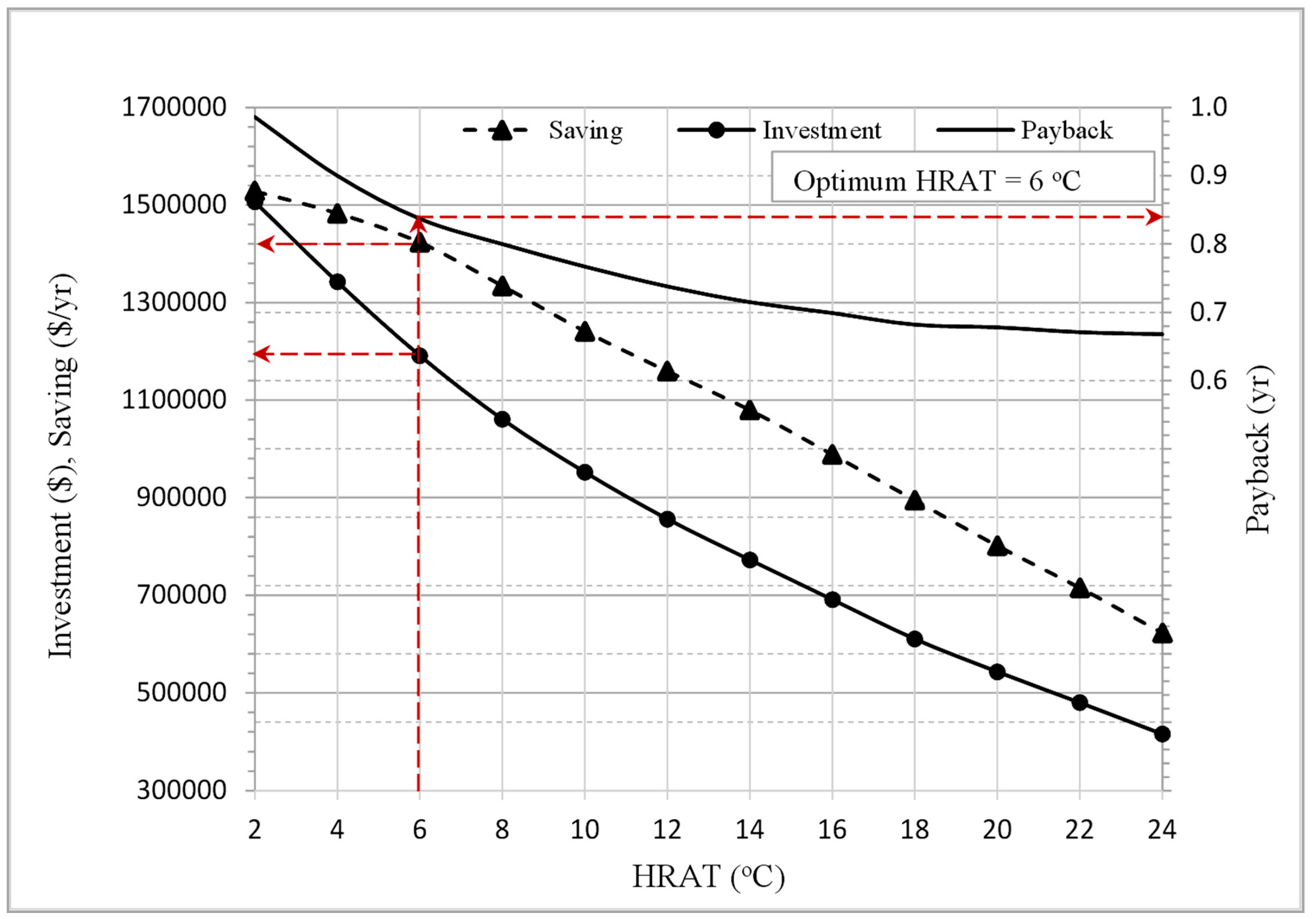
Figure 7 illustrates the economic profile of option 2. While the ratio of saving to investment started at almost 1 (superimposed saving and investment at HRAT of 2 °C), it became higher with higher HRAT values. Although, this option is showing a short payback period of 0.84 yr, the optimum HRAT of 6 °C makes it insufficient for the heat transfer process between hot and cold streams. This option can be operable by applying some constructional changes in HEN to relax the HRAT value at the expense of higher investment and payback. The constructional changes may include the addition of new HEN devices, exchanger resequencing, and re-piping.
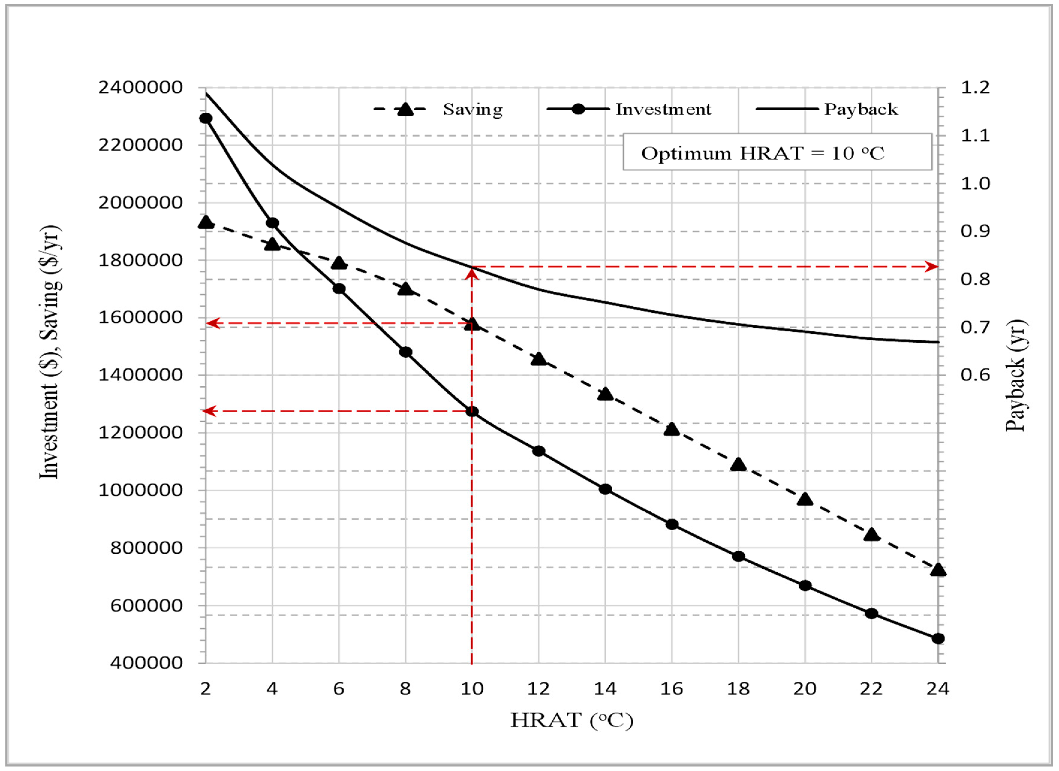
Figure 8 illustrates the economic profile of option 3. The saving and investment profiles of option 3 are similar to that of option 1. The investment cost profile in this option is lower while the saving profile is higher. As a result, the payback period is fastest with 0.82 yr at the optimum HRAT value. For the HEN case study, option 3 is considered as the best energy saving solution compared to option 1 and 2.
Also, the effect of reducing energy consumption in HEN on CO
2 emissions is analyzed. The profiles of CO
2 emission along the range of HRAT values for options 1, 2, and 3 are shown in
Figure 9. At optimum HRAT, option 3 shows the most CO
2 emission reduction of 17% compared with 15% and 8% for options 2 and 1, respectively. Therefore, option 3 is considered the best environmental option where the annual CO
2 emission from the HEN furnace heater has dropped from 25,190 kg/hr to 20,909 kg/hr at the optimum HRAT of 10 °C.
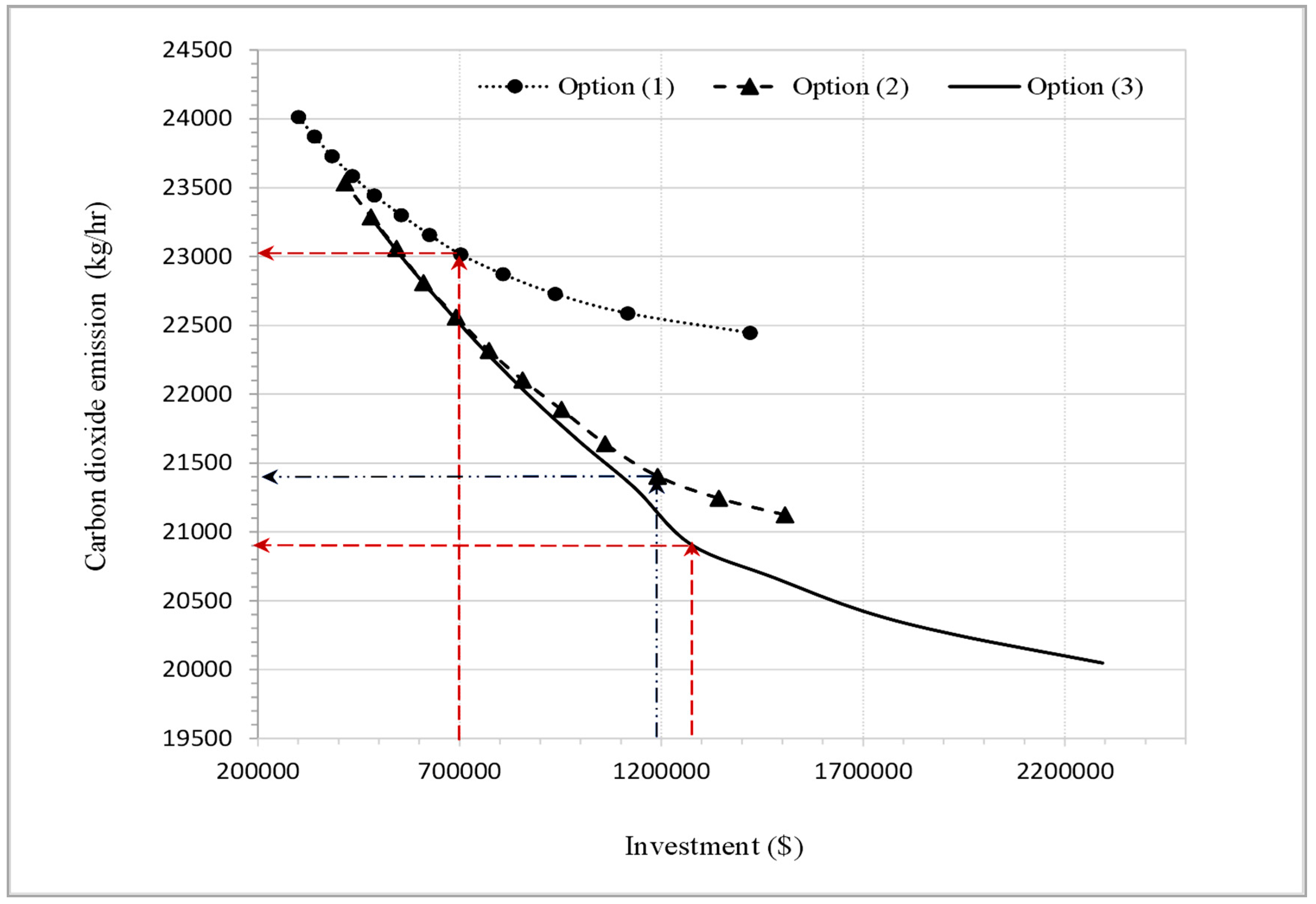
The profiles of CO
2 emission mass flow rate (kg/hr) concerning investment cost for options 1, 2, and 3 are shown in
Figure 10. Although option 3 shows a higher investment cost around
$1.3 M, it gives the lowest annual CO
2 emissions of 20,900 kg/hr at optimum HRAT of 10 °C.
5. Conclusions
Heat recovery enhancement is conducted using an approach based on mathematical laws of combination to generate several options of solutions. The present utility paths in the heat exchanger network have combined to successively shift heat load from heaters and coolers to the network exchangers. The heat-shifting process is performed for different values of heat recovery approach temperature while considering the pressure drop in HEN devices. From cost targeting analysis, the best option is selected based on the optimum heat recovery approach temperature. Then, an economic analysis has been performed for the options based on energy saving, investment, and payback period at the optimum heat recovery approach temperature. Finally, CO
2 emission has been evaluated concerning the heat recovery approach temperature and investment. Compared to a previous work done by Osman et al. [
24], who introduced paths combination for HEN retrofit at a fixed, the current study considered a wide range of temperature driving force using the cost targeting of Pinch Technology. Moreover, the present study analyses the impact of energy saving on the emission of CO
2 compared to those using paths combination while ignoring the environmental impact such as Awad [
14] and Abdelgadir [
15].
The real contribution of this study is:
Merging path combination approach with cost targeting of Pinch Technology to obtain high optimized solutions for energy saving in an existing heat exchanger network and reducing the emission of CO2.
The obtained energy saving solutions are considered as low-hanging fruit results where only minor retrofit is considered without topology changes to the network.
The approach adopted for this study is following the concept of Pinch Technology, and it is applied only for simple heat exchanger network such as preheat train unit. Systems that are more complicated can be investigated using the same approach under both Pinch Technology and mathematical programming to generate a hybrid-automated plan.


