1. Introduction
Ceramic-based membrane separation is widely accepted as a clean and cost-effective way to produce high purity oxygen from air [
1,
2,
3,
4,
5]. Additionally, these membranes can be integrated in reactors for partial oxidations, making these membrane reactors more efficient in terms of operational expenditures (OPEX) and capital expenditures (CAPEX). Since the first introduction of the mixed conducting ceramic oxides concept as a base for oxygen transport membranes by Cales and Baumard [
6,
7], considerable efforts have been invested to increase the oxygen conductivity and long-term stability of these membranes. The bulk-diffusion-based oxygen permeability through the membranes could be described by Wagner Equation [
8]:
where
jO2 is the oxygen permeation flux,
F is the Faraday constant,
R is the gas constant,
L is the membrane thickness,
P’’
O2 and
P’
O2 are the low and high oxygen partial pressure and σ
el and σ
ion are partial electronic and ionic conductivity, respectively. Accordingly, the oxygen permeability could be improved by increasing the partial pressure difference across the membrane, improving the operating temperature, choosing material with high conductivity or reducing the membrane thickness. As a simple way to achieve high oxygen fluxes, thin-film membranes are preferred for separation processes. Since a reduced membrane thickness is accompanied with lower mechanical stability, the thin-film membrane layers were usually coated onto porous supports resulting in asymmetric membrane structures [
9,
10,
11,
12,
13,
14,
15]. The support is a key component for the asymmetric membranes, which should provide sufficient mechanical stability, smooth surface for the deposition of thin dense membrane layers and good porosity to circumvent additional mass transfer resistances for oxygen transport.
Selection of proper materials for the support and selective layers is of great importance for the formation of asymmetric membranes with high performance. Permeability of the oxygen selective oxides, material cost, chemical and mechanical stabilities, as well as the compatibility of different layers are the main factors that should be taken into consideration during the material selection. Ce
0.9Gd
0.1O
1.95-δ (CGO) is a fluorite material with high oxygen ionic conductivity and it shows good long term stability under both reducing and oxidizing atmospheres, which makes it an attractive membrane layer material for operation under harsh conditions [
16]. To form gas-tight membranes the porous supports and the selective layers should exhibit identical shrinkage behaviour during the sintering process; for this reason most of the reports on multilayer membranes are dedicated to the fabrication of different layers with similar materials [
9,
10,
12,
13]. However, the membrane preparation could be more cost-effective if low-price alternatives are found for the supports of the membranes. MgO is a candidate because of its good mechanical and chemical stability and lower cost compared with most of the oxygen selective oxides used for the fabrication of the functional layers. Moreover, due to the similar thermal expansion coefficient between MgO (13.9·10
−6 °C
-1) and Ce
0.9Gd
0.1O
1.95−
δ (CGO, 12.7·10
−6 °C
−1) [
17,
18], MgO is preferred for the porous substrate when CGO based compounds are employed as the membrane layer material. Ramachandran et al. [
16] prepared a tubular MgO support by thermoplastic extrusion and CGO-based layers were deposited onto the support with a repeated dip-coating method. Ovtar et al. [
19] also applied the combined extrusion and dip-coating process for fabricating a tubular MgO supported CGO-La
0.6Sr
0.4FeO
3−
δ (LSF) dual phase membrane.
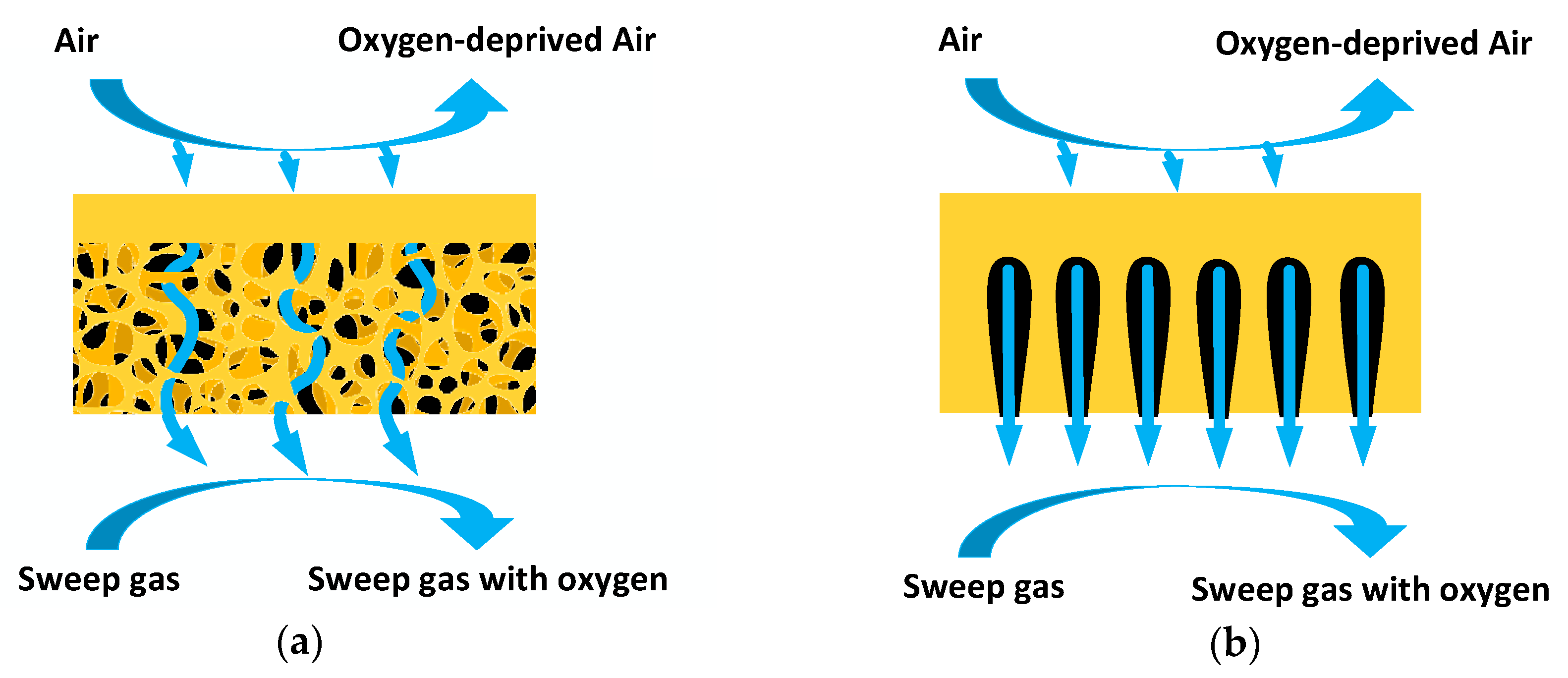
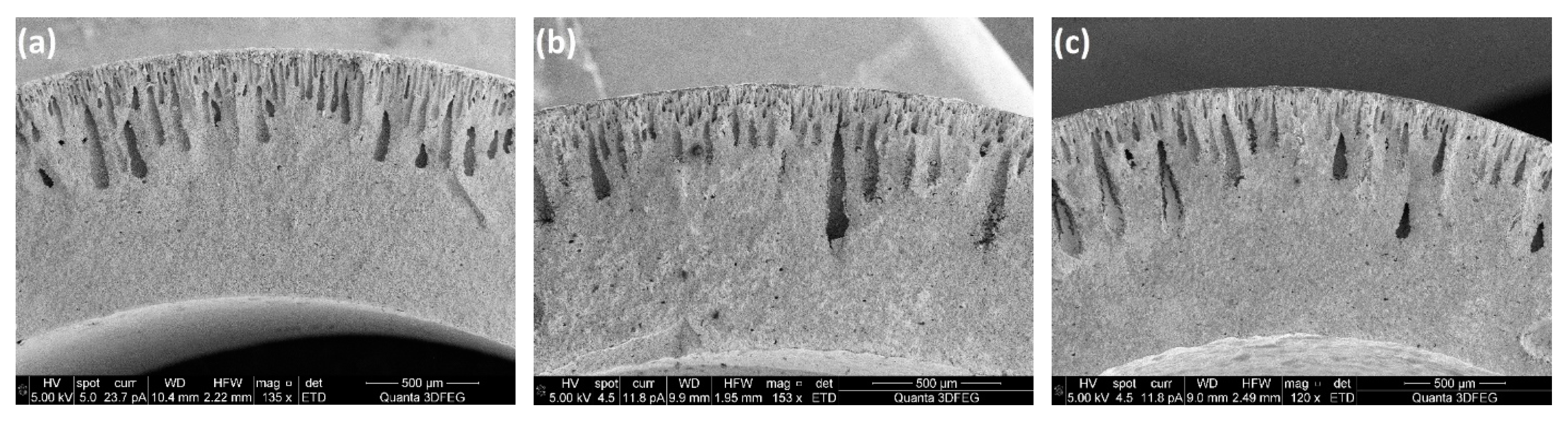
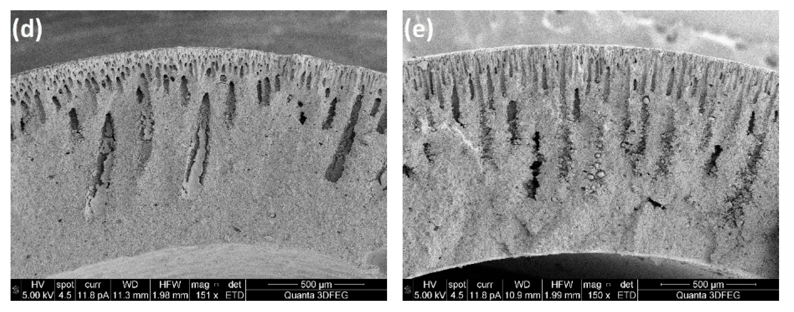
Thermoplastic extrusion is frequently used to produce tubular substrates of asymmetric membranes. Pores in the support tubes are formed by burning of the sacrificial phases, which are added to the paste prepared before the extrusion process. The resulting support tubes usually show a sponge-like microstructure. Although compared with the single-layer membranes, improved oxygen permeability has been achieved by coating thin-film membrane layers on to porous supports, the highly tortuous channels in the sponge-like support layer (
Figure 1a) still result in mass transfer resistances that reduce the oxygen flux. For further decreasing the gas transfer resistance, novel fabrication methods need to be developed. Phase inversion is a promising and low-cost method for preparation of membrane substrates showing low tortuosity. In this process, no pore formers need to be introduced into the ceramic paste. After casted into desired shapes, the ceramic pastes should be submerged into water to perform the phase inversion process. Instead of connected pores, finger like channels are formed because of the solvent replacement with water. The channels provide comparatively short path for gas transfer through the membrane support, which is shown in
Figure 1b. He et al. [
20] fabricated a Zr
0.84Y
0.16O
1.92 (YSZ)-La
0.8Sr
0.2MnO
3−
δ (LSM) asymmetric membrane with phase inversion process, which shows improved oxygen permeability than the one with a sponge-like substrate prepared by a sequential two-step tape casting method. The phase inversion method is mostly applied for fabricating asymmetric membranes with hollow fibre [
3,
4,
21,
22,
23] or planar disc configurations [
20,
24,
25,
26], while its application to the manufacture of tubular membranes is quite limited. A porous alumina support tube was successfully prepared by Zhu et al. [
27] with a novel phase inversion casting process but the resulting support tubes mainly showed sponge-like microstructure. Length of the channels in the tubular supports still need further improvement.
The formation of uniformly distributed channels of enough length in tubular membrane supports is more challenging than inside the hollow fibres or planar discs, because long micro-channels usually favour low viscosity of the slurries, while a too low slurry viscosity would bring difficulties in shaping the slurry into the tubular form. Optimization of the processing conditions in the phase-inversion-based preparation process to increase the microstructure of the support tubes is thus an area of great interest. In this work, the low cost phase inversion casting process designed by Zhu et al. [
27] is applied to fabricate MgO and MgO-CGO dual-phase support tubes. CGO layers were coated onto the substrates with dip-coating method. The effect of ceramic and polymer concentrations, particle size of the ceramic powders and the introduction of ethanol inside the casting slurries on the micro-channel size and tube shrinkage speed during sintering process were investigated to obtain MgO-CGO supports with a low mass transfer resistance and to achieve compatible shrinkage behaviour of the membrane layers and supports.
2. Materials and Methods
2.1. Materials
MgO powders purchased from VWR were used as the support tube material. Polyvinylpyrrolidone (PVP, Sigma-Aldrich, Missouri, USA), polyethersulfone (PES, Veradel 3000P, Solvay Advanced Polymers, Brussels, Belgium) and 1-methyl-2-pyrrolidone (NMP, 99.5%, Sigma-Aldrich, Missouri, USA) were dispersant, polymer and solvent, respectively, for the preparation of the tube-casting slurries. CGO powders supplied from Ningbo Sofcman Energy were used as the second phase in the support tube, after milling for 1 h in a planetary ball mill (Pulverisette 6, Fritsch, Idar-Oberstein, Germany). The influence of particle surface area on the channel growth was studied by applying two other kinds of CGO powders provided by Solvay and Marion Technologies, respectively, which were also ball milled for 1 h before adding them into the slurries.
The milled CGO powders from Ningbo Sofcman Energy were used for the membrane layer fabrication. PVP and PVB purchased from Sigma-Aldrich were used as the dispersant and binder in the suspensions for the dip-coating process, while ethanol (absolute, VWR, Pennsylvania, USA) was employed as the solvent.
2.2. Phase Inversion Casting for Support Tube Preparation
Phase inversion casting is a slurry-based method. Polymer and ceramic concentrations in the slurries are key factors that may influence the microstructure and performance of the support tubes. For preparing the slurries, first, PES and PVP were fully dissolved into NMP by mixing for 20 min using a planetary centrifugal mixer (ARE-250, Thinky, Tokyo, Japan) to form polymer solutions. The rotational speed of the mixer was set at 1850 rpm. MgO and CGO powders (or only MgO powders) were added successively into the solutions and mixed again for 30 min, which resulted in homogeneous slurries. Bubbles inside the slurries may influence mechanical strength and surface smoothness of the support tubes, so de-foaming procedures were applied using a rotational speed of 1850 rpm for 15 min after mixing the slurries in the same planetary centrifugal mixer. The PVP concentration (weight ratio of PVP over PVP+NMP) was fixed at 3.2 wt%, while the ceramic loadings (the weight ratio of CGO+MgO to CGO+MgO+NMP) were varied from 43 wt% to 60 wt% and a range of polymer concentrations (weight ratio of PES to PES+NMP) from 11 wt% to 25 wt% was selected to investigate their influence on the microstructure and shrinkage of the support tubes.
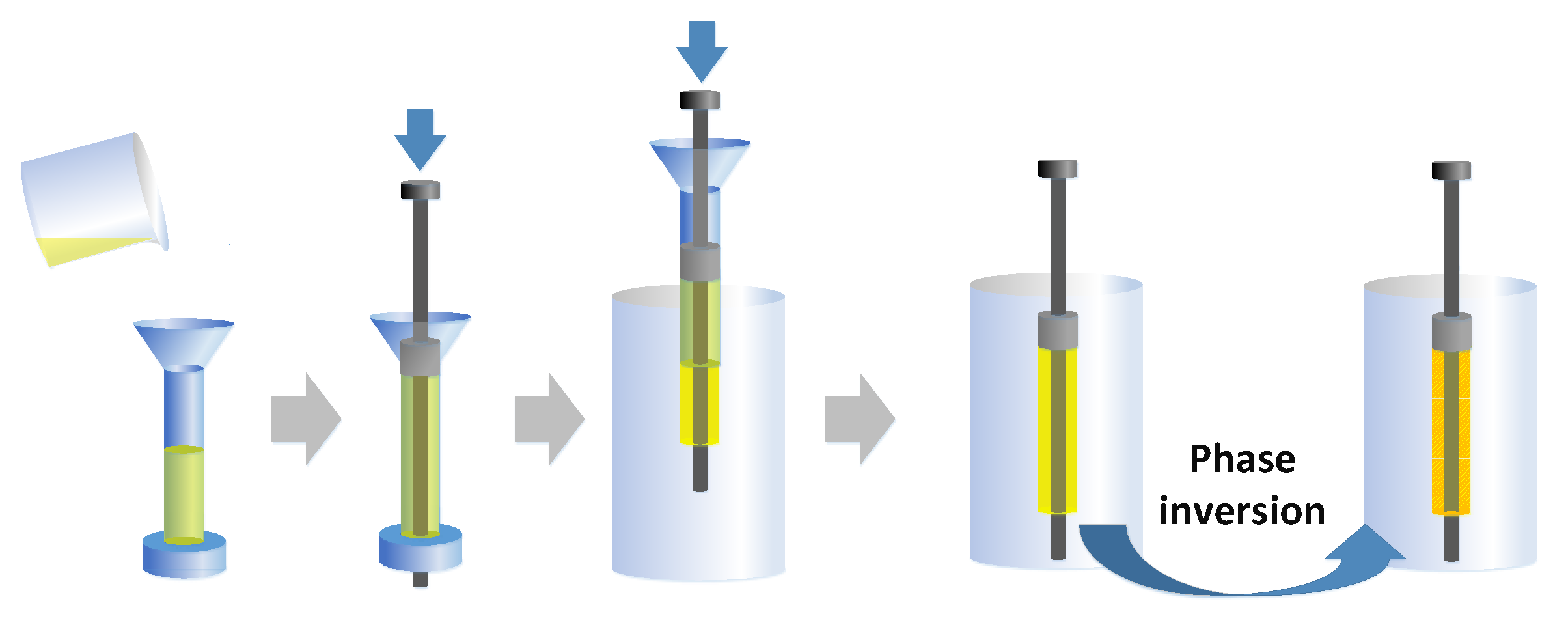
The phase-inversion casting process employed for the preparation of the micro-channelled support tubes is schematically depicted in
Figure 2. The simple casting device used for this process is a cylindrical mould with one side connected to a screw cap. An appropriate amount of the de-foamed slurry was used in the mould through the bell mouth and pushed inside the device with a piston for driving air out. The cap of the device was then taken off before placing it on top of water. Then the slurry was pushed out into water with the piston at a controlled speed. The phase inversion process started at the moment the slurry entered water. The slurry was kept inside water for 12 h at a temperature of 20 °C. Solidified green tubular supports were thus obtained in the water bath. Afterward, the green tube was taken off from the piston and dried at room temperature for 2 days before deposition of the membrane layer, because wet surfaces of the porous supports would result in non-uniform membrane layer formation. Outer and inner diameters of the obtained green support tubes were ~12 mm and ~8 mm, respectively.
2.3. Fabrication of Membrane Layer
CGO membrane layers were coated onto the green tubular supports by a dip-coating method. Because the micro-channels grew from outside surface of the porous supports in the water bath, CGO membrane layers were coated inside, while the external surface of the tubes was covered with plastic films during the dip-coating process. Before the dip-coating process, an ethanol-based suspension with a concentration of 23.9 wt% CGO, 2.4 wt% PVP and 1.9 wt% PVB was prepared with the planetary centrifugal mixer. Similar as for the preparation of the casting slurries, PVP and PVB were firstly added into ethanol to make a solution and subsequently the CGO powders were mixed with the solution at a speed of 1850 rpm for 30 min. An automatic dip-coater was employed to dip-coat membrane layers onto the green support tubes. The thickness of the membranes could be precisely controlled by programming the dip-coating speed and times with the dip-coater. The tubes were coated three times to achieve desirable gas-tightness by increasing the thickness of the coating.
The sintering process is of great importance for the fabrication of asymmetric membranes. After drying at room temperature, the membrane layers were sintered together with the green support tubes at 1350 °C for 2 h to form ceramic membranes with good mechanical strength. A heating rate of 30 °C/h was employed to increase the oven temperature to 1350 °C. The low heating rate is required because of two reasons. Firstly, uneven heating could break the ceramic supports and lower heating rate provides enough time for each part of the tubes to reach a uniform temperature. Besides, faster heating rate could result in a larger difference in strain rate between the membrane layers and the support tubes, which would cause cracks on the membrane layers. After sintering, the samples were cooled down inside the oven with a speed of 60 °C/h.
2.4. Analysis of the Membranes
The microstructure of the tubular asymmetric membranes was observed and compared with scanning electron microscopy (SEM, Quanta 3D FEG, Oregon, USA) operating in the secondary-electron mode at an excitation voltage of 5 kV. Before the SEM study, membrane samples were attached to the metallic SEM stages with graphite tapes and gold was sputtered on the membranes using a high-resolution sputter coater (Emitech K575X Peltier-cooled, Quorum Technologies, East Sussex, England), at the constant sputtering current of 65 mA for 30 s, with the purpose of preventing beam damage and allowing charge dissipation on the samples during the SEM study. The element distribution of the CGO-MgO dual-phase supported CGO membrane was obtained using the EDX mapping of a desktop SEM (Phenom ProX, Eindhoven, The Netherlands) at the voltage of 15 kV. A pixel time of 100ms was selected while the map resolution was set at 128×128 pixels. The specific surface area of the ceramic powders was measured with BET nitrogen adsorption isotherm (TriStar II, Micromeritics, Georgia, USA). The slurry viscosity was determined with a rheometer (Physica MCR 301, Anton Paar, Graz, Austria). Nitrogen permeation measurements were conducted to test the mass transfer resistance of the support tubes. The setup for the permeability test mainly consisted of a chamber, a gas supply unit and a film flow meter (STEC SF, Horiba, Kyoto, Japan). The membranes were introduced into the chamber after being sealed with some metal tubes. Nitrogen was fed into the membranes through the tubes using a mass flow controller and the nitrogen permeated through the porous supports was collected at the shell side and sent to the flow meter for the flow rate measurement. In this work, we are only interested in the gas tightness of the membranes, thus no perm-selectivities and oxygen fluxes have been measured. The chemical stability of the dual-phase supported membrane was tested in pure CO2 atmosphere at 850 °C for 500 min. The flowrate of CO2 was set at 480 mL/min. For better contact of the membrane material with the feeding gas, the membrane was crashed into small pieces. The XRD patterns of the samples before and after the stability test were obtained using an X-ray diffractometer (Rigaku MiniFlex, Tokyo, Japan).
3. Results and Discussion
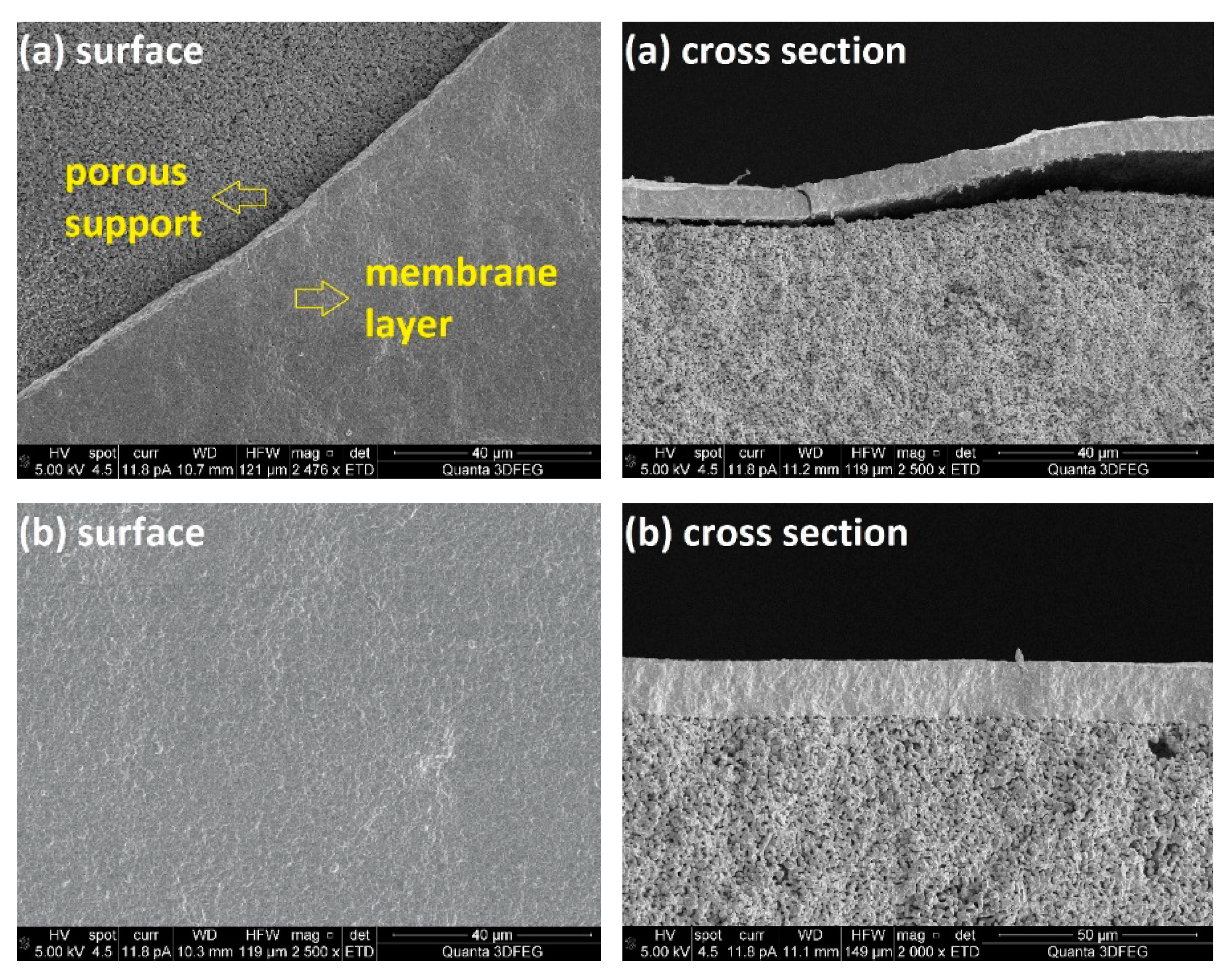
SEM images of the prepared porous MgO-supported CGO membrane are presented in
Figure 3a. Partial delamination of the sintered CGO layer from the support tube can be observed from surface and cross section of the asymmetric membrane. This result was reproducible for several membranes and is mainly caused by differences in shrinkage behaviour of the membrane support and the selective layer. To increase attachment of the membrane layer onto the substrate and to improve gas tightness of the supported membrane, a mixture of 60 wt% MgO and 40 wt% CGO powders was used instead of the pure MgO powders for the preparation of the casting slurries for phase inversion. A crack-free CGO membrane layer with a thickness of ~20 µm was obtained on the dual-phase support and strong attachment was achieved between the two layers (
Figure 3b). This result was again quite reproducible for several membranes. However, the figure also shows a very homogeneous membrane support, which would result in pronounced mass transfer resistances. Thus, the next step is to create a porous structure in the supports before coating the selective layers. The composition of the casting slurry was varied to investigate the effect on the microstructure and performance of the dual-phase ceramic support.
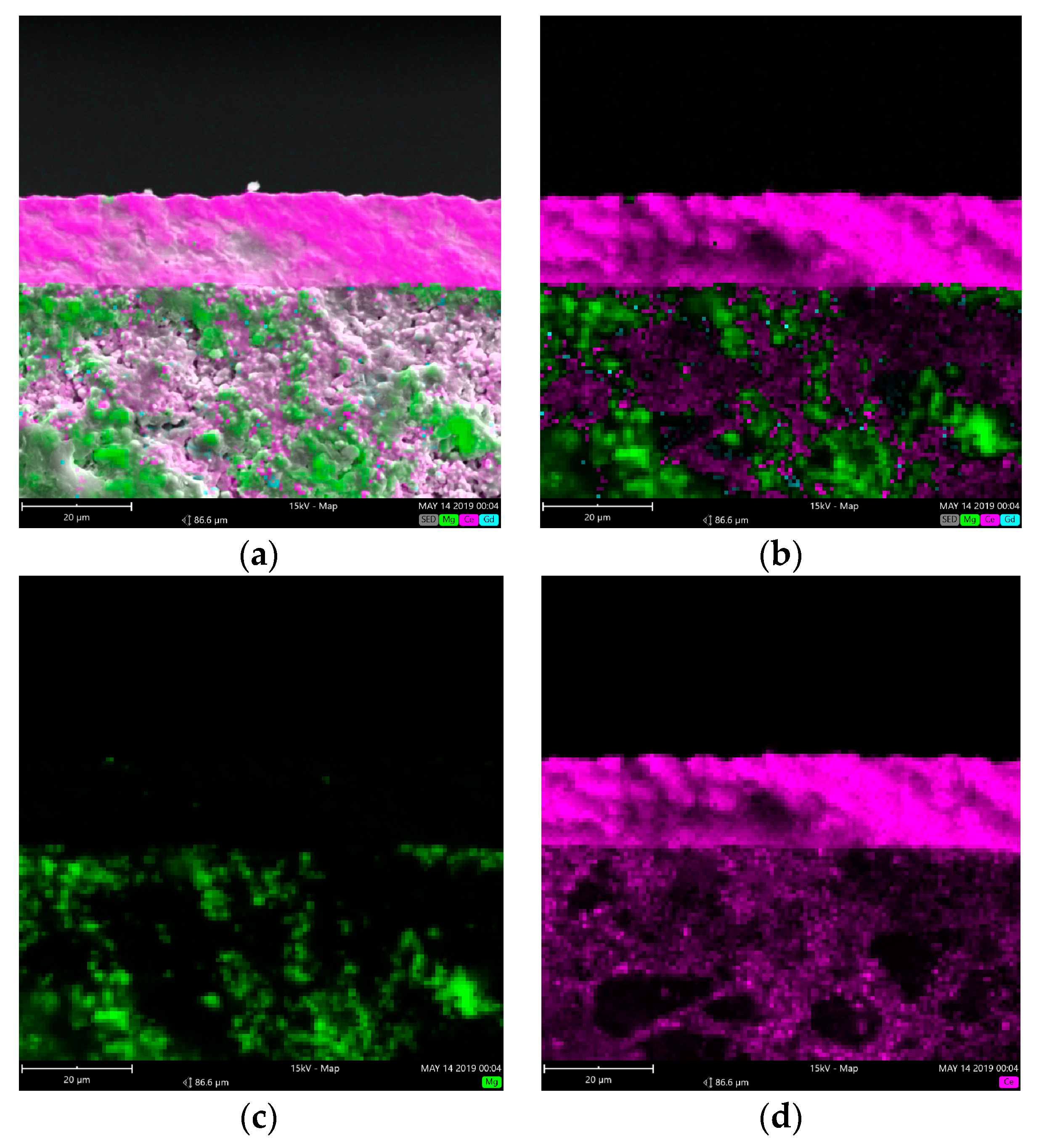
The element distribution on the cross section of the CGO-MgO dual-phase supported membrane is presented in
Figure 4. It can be observed that in the membrane support both the element of Ce and Mg were detected, while only Ce was found in the membrane layer and the distribution of Ce in the membrane layer is denser than that in the support, suggesting that the CGO concentration is higher in the membrane layer than inside the support.
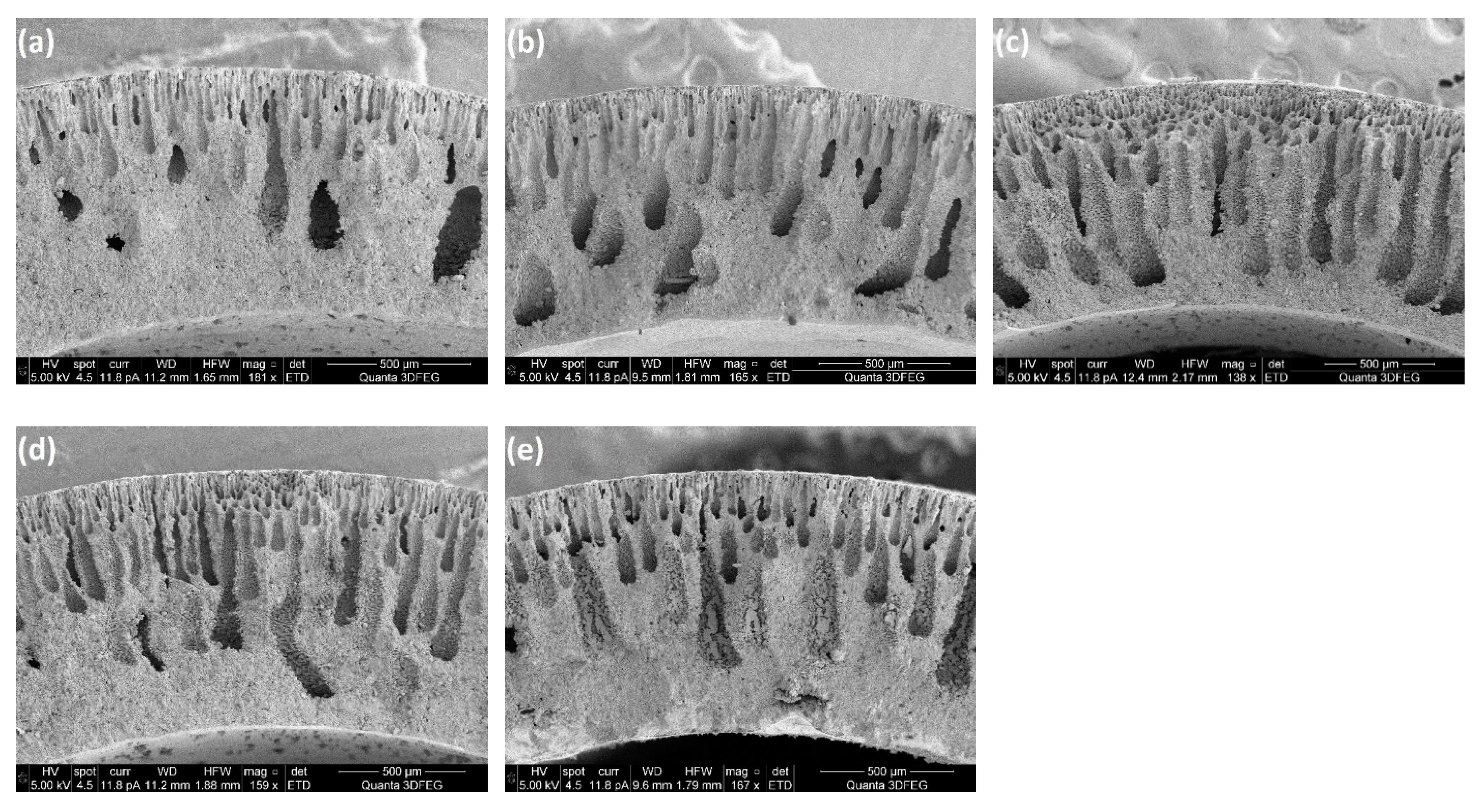
3.1. Influence of Ceramic Loading
The polymer concentration in the solution is the key factor that can influence the channel length in the polymer membranes by affecting the resistance for water transfer into the solution. In addition to the polymer concentration, also the ceramic loading in the slurry is an important parameter that can influence the length of the micro-channels in the ceramic tubes. Moreover, the ceramic concentration also influences the shrinkage behaviour of the support tubes during the sintering process and thereby the adherence of the membrane layers on the supports. When the ceramic loading was lower than 43 wt%, the slurry exhibited inadequate plasticity to maintain the tubular shape during the casting process, while a ceramic loading above 60 wt% caused cracks on the sintered support tube because the chosen PES concentration in the solution was insufficient to handle this ceramic loading. According to this, the ceramic loading was varied from 43 wt% to 60 wt% to investigate its influence on quality of CGO coatings and growth of the micro-channels, while the polymer concentration was fixed at 18 wt%. For each 20 g of NMP, 15 g, 17.5 g, 20 g, 25 g and 30 g PES were added, respectively, in the polymer solution, resulting in ceramic loadings of 43 wt%, 47 wt%, 50 wt% 56 wt% and 60 wt%. Bigger step was applied for the change of ceramic loading from 50 wt% to 60 wt%, because the ceramic content in the slurry shows smaller influence on the slurry viscosity and microstructure of the support at high ceramic loading than at the range from 43 wt% to 50 wt%.
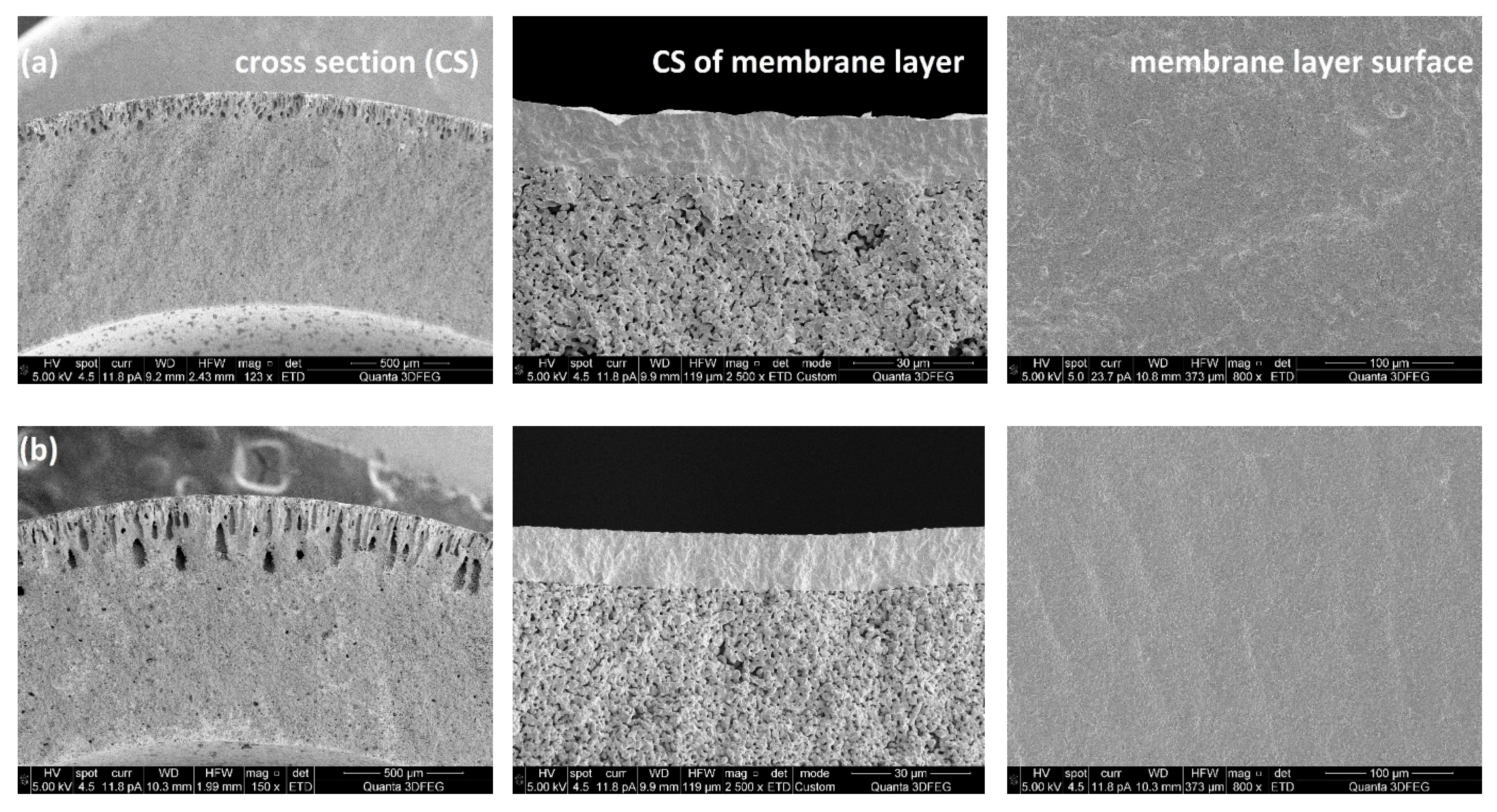
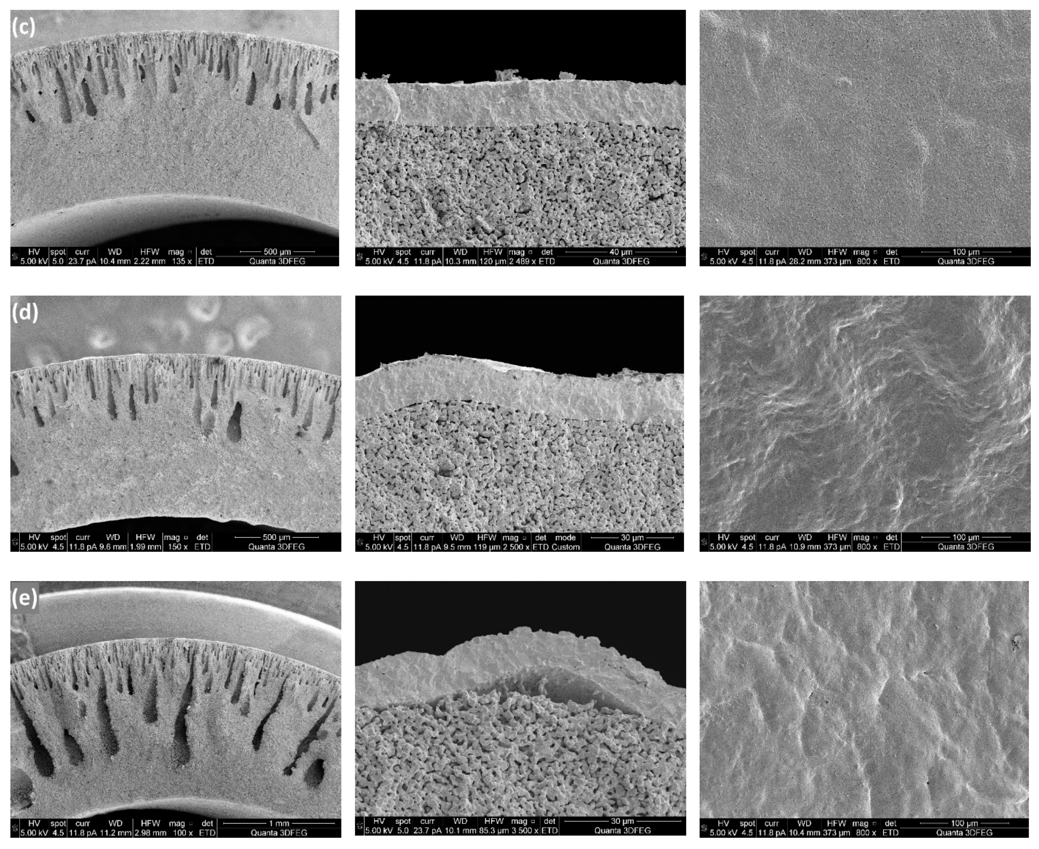
Figure 5 shows SEM images of porous supports prepared at different ceramic loadings and the membrane layers coated on top. It can be observed from cross sections of the membrane supports, that all the support tubes have two layers: one layer with finger-like pores (channels) which provides low mass transfer resistance and the other one with sponge-like microstructure. It is also clear that the ceramic loading in the preparation recipe has a large effect on the thickness of the layer with channels. Sufficiently long and very homogeneous channels were obtained in the support tube, when the ceramic loading was 43 wt%, while the “pore-size” decreased when adding ceramic powders to the casting slurries, which could be attributed to the improved resistance for the channel growth because of the increased viscosity of the slurries (
Figure 6). It should be noted that the slurry with a ceramic concentration of 43 wt% showed a rather high fluidity, which means a high pushing speed was required to keep a tubular shape of the slurry when introducing the piston into water.
Large shrinkages of the porous support tubes were observed after the sintering, because of burning of the polymers and sintering of the ceramic particles. The ceramic loading had a great influence on the tube shrinkage. In this work the shrinkage of a support tube was quantified by measuring the tube length before and after the sintering process.
Table 1 shows the effect of the ceramic loading in the casting slurry on the shrinkage of the porous supports. The results can be explained by the decrease in the weight ratio of polymers to ceramic powders, where the smaller shrinkage of the support is attributed to reduced polymer burning during the sintering process. Dense membrane layers can be achieved only when the porous supports and membrane layers exhibit uniform shrinkage behaviours. From SEM images of the surfaces of the membrane layers (
Figure 5), it is clear that with a ceramic loading of 60 wt%, several cracks were formed on the membrane layer which indicates that the shrinkage of the membrane was faster than that of the support tube. However, when the ceramic loading was below 47 wt%, the MgO-CGO supports shrank faster than the layers, which caused the membrane layers to be corrugated and thus also fragile. Accordingly, in terms of the shrinkage behaviour compatibility between the membranes and supports, ceramic loadings between 50 wt% and 56 wt% (polymer/ceramic ratios between 0.225 and 0.180) were the best choice for preparing the casting slurries, which resulted in selective layers with no connected pores or cracks but some closed pores and surface defects with a pore size of 0.2-1µm. No obvious effect of the closed pores and surface defects was observed on the gas-tightness of the selective layers.
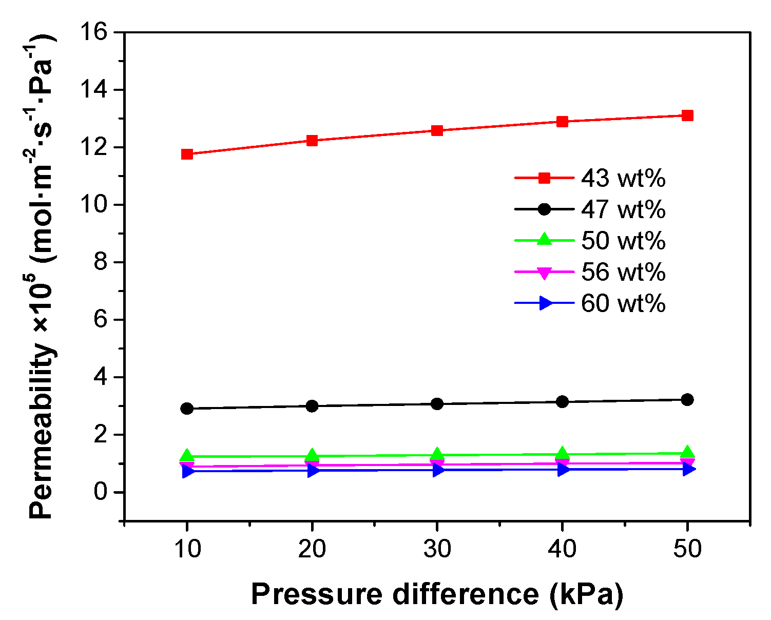
Nitrogen permeation measurements were conducted for the porous supports fabricated with different ceramic loadings. Pressure differences (ΔP) from 10 kPa to 50 kPa were applied across the support tubes and the gas permeation through the supports are plotted as a function of ΔP in
Figure 7. A small increase in the nitrogen permeability with ΔP was observed for all the test membranes, because of viscous flow through the small pores [
28].
Figure 7 also reveals that the effect of reducing ceramic loading inside the slurry is an increase in gas permeability through the support tubes. Especially when the ceramic loading was decreased from 47 wt% to 43 wt%, a very significant increase in the gas permeation flux was observed, which could be attributed to decrease of the tortuosity of the micro-channels.
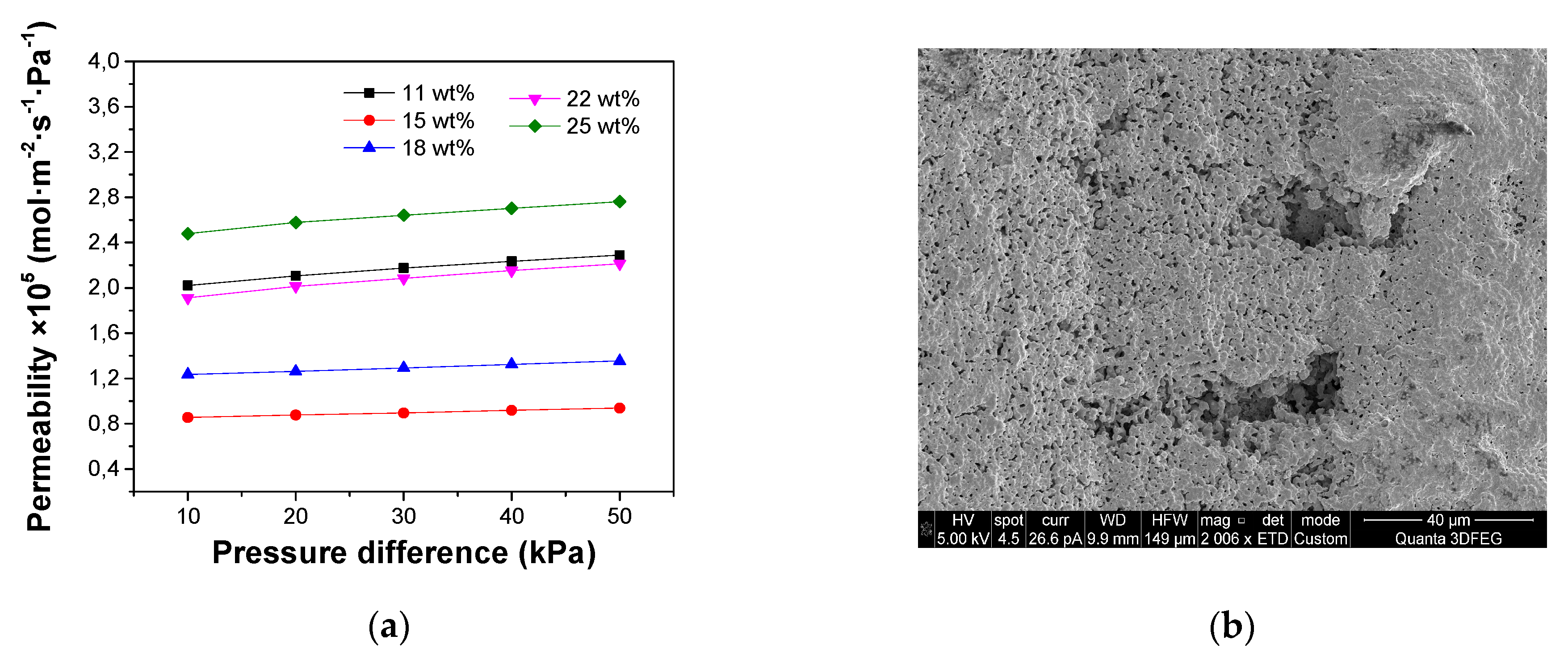
3.2. Influence of Polymer Concentration
A high water-solvent exchange rate promotes the growth of micro-channels during the phase inversion. For polymer membranes, the number and size of finger-like channels formed in the water bath tend to decrease when the PES concentration in the solution was increased, which indicates that a high polymer concentration would frustrate the conversion between water and solvent [
29]. Based on the research of polymer membranes, in this work the effect of the PES concentration on the channel growth in the ceramic membrane supports was investigated. As with excessive ceramic loadings inside the slurries, when the polymer concentrations were below 11 wt%, the supports generally broke during the sintering process, because the polymer was insufficient to handle the ceramic powders. As a result, a range of polymer concentrations from 11 wt% to 25 wt% was selected to investigate its influence on the microstructure of the supports and membrane layers while the ceramic loading was kept at 50 wt%. For each 20 g of NMP, 2.5 g, 3.5 g, 4.5 g, 5.5 g and 6.5 g PES was added, respectively, in the polymer solution.
As shown in
Figure 8, for the chosen ceramic loading, the channel length increases when increasing the polymer concentration in the recipe, which is opposite to the result obtained for polymer membranes. Adding ceramic powders to the polymer solutions caused a large increase in the resistance for water exchange with the solvent, while PES in the suspension performed as a surfactant for the ceramic powders by adsorbing on the surface of the particles [
30]. Aggregation of the ceramic particles could be avoided due to the presence of the polymers, so increased PES contents resulted in a reduced resistance for channel growth. In addition, the finger-like pores were found to disappear gradually with increasing the phase inversion time [
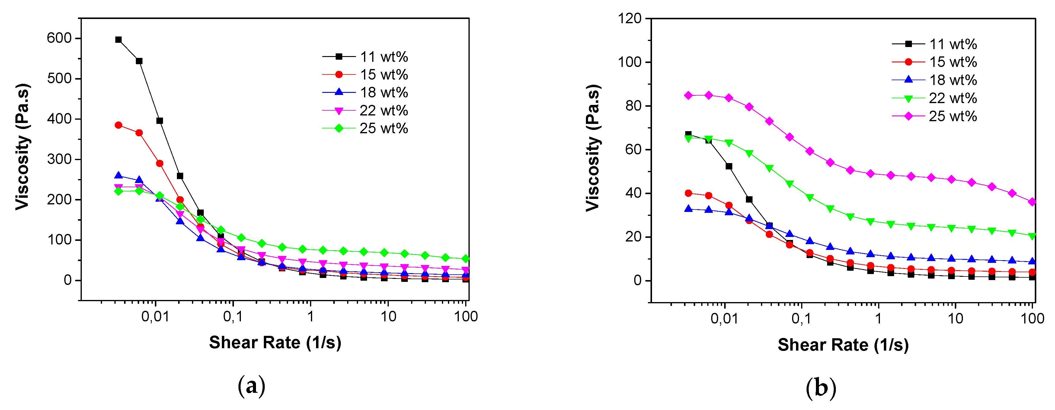
31] but a higher content of PES, which also performed as binder of the particles, would result in stronger walls of the channels. The rheological behaviour of the slurries with different PES concentrations at a fixed ceramic loading of 50 wt% is shown in
Figure 9a. It is evident that all the slurries exhibited shear thinning behaviour (viscosities decreased with increased shear rate) and this behaviour became more pronounced when the polymer concentration was decreased. As a result, at low shear rate the viscosities of the ceramic slurries decreased with increased PES concentrations, while at high shear rate the slurries with low PES concentrations were less viscous than the ones with more PES. The rheological behaviours in the zero-shear viscosity plateau region were consistent with the decrease of water transfer resistances when increasing the PES concentrations.
Table 2 presents how the shrinkages of the porous supports after the sintering process are affected by the polymer concentrations in the slurries. It is clear that increased polymer concentrations result in larger length shrinkages of the support tubes. During sintering, shrinkage of the ceramic substrate can be divided into two stages: the initial stage starts at relatively low temperature, which is caused by the release of the organic polymers, while the second and more significant shrinkage occurs at a much higher temperature due to sintering of the ceramic particles and the reduction of the residual porosity formed by the burning of the polymers. Increase of the polymer content in the green substrates caused larger initial shrinkages during release of the polymers and larger pore volumes, which also resulted in increased shrinkages during the second stage. Microstructures of membrane layers formed on substrates with different polymer concentrations are shown in
Figure 8. Good membrane layers were obtained with polymer concentrations between 15 wt% and 18 wt% (polymer/ceramic ratios between 0.175 and 0.225), which is because of the compatible shrinkage behaviour of the substrates and the inside films. No connected pores or cracks but some surface defects and closed pores with a pore size of 0.2-1µm were observed in these selective layers. However, these closed pores and surface defects did not show obvious effect on the gas-tightness of the selective layers. Detachment and cracks of the membrane were formed with a polymer concentration of 25 wt% in the casting slurry, because of over-shrinkage of the support tube.
Figure 10a shows the gas permeation as a function of ΔP for the support tubes prepared with different polymer concentrations, when ceramic loadings fixed at 50 wt%. The slurry with 25 wt% PES resulted in a porous support with the highest permeability and a declined permeation flux was observed when the polymer concentration was reduced to 15 wt%, which is attributed to the reduced channel length and the decreased porosity formed by burning of the polymers. However, decreasing the polymer concentration to 11 wt% did not further reduce the gas permeability, because some micro-cracks were formed on the support tubes (
Figure 10b), which could be expected from the insufficient polymer concentration for handling the ceramic loading.
To further examine the role of PES in the phase inversion process for ceramic support fabrication, another group of slurries with a ceramic loading of 43 wt% was prepared and the polymer concentration was increased from 11 wt% to 25 wt% to investigate the growth of micro-channels inside the tubular supports. From the SEM images of the support tube cross sections (
Figure 11), it is observed that the longest and most homogeneous channels were achieved when the polymer concentration was 18 wt%, which means that this slurry provided the lowest resistance for water-solvent exchange. Below the polymer concentration of 18 wt%, the channel length increased with the PES content, which could be attributed to the dispersing effect of PES. However, a reduced channel size was observed when more PES was added into the slurry with polymer concentration of 18 wt% and this can be understood by considering that, when the surfaces of the particles were fully covered with polymer, excess polymer increases the resistance for phase inversion, as for the polymer membranes. Consistent results were also observed for the rheological behaviour of the slurries at the zero-shear viscosity plateau region (
Figure 9b), which means that the lowest viscosity of the slurries (lowest channel growth resistance) was obtained at the polymer concentration of 18 wt%. Dong et al. [
30] reported similar rheological behaviour for NiO/YSZ ceramic slurries by adjusting the dispersant concentration in the suspension. By comparing the results of these two groups of experiments with the ceramic loadings fixed at 50 wt% and 43 wt%, it is evident that an increased ceramic loading requires more polymer as surfactant to achieve sufficiently long channels in the ceramic supports because of the improved specific surface areas of the powders.
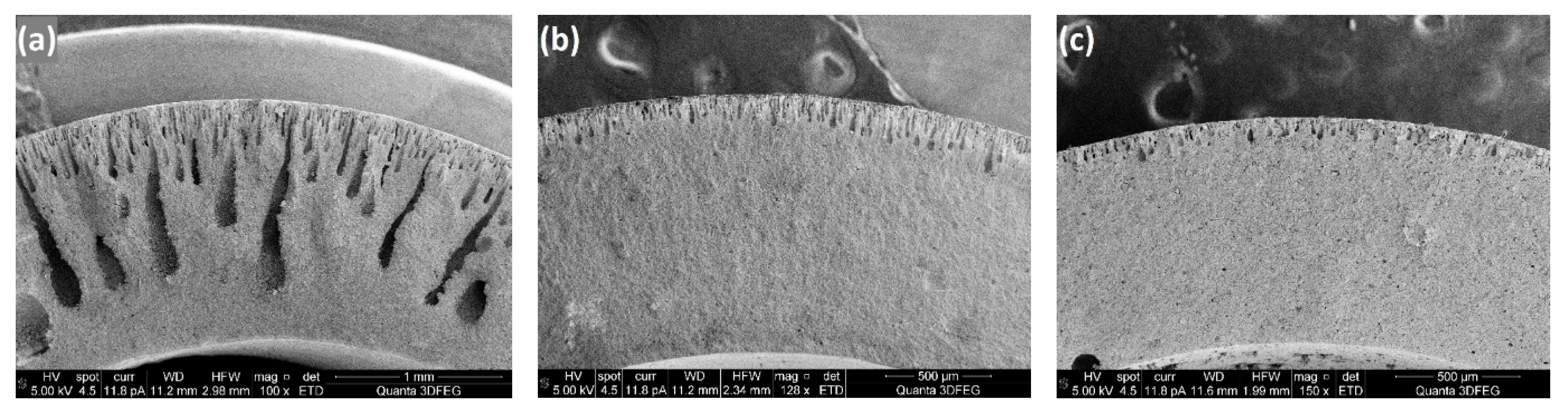
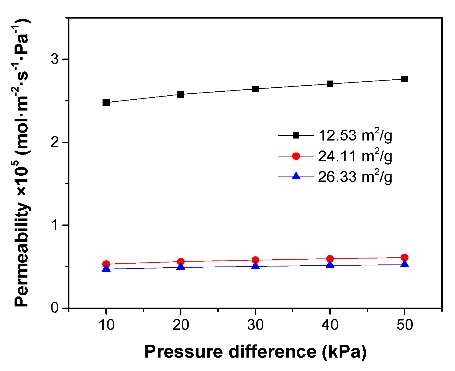
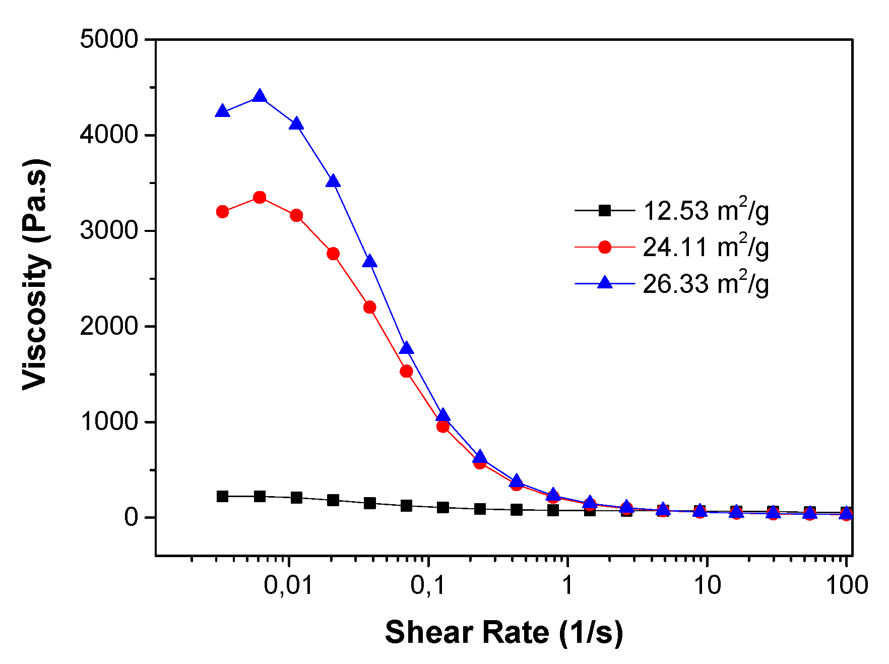
3.3. Influence of Particle Surface Area
Three kinds of ceramic powders with BET specific surface areas (SSA) of 12.53 m
2/g, 24.11 m
2/g and 26.33 m
2/g, respectively, were applied to the preparation of ceramic casting slurries for phase inversion. The PES concentration was fixed at 25 wt%, while the ceramic loading was 50 wt%. The microstructures of the support tubes fabricated with these three slurries are shown in
Figure 12. The channel length decreased significantly when the SSA of the ceramic particles was increased from 12.53 m
2/g to 24.11 m
2/g, leading to an abrupt decrease in the gas permeability through the porous support (
Figure 13). This result further confirms the surfactant role of PES by coating on the surface of the ceramic particles. Larger SSA of the powders requires more surfactant to reduce the resistance for the water-solvent conversion. Accordingly, for a specific polymer concentration, the slurry with the lower SSA might have a lower resistance for channel growth.
Figure 14 reports the effect of the ceramic powder SSA on the slurry viscosities. At low shear rate, the CGO powders with an SSA of 12.53 m
2/g resulted in a much lower slurry viscosity than the ones with an SSA of 24.11 m
2/g and 26.33 m
2/g.
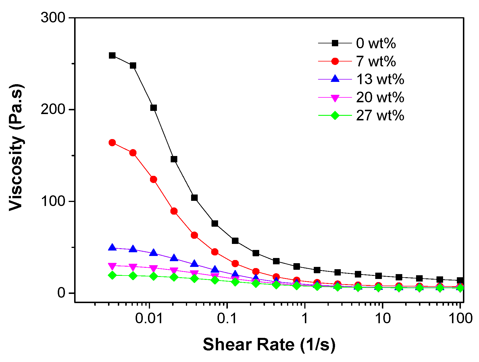
3.4. Addition of Ethanol to the Ceramic Slurry
Smolders et al. [
32] proposed a mechanism for the formation of macrovoids (channels), by attributing the occurrence of the channels inside polymer membranes to the instantaneous liquid-liquid demixing and the formation of membranes without channels to the delayed demixing. They also concluded that the low non-solvent (water) concentration in the diffusion front would cause delayed demixing, which would hinder growth of the channels, while adding a certain amount of water to the polymer solution could change delayed demixing to instantaneous demixing and increase the channel length.
In this work, also the effect of adding a non-solvent to the casting slurries on the microstructures of the ceramic membrane supports was also investigated. Ethanol was applied instead of water as the non-solvent addictive because of the low solubility of PES in water, which would cause precipitation of the PES before the phase inversion casting process when adding a small amount of water into the polymer solutions. Excess ethanol in the mixture would also cause precipitation of the polymers, which means that the amount of ethanol added to the solution should be precisely controlled. Various NMP-ethanol-PES-PVP solutions with ethanol contents (weight ratios of ethanol to ethanol+NMP) ranging from 0 wt% to 27 wt% were prepared. Precipitation of PES occurred at the surface of the polymer solution when ethanol was dripped into the mixture because of the lower density of ethanol compared to NMP. However, the solution tended to become pellucid after mixing for 5 min in the centrifugal mixer, when ethanol mixed thoroughly with the solution. Then, the ceramic powders were added into the solution to obtain the ceramic casting slurries. The PES concentration (weight ratio of PES to PES+ethanol+NMP) was fixed at 18 wt%, while the ceramic loading (weight ratio of ceramic powders to CGO+MgO+ethanol+NMP) was 50 wt% in this group of experiments.
From the cross sections of the obtained ceramic supports (
Figure 15), it can be observed that the length of the channels tended to increase when the ethanol contents were increased from 0 wt% to 27 wt%. Jin et al. [
31] employed the solubility difference parameter (|∆δ|) for the evaluation of the driving force to form finger-like channels. By applying liquids with different solubilities as the coagulants to adjust the driving force, they verified that the figure-like channels are easier to form when |∆δ| between NMP and the coagulant is improved. The solubility parameters for NMP, water and ethanol are 22.9, 47.9 and 26.0 respectively. In the channel growth front, the water concentration is lower (NMP concentration is higher) than at the initial interface between the slurry and water bath, which may result in a declined solubility of the coagulant and the resulting |∆δ| is insufficient for the formation of long enough channels. Since the solubility parameter of ethanol is higher than that of NMP, adding a certain amount of ethanol to the casting slurry can help increasing the solubility in the diffusion front and improve the driving force for channel growth. Moreover, in
Figure 16 it is shown that the slurry viscosity at the zero-shear viscosity plateau region declined when the ethanol concentration was increased. According to the former results, a decreased low shear rate viscosity would promote channel growth inside the ceramic membrane supports.
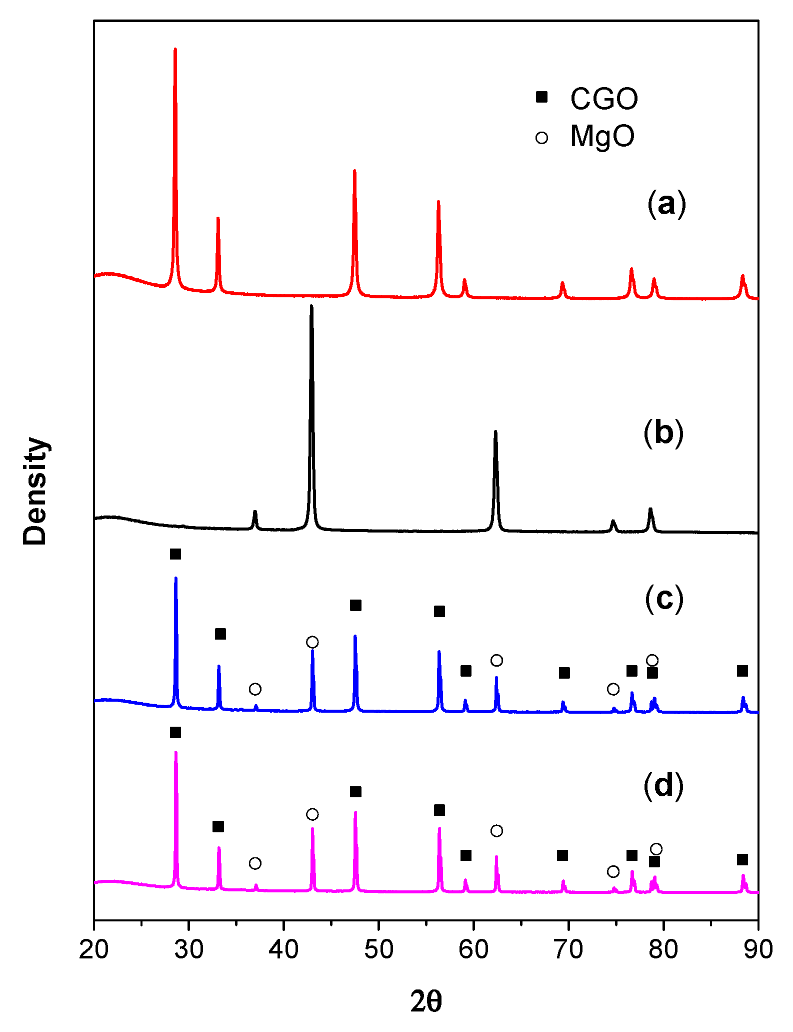
3.5. Chemical Stability of the Membrane
The XRD patterns of the dual-phase supported CGO membrane pieces before and after the chemical stability test in CO
2 atmosphere, together with the XRD patterns of MgO and CGO powders are presented in
Figure 17. It indicated that CGO and MgO remain unchanged in the CGO-MgO dual-phase material after the heat treatment during the membrane preparation process. Besides, it can also be observed that after the stability test, the membrane pieces completely kept their dual phases (CGO and MgO). No carbonate was formed. The chemical stability of the membrane in CO
2 atmosphere was confirmed to be good during the testing period (500 min).


