Communication

Analysis of the Excess Hydrocarbon Gases Output from Refinery Plants

by
Jerzy Szpalerski
1 and
Adam Smoliński
2,*
1
PKN ORLEN S.A., Chemików Str. 7, 09-411 Płock, Poland
2
Central Mining Institute, Plac Gwarków 1, 40-166 Katowice, Poland
*
Author to whom correspondence should be addressed.
Processes 2019, 7(5), 253; https://doi.org/10.3390/pr7050253
Submission received: 8 March 2019 / Revised: 21 April 2019 / Accepted: 25 April 2019 / Published: 1 May 2019
(This article belongs to the Special Issue Gas Capture Processes)

Abstract

:
The article presents the ideas of maximizing recovery of flare gases in the industrial plants processing hydrocarbons. The functioning of a flare stack and depressurization systems in a typical refinery plant is described, and the architecture of the depressurization systems and construction of the flares are shown in a simplified way. The proposal to recover the flare gases together with their output outside the industrial plant, in order to minimize impact on the environment (reduction of emissions) and to limit consumption of fossil fuels is presented. Contaminants that may be found in the depressurization systems are indicated. The idea presented in the article assumes the injection of an excess stream of gases into an existing natural gas pipelines system. A method of monitoring is proposed, aiming to eliminate introduction of undesirable harmful components into the systems.

1. Introduction

There are many technologies applied in processing of so widely understood charges [1,2,3,4,5] in the industrial plants dealing with crude oil or individual hydrocarbons processing. Typical production processes carried out in the refineries are: fractional distillation process, catalytic cracking process, gasoline reforming process, diesel/oil/hydro desulfurization, hydrocracking, gasoline isomerization, asphalt oxidation, and storage of raw materials, semi-finished products and finished products [1,2,3,4,5].
As a part of the refinery, many auxiliary processes are carried out, without which a modern refinery could not function, particularly the refinery in which extended are conversion processes that lead to greater destruction of the hydrocarbon chain. Among these processes, the following should first and foremost be distinguished [5,6,7]:
  • Hydrogen production;
  • Claus’s process;
  • Energy media production processes;
  • Wastewater treatment, production of circulating water; and
  • Hydrogen recovery processes.
Refineries produce engine fuels, lubricating oils, other commercial fluids, and some refinery products are used as raw materials for petrochemical processes. This is particularly important when the refinery plant is integrated with a petrochemical plant [8]. Among the petrochemical processes, above all should be mentioned [9,10,11,12] production of olefins, butadiene, aromatic hydrocarbons, cumene, or ethylene oxide.
These processes aim at obtaining products that comply with the relevant technical specifications (technical conditions, company standards, national standards, etc.). During almost every production process various types of by-products (gaseous, liquid) are formed. Great efforts are made to achieve a situation in which the by-products are utilized within the production plants. In the case of gas products, the aim is also to direct them to a further process. However, there is always a certain amount of gas products that for various reasons cannot be utilized. Some of these streams are directed to the flare stacks. These are not only streams coming from production but also streams from the preparation of entire production units to stop (e.g., repairs), from commissioning, and finally from the preparation of individual apparatus for repair, revisions provided for by law, system switching, etc.
It happens that industrial gas streams, directed to depressurization systems, are full-value products which should be used outside the plants as a fuel for energy combustion whether they cannot be used in the industrial plant at the moment.
The aim of this paper is to analyze the possibilities of maximizing recovery of the flare gases in the hydrocarbon processing plants.

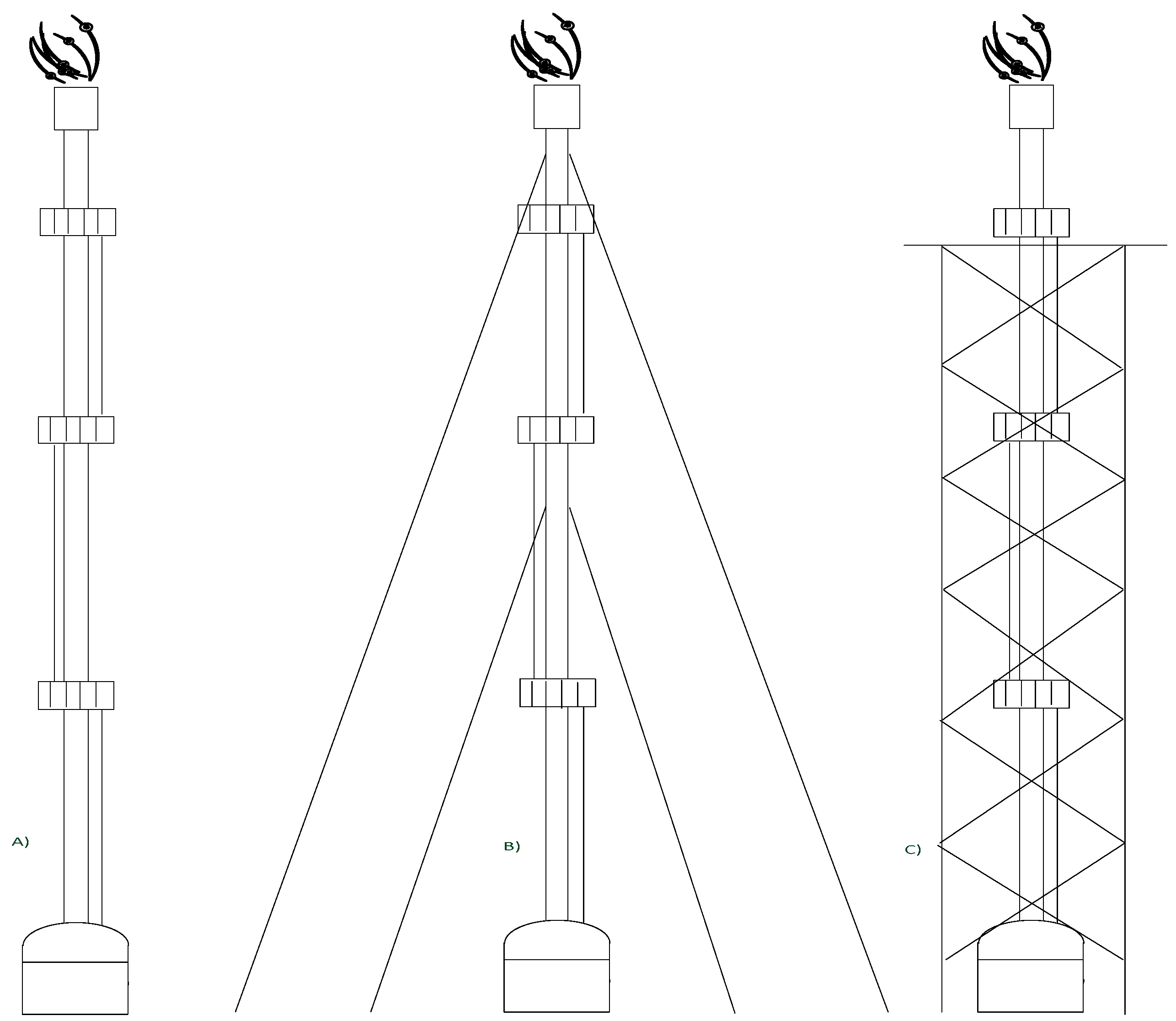
2. Flare Gases in the Industrial Plants

Some of the gas streams coming from various types of operations, carried out on production installations, are directed to the flare stacks. However, it is not possible to consider the flare stack as isolated from the entire depressurization system that is understood as a system of pipelines and collectors with assigned devices supplying the flare gases to the flare [13,14]. The flare stacks are applied and used most often in the crude oil and natural gas mining facilities, refineries, coke plants, chemical plants, and garbage dumps. The flare stack (utilization flare) is a device, usually in a shape of a stack, which burns the not utilized gas (generally), or which excess is impossible (or inexpedient) to be managed or stored at a given moment. Gas combustion in flares is mainly used in order to:
  • Protect the surrounding (locally) against the effects of uncontrolled migration of gas, e.g., against explosion, poisoning, and fetor;
  • Protect the environment by replacing emissions of more harmful gases by emission of less harmful fumes (e.g., acid gases—hydrogen sulfide, ammonia—occurring primarily as waste gases during the production process; directing acid gases to the flares happens extremely rarely).
In the most commonly used open flares, gas combustion takes place at their outlet [14]. In the closed flares, gas combustion takes place in the inlet (lower) part of the flare. In view of construction, it is usually a stack supported by a lattice tower supporting system with a triangle or a square base. What distinguishes it from a typical stack it is the use of a different technological solution. In the typical solutions, the stack serves for removal of waste gases that remain after the process, e.g., combustion. In case of the flare stack, it is used to transport the waste gases coming from the technological processes that will be burnt with open fire at its outlet, by the burner installed there. For this reason, the entire technological system of the flare consists of a knockout drum with liquid seal drum located at the base, constituting the beginning of the stack pipe, which can be a self-supporting element, self-supporting with guy-ropes or can be supported on the tower lattice structure. In the upper part of the stack pipe there is a head part with a molecular seal, protecting against the penetration of fire inside the stack and equipped with a main burner in which the waste gases are burnt. The discharge gases ignite from the "pilot" burner, on which a burning flame is continuously maintained. The flares are devices classified to the first class of reliability. Properly functioning discharge and flare systems guarantee safe operation of production plants, they can be described as the most important safety valve. The unavailability of the flare stack disqualifies the work of the installation connected to it. For economic reasons and space saving, in practice, a single flare is usually dedicated to many installations. Therefore, the failure of one flare generates the need to stop not only the flare itself, but also all installations associated with it. To avoid similar situations, the principle of combining discharge systems is used—several flares are connected into one system. It is possible after performing appropriate calculations of hydraulics for the discharge systems and proper design of water closures. In case of emergency, the flares with such a system are provided with the appropriate counter pressure at the outlet of the discharge gases of the individual installations. Figure 1 shows the flares most commonly applied in the hydrocarbon processing plants. The flares serving for the largest amounts of discharges are most often supported by a lattice construction.
The flares make the end of the entire depressurization systems. The beginning of such systems starts at the individual production installations from safety valves, built into the individual apparatus that are the equipment of a production installation in order to protect them against the uncontrolled pressure increase, flow increase, etc. The safety valves are connected by individual pipelines to gathering collectors that remove discharge gases beyond the installation. The collectors outputs the gases out of the installation usually pass through the tanks—knockout drums built into the battery limit of the installation. Most often, the liquid caught in the separators consists of valuable hydrocarbons or hydrocarbon fractions. Usually these hydrocarbons are recycled back to the process. Separation of liquid hydrocarbons takes place in the tanks, then they are returned for recycling by means of sloping systems. Collectors removing gases out of the installations without a liquid phase can send them directly to the flare from a single installation. An example of this are the acid gases, the so-called discharges with oxygen or other dedicated discharges, or they can be connected to the collective depressurization collectors with larger diameters, located in the direct vicinity of the flares. These collectors are connected to the water seal, whose role is to maintain the appropriate pressure in the installation line to the water seal and protect for back of flame. As a part of the water seal, there may be a separation chamber (KO) in which the liquid, entrained by the flare gas flowing through the closure, is separated again from the gas. Then, the flare gas leaves the separation chamber and is directed by a pipeline to the flare socket on which the flare stack is set. The flare gases are transported to the end (up) of the stack, on which the molecular seal is built, the task of which is to protect the discharge system against backing of the flame and aspiration of the ambient air into the system. The fire closure (with protect the system from fire flashback) is a part of the molecular closure. The molecular closure is made by the purging gas that can be fed into the flare gases line to the battery limit, to the discharge line behind the water closure or to the flare tube. Fuel gas or inert gas—nitrogen—may be used as a purge gas. The gas transported to the depressurization line or the flare tube is fed continuously in the appropriate projected quantity.
At the molecular closure, a main burner is installed in which the flare gases are burnt. The discharge gases ignite from the pilot burners installed on the main burner. The pilot burners burn all the time and are fed with external fuel gas or the fuel gas coming from the internal heating gas systems of a given refinery or another production plant, where waste flares are located. The fire closure as a part of the molecular closure is shown in Figure 2. The red line illustrates the flow direction of the discharge gases. The blow-through gas passes the same route. At the top of the fire closure there is a main burner of the flare with a flame atomization system, a pilot burner system and a fuel gas distribution system. In turn, a typical water closure is shown in Figure 3.
The flare stacks allow for utilization of a few up to several thousand Mg of discharge gases per hour, depending on the production systems for which needs they are designed [14]. In the case of very large hydrocarbon processing plants as well as for economic reasons and savings of investment areas (to a large extent also an economic effect in the aspect of infrastructure is achieved) multi-stack flares are designed and built. The economics of these solutions is that one lattice structure holds two, three, or a maximum of four stacks.

3. Results and Discussion

3.1. Existing Solutions for Utilization of Discharge Gases

Installation of flare gases disposal systems usually has a very good rate of return on the invested funds, because on the other side of the bill is unproductive burning of hydrocarbon gas, generating a physical loss for a given plant. On the other hand, the costs of recovery systems for discharge gases consist mainly of supply in energy media (electricity, circulating water, costs of servicing by operators, costs of ongoing repairs, costs of major repairs, costs of technical supervision, etc.). The legitimacy of the construction of systems recovering the flare gases is meaningful first of all when there is a large number of production installations operating within a given production plant. This results in more frequent preparation of the installation for repairs, commissioning of these installations, larger number of equipment which should be periodically prepared for overhaul, and a larger number of safety valves (sometimes safety valves allow a certain amount of gases to pass, with such situations appear particularly at the end of the period between scheduled repairs). The use of such systems is especially justified in the situations:
  • When refinery plants are dealing with a large number of conversion processes;
  • During implementation of destructive/conversion processes, a larger number of gas streams is created than in the case of conserving processes;
  • The amount of processed batch for all installations in total is large.
Figure 4 presents a simplified scheme of the installation recovering the discharge gases, recycled to the internal gas network system of the production plant.
In every case, the aim is to recover a large amount of flare gases. The analyzed configurations revealed wide differences in the profitability of gas disposal due to economic effects and the discussed conditions. For each process in the given installation, the most desirable condition is a durable, stable technological situation that does not generate the discharge gases. Without loss of a part of the load, or a part of the streams at various stages of the process in the installation, the profits are maximized, because the high-value products always have higher price than the discharge gases streams.
Practical design solutions in the field of recovery of the discharge gases are almost always identical. The differences are small and first of all come from structural differences. These differences are primarily visible in the construction of water closures (which can be oriented horizontally or vertically), in solutions regarding the used compressors, preparation of gas for compression, etc. Functioning of the gas recovery can be presented in several stages:
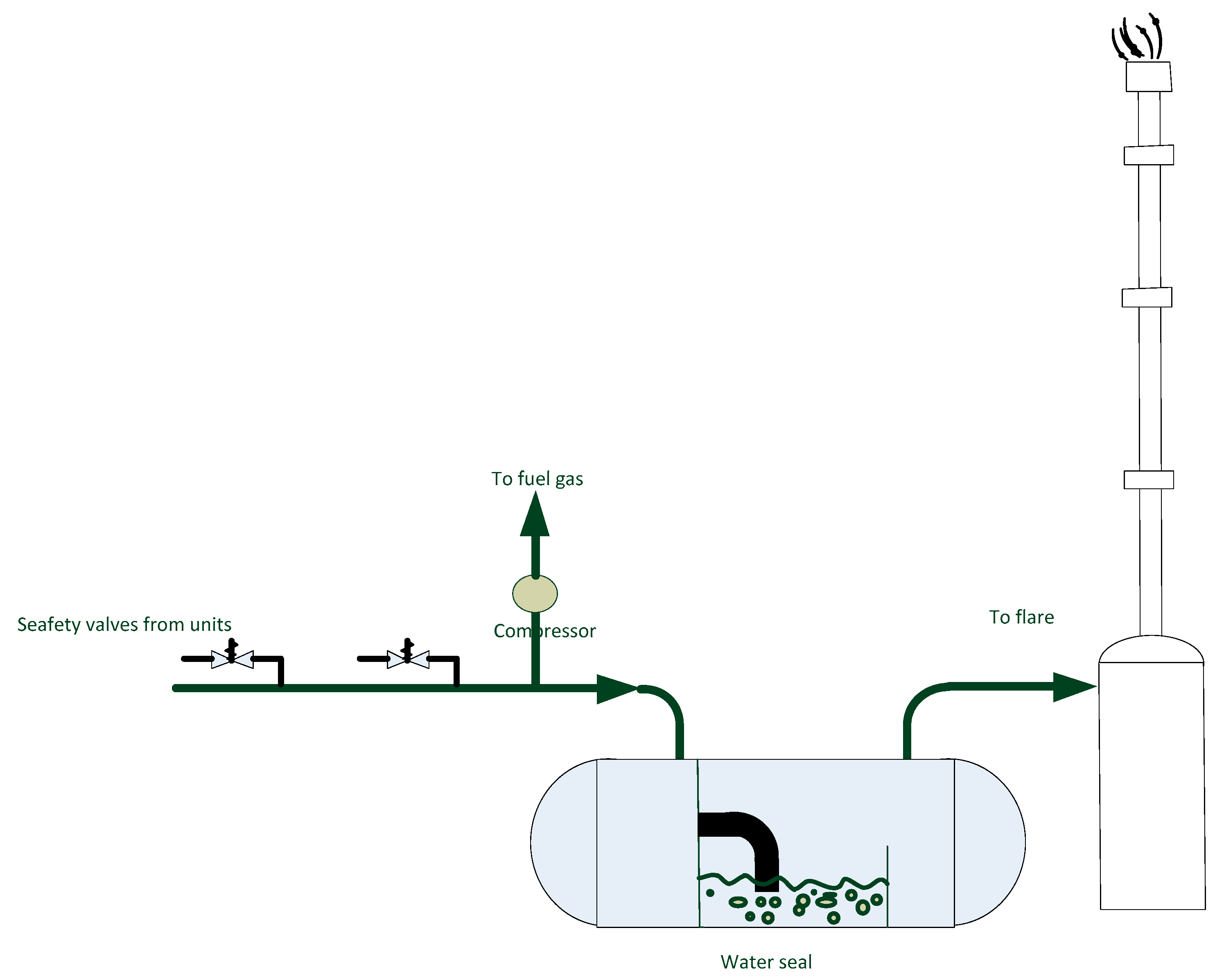
  • Gases are discharged from a given installation into a pipeline system and discharge collectors,
  • Within a given installation, the liquid phase is separated;
  • Gases leave the knockout drum (separator) built into the production plant and are further directed to the collectors cooperating directly with the flare stacks;
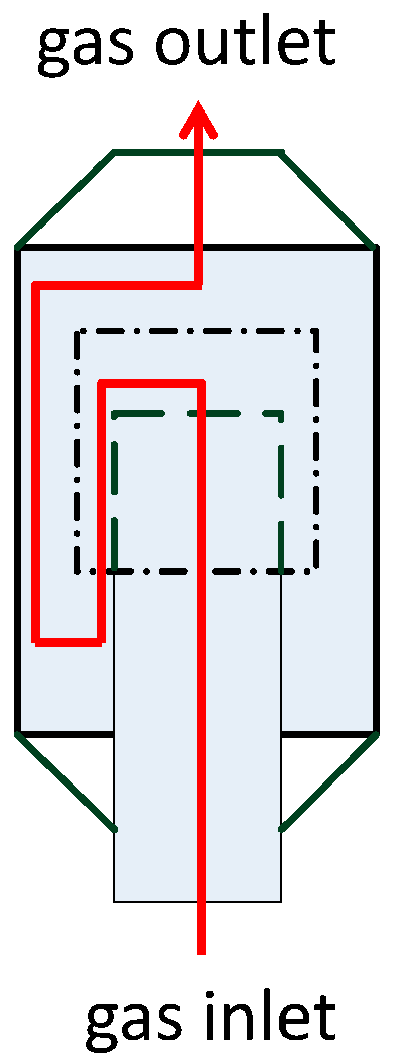
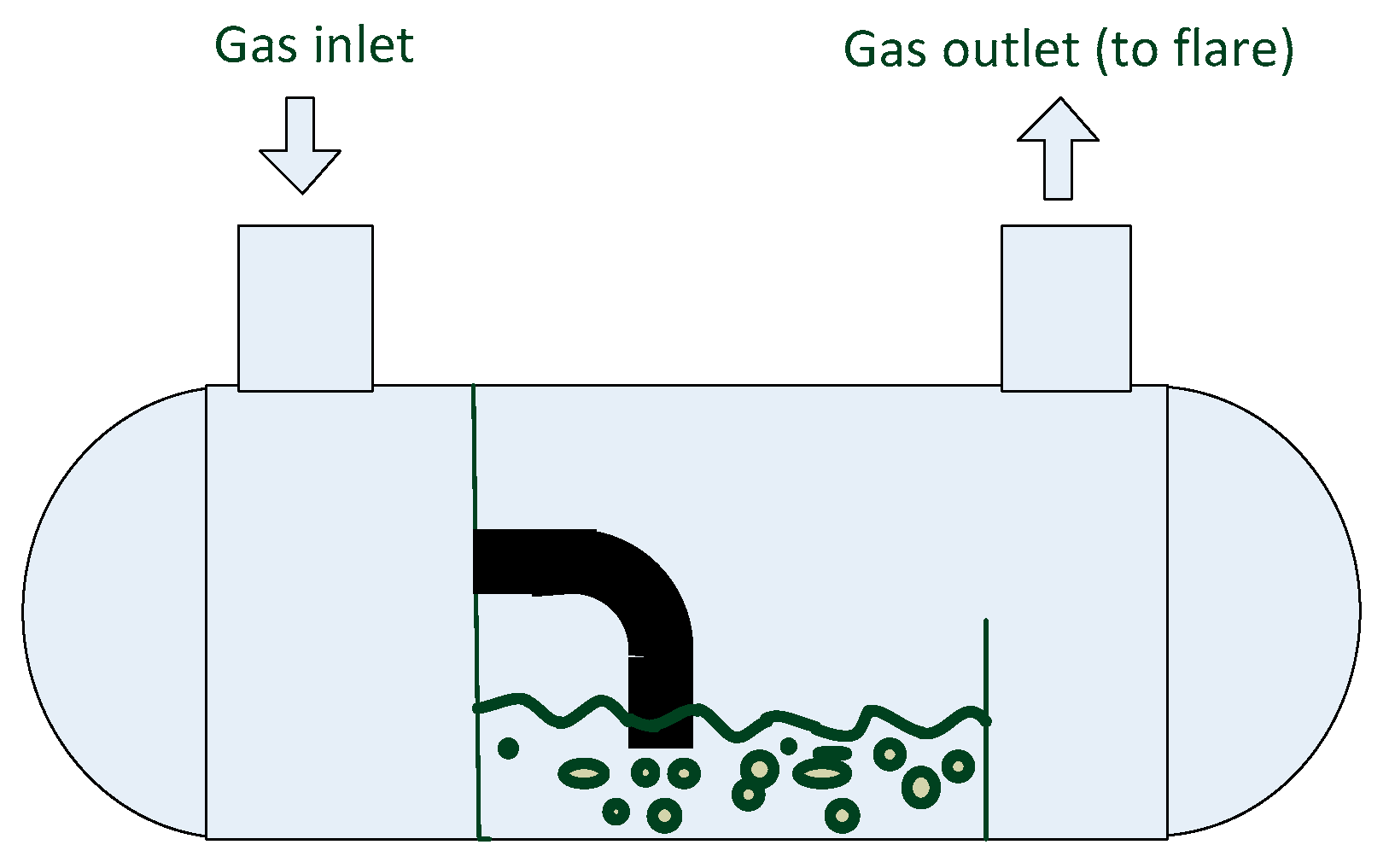
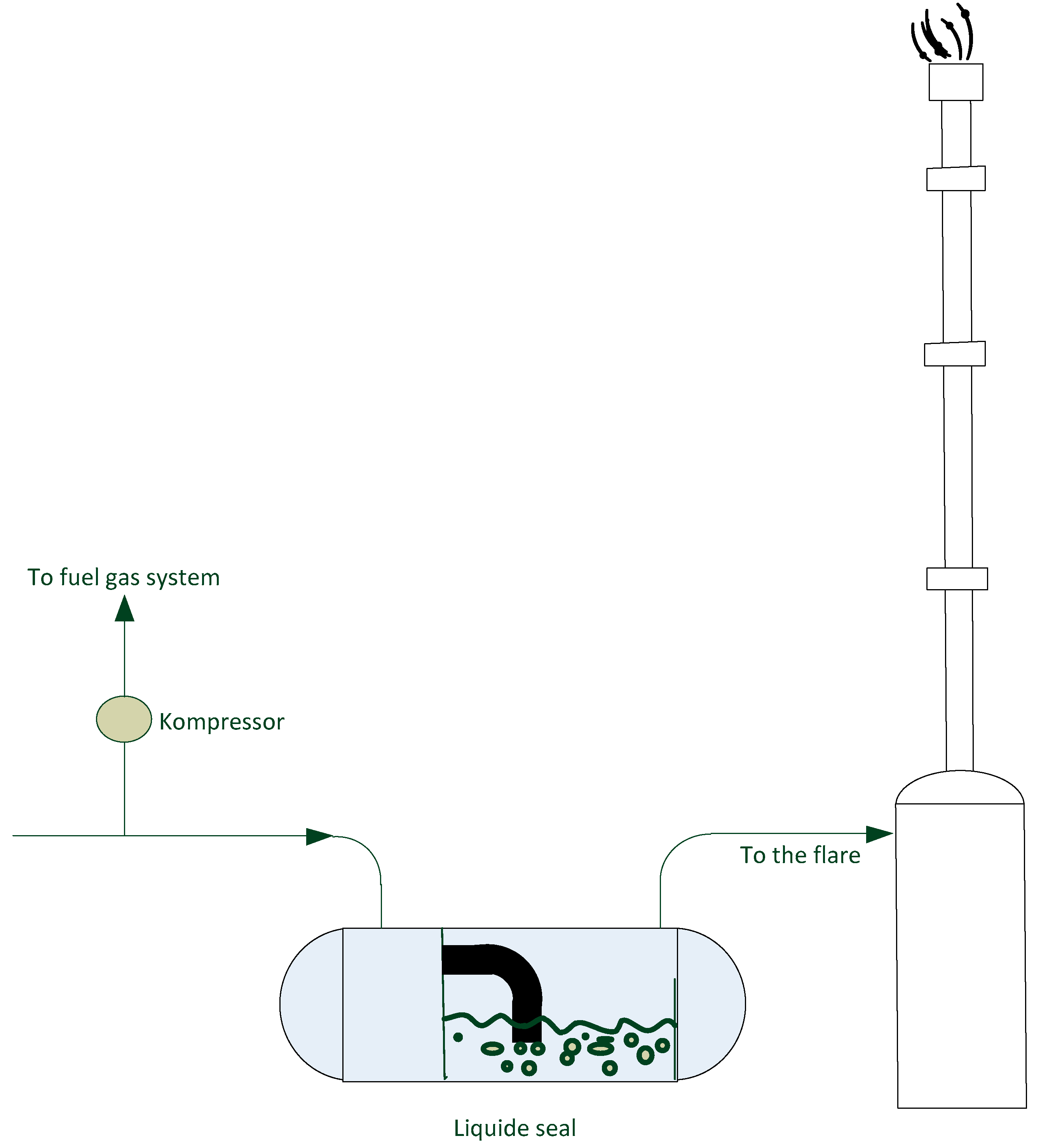
  • Flare gas streams pass through a knockout drums (separator), the KO may be integrated with a liquid seal that maintains the pressure of the flare gases at the required level;
  • The maintained pressure of the flare gases ensures their influx into the suction of the compressor,
  • The compressor the pressure of the gases is increased to the required value,
  • Directing gases to the internal fuel gas system.
The problem is the quality of recovered streams, which can be very variable over time. By controlling individual streams through the use of existing pipelines or construction of dedicated pipelines, it is possible to control and maintain the stream of recovered gases with constant and more stable quality.
The discharge gases, after a few, usually two, stages of separation and compression liquid hydrocarbon, are directed to the internal fuel gas system, which is used for heating of the process furnaces [15,16].

3.2. The Use of Surplus of Discharge/Flare Gases beyond Manufacturing Plants

In production practice, there are technological situations during which it is not possible to use all the gas streams in the existing networks of fuel gas. In manufacturing plants, one type or several types of fuel gas networks, in the aspect of system-work pressure, can be used, which may differ in terms of gas pressure as well as its quality. During normal stable operation of the refinery, these systems are mostly largely balanced. The balancing can also take place in a different way, appropriate for a given refinery or a given production plant. There are refineries which do not have connection to an external gas source, e.g., natural gas. Then balancing may be made, for example, by evaporation of a portion of LPG and directing it to the main fuel gas collector. In the fuel gas system, the most common is participation of light hydrocarbons: C1, C2, and lower amounts of C3 and C4 hydrocarbons and H2. Introduction of a larger part of C3 and C4 hydrocarbons into the fuel gas network causes a number of difficulties in the functioning of such a system, especially in periods of low ambient temperatures. In this case, there is a risk of condensation of heavier hydrocarbons and problems with burners built on technological furnaces. There may also be problems on pilot burners of flares. However, there are also situations in which the excess fuel gas is unproductively burnt in flares—the system is imbalanced. An example of such a case is the failure of the production installation, which is a large consumer of the fuel gas. The average composition of the flare gas and natural gas is presented in Table 1 [17,18].
Based on the results presented in Table 1 it is possible to conclude that the amount of energy contained in the flare gases is 63.14 MJ/m3, while in the case of the natural gas stream it is 35.8 MJ/m3, whereas the calorific values are equal 48.33 MJ/kg and 46.09 MJ/kg, respectively. In case of simple injection of 1 Mg/h of the flare gas into the natural gas pipeline (with flow equals 30 Mg/h), the methane content will decrease to 94.97%, nitrogen slightly decrease to 1.77%, while hydrogen sulphide content increase to 8 ppm/kg. Gas density increase from 0.740 kg/m3 to 0.748 kg/m3. Based on that simple calculation it is possible to conclude that injection of the flare gases to the natural gas system is technically feasible. Thus, it is possible to inject the non-balancing flare gasses produced in the refinery plats into existing methane pipeline system. Moreover for the presented in Table 1 composition of flare gases the amount of produced CO2 in the combustion of 1 Mg of this gas is equal 2.91 Mg.
There are also refineries that are connected to the natural gas system. Then, during the shortage of own fuel gas caused by stopping for repair or emergency stop of the installation, which is a large producer of fuel gas, the refinery complements the shortages by supplying gas from the external natural gas network.
In periods in which the current technological system in the refinery generates surplus fuel gas, or surpluses of other gas streams—technological streams and hydrogen gas streams (as mentioned, these are situations related to the retention of individual production installations or their groups for renovation or when we are dealing with situations Emergency systems that generate such streams).
A solution that would eliminate the need for unproductive combustion of the discharge gas in utilization flares is to take them out of production plants and take them, for example, to an existing natural gas transmission pipeline or to a nearby heating plant or a combined heat and power plant burning gas for energy.
Before leaving the industrial plant, the gases have to be properly identified, catalogued and prepared. Among the most important activities that should be performed before implementing such solution, first of all it is necessary to specify the following:
  • Gas streams that can be found in the flare discharge system, which are dedicated to individual processes/installations;
  • Quality of these streams;
  • Amount of discharge gas;
  • Variability of their composition; and
  • Content of impurities.
Knowing the gas streams (based on the processes carried out) that can be found in a given depressurization system, one may initially determine the quality of these gases. Based on this knowledge, one may decide whether a given stream should be sent for recovery or it should be burnt in a flare stack. Knowledge about the gas streams makes possible determination of the composition of these gases (the content of individual hydrocarbons) by applying analytical methods dedicated for this purpose. As a consequence, it is possible to select carefully gases that should undergo recovery. Determination of the number of discharge gas streams will allow determining the output capacity of the discharge gas recovery installation. In the refinery plants located in Europe, this is not a problem as a result of provisions of Commission Regulation (EU) No 601/2012 of 21 June 2012 on the monitoring and reporting of greenhouse gas emissions pursuant to Directive 2003/87/EC of the European Parliament and of the Council. The most commonly used measurement method is ultrasonic measurement. The measuring systems were installed on the flare stacks, i.e., at the end of the depressurization system. This solution indicates all the flare gases (excluding inert gases). A better way to determine accurately the amount of discharge gases is to use the plant balance. This method is much more precise. Knowing the quantity and quality of these streams, you can determine their variability. This parameter allows to determine the impact of a given industrial gas stream on the quality of natural gas, transported by a specific pipeline system in the event, when the industrial gas was pumped into the transmission gas pipeline. The necessary condition is knowing the quality and quantity of natural gas flowing through the pipeline. It is also important to identify impurities in the industrial stream. In the case of high-methane natural gas, the content of CH4 is very stable and basically does not decrease below 95%. The other components are methane homologs—as their molecular weight increases, their share in the natural gas stream decreases. From the point of view of natural gas utility, it is very important to ensure in the stream of industrial gas, which could be directed to the transmission system, that there is as little as possible heavier hydrocarbons, nitrogen, and sulfur compounds.
A larger amount of heavier hydrocarbons is a threat of their condensation and subsequent problems during transport and use. Nitrogen is an inert gas which is unnecessary from the point of view of transport and use—it significantly reduces the calorific value of fuel. Sulfur compounds can be very toxic (e.g., hydrogen sulfide) and could pose hazards related to the safety of use, they also constitute a significant corrosion hazard. The above mentioned components are always undesirable from the point of view of the industrial use of natural gas, for example for the production of hydrogen and heating industrial furnaces.

4. Conclusions

The recovery and output of excessive flare gases (in order to use them for energetic purpose) beyond the production plants is a solution possible to introduce in case of refinery and petrochemical plants. There are situations in which there is a surplus of gases: heating, technological, or discharge ones, characterized by good quality. This solution is possible for production plants in the vicinity of which natural gas transmission pipelines exist.
The following are facts confirming the applicability of the assumptions described in the paper:
  • The quality of the discharge gases generated at individual production installations is known. It is possible to take samples for analysis and have them analyzed in the laboratory. It is also possible to install a chromatograph, which would be used for continuous monitoring and quality control of the selected gas parameters.
  • The quality of the natural gas, pumped through the individual transmission pipelines, is known. The technical parameters of transmission pipelines are also known. Also technical requirements for these objects defined in the regulations and technical specifications are known.
  • It is possible to determine the impact of the compressed and injected stream of flare gas on the quality of natural gas transported by the selected transmission pipeline, or under the selected system of transit. Knowing the quality and quantity of the discharge gas and natural gas, it is possible to develop a mathematical model by which the gas stream quality can be determined after mixing two streams and then refer the results to the required natural gas quality described in the relevant standards.
  • The solution would generate the following beneficial effects on the production plants: Less use and thus consumption of infrastructure.
  • Reduced consumption of energy media in the depressurization flare stack systems, thus reducing the consumption of steam-producing fuels, used to atomize the flame on the flare main burner.
The demonstrated effects for industrial plants would at the same time limit the negative impact on the natural environment—the use of less fuels for steam production and a significant reduction in the flare gas burnt in the flares.

Author Contributions

Conceptualization, J.S. and A.S.; Methodology, J.S.; Investigation, J.S.; Writing—Original Draft Preparation, J.S. and A.S.; Writing—Review and Editing, J.S. and A.S.; Supervision, A.S.

Funding

This research received no external funding.

Conflicts of Interest

The authors declare no conflict of interest.

References

  1. Mehraban, M.; Shahraki, B.H. A mathematical model for decoking process of the catalyst in catalytic naphtha reforming radial flow reactor. Fuel Process. Technol. 2019, 188, 172–178. [Google Scholar] [CrossRef]
  2. Shi, J.; Hou, Y. Practice and Analysis of FCCU Efficient Operation Based on Synergy of Refinery. Petr. Process. Petrochem. 2019, 50, 42–46. [Google Scholar]
  3. Zhang, J.; Cao, Z.; Wu, Z. Investigation of the technology that can maximize chemical feedstock production by hydrocracking straight-run diesel for Tianjin Petrochemical Company. Petr. Refin. Eng. 2018, 48, 25–27. [Google Scholar]
  4. Li, R.; Zhang, X.; Li, S.; Li, Z. Analysis of Guo VI gasoline upgrading processes for refineries producing ethanol gasoline blendstocks. Petr. Refin. Eng. 2017, 47, 9–13. [Google Scholar]
  5. Ozren, O. Oil Refineries in the 21st Century: Energy Efficient, Cost Effective, Environmentally Benign; Wiley-VCH Verlag GmbH & Co. KGaA: Weinheim, Germany, 2005. [Google Scholar]
  6. He, Y. Analysis and practice of operation optimization of hydrogen system. Petr. Refin. Eng. 2017, 47, 14–17. [Google Scholar]
  7. Al-Subaie, A.; Maroufmashat, A.; Elkamel, A.; Fowler, M. Presenting the implementation of power-to-gas to an oil refinery as a way to reduce carbon intensity of petroleum fuels. Int. J. Hydrog. Energy 2017, 42, 19376–19388. [Google Scholar] [CrossRef]
  8. Wu, C.; Li, Y.; Zhou, Y.; Li, Z.; Zhang, S.; Liu, H. Upgrading the Chinese biggest petrochemical wastewater treatment plant: Technologies research and full scale application. Sci. Total Environ. 2018, 633, 189–197. [Google Scholar] [CrossRef] [PubMed]
  9. Hou, M.; Miao, X. Analysis of factors affecting light olefins’yields of catalytic cracking unit and optimization. Petr. Refin. Eng. 2018, 48, 5–9. [Google Scholar]
  10. Yang, J.C.; Chang, P.E.; Chie, W.C.; Liu, J.P.; Wu, C.F. Large-scale search method for locating and identifying fugitive emission sources in petrochemical processing areas. Process Saf. Environ. Protect. 2016, 104, 382–394. [Google Scholar] [CrossRef]
  11. Arendt, J.S.; Casada, M.L.; Rooney, J.J. Reliability and hazards analysis of a cumene hydroperoxide plant. Plant/Oper. prog. 1986, 5, 97–102. [Google Scholar] [CrossRef]
  12. Franek, L.; Galbfach, R.; Rosciszewski, A.; Urbanski, J.; Zebrowski, M. Cumene Phenol Production—Development of the Technology in Mazovian Refining and Petrochemical Plants in Plock. Przem. Chem. 1985, 64, 522–524. [Google Scholar]
  13. Kalat Jari, H.R.; Borhani Sazeh, A. Minimize Flaring with Modification to Flare Gas Recovery Unit. Available online: http://gasprocessingnews.com/features/201804/minimize-flaring-with-modifications-to-flare-gas-recovery-unit.aspx (accessed on 8 March 2019).
  14. Baukal, C.E. Combustion Handbook, Design and Operations; CRC Press, Taylor & Francis Group: Boca Raton, FL, USA, 2013. Available online: http://vr360app.ternium.com/the_john_zink_hamworthy_combustion_handbook_second_edition_volume_2_design_and_operations_industrial_combustion.pdf (accessed on 8 March 2019).
  15. Environmental Protection Agency (EPA). Installing Vapor Recovery Units on Storage Tanks. 2006. Available online: https://www.epa.gov/sites/production/files/2016-06/documents/ll_final_vap.pdf (accessed on 8 March 2019).
  16. Mokhatab, S.; Mak, J.Y.; Valappil, J.V.; Wood, D.A. Handbook of Liquefied Natural Gas; Elsevier: Oxford, UK, 2014. [Google Scholar]
  17. Peterson, J.; Cooper, H.; Baukal, C. Minimize facility flaring. Hydrocarb. Process. 2007, 6, 111–115. [Google Scholar]
  18. Gas System (GS). 2019. Available online: https://www.gaz-system.pl/ (accessed on 8 March 2019).
Figure 1. Division of flares in view of their construction: (A) self-supporting flare, (B) flare with guy-ropes, and (C) flare with a lattice construction.
Processes 07 00253 g001
Figure 2. A fire closure as a part of the molecular closure.
Processes 07 00253 g002
Figure 3. A typical water closure in horizontal arrangement.
Processes 07 00253 g003
Figure 4. Diagram of the installation recovering the discharge gases, which are “recycled” to the internal heating gas network of the production plant.
Processes 07 00253 g004aProcesses 07 00253 g004b
Table 1. The average composition of the flare gases and natural gas [17,18].
NoGas ComponentsFlare Gases, %v/vNatural Gas, %v/v
1Methane43.60096.470
2Ethane3.6601.300
3Propane20.0300.278
4n-Butane2.7800.050
5Isobutane14.3000.040
6n-Pentane0.2660.010
7Isopentane0.5300.020
8neo-Pentane0.0170.000
9n-Hexane0.6350.000
10Ethylene1.0500.000
11Propylene2.7300.000
121-Butene0.6960.000
13Carbon monoxide0.1860.000
14Carbon dioxide0.7130.000
15Hydrogen sulfide0.2560.577 *
16Hydrogen5.5400.000
17Oxygen0.3570.000
18Nitrogen1.3001.778
19Water1.1400.0095 **
* mg/m3; ** g/m3.

