1. Introduction
With the advancement of modern industrial technology and process control mechanisms, an industrial process has become more and more complex [
1,
2]. To improve the industry process safety and product quality, process monitoring and fault diagnosis have received lots of attention over the past few decades [
3]. Data-driven multivariate statistical process monitoring (MSPM) has been widely applied to the monitoring of industrial process operations and production results. Compared to knowledge-based methods and model-based methods, MSPM methods are more accessible to establish with less or even no demand of the accurate kinematic equations [
4,
5]. As a result, MSPM models, such as principal component analysis (PCA) and independent component analysis (ICA), are widely used in industrial process monitoring and fault diagnosis [
6].
Traditionally, the framework of fault diagnosis includes two main steps: (1) feature extraction; and (2) fault classification. In the feature extraction step, many methods have been proposed to map the raw data from the high-dimensional space into a low-dimensional feature space, and then perform fault diagnosis in that feature space. The PCA, ICA, partial least squares (PLS), and linear discriminant analysis (LDA) are the most widely used feature extraction methods in the fields of fault diagnosis. In the second step, various classifiers, such as neural networks of multi-layer perceptron (MLP) [
7], support vector machine (SVM) [
8], Bayesian discriminant functions [
9], and adaptive neuro-fuzzy inference system (ANFIS) [
10], have been applied for fault classification. “Feature extraction + classification” fault diagnosis strategies like PCA + SVM and ICA + MLP have obtained satisfactory results. However, static modelling methods like PCA and LDA assume that data samples are collected independently from sensors without sequence correlation. It is well known that most industrial processes evolve from past operation situations to potential future events [
11]. Therefore, dynamic behavior should be one of the essential characteristics of industrial process data [
12]. In order to extract the dynamic features of the sequence data, dynamic principal component analysis (DPCA) [
13] and dynamic linear discriminant analysis (DLDA) [
14], among others, has been developed by augmenting each measurement with a fixed length of several previous measurements and aligned to a stacking matrix [
15]. Some fault diagnosis methods for the dynamic process like DPCA-SVM and DLDA-SVM have been developed. However, conventional methods still have some obvious drawbacks as follows:
- (1)
Vector-based augmentation may aggravate the “curse of dimensionality” problem and make the feature extraction methods unstable [
16,
17].
- (2)
Feature extraction and classification both affect the diagnosis performance but are designed individually. This is a divide and conquer strategy that cannot be optimized simultaneously.
- (3)
The extracted features are usually hand-crafted, requiring much prior knowledge about process monitoring techniques and diagnostic expertise, which is time-consuming and labor-intensive.
With the rapid advancement of machine learning, deep learning has developed as an efficient way to overcome the above drawbacks. Deep learning can learn the abstract representation features of the raw data automatically, which could avoid the requirement of prior knowledge. Deep learning is a branch of machine learning algorithms that attempt to model complexity and internal correlation in a dataset by using multiple processing layers, or with complex structures, to mine the information hidden in the dataset for classification or other goals [
18]. In recent years, deep learning has developed rapidly in academic and industrial fields. Tang et al. applied deep belief networks (DBNs) to fault feature extraction and diagnosis of the chemical industry and introduced the quadratic programming method to estimate the sparse coefficients simultaneously class by class [
18]. Wen et al. convert fault signals into two-dimensional (2-D) images and adopt convolutional neural networks (CNNs) to extract the features of the converted 2-D images [
19]. However, the above methods are all static network applications. Hochreiter et al. proposed recurrent neural networks (RNNs) [
20]. An RNN is more suitable for fault diagnosis of dynamic processes because an RNN takes full account of the associations among samples. This association is represented by the connection of neurons in the RNN’s hidden layer. You et al. adopted an RNN to diagnose battery states in electric vehicle systems and determine the replacement time for a battery or to assess the driving mileage [
21].
Gated recurrent unit (GRU) [
22], a variant of RNN, not only retains all the advantages of RNN but also adds “gate” operations to its hidden layer neurons, which allows GRU to maintain useful information and discard useless information in dynamic sequence data automatically. A GRU demonstrates state-of-the-art performance on sequential problems including natural language processing, image classification, and time series prediction. For the purpose of diagnosing the faults of dynamic process accurately, quickly, and effectively, this paper proposes a three stage fault diagnosis method-based GRU deep network. The main contributions of this paper are as follows:
- (1)
Following the fault diagnosis framework, we propose a three-stage method. In the first stage, a moving horizon is adopted to process dynamic process data such that raw data is entered into the GRU without losing any dynamic information. In the second stage, we apply the GRU deep network belonging to deep learning to the extract the dynamic feature of sequential data. Moreover, in the third stage, softmax regression is adopted to obtain the output with a probabilistic explanation.
- (2)
Two diagnostic case studies were used to validate the proposed method. In the Tennessee Eastman (TE) case, the parameter selection of the method was studied in depth. Furthermore, the proposed method is compared to the conventional methods. The comparison results show the superiority of the method. In the case of para-xylene (PX) oxidation process, the diagnosis results show that the method can be easily and effectively applied to other diagnostic problems.
- (3)
Considering the covariate shift in deep learning and the over-fitting caused by the “curse of dimensionality,” BN is applied to our method to reduce the training time of GRU and improve the accuracy of fault diagnosis.
This paper is organized as follows. In
Section 2, a simple RNN and its variant GRU are introduced in detail. Meanwhile, batch normalization and softmax regression are briefly described.
Section 3 details the proposed three-stage learning method. In
Section 4 and
Section 5, the efficiency and accuracy of the proposed method are illustrated in the TE process as well as the PX oxidation process. Finally, the conclusion is provided in
Section 6.
2. Recurrent Neural Network and Softmax Regression
2.1. Concept of an RNN
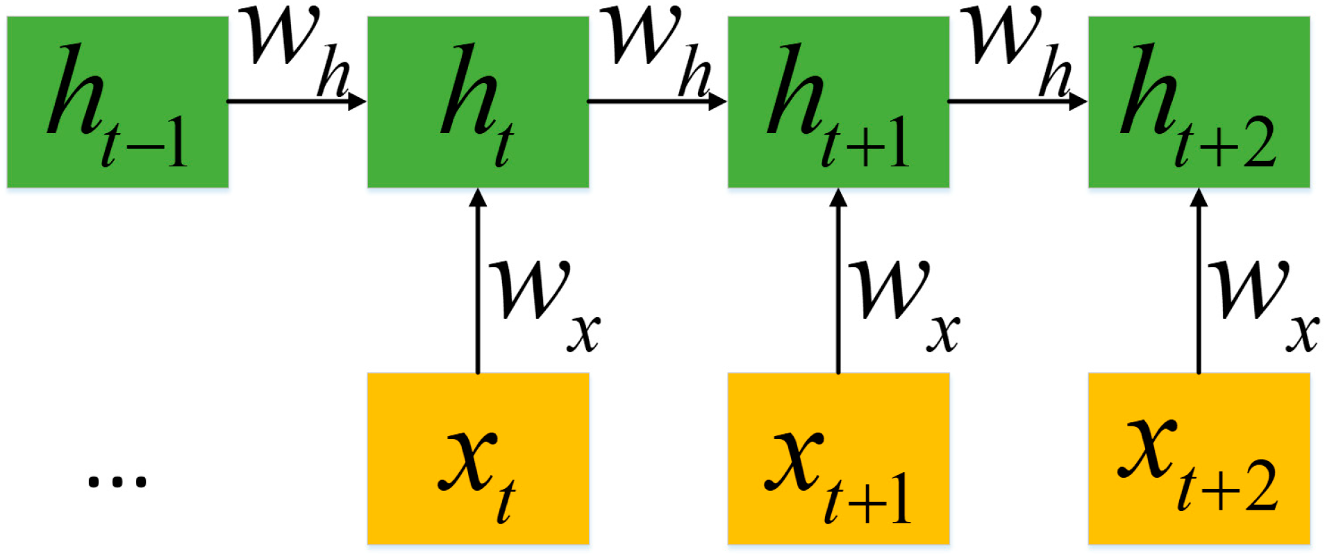
An RNN is called recurrent because they perform the same task for each element in the sequence. The RNN uses the hidden state to record the state of each moment while processing the sequence data, and the current state depends on the current input as well as the state of the previous moment. Therefore, the current hidden state makes full use of past information. In this way, an RNN can process sequence data in dynamic processes. The architecture of an RNN is shown in
Figure 1. When given an input sequence
of length
, an RNN defines the hidden state
at the time
of a sequence as:
where
is the weight matrix between hidden layers,
is the weight matrix of the input layer to the hidden layer, and
is the bias.
,
,
, and the initial state
are parameters of the RNN. The
is the activation function.
Although the RNN is very powerful when dealing with sequence problems, it is difficult to train with the gradient descent method because of the well-known gradient vanishing/explosion problem [
20]. On the other hand, variants of RNN have been developed to solve the above problems, such as Long Short-Term Memory (LSTM), GRU, etc. Among them, GRU avoids overfitting, as well as saves training time. Therefore, GRU is adopted in our method.
2.2. Concept of a GRU
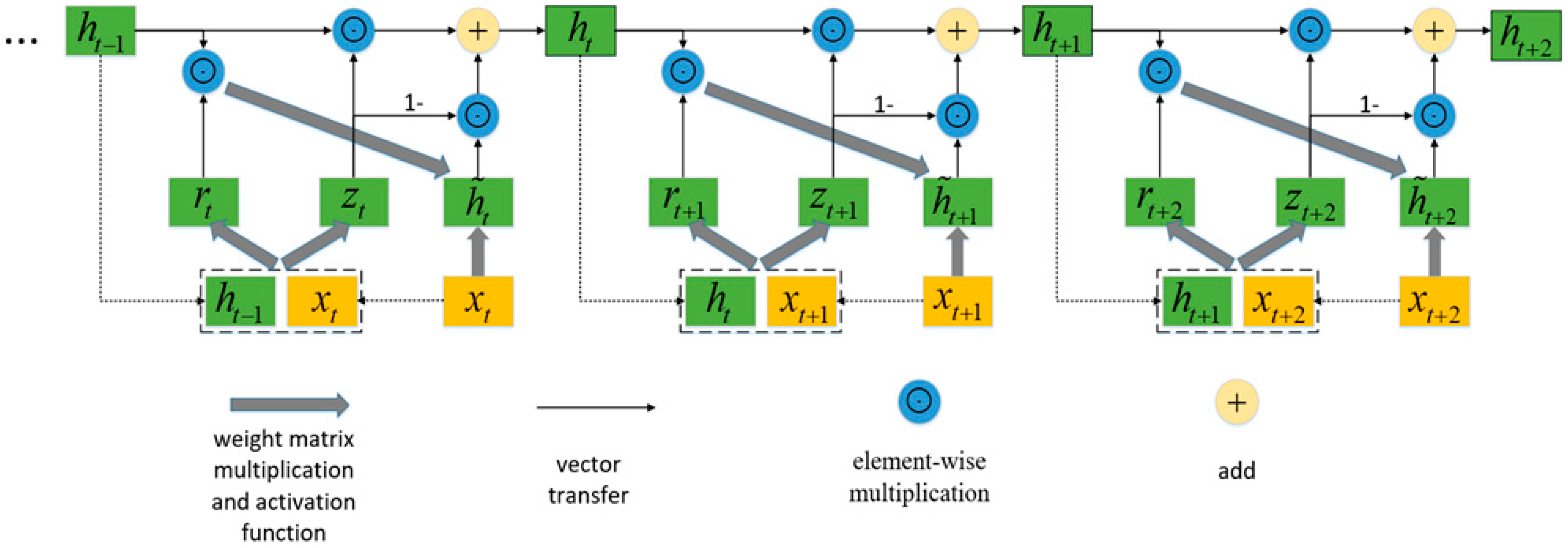
GRU has the same chain structure as a simple RNN, but a GRU is more complicated in the way it updates the hidden state. Instead of directly updating the current hidden state with the previous hidden state, GRU uses a reset gate and updates the gate, which can judge whether the information in the previous hidden state is useful, then holds useful information and removes useless information.
Figure 2 shows the architecture of GRU. The way GRU updates
is as follows:
(1) The reset gate
and update gate
:
The activation function is the sigmoid function, and the value range of each element in the reset gate and the update gate are [0, 1].
(2) Candidate hidden state:
The candidate hidden state uses the reset gate to control the inflow of the previous hidden state containing past information. If the reset gate is approximately zero, the previous hidden state will be removed. Therefore, the reset gate provides a mechanism to remove previous hidden states that are unrelated to the future; that is, the reset gate determines how much information was forgotten in the past.
The hidden state
uses the update gate
to update the previous hidden state
and the candidate hidden state
. If the update gate is approximately 1, the previous hidden state will be held and passed to the current moment. When given an input sequence
of length
, GRU passes the last hidden state
through a nonlinear transformation as the output.
In the above formula are the weight matrices of the hidden layer to the hidden layer, are the weight matrices of the input layer to the hidden layer, is the weight matrix of the output layer and are the bias , and the initial states are the parameters of the GRU.
The GRU can cope with the gradient vanishing/explosion problem in the RNN, so it is more suitable for the fault diagnosis of dynamic processes.
2.3. Batch Normalization-Based GRU
It is known that for deep neural networks, an internal covariate shift is a common phenomenon where the features presented to a networks change in distribution during the process of training [
23]. When using a GRU that resembles very deep feed-forward networks to process sequence data for dynamic processes, this internal covariate shift may play an especially important role. In order to reduce internal covariate shift, batch normalization was proposed recently. Batch normalization involves standardizing the activations going into each layer, enforcing their means
and variances
to be invariant to changes in the parameters of the underlying layers, so as to accelerate the training. Indeed, GRU network strained with batch normalization converge significantly faster and generalize better. The batch normalizing transform is as follows:
where
is the vector that will be normalized,
and
are model parameters that determine the mean and standard deviation of the normalized activation, and
is a regularization hyperparameter. The
denotes the Hadamard product (element-wise multiplication). According to Reference [
24] we set
and
equal 0. At training time, we use the mini-batch training strategy, which divides all training samples into many mini-batches, and each mini-batch carries out a parameter update. Therefore, the input of BN is the current mini-batch containing
k samples, which can be expressed as
.
is the sample mean and
is the sample variance.
We introduce the batch-normalizing transform into the GRU network. Batch normalization is adopted in the hidden-to-hidden transformations as follows:
2.4. Softmax Regression
In neural networks, softmax regression is often implemented at the final layer for multiclass classification. It is computed fast and can provide a result with a probabilistic explanation. Suppose that we have a training set
with its label
where
is the input sample and
is the label. It should be noted here that one should not confuse the input of softmax with the input of GRU. In fact, in our task, the input sample
here is the output
of the GRU network. For each input sample
, the model works to estimate the probability
for each label of
. Thus, the result of softmax regression will output a vector that gives
K estimated probabilities of the input sample
belonging to each label. Concretely, the result of softmax regression
takes the form:
where
are the parameters of the softmax regression model. It should be noticed that the term
normalizes the distribution such that the sum of the elements of result equals 1.
2.5. Loss Function and Optimizer
Based on the result, the whole model is trained by minimizing the cost function
:
where
is the set of parameters containing all the parameters above. As mentioned earlier, this article uses the mini-batch training strategy, so
here can be understood as a mini-batch. Furthermore, in the experiments in
Section 4 and
Section 5, the setting of the mini-batch will be given.
is the number of classes,
is the indicator function indicating that if the class of the
ith sample is
, then
, otherwise
.
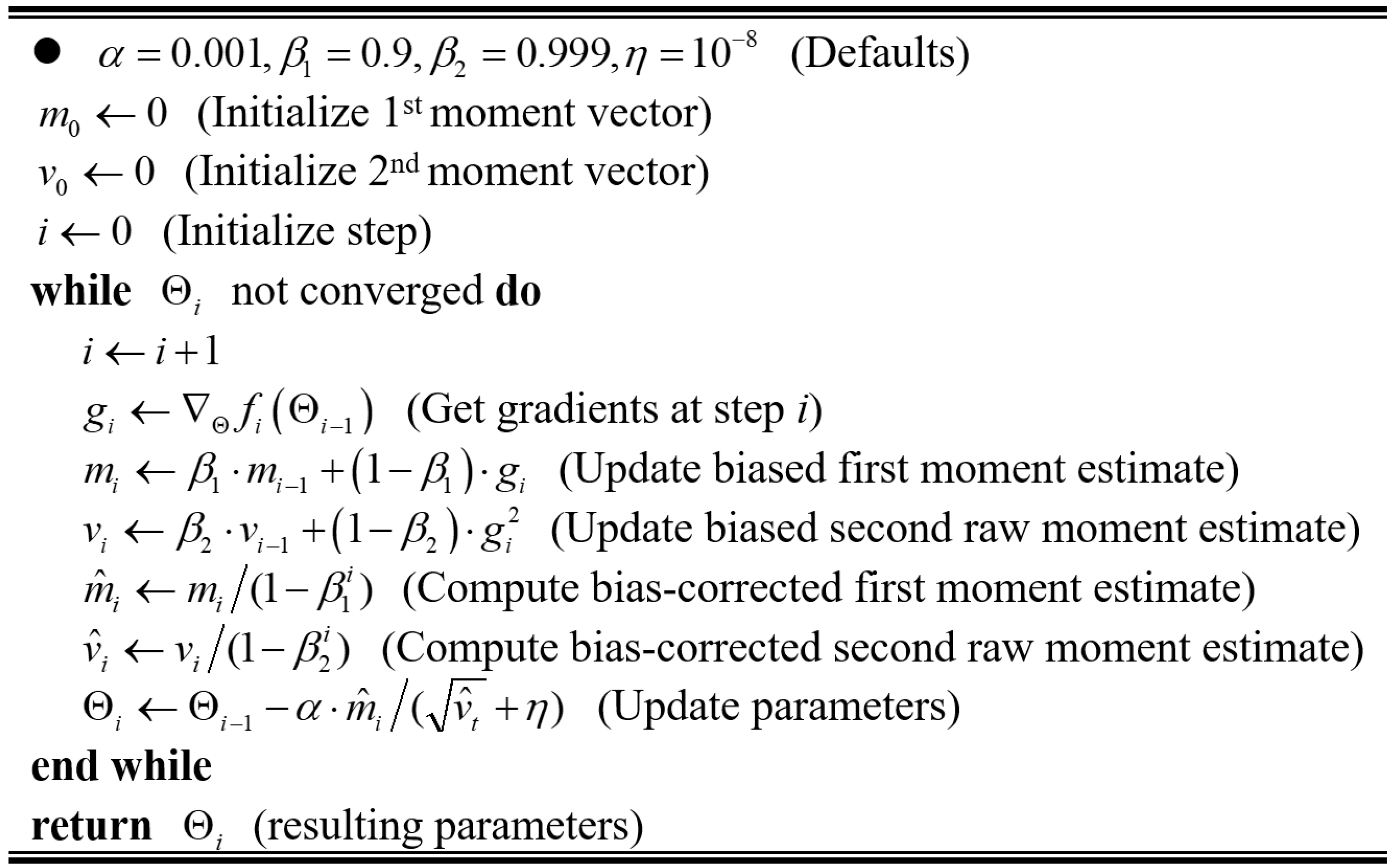
In this paper, we use Adam to optimize the loss function. Adam is a first-order optimization algorithm that can replace the traditional stochastic gradient descent process. It can iteratively update neural network parameters based on training data. The stochastic gradient descent maintains a single learning rate to update all parameters, and the learning rate does not change during the training process. Adam calculates independent adaptive learning rates for different parameters by calculating the first-moment estimation and second-moment estimation of the gradient. The pseudocode of the Adam algorithm for updating
is shown in
Figure 3. For more details regarding Adam, please refer to Reference [
25].
3. Three-Stage Fault Diagnosis Method of Dynamic Process
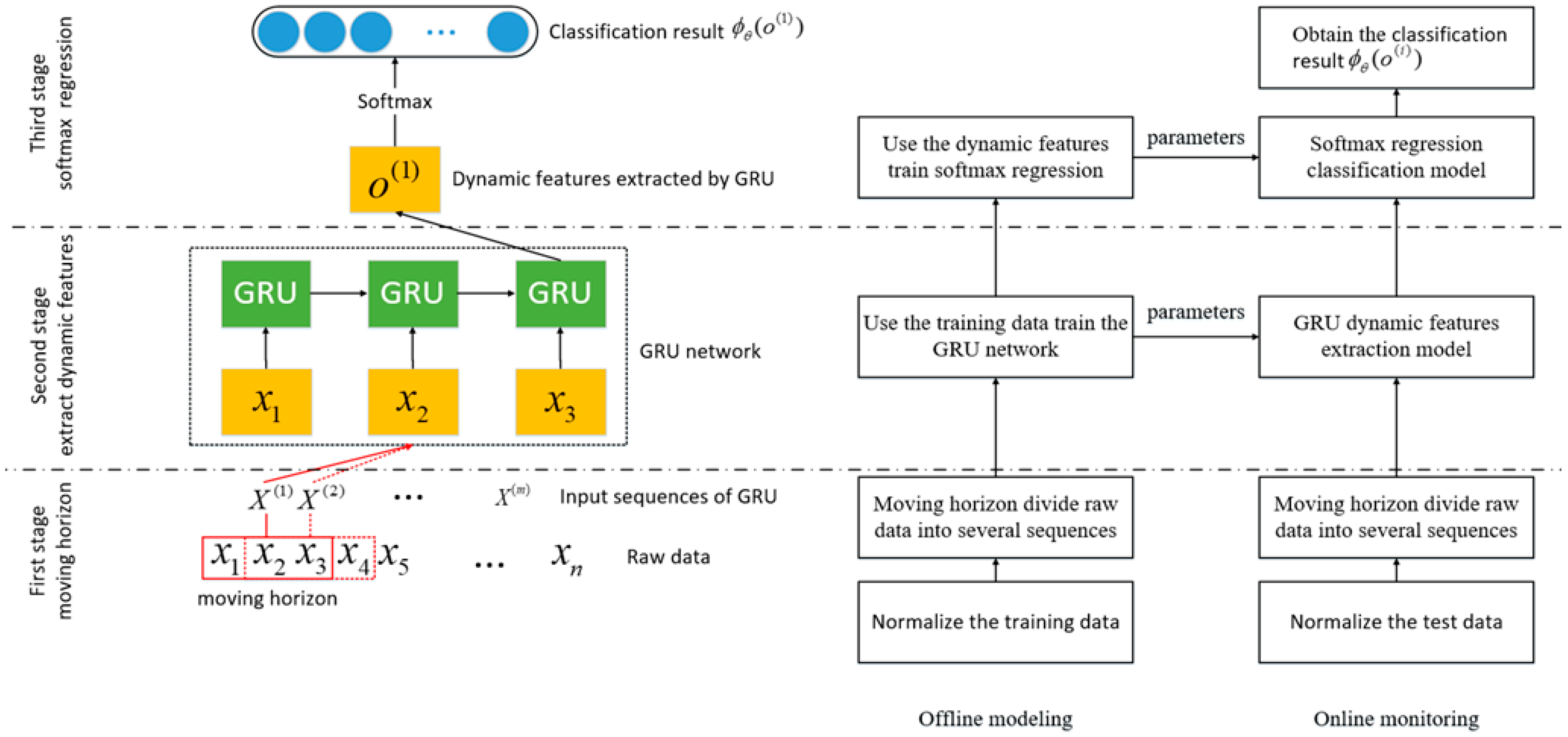
This section details the proposed three-stage fault diagnosis method for fault diagnosis of the dynamic process. The illustration and flowchart of the method are shown in
Figure 3. In the first stage, the moving horizon was used to process raw data as the input sequences of GRU. In the second stage, the GRU model was established through batch normalization, and the model was trained with sequences processed by moving horizon. In this way, the GRU model extracts the dynamic features in the raw data. In the third stage, softmax regression was applied to classify faults using the extracted dynamic features.
3.1. First Stage—Moving Horizon
In order to make full use of the correlation among sequential data of the dynamic process, we adopted the moving horizon to process the raw data. The width of the moving horizon can be adjusted according to different needs. The width of the moving horizon is the length of the input sequence which is defined as time steps (T) in GRU. For example, suppose there are n sets of raw data where , when the time steps are set to 3 (T = 3), then the moving horizon divides raw data into several sequences like ... such that there are m = n − T sequences, and each sequence is an input sample to the GRU neural network.
3.2. Second Stage—Extract Dynamic Features by GRU
Once the input sequences of GRU is obtained, we define the input in this way , , …, , where and . What needs to be explained here is that we just use T = 3 as an example. In fact, the time step can be adjusted according to different needs. Each input corresponds to an output refers to Equations (2), (3), (4), (5), and (6). During this time, the output vector is the dynamic features extracted by GRU.
3.3. Third Stage—Obtain Fault Diagnosis Result Using Softmax Regression
This section details the proposed three-stage fault diagnosis method for fault diagnosis of the dynamic process. The illustration and flowchart of the method are shown in
Figure 4. In the first stage, the moving horizon is used to process raw data as the input sequences of GRU. In the second stage, the GRU model is established through batch normalization, and the model is trained with sequences processed using a moving horizon. In this way, the GRU model extracts the dynamic features in the raw data. In the third stage, softmax regression is applied to classify faults using the extracted dynamic features. Once the dynamic features set
is obtained, we combined it with the label set
to train the softmax regression. The softmax regression model computes the probability that the feature
has the fault labels
as in Equation (12). The sum of the probabilities over all class labels being 1 ensures that the right side in Equation (12) defines a properly normalized distribution. After being trained, the maximum posterior probability in
indicates which fault label the feature
belongs to.
After the three stages, we used test samples to verify the proposed method. For example, there were new samples of a dynamic process , where , first, we used a moving horizon to divide it into several sequences as , , …, . Then, we put them into the GRU model and obtained the dynamic features extracted by the GRU. Finally, the faults of the test samples are decided by the trained softmax regression model using the dynamic features.
4. Case Study I: Fault Diagnosis of TE Using the Proposed Method
In this section, a GRU-based fault diagnosis algorithm is applied to the TE process, which is a benchmark case designed for testing the fault diagnosis performance. A model of this process was developed by Downs and Vogel [
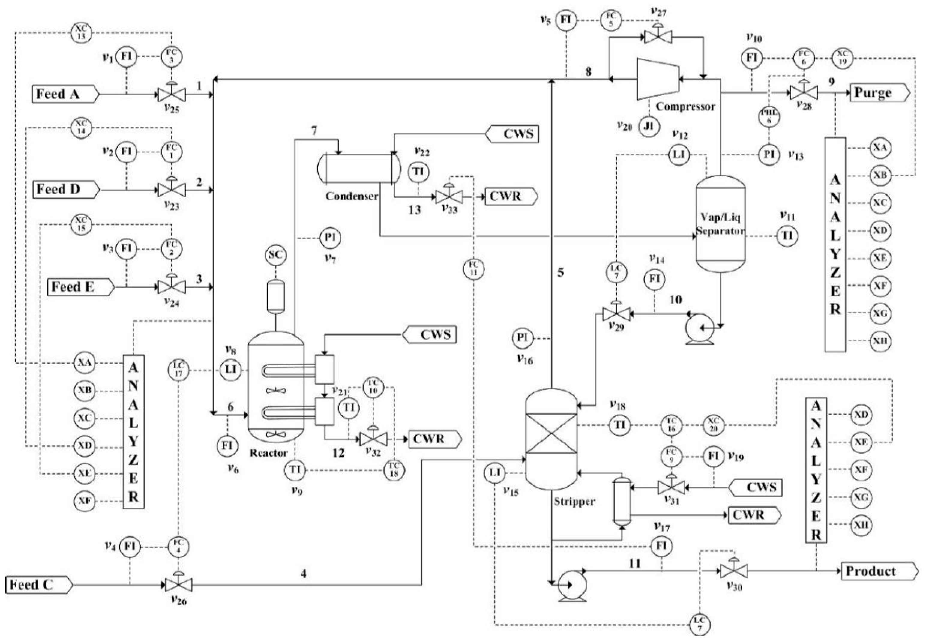
26], consisting of five major transformation units, which are a reactor, a condenser, a compressor, a separator, and a stripper, as shown in
Figure 5. The MATLAB codes can be downloaded from
http://depts.washington.edu/control/LARRY/TE/download.html. From this model, 41 measurements are generated along with 12 manipulated variables. A total of 21 different process upsets are simulated for testing the detection ability of the monitoring methods, as presented in
Table 1 [
27,
28]. Our goal is to diagnose and classify the faults that have occurred, so normal data is not used as a training sample.
The fault diagnosis algorithm in this paper is designed for time series problems or dynamic problems. We check whether the TE data has autocorrelation by calculating the autocorrelation coefficient of each variable of the TE data. The autocorrelation coefficient measures the degree to which the same event is correlated between two different periods. Suppose that the process has mean
and variance
at time
t. Then the definition of the autocorrelation between times
and
is:
where “
E” is the expected value operator,
t is the lag, and
. We selected a feature corresponding to the fault occurrence in the fault data of the TE process to calculate its autocorrelation between the time
and
,
.The calculation results are shown in
Figure 6. In the figure, approximate 95% confidence intervals are drawn with blue lines. From the results, this feature does have autocorrelation. Therefore, due to the recurrent structure and adaptive training strategy of the GRU, our proposed algorithm can fully extract the dynamic information in TE for further fault diagnosis.
4.1. Data Description
The experimental dataset was generated by the TE simulation model, and 21 types of faults could be simulated. The simulation times of the training and the test sets were 24 h and 48 h, and the faults appeared after 1 h and 8 h, respectively. There were 480 sets of data for each fault as the training set. There were 800 sets for each fault as the test set. Since faults 3, 9, and 15 were difficult to diagnose with a data-based method, these three faults were not considered in our experiment. Therefore, there were a total of sets training data and sets of test data.
4.2. Hyperparameters Selection and Fault Diagnosis Result and Analysis
4.2.1. Hyperparameters Selection
Our GRU model contains two important hyperparameters: the number of GRU layers and the width of the moving horizon. We evaluated the accuracy for the GRU with different layers and different width of the moving horizon. The epochs of training were set to 30. Each accuracy was the result of averaging ten experiments, and the results are given in
Table 2.
It is concluded from the table that when the number of GRU layers is set to one, and the width of the moving horizon is set to three and four, the accuracy reached a peak, but it decreased with the further increase of the width and the number of layers. The reason for this phenomenon was that as the number of GRU layers and the width of moving horizon increased, the amount of parameters, such as weights and biases in the model, was multiplied, which made the model’s generalization ability worse and easy to overfit when dealing with high-dimensional industrial data.
Therefore, the network structure and hyperparameters are as follows: the number of GRU layers was set to 1, the width of the moving horizon was set to 3, the dimension of the hidden state was set to 30, and the parameters of batch normalization algorithm and were set to 0. In the training, the mini-batch was set to 128, and the number of epochs was set to 30.
Experiments were run on a computer with Intel Core i7-7700 CPU, 8GB memory, and an NVIDIA GeForce GTX 1060 GPU. The diagnosis results of 21 faults are shown in a confusion matrix of
Figure 7, where the confusion matrix considers target and output data. The target data are ground truth labels corresponding to 21 types of faults. The output data are the outputs from the tested method that performs classification. In the confusion matrix, the rows show the predicted class, and the columns show the ground truth. The diagonal cells show where the true class and predicted class match and the proportion. The off-diagonal cells show instances where the tested algorithm made mistakes and the proportion. The darker the color of the diagonal cell, the better the classification effect.
Figure 6 has shown that only the diagnosis effect of fault 21 was not ideal, but the rest of the diagnosis results were satisfactory, with many fault diagnosis accuracy rates over 90%, and the mean accuracy was 87.36%.
In practical applications, we can collect online data during online monitoring and re-model and update parameters at regular intervals because the proposed model requires little computational cost and time cost. In this way, the diagnosis accuracy will be further improved. This is one of the advantages of the proposed model.
4.2.2. Effects of Batch Normalization
In deep learning, such as with a GRU, as the network deepens, there will be problems with the covariate shift, which will reduce the learning efficiency of the GRU network. The recently proposed batch normalization algorithm can effectively solve this problem. We can see the effect of batch normalization from the convergence speed and extent of the loss function during the training process in
Figure 8. In addition,
Table 3 compares the GRU and the BN-based GRU in several details and shows that the BN-based GRU is superior, both in terms of speed and accuracy.
The choice of model hyperparameters and the use of BN algorithms are theoretically based. Industrial data has the characteristic of being high-dimensional, and the deep network structure has too many parameters (weights and biases), thus it has poor generalization ability and is easily over-fitted when dealing with high-dimensional industrial data, that is, the “curse of dimensionality”. Therefore, the GRU network is adopted in this paper. The GRU network is relatively sparse, so it has advantages in processing industrial data. The experimental results also show that the classification performance was superior when the number of layers and the width of moving horizon were both small. Moreover, in order to prevent over-fitting, the BN algorithm was cited herein to improve the GRU, and it turns out that the introduction of BN was effective. Consequently, the proposed method solves the “curse of dimensionality” in the industrial data to a certain extent.
4.3. Comparing with Related Work
At the same time, we also conducted a comparative test. We used two fault diagnosis methods, DPCA-SVM and MLP, they both processed the sequence data to diagnose 21 faults also. According to the literature [
7,
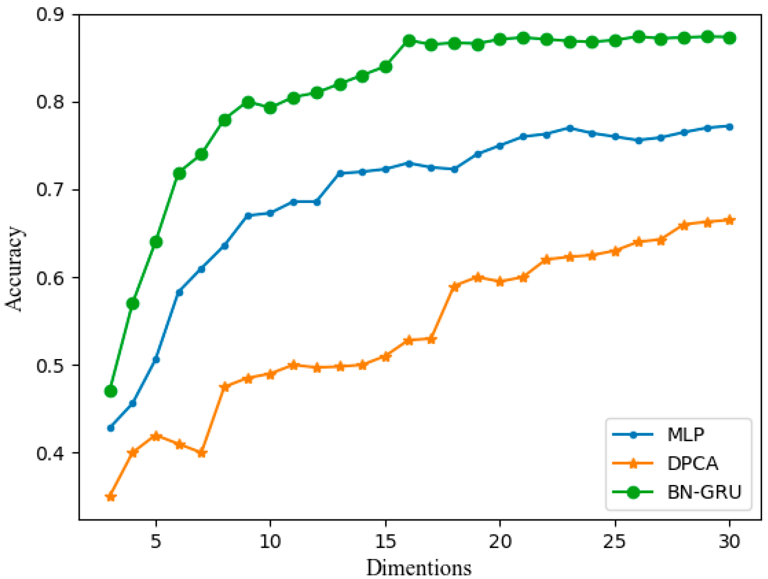
13] and for the sake of fairness, the window size for DPCA was equal to the width of the moving horizon, which was equal to 3. For DPCA, we provided the performance under different reduced dimensions (the number of principal components) from 2 to 30. We also offered the performance of MLP and BN-based GRU under a different number of nodes in the hidden layer. The MLP used in this article is a five-layer network with the same number of nodes (dimensions) per layer. The diagnosis accuracy of the three methods in different cases is shown in
Figure 9. The diagnosis accuracy shows that the proposed three-stage method based on a BN-based GRU can provide the best performance of all the methods.
We set the number of principal components of DPCA and the dimensions of the hidden layer in MLP and BN-based GRU equal to 30. The diagnosis results of DPCA-SVM are shown in
Figure 10, and the mean accuracy rate was 66.40%. The diagnosis results of MLP are shown in
Figure 11, where the mean accuracy rate was 77.23%.
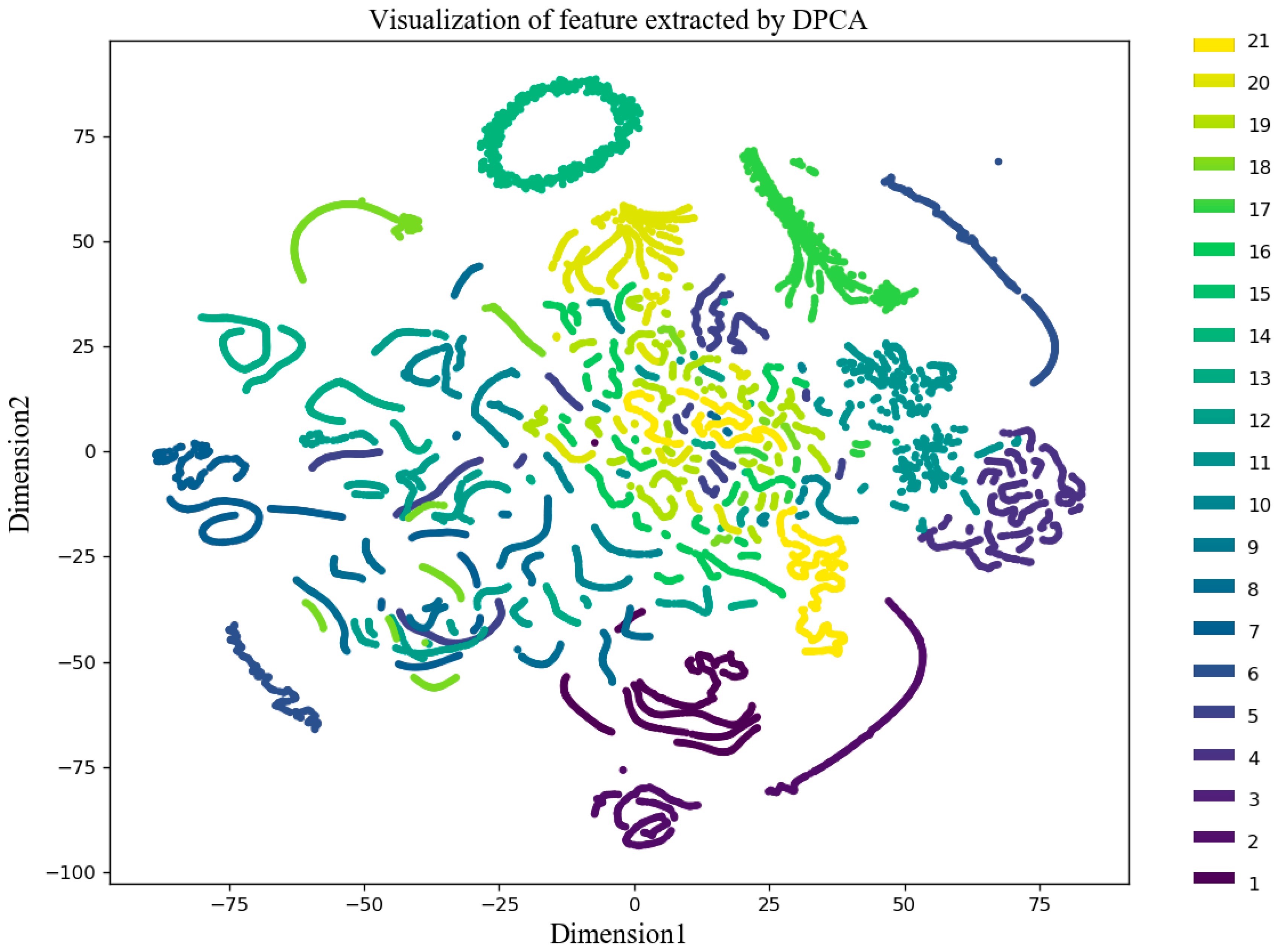
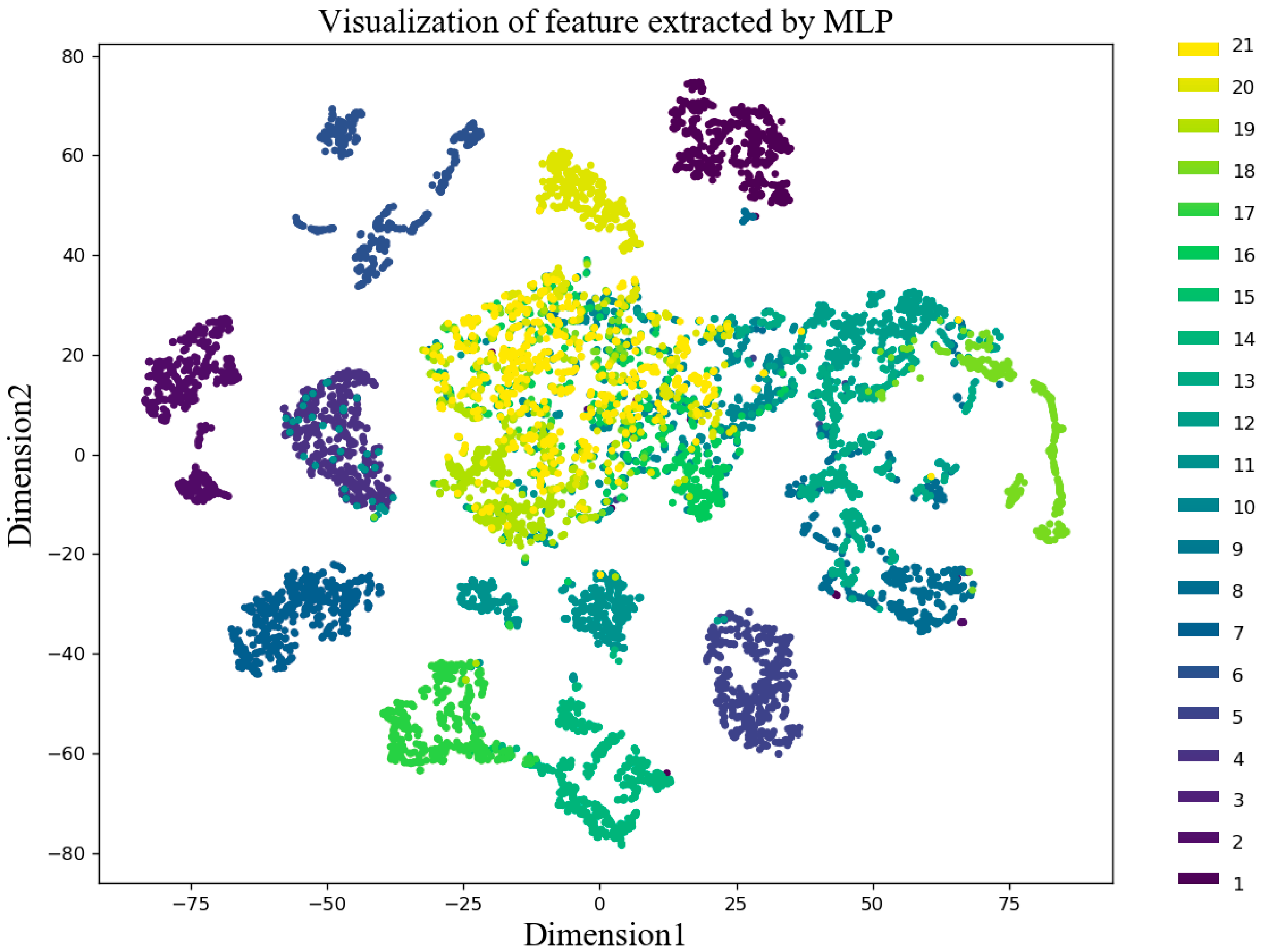
We used the dimensionality reduction technique T-distributed stochastic neighbor embedding (t-SNE) to convert the features extracted by the three algorithms into a two-dimensional (2D) image, and the resulting scatter plot is shown in
Figure 12,
Figure 13 and
Figure 14. As shown in
Figure 12, the feature extraction effect of DPCA was very poor, and only a few fault features were separated. The feature extraction effect of MLP was relatively good, and most of the fault features could be separated, but there were a few cases where, for example, faults 10, 19, 20, and 21 were confused. The fault extraction effect of a BN-based GRU was the best. Only a small part of the fault 20 and 21 were overlapping, and the rest of the features were well separated.
When dealing with data with small sizes (such as diagnosing certain types of TE faults), DPCA-SVM has considerable effects, but when dealing with large-scale data (such as diagnosing all 21 faults of TE), traditional methods like DPCA-SVM are not very effective. The GRU model of deep learning has a unique advantage in dealing with sequential data in the dynamic process. From the simulation results of the TE process, we could conclude that the proposed three-stage diagnosis method-based GRU in this paper was indeed superior to the traditional method.
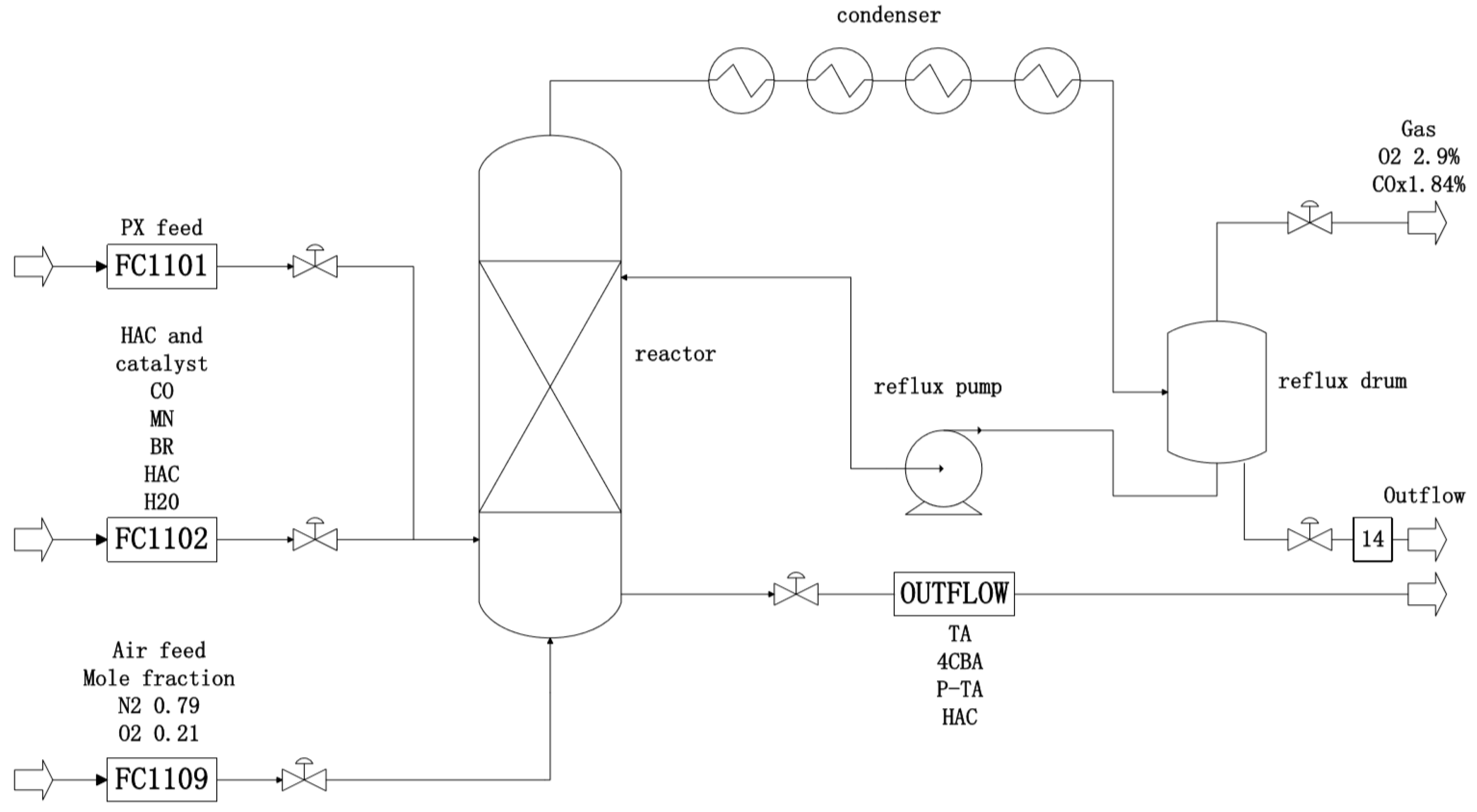
5. Case Study II: Fault Diagnosis of a PX Oxidation Process Using the Proposed Method
The PX oxidation reaction process is used for the production of PTA. There are three types of devices including one reactor, four condensers, and one reflux drum [
29,
30]. PX, acetic acid (solvent), cobalt acetate, manganese acetate (catalyst), tetrabromoethane (accelerator), and air were placed in the oxidation reactor to produce terephthalic acid (TA) in a high-temperature and high-pressure environment. [
29,
30]. The simplified flow chart of the PX oxidation process is shown in
Figure 15. A total of nine different process upsets were simulated for testing the diagnosis ability of the proposed methods, as presented in
Table 4.
5.1. Data Description
The experimental dataset was collected by the PX oxidation process involving nine different fault types. The simulation times were 10 h, and the sampling frequency was 100 times per hour. There were 1000 sets of data for each fault as the dataset. Ten percent was used as a training set and the rest as a test set. Therefore, there were a total of sets of training data and sets test data. The width of the moving horizon was also set to 10 in this experiment.
5.2. Fault Diagnosis Results and Analysis
In this experiment, the network structure and hyperparameters were as follows: the dimension of hidden state
was set to 20, and the parameters of the batch normalization algorithm
and
were set to 0. In training, the mini-batch was set to 32, the number of epochs was set to 30, the number of GRU layers was set to 1, and the width of the moving horizon was set to 3. The diagnosis results of nine faults are shown in a confusion matrix of
Figure 16a. The visualization of feature extracted using a BN-based GRU is shown in
Figure 16b. We can see that the dynamic information of the PX oxidation process data could be effectively utilized by the proposed method, and the mean testing accuracy reached 99.10%.
In actual industrial processes, labeled data is difficult to obtain. Therefore, in this experiment, we trained the network with very little data and got good results. This means that the proposed method can be applied to the fault diagnosis of dynamic processes in real industry.
5.3. Comparing with Related Work
In this case, the results of the proposed method are compared with two deep learning methods: DBN and CNN. In accordance with References [
18,
19], the neural numbers of DBN were set to
, and the CNN consisted of a pair of convolutional layer and pooling layer with a convolution kernel size of 2. The diagnosis results of DBN are shown in
Figure 17a, and the mean accuracy rate was 92.09%. The diagnosis results of CNN are shown in
Figure 17b, where the mean accuracy rate was 97.56%. From the results, it can be clearly seen that the proposed method outperformed DBN and CNN in terms of the mean accuracy, showing the potential of the proposed GRU-based fault diagnosis method.
5.4. Practical Verification
Due to the complexity of real industrial processes, the data collected is often not idealized. The existence of outliers in the training data should also be considered. In order to further verify the anti-interference ability and practicability of the proposed method, the outliers to the training data were added randomly in this case. We added 10 lots of fault 2 data in fault 1 and 10 lots of fault 5 data in fault 2 as well as fault 3.
As shown in
Figure 18, only a small number of fault 3’s were incorrectly classified as fault 5, and the diagnosis results of faults 1, 2, and 5 were unaffected. The mean accuracy remained at a high level with 98.93%. Consequently, the proposed method has practicality for real industrial processes.
6. Conclusions
In this paper, a three-stage fault diagnosis method based on a GRU neural network was proposed. In this method, we used the moving horizon to process the sequence data in the industrial process and adjusted the time step by changing the width of the moving horizon. In this way, data could be better trained using the GRU neural network. Then, we trained the GRU neural network and optimized it with the BN algorithm to reduce the influence of the covariate displacement that existed in the deep learning. The GRU neural network was relatively simple and efficient, and it could guarantee both efficiency and high accuracy when extracting the dynamic features from sequential data. Finally, softmax regression gave an accurate probability interpretation of extracted dynamic features. By optimizing the hyperparameters of the network, the proposed method solved the “curse of dimensionality” in the industrial data to a certain extent. The simulation experiment of TE data and PX oxidation process data proved that the method could effectively extract the information in the dynamic process and improved the accuracy of fault diagnosis. In addition, online data during online monitoring can be collected to update model parameters, which will further improve the accuracy. In the future, this method can be applied to more complex industrial processes. Also, a further study on dynamic information in industrial process data will be put forward.
