Article

Air-Core-Liquid-Ring (ACLR) Atomization: Influences of Gas Pressure and Atomizer Scale Up on Atomization Efficiency

Institute of Process Engineering in Life Sciences: Food Process Engineering, Karlsruhe Institute of Technology, 76131 Karlsruhe, Germany
*
Author to whom correspondence should be addressed.
Processes 2019, 7(3), 139; https://doi.org/10.3390/pr7030139
Submission received: 14 November 2018 / Revised: 21 February 2019 / Accepted: 22 February 2019 / Published: 6 March 2019

Abstract

:
Air-core-liquid-ring (ACLR) atomizers present a specific type of internal mixing pneumatic atomizers, which can be used for efficient atomization of high viscous liquids. Generally, atomization efficiency is considered as a correlation between energy input and resulting droplet size. In pneumatic atomization, air-to-liquid ratio by mass (ALR) is commonly used as reference parameter of energy input. However, the pressure energy of the atomization gas is not considered in the calculation of ALR. In internal mixing ACLR atomizers, it can be assumed that this energy contributes to liquid disintegration by expansion of the gas core after exiting the atomizer. This leads to the hypothesis that droplet sizes decrease with increasing gas pressure at constant ALR. Therefore, the use of volumetric energy density (EV) as a reference parameter of energy input was investigated at different gas pressures between 0.4 and 0.8 MPa. Furthermore, scale up-related influences on the atomization efficiency of ACLR atomization were investigated by use of an atomizer with enlarged exit orifice diameter. We can conclude that EV can be applied as a reference parameter of ACLR atomization processes with different gas pressures. However, within the range investigated no clear influence of gas pressure on atomization efficiency was found. Up-scaling of ACLR atomizers allows production of similar droplet sizes, but atomization efficiency decreases with increasing exit orifice diameter.

1. Introduction

Continuous atomization of high viscous concentrates is an important task in different industrial processes, like combustion, spray drying or coating [1,2]. In particular in spray drying, the capability to atomize high viscous feeds into small and uniform droplets is of great interest, as it allows an increase the initial dry matter content prior to actual drying [3,4].
For atomization of high viscous feeds, external-mixing pneumatic (ExMP) atomizers are commonly used [2]. In pneumatic atomizers the kinetic energy of a compressed gas stream, mostly air, is used as source of atomization energy [5,6,7]. In ExMP atomizers, gas and liquid are mixed under atmospheric conditions, outside the atomizer. As both media are supplied in separated streams, ExMP atomizers provide easy and independent control of gas and liquid flow rates [8]. Consequently, ExMP atomizers are widely used in lab and pilot scale spray drying. However, especially in spray-drying processes they do not meet the requirements of industrial applications on atomization efficiency, due to very high gas consumption rates [3,4]. In this case atomization efficiency is defined as a correlation between energy input and resulting spray droplet size. In pneumatic atomization, the energy input is typically correlated with the specific gas consumption under applied processing conditions, which is expressed as the air-to-liquid ratio (ALR) by mass (Equation (1)). Here, MX are the mass flows, Qx are volume flows and ρx are densities of gas or liquid (L).
A L R = M g a s M L = Q g a s · ρ g a s Q L · ρ L
For ExMP atomizers, ALR in a range from 1 to 10 is usually applied [1,3]. The specific atomization efficiency of an atomizer can be estimated by use of a suitable correlation function [1]. Over the years, a variety of different correlation models has been developed for all kinds of pneumatic atomizers [9]. Generic models rely on the weighting of basic parameters, like nozzle exit diameter, processing conditions and liquid properties [10,11,12]. More recent correlation functions also contain so-called nozzle constants, which can only be determined experimentally [13,14]. Consequently, related correlations can be considered as “not complete”, as additional work is required for every change of the atomizer geometry. However, nozzle constants ensure the validity of correlations for a wide range of properties and nozzle geometries. A very popular correlation function for ExMP atomizers was proposed by Harari and Sher [13] (Equation (2)).
S M D = B · ( W e · A L R ) 0.4
Here B is a characteristic nozzle constant and We is the Weber number of the gas. The Weber number represents the ratio between the air inertia forces and surface tension forces and is defined by Equation (3). In this calculation, ρgas is the gas density, Wr2 is the relative velocity, d0 is the exit orifice diameter of the nozzle and σL is the surface tension of the liquid.
W e = ρ g a s · W r 2 · d 0 σ L
In contrast to ExMP atomizers, internal mixing pneumatic (IMP) atomizers are known for high atomization efficiency, as they allow for atomization of high viscous feeds at reduced ALR [15,16,17]. Consequently, they are considered to have high potential for use in industrial spray drying [18,19]. In IMP atomizers, atomization gas and liquid stream are brought into contact in a mixing zone inside the atomizer and leave the atomizer through the exit orifice in a two-phase flow pattern. For this purpose, several gas injection geometries have been proposed (e.g., [15,17,20,21,22,23]). Although no targeted mixing of gas and liquid is performed in most cases [24], it is well known for IMP atomizers that internal flow conditions determine the means of liquid disintegration and the spray development in time and space [22]. Especially an annular flow pattern inside the exit orifice is considered to be beneficial for stable atomization results [25,26].
The air-core-liquid-ring (ACLR) atomizer was designed especially to induce an annular flow pattern in the exit orifice by injection of a continuous core of compressed gas in the middle of the liquid stream [27]. In contrast to ExMP atomizers, atomization gas gets into contact with the liquid in a compressed state. By leaving the atomizer via the exit orifice, it expands and reaches atmospheric pressure. Inside the exit orifice, gas properties depend on the specific pressure loss of the atomizer, which in turn depends on the atomizer geometry, the ALR and the viscosity of the liquid. This is mainly based on the fact that the gas and the liquid stream have to share the cross-sectional area of the exit orifice in annular flow [28]. Consequently, ALR can be increased by a decrease in liquid flow rate (QL) at constant gas pressure (pgas), or by an increase in pgas at constant liquid flow rate (QL) [29]. In the latter case, the mass flow of gas (Mgas) increases at constant volume flow (Qgas) by an increased gas density (ρgas). In practical use, this case of ALR adjustment is very important, as subsequent processes often require the adjustment of certain droplet size distributions at constant liquid flow rate and constant atomizer geometry. An increase in pgas also increases the internal energy of the atomization gas stream by means of a higher expansion potential. This additional energy might contribute to disintegration of the liquid flow into droplets. This consideration is specific to IMP atomizers. In ExMP atomizers, the influence of pgas can be neglected, as full gas expansion to atmospheric conditions can be assumed before the first contact with the gas stream. Consequently, velocities of gas and liquid are determined by atomizer geometry and ALR in ExMP atomizers. This is not the case for IMP atomizers, as the share of cross-sectional occupation of the exit orifice for liquid and gas is dependent on the pressure-dependent gas density. Accordingly, the aforementioned correlation function by Harari and Sher [13] is not applicable for IMP atomizers without knowledge of the gas pressure distribution inside the exit orifice, as the velocities of gas and liquid are unknown and change over the length of the exit orifice. As the expansion energy of the gas stream is not directly considered in the calculation of ALR (see Equation (1)) it is possible to apply equal ALR at different gas pressures with different gas expansion potentials in IMP atomizers. Based on the assumption that the energy of gas expansion contributes to the atomization energy, we hypothesize that spray droplet sizes decrease with increasing pgas at constant ALR. In this case, ALR is not sufficiently defined to represent the energy input of IMP atomizers. However, it is important to keep in mind that an increase in gas pressure is always connected to a change in gas density. Consequently, an increase in gas pressure always leads to an increase in ALR, when liquid flow rate and atomizer geometry are kept constant in IMP atomization. Therefore, it is not possible to investigate the sole influence of gas pressure on the atomization efficiency of an IMP atomizer with given geometry at constant ALR. Therefore, pgas and QL have to be increased simultaneously in a specific ratio to keep the ALR constant. Hence, the influence of pgas can only be estimated in a comparative way, using an alternative reference parameter for quantification of the energy input.
As an alternative parameter of energy input, the volume-specific energy density (EV) can be used. This parameter was originally proposed to evaluate the energy input of emulsification processes in different dispersing systems. According to Equation (4) it is defined as power input (P) per volume flow of liquid (QL) [30].
E V = P Q L
As an alternative correlation function to estimate the atomization efficiency, a characteristic droplet size xchar can be described as a function of EV by a power-law equation with two fit parameters b and c (Equation (5)) [30].
x c h a r =   c · E V b
The characteristic droplet size is mostly expressed as Sauter mean diameter (SMD). However, other characteristic values of the generated droplet size distribution can also be used, depending on the objective of the investigation. To characterize the breakup of a bulk phase at a specific energy input, the characteristic droplet size x90,3 can be used, representing the largest droplets of a distribution [31].
Stähle et al. introduced the volume specific energy density (EV) in the field of atomization, in order to compare the atomization efficiency of atomizers that use different energy sources [32]. According to the authors, this value is very useful for atomizer selection and scale up of atomization processes [32]. In contrast to the ALR, which is only applicable in pneumatic atomization, EV is defined as a discrete value (power per volume flow of processed liquid). This allows direct evaluation of energy consumptions in different atomization processes, independent of the used atomizer.
For internal mixing atomizers EV is calculated according to Equation (6), where R is the gas constant for dry air, T is the temperature, and p0 is the ambient pressure.
E V   = p g a s   +   M G   ·   R   ·   T   · ln ( p g a s + p o p o ) Q L
In contrast to the ALR, the expansion potential of the gas stream is considered in EV in form of the energy that is needed for isothermal gas compression [33]. In order to review the correlation of ALR and EV, Equations (1) and (4) can be combined. Therefore, the liquid volume flow rate (QL) is expressed as a quotient of liquid mass flow rate (ML) and liquid density (ρL). This leads to Equation (7).
E V   = p g a s   + M G M L   ·   ρ L   R   ·   T   · ln ( p g a s + p o p o )
Consequently, the mass flow ratio of gas and liquid can be replaced by the ALR (Equation (8)):
E V   =   p g a s   +   ALR   ·   ρ L   ·   R   ·   T   · ln ( 1 + p g a s p o )
Based on this correlation, it can be seen that EV increases with increasing gas pressure (pgas) at constant ALR, temperature (T) and liquid density (ρL). Therefore, as described above the increase of internal energy of the gas stream at increased pgas is considered in the calculation of EV.
Nevertheless, it is not yet clear to which extent this energy is transformed into atomization energy in ACLR atomizers. Investigations of Stähle et al. were performed at constant pgas of 0.4 MPa. To the best of our knowledge, no further work on the applicability of EV as a reference parameter of ACLR atomization efficiency has been published yet. However, it can be assumed that differences in spray droplet sizes, caused by variation of pgas at constant ALR, are reflected by the value of EV. This assumption can apply, if the portion of energy that is converted into atomization energy is larger than the energy of thermal losses. Thermal losses are not reflected by the described calculation of EV, as the energy of the gas stream is calculated on the basis of isothermal gas compression.
In order to investigate the hypothesis of decreasing droplet sizes with increasing gas pressure, we performed atomization experiments with a pilot scale ACLR atomizer at constant pgas and different QL, as well as at constant QL and different pgas. In these experiments, model solutions of different dry matter concentrations and hence different viscosities were used. From all processing conditions, ALR and EV were calculated. Thereafter, resulting droplet sizes were correlated to ALR, as well as to EV, in order to identify the applicability of both parameters as the reference of energy input in ACLR atomization. Additionally, the proposed advantages of using EV in the evaluation of scale up-related differences in atomization efficiency were investigated. As described above, energy efficiency of an ACLR atomizer depends on the pressure loss over the exit orifice, which in turn is dependent on geometry and processing conditions. Therefore, an up-scaled ACLR atomizer with larger exit orifice diameter was designed and used in atomization experiments with increased QL. Finally, the atomization efficiencies of both atomizers were compared.

2. Materials and Methods

Aqueous solutions of maltodextrin (C*Dry MD01958, Overlack GmbH, Mönchengladbach, Germany) were used as model system in the performed investigations. Dry matter contents cMD of 40, 45% and 47% were adjusted under consideration of the moisture content (X = 4.5%, dry basis) of the used maltodextrin powder. The maltodextrin solutions were characterized by viscosity (µ), surface tension (σ), density (ρ) and refractive index (RI). All measurements were executed in triplicate at a temperature of 25 °C. Mean values and relative uncertainty values ur(γ) of these parameters are summarized in dependency of the dry matter content cMD in Table 1. Viscosity measurements were performed using a rotary rheometer (MCR 101/301, Anton Paar GmbH, Graz, Austria) with coaxial cylinder geometry (CC27). Within the measurement range of shear-rates between 1 and 1000 s−1 all solutions showed Newtonian behavior. Surface tensions were measured with a Wilhelmy plate system (DCAT 21, DataPhysics Instruments GmbH, Filderstadt, Germany). For measurement of refractive indices (RI) a refractometer (Carl-Zeiss, Oberkochen, Germany) was used. Densities were measured by use of a pycnometer.

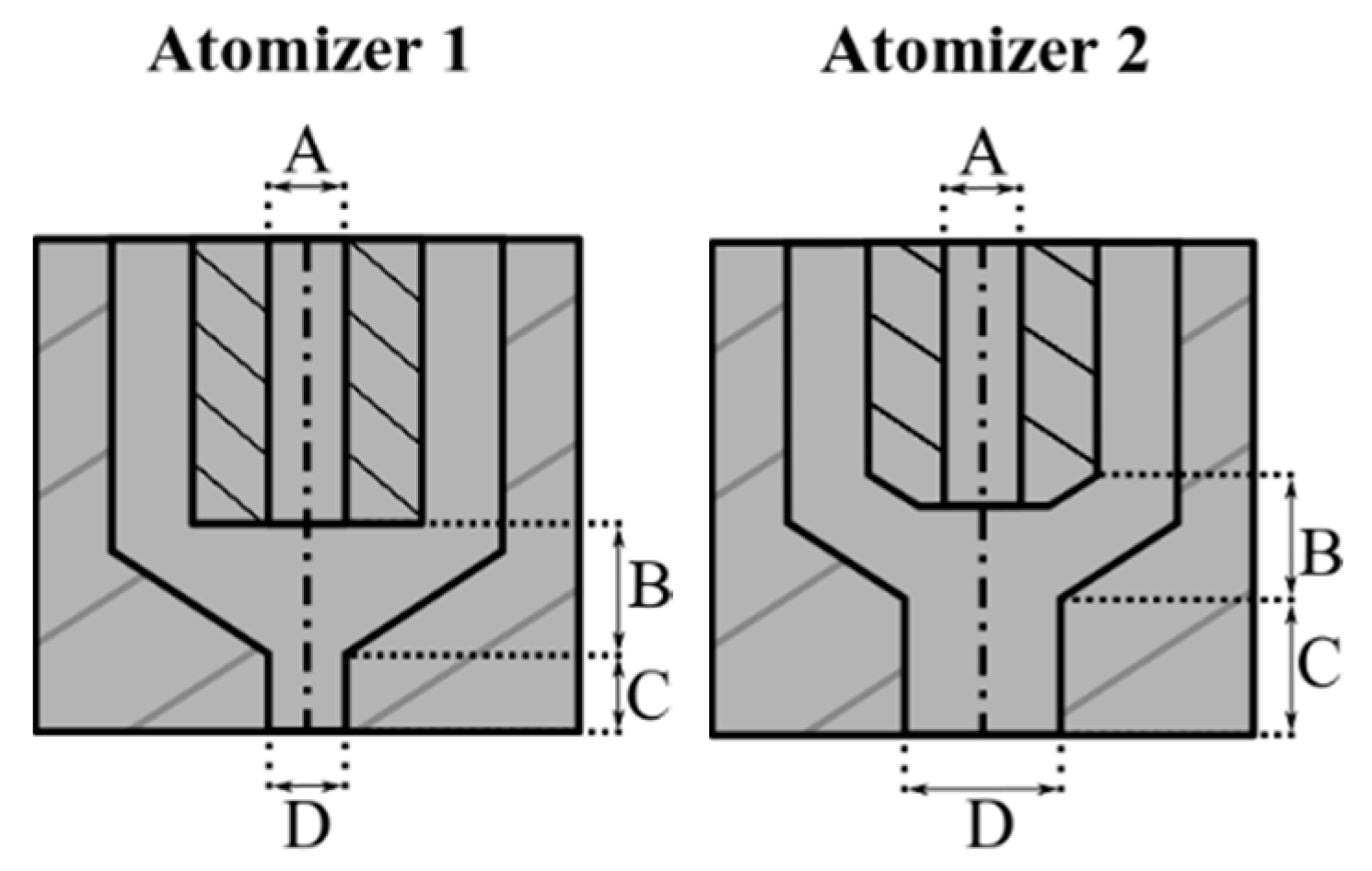
2.1. Air-Core-Liquid-Ring Atomizers

In this study, two different self-manufactured ACLR atomizers prototypes were used. The geometries of both atomizers are shown in Figure 1. Atomizer 1 is a prototype, designed for atomization in pilot scale spray-drying processes. This geometry was already used in several former studies [27,29,32,34,35,36]. Atomizer 2 is a scale up version of atomizer 1. In comparison to atomizer 1, mainly diameter and length of the exit orifice were increased. The most important dimensions of both atomizers are given in Table 2.

2.2. Spray Test Rig

For spray experiments a modular test rig was used. The atomization gas was compressed air supplied by a compressor (Renner RSF-Top 7.5, Renner GmbH, Güglingen, Germany) with a pressure vessel volume of 90 L. Relative pressures of 0.4, 0.6, and 0.8 MPa were adjusted with a pressure regulator. Corresponding gas volume flows (Qgas) were measured by a gas flow meter (ifm SD6000, ifm electronic, Essen, Germany). Measurement values of Qgas are reported at normal conditions (273.15 K, 0.1013 MPaabs) in normal cubic meters per hour (Nm3∙h−1). In experiments with atomizer 1, an eccentric screw pump (NM011BY, Erich Netzsch GmbH & Co. Holding KG, Waldkraiburg, Germany) was used for the liquid supply. The flow rate was adjusted between 21 L·h−1 and 40 L·h−1 by an electronic frequency converter. In experiments with atomizer 2, a pressure vessel was used to supply flow rates of 100 L·h−1, 120 L·h−1, and 140 L·h−1, adjusted by a manually operated needle valve. In both cases, the liquid flow rate was measured by a flow meter (VSI 044/16, VSE GmbH, Neuenrade, Germany). The liquid pressure was not monitored. All trials were performed at room temperature (25 °C).

2.3. Droplet Size Measurement

For spray droplet size measurements a laser diffraction spectroscope (Spraytec, Malvern Instruments, Malvern, UK) was mounted to the test rig. The spectroscope was equipped with a 750 mm focal lens, offering a droplet size measurement range of 2–2000 µm. The laser beam crossed the full cone of the spay angle at the atomizers centerline in a vertical distance of 250 mm. The spray was collected in a vessel below the measurement zone, which was connected to an exhaust fan. Measurements were conducted at a frequency of 250 Hz over a time of 25 s, leading to the recording of 6250 droplet size distributions per measurement. Based on this data, an average droplet size distribution was calculated under consideration of the refractive indices of the used model solutions. For beam steering correction, the method described in one of our former studies was used [36]. In this study, the commonly used Sauter mean diameter (SMD) was chosen as standard reference parameter. Additionally, the characteristic value x90,3 was regarded to review the correlation between energy input and resulting droplet sizes. This parameter represents the largest droplets of a distribution and is known to be very sensitive to changes in processing conditions of ACLR atomization. Results of x90,3 are only partly shown, in order to ensure readability of the paper.

2.4. Calculations and Statistical Analysis

OriginPro software, version 2017G (OriginLab Corporation, Northampton, MA, USA) was used for calculation of fitting curves and statistical analysis. For fitting curves, the Levenberg Marquard iteration algorithm was used. As goodness of fit parameters, the corrected determination coefficient R2 was used. The effects of ALR and EV on resulting spray droplet sizes were evaluated in dependency of the liquid viscosity by a 1-way analysis of variance (ANOVA). Scheffé’s test was used for comparison of means. In the performed tests, probability of p < 0.05 was used for the identification of significant differences.

3. Results and Discussion

3.1. Correlation between Volumetric Energy Density (EV) and Air-to-Liquid Ratio (ALR) of Applied Processing Conditions

In this section, the correlation between the standard reference parameter of energy input ALR and the potential alternative reference parameter EV for ACLR atomization is reviewed. For calculation of EV in dependency of ALR (Equation (8)), a temperature (T) of 25 °C and an atmospheric pressure (p0) of 0.1013 MPa was assumed. Liquid densities (ρL) of model solutions only vary in a small range (see Table 1). Therefore, the arithmetic mean value ρL av = 1200 kg·m−3 was used for linear prediction of the correlation between ALR and EV at constant gas pressure, based on Equation (8). These correlations are shown in Figure 2 by dashed lines. Moreover, processing conditions of performed experiments with atomizer 1 are indicated in Figure 2. For these calculations, ρL of each model solution was used. Therefore, slight differences from predictions on base of ρL av occur.
From this illustration, it can be seen that process conditions with identical ALR and different EV, as well as with identical EV and different ALR are applicable. Moreover, differences between both parameters increase with increasing pgas, as the slope of linear correlation increases. However, as the gas volume flow rate (Qgas) cannot be set independently of pgas and QL, the range of overlapping ALRs at different pgas is very small in applied processing conditions. For a detailed review of processing conditions, resulting gas volume flow rates (Qgas), as well as calculated values of ALR and EV are shown in dependency of pgas, and QL for the used model solutions (cMD, µ) in Table 3.
For each model solution, Qgas increases with decreasing QL at constant pgas. Moreover, Qgas increases at constant QL with increasing pgas, due to higher gas compression rates. Hence, ALR increases with increasing pgas at constant QL and decreases with increasing QL at constant pgas. At a viscosity of 0.39 Pa·s, ALR ranges from 0.07 (pgas = 0.4 MPa; QL = 30 L·h−1) to 0.31 (pgas = 0.8 MPa; QL = 21 L·h−1). A decrease of µ to 0.30 Pa·s leads to ALR between 0.08 and 0.31, when the aforementioned process conditions are applied. When the solution with µ = 0.12 Pa·s is used, a flow rate of QL = 40 L·h−1 at pgas = 0.4 MPa was applicable to the used pump. This leads to a decrease of the smallest ALR. The range of ALR is 0.05 to 0.35 in this case. These correlations are well known for internal mixing atomizers [1,36]. For EV, the same tendencies are present, as the same values of QL and Qgas are used for calculation. The ranges of EV are as follows: µ = 0.39 Pa·s, EV = 11.3–70.5; µ = 0.30 Pa·s, EV = 13.0–71.5; µ = 0.12 Pa·s, EV = 9.0–77.9.

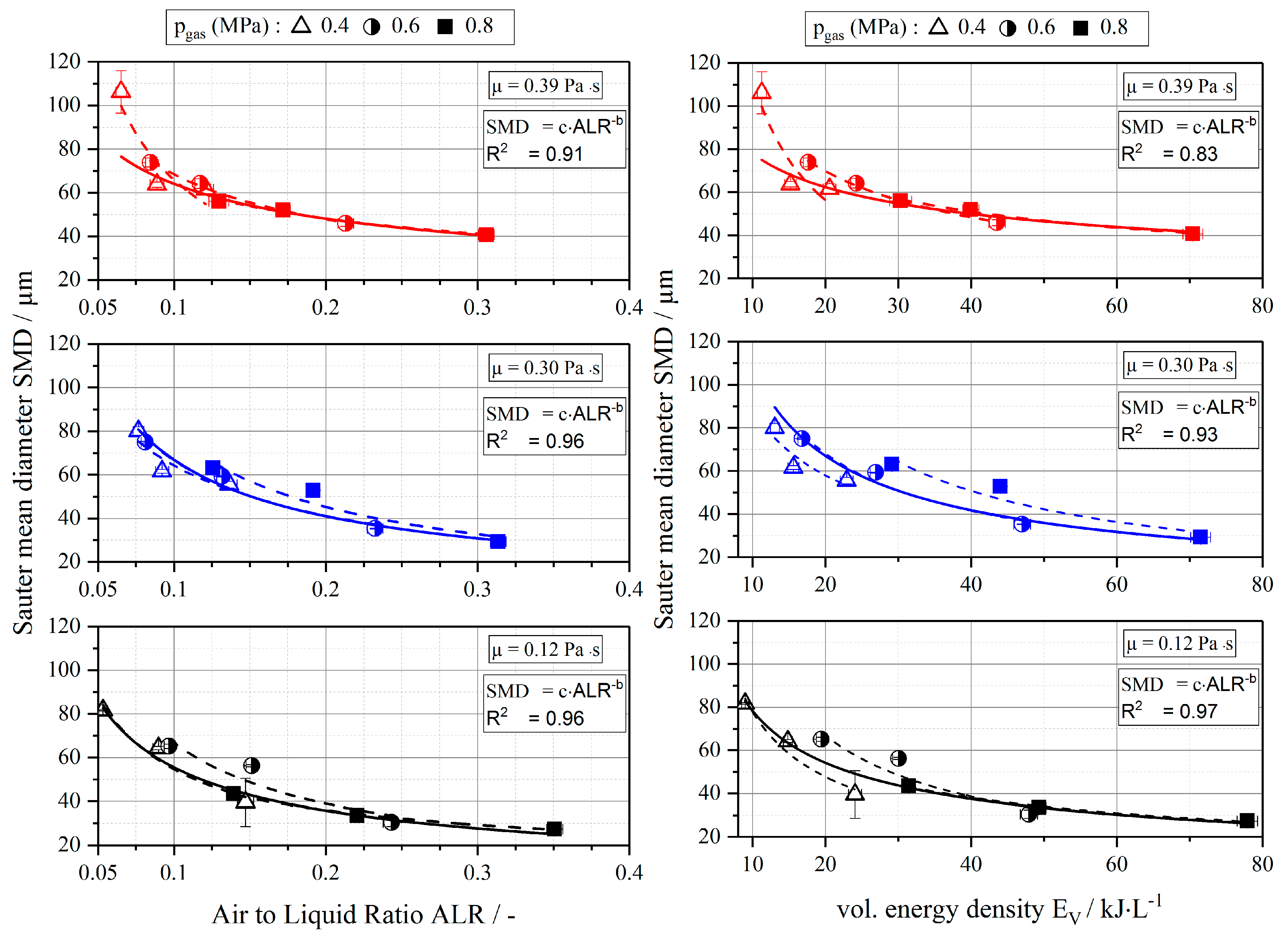
3.2. Droplet Sizes in Dependency of EV and ALR

In Figure 3, SMD is shown in the dependency of ALR (left) and EV (right). Results are presented according to the used liquid viscosity (µ): 0.39 Pa·s (red, top line), 0.30 Pa·s (blue, middle line), and 0.12 Pa·s (black, bottom line). The applied pgas is represented by different symbols: 0.4 MPa (empty), 0.6 MPa (half-filled), and 0.8 MPa (filled). Atomization efficiency is expressed by the following fit functions (Equations (9) and (10)), which are adapted from Equation (5):
SMD = c × ALR−b
SMD = c × EVb
As described above, R2 is used to review the goodness of fit. Fits of results at the same viscosity (µ) and same pgas are depicted by dashed lines. Within each fit, the level of gas compression is constant. Therefore, no differences in values of R2 are expected between applications of ALR and EV as a reference parameter, when results of same gas pressure and same viscosity are compared. Total fits of all results at same µ but different pgas are depicted by solid lines. In this case, higher R2 values are expected when EV is used as a reference parameter, as the effect of gas compression has to be represented by the applied fit. An overview of fit parameters and determination coefficients R2 is given in Table 4.
The overall dependencies between droplet sizes and both reference parameters are very similar. For all viscosities, SMD decreases with increasing energy input (ALR or EV), in a non-linear way. At low energy inputs, SMD decreases strongly with increasing energy input. With increasing energy input, this decrease is lowered. An increase in viscosity at constant energy input results in a significant increase of SMD. These tendencies are described well in literature for the correlation between ALR and SMD [20,27,37], and were also found for the correlation between energy input and the characteristic droplet size x90,3 (data not shown). At a viscosity of 0.39 Pa·s, SMD decreases from 106 µm (ALR = 0.07; EV = 11.3 kJ·L−1) to 41 µm (ALR = 0.31; EV = 70.5 kJ·L−1). Accordingly, at a viscosity of 0.30 Pa·s SMD decreases from 80 µm (ALR = 0.08; EV = 13.0 kJ·L−1) to 29 µm (ALR = 0.31; EV = 71.5 kJ·L−1). In case of a viscosity of 0.12 Pa·s SMD decreases from 81 µm (ALR = 0.05; EV = 9.0 kJ·L−1) to 27 µm (ALR = 0.35; EV = 77.9 kJ·L−1).
As expected, no significant differences in determination coefficients R2 of correlations between SMD and the both reference parameters ALR and EV are present at constant pgas (0.4, 0.6, or 0.8 MPa) and constant viscosity (0.12, 0.30, or 0.39 Pa·s) (see Table 4). The fit functions used represent well the correlations between SMD and the reference parameters over the whole range of investigated energy inputs. However, at a viscosity above 0.30 Pa·s R2 decreases from 0.99 at pgas of 0.6 MPa to 0.80 at pgas of 0.4 MPa. In this case, the deviation between the applied fit function and measurement results increases with decreasing pgas. It can be concluded that an increase in viscosity leads to a higher demand of energy input, in order to create an annular flow pattern in the exit orifice of an ACLR atomizer. Hence, pgas of 0.4 MPa might not be sufficient for the setup of a stable annular flow, at viscosities above 0.30 Pa·s. However, further research is needed to evaluate this assumption.
When all results of the same viscosity are subjected to a total fit, larger differences in R2 are present, when results for ALR and EV are compared. In the case of ALR, R2 is identical for viscosities of 0.12 and 0.30 Pa·s (0.96) and decreases to 0.90 at a viscosity of 0.39 Pa·s. In case of EV, R2 increases with increasing viscosity from 0.80 (0.12 Pa·s) to 0.92 (0.30 Pa·s) and 0.97 (0.39 Pa·s). Consequently, in case of EV the deviation between measurement points and fit equations decreases with increasing viscosity, while the deviation increases in the case of ALR with an increase in viscosity above 0.30 Pa·s.
In conclusion, the effect of gas expansion might also increase with increasing viscosity. However, within the investigated parameter range the influence of gas pressure on atomization efficiency cannot be determined to a full extent. In contrast to ALR, the expansion energy of the gas stream is considered in a calculation of EV. However, in which way and to which extent the energy contributes to droplet disintegration is not considered. Possibly, the gas core mainly expands inside the exit orifice. In this case, expansion energy would mainly be transformed into kinetic energy. Consequently, an increased gas pressure would lead to an acceleration of the gas core and, therefore, to the transmission of higher amounts of energy to the liquid sheet. In turn, this would result in a viscosity dependent decrease of the liquid sheet thickness at the end of the atomizer. Consequently, the mechanism of liquid disintegration in ACLR atomization seems to be similar to that of ExMP atomizers [38], where droplet sizes are known to decrease with decreasing liquid sheet thickness. Consequently, the direct correlation of energy input and resulting droplet sizes might not be sufficient for determination of the atomization efficiency. Instead, the liquid sheet thickness has to be taken into account for assessment of atomization efficiency, although it is difficult to evaluate in practical use. For investigation of this assumption, further studies on process dependent flow conditions inside the exit orifice of ACLR atomizers have to be carried out, in order to gain information on the relative velocity of the gas and the liquid phase. When this information is available, the correlation function for ExMP atomizers, like that proposed by Harari and Sher [13] might be applicable for ACLR atomization as well.

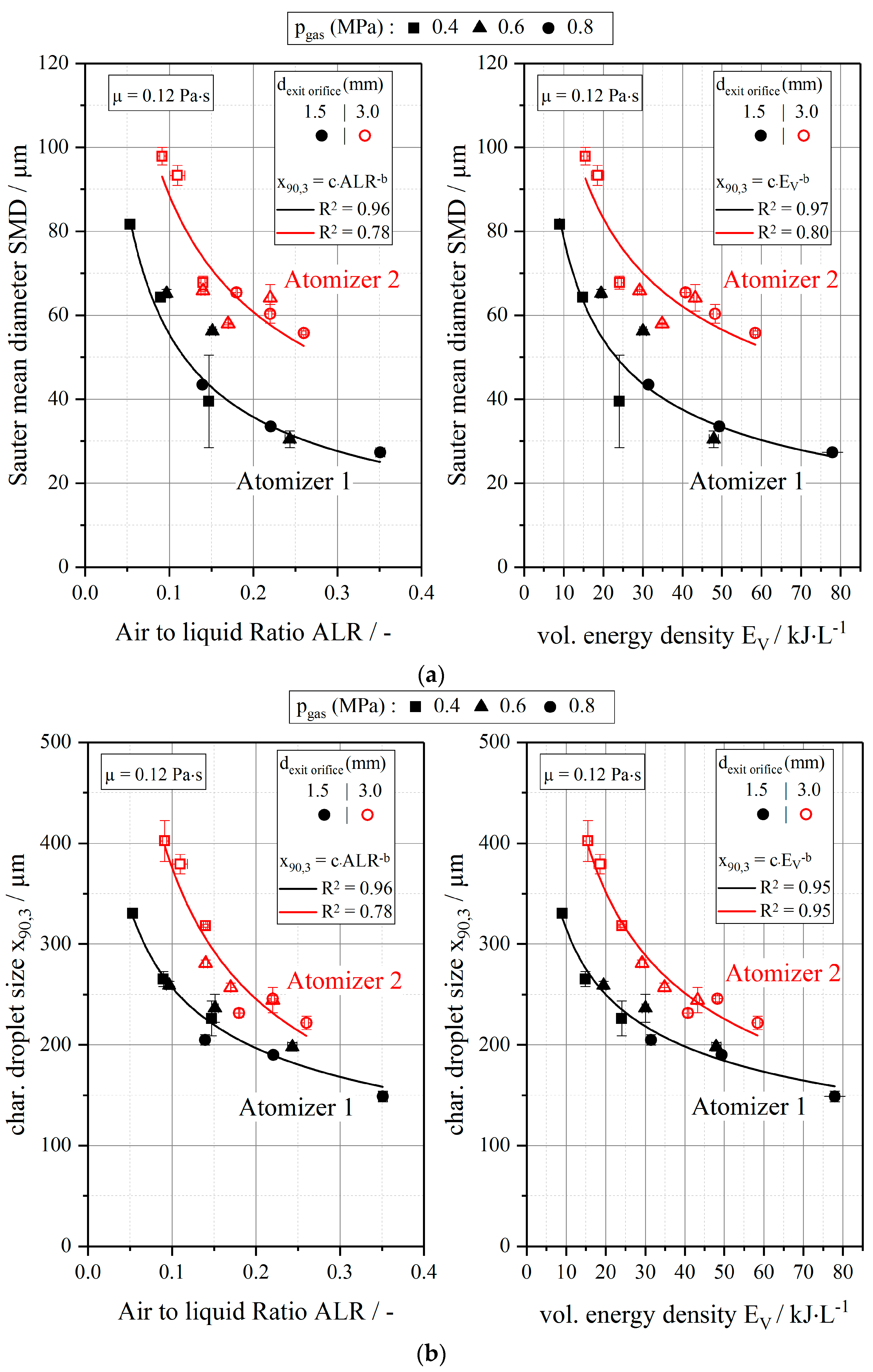
3.3. Influence of Atomizer Scale Up on Atomization Efficiency

In order to evaluate scale up-related differences in atomization efficiency, additional trials with a scaled up version of the ACLR atomizer described above were performed (atomizer 2) at µ = 012 Pa∙s. In atomizer 2, the diameter of the exit orifice (dexit orifice) was increased to 3.0 mm (see Section 2.2). Accordingly, liquid volume flow rates (QL) were increased to 100, 120, and 140 L∙h−1, while the same pgas as in the trials with atomizer 1 were applied (0.4, 0.6, and 0.8 MPa). In Table 5, gas volume flow rates (Qgas) and corresponding uncertainty values (ur(Qgas)) are shown in a dependency with QL. From this data, ALR and EV are calculated according to Equations (1) and (6). Results and corresponding uncertainty values are also presented in Table 5.
In comparison to atomizer 1, absolute values of Qgas are significantly higher, when atomizer 2 is used. However, when minimum and maximum values of both atomizers are compared, the factor of increase is in the range between 3.5 and 6.1 and, therefore, similar to the increase of QL (factor 3.5–4.8). Hence, a wide range of overlapping ALR and EV is present in the results of both atomizers. In order to review the efficiency of both atomizers, values of SMD and x90,3 are shown in dependency of ALR and EV in Figure 4a,b. Correlations between SMD and ALR, as well as between SMD and EV, are approximated according to Equations (9) and (10). Fit parameters and determination coefficients R2 are given in Table 6. Correlations between x90,3 and ALR/EV are approximated by replacing SMD by x90,3 in Equations (9) and (10). Fit parameters and determination coefficients R2 are given in Table 6.
For atomizer 2, SMD decreases from 97 µm to 56 µm with increasing energy input, while x90,3 decreases from 402 µm to 222 µm. In the case of atomizer 1, x90,3 decreases from 331 µm to 149 µm. In the correlation between SMD and ALR, R2 decreases from 0.96 to 0.78 with increasing exit diameter of the atomizer. Identical values of R2 are present for the correlation between x90,3 and ALR. For the correlation between SMD and EV, R2 decreases from 0.97 to 0.80 with increasing exit orifice diameter. When x90,3 is considered R2 of the applied fit is equal (0.95) for both atomizers. This is an interesting fact, as it can be concluded that the correlation between SMD and ALR seems to be independent of the used reference parameter. In turn, the correlation between x90,3 and EV seems to be the best choice for scale-up considerations. This might be based on the fact that x90,3 is a characteristic droplet size which is directly derived from the droplet size distribution and not a calculated mean diameter, like SMD. However, these considerations should be proved by further research.
Another interesting point is that similar values of SMD and x90,3 can be produced by both atomizers in the investigated range of energy inputs (ALR and EV). However, the necessary energy input is significantly higher for atomizer 2. Therefore, atomization efficiency decreases with increasing dexit orifice. Based on the performed approximations (see Table 6), the factor of increase averages 2.2, in order to produce the same values of x90,3. With increasing EV and, therefore, decreasing x90,3 this factor decreases from 2.6 at x90,3 = 330 µm to 1.7 at x90,3 = 210 µm. Based on these numbers, the application of several smaller atomizers would be more energy efficient than the scale up of one atomizer by increasing dexit orifice, when QL has to be increased in practical use.
In Section 3.2 it was assumed that droplet size is mainly dependent on the thickness of the liquid sheet at the end of the exit orifice and relative velocity of gas and liquid phase at constant viscosity. Assuming similar relative velocities for both atomizers at the interface between gas core and liquid sheet, also liquid sheet thickness should be similar, when same droplet sizes are produced by the two atomizers.
In the case of similar liquid sheet thickness, an increase in dexit orifice leads to an overproportional increase of the cross-sectional area, occupied by the gas core inside the exit orifice. However, the kinetic energy of the gas, travelling in the middle of the gas core, cannot be used for liquid disintegration. Therefore, a higher relative volume flow of gas is needed at increased dexit orifice, leading to higher demand of energy input and hence higher EV, when atomizer 2 is used. Still, no information on relative velocities or liquid sheet thicknesses is available at this point, which is why further investigations have to be carried out on this topic.

4. Conclusions

In the presented study, the influences of gas pressure (pgas) and atomizer scale up on atomization efficiency of air-core-liquid-ring (ACLR) atomization were investigated. It was assumed that pressure-dependent expansion energy of atomization gas contributes to liquid disintegration in ACLR atomization. For this reason it was hypothesized that droplet size decreases with increasing pgas at constant ALR. In this case ALR would not be sufficient for distinct determination of processing conditions. Therefore, the volumetric energy density (EV) was considered as an alternative reference parameter.
For correlations between SMD/x90,3 and the two investigated reference parameters of energy input, ALR and EV, only slight differences in determination coefficients R² of applied fit functions were found. In total, an influence of gas pressure on the atomization efficiency could not be determined to full extend in the range investigated. Instead, the mechanism of liquid disintegration seems to be similar to that of ExMP atomizers. Hence, resulting droplet sizes mainly dependent on the liquid sheet thickness at the outlet of the atomizer, the relative velocity of gas and liquid phase, and the viscosity of the liquid. Consequently, the use of established correlation functions for ExMP atomizers should be considered for description of the atomization performance of ACLR atomizers in future studies.
Experiments with an up-scaled ACLR atomizer revealed that similar droplet sizes can be generated with increasing liquid flow rates, when the diameter of the exit orifice is increased. However, in this case also specific energy consumption increases, leading to a decreased atomization efficiency as the kinetic energy of the gas, travelling in the middle of the gas core, cannot be used for liquid disintegration. As a conclusion, the direct correlation of energy input and resulting droplet sizes might not be sufficient for determination of atomization efficiency of differently scaled ACLR atomizers. Instead, the liquid sheet thickness has to be taken into account for assessment of atomization efficiency and scale up, although it is difficult to evaluate in practical use.
Further research will be addressed to the flow conditions inside the exit orifice of ACLR atomizers, in order to gain a better understanding of the mechanism of droplet formation. In particular, the dependency of the liquid sheet thickness and the relative velocity of gas and liquid phase has to be investigated for further development of ACLR atomization.

Author Contributions

Conceptualization, M.O.W. and V.G.; Methodology, M.O.W.; Validation, M.O.W., H.P.K. and V.G.; Investigation, M.O.W.; Writing-Original Draft Preparation, M.O.W.; Writing-Review and Editing, H.P.K. and V.G.; Visualization, M.O.W.

Funding

This research received no external funding.

Acknowledgments

The authors express their thanks to Andreas Reimer, Philip Junginger and Andrea Butterbrodt for experimental support.

Conflicts of Interest

The authors declare no conflict of interest.

References

  1. Lefebvre, A.H. Atomization and Sprays; Hemisphere Pub. Corp: Philadelphia, PA, USA, 1989; ISBN 0-89116-603-3. [Google Scholar]
  2. Ashgriz, N. (Ed.) Handbook of Atomization and Sprays; Springer: New York, NY, USA, 2011; ISBN 978-1-4419-7263-7. [Google Scholar]
  3. Masters, K. Spray Drying in Practice; SprayDryConsult International ApS: Charlottenlund, Denmark, 2002; ISBN 87-986606-08-3. [Google Scholar]
  4. Mujumdar, A.S. (Ed.) Handbook of Industrial Drying, 4th ed.; CRC Press: Boca Raton, FL, USA, 2015. [Google Scholar]
  5. Bayvel, L.P.; Orzechowski, Z. Liquid Atomization; Taylor & Francis: Washington, DC, USA, 1993; ISBN 9780891169598. [Google Scholar]
  6. Lefebvre, A.H. Airblast Atomization. Prog. Energy Combust. Sci. 1980, 6, 233–261. [Google Scholar] [CrossRef]
  7. Lefebvre, A.H. Energy Considerations in Twin-Fluid Atomization. J. Eng. Power-Trans. ASME 1992, 114, 89–96. [Google Scholar] [CrossRef]
  8. Karnawat, J.; Kushari, A. Controlled atomization using a twin-fluid swirl atomizer. Exp. Fluids 2006, 41, 649–663. [Google Scholar] [CrossRef]
  9. Omer, K.; Ashgriz, N. Spray Nozzles. In Handbook of Atomization and Sprays; Ashgriz, N., Ed.; Springer: New York, NY, USA, 2011; pp. 497–597. ISBN 978-1-4419-7263-7. [Google Scholar]
  10. Rizk, N.K.; Lefebvre, A.H. The Influence of Liquid-Film Thickness on Airblast Atomization. J. Eng. Power-Trans. ASME 1980, 102, 706–710. [Google Scholar] [CrossRef]
  11. Rizkalla, A.A.; Lefebvre, A.H. The Influence of Air and Liquid Properties on Airblast Atomization. J. Fluids Eng. 1975, 97, 316–320. [Google Scholar] [CrossRef]
  12. Jasuja, A.K. Atomization of Crude and Residual Fuel Oils. J. Eng. Power 1979, 101, 250–258. [Google Scholar] [CrossRef]
  13. Harari, R.; Sher, E. Optimization of a plain jet atomizer. At. Sprays 1997, 7, 97–113. [Google Scholar] [CrossRef]
  14. Mulhem, B.; Schulte, G.; Fritsching, U. Solid–liquid separation in suspension atomization. Chem. Eng. Sci. 2006, 61, 2582–2589. [Google Scholar] [CrossRef]
  15. Mlkvik, M.; Stähle, P.; Schuchmann, H.P.; Gaukel, V.; Jedelsky, J.; Jicha, M. Twin-fluid atomization of viscous liquids: The effect of atomizer construction on breakup process, spray stability and droplet size. Int. J. Multiph. Flow 2015, 19–31. [Google Scholar] [CrossRef]
  16. Buckner, H.J.; Sojka, P.E. Effervescent Atomization of High-Viscosity Fluids: Part I. Newtonian Liquids. At. Sprays 1991, 1, 239–252. [Google Scholar] [CrossRef]
  17. Jedelsky, J.; Jicha, M.; Slama, J.; Otahal, J. Development of an Effervescent Atomizer for Industrial Burners. Energy Fuels 2009, 23, 6121–6130. [Google Scholar] [CrossRef]
  18. Stähle, P.; Gaukel, V.; Schuchmann, H.P. Investigation on the Applicability of the Effervescent Atomizer in Spray Drying of Foods: Influence of Liquid Viscosity on Nozzle Internal Two-Phase Flow and Spray Characteristics. J. Food Process Eng. 2015, 38, 474–487. [Google Scholar] [CrossRef]
  19. Schröder, J.; Kraus, S.; Rocha, B.B.; Gaukel, V.; Schuchmann, H.P. Characterization of gelatinized corn starch suspensions and resulting drop size distributions after effervescent atomization. J. Food Eng. 2011, 105, 656–662. [Google Scholar] [CrossRef]
  20. Sovani, S.D.; Sojka, P.E.; Lefebvre, A.H. Effervescent atomization. Prog. Energy Combust. Sci. 2001, 27, 483–521. [Google Scholar] [CrossRef]
  21. Mlkvik, M.; Stähle, P.; Gaukel, V.; Zaremba, M.; Jedelský, J.; Jícha, M.; Dančová, P.; Vít, T. Performance of Twin-Fluid Atomizers for Atomization of Viscous Solutions. EPJ Web Conf. 2015, 92, 2052. [Google Scholar] [CrossRef] [Green Version]
  22. Zaremba, M.; Weiß, L.; Malý, M.; Wensing, M.; Jedelský, J.; Jícha, M. Low-pressure twin-fluid atomization: Effect of mixing process on spray formation. Int. J. Multiph. Flow 2017, 89, 277–289. [Google Scholar] [CrossRef]
  23. Zaremba, M.; Kozák, J.; Malý, M.; Weiß, L.; Rudolf, P.; Jedelský, J.; Jícha, M. An experimental analysis of the spraying processes in improved design of effervescent atomizer. Int. J. Multiph. Flow 2018, 103, 1–15. [Google Scholar] [CrossRef]
  24. Chin, J.S. Effervescent atomization and internal mixing air assist atomization. Int. J. Turbo Jet Engines 1995, 12, 119–127. [Google Scholar] [CrossRef]
  25. Shepard, T.G. Bubble Size Effect on Effervescent Atomization. Ph.D. Dissertation, University of Minnesota, Minneapolis, MN, USA, 2011. [Google Scholar]
  26. Stähle, P.; Gaukel, V.; Schuchmann, H.P. Influence of feed viscosity on the two-phase flow inside the exit orifice of an effervescent atomizer and on resulting spray characteristics. Food Res. Int. 2015, 77, 55–62. [Google Scholar] [CrossRef]
  27. Stähle, P.; Gaukel, V.; Schuchmann, H.P. Comparison of an Effervescent Nozzle and a Proposed Air-Core-Liquid-Ring (ACLR) Nozzle for Atomization of Viscous Food Liquids at Low Air Consumption. J. Food Process Eng. 2017, 40. [Google Scholar] [CrossRef]
  28. Kim, J.Y.; Lee, S.Y. Dependence of spraying performance on the internal flow pattern in effervescent atomizers. At. Sprays 2001, 11, 735–756. [Google Scholar]
  29. Wittner, M.O.; Karbstein, H.P.; Gaukel, V. Spray performance and steadiness of an effervescent atomizer and an air-core-liquid-ring atomizer for application in spray drying processes of highly concentrated feeds. Chem. Eng. Process.-Process Intensif. 2018, 96–102. [Google Scholar] [CrossRef]
  30. Karbstein, H.P.; Schubert, H. Developments in the Continuous Mechanical Production of O/W-Macro-Emulsions. Chem. Eng. Process. 1995, 34, 205–211. [Google Scholar] [CrossRef]
  31. Schuchmann, H.P.; Köhler, K.; Emin, M.A.; Schubert, H. Food Process Engineering Research and Innovation in a Fast Changing World: Paradigms/Case Studies. In Advances in Food Process Engineering Research and Applications; Yanniotis, S., Taoukis, P., Stoforos, N.G., Eds.; Springer: Boston, MA, USA, 2013; pp. 41–59. ISBN 978-1-4614-7905-5. [Google Scholar]
  32. Stähle, P.; Schuchmann, H.P.; Gaukel, V. Performance and Efficiency of Pressure-Swirl and Twin-Fluid Nozzles Spraying Food Liquids with Varying Viscosity. J. Food Process Eng. 2017, 40. [Google Scholar] [CrossRef]
  33. Walzel, P. Efficiency of the energy transformation at spray systems. In Proceedings of the 11th ILASS 1997, Florence, Italy, 9–11 July 1997. [Google Scholar]
  34. Kleinhans, A.; Georgieva, K.; Wagner, M.; Gaukel, V.; Schuchmann, H.P. On the characterization of spray unsteadiness and its influence on oil drop breakup during effervescent atomization. Chem. Eng. Process. Process Intensif. 2016, 104, 212–218. [Google Scholar] [CrossRef]
  35. Kleinhans, A.; Hornfischer, B.; Gaukel, V.; Schuchmann, H.P. Influence of viscosity ratio and initial oil drop size on the oil drop breakup during effervescent atomization. Chem. Eng. Process. Process Intensif. 2016, 109, 149–157. [Google Scholar] [CrossRef]
  36. Wittner, M.O.; Karbstein, H.P.; Gaukel, V. Pneumatic atomization: Beam steering correction in laser diffraction measurements of spray droplet size distributions. Appl. Sci. 2018, 8, 1738. [Google Scholar] [CrossRef]
  37. Konstantinov, D.; Marsh, R.; Bowen, P.J.; Crayford, A. Effervescent atomization for industrial energy-technology review. At. Sprays 2010, 20, 525–552. [Google Scholar] [CrossRef]
  38. Lefebvre, A.H. Twin-fluid atomization: Factors influencing mean drop size. At. Sprays 1992, 2, 101–119. [Google Scholar] [CrossRef]
Figure 1. Schemes of used air-core-liquid-ring atomizers 1 and 2. Dimensions of gas capillary diameter (A) and length of the mixing zone (B), as well as length (C) and diameter (D) of the exit orifice are given in Table 2.
Processes 07 00139 g001
Figure 2. Linear prediction of the correlation between EV and air-to-liquid ratio (ALR) at constant pgas and ρL av (dashed lines). Additionally, applied processing conditions are indicated: pgas = 0.4 MPa (squares), 0.6 MPa (triangles), and 0.8 MPa (circles); µ = 0.12 Pa·s (empty symbols), 0.30 Pa·s (half-filled symbols), and 0.39 Pa·s (filled symbols).
Processes 07 00139 g002
Figure 3. Characteristic droplet size Sauter mean diameter (SMD) in dependence of ALR (left) and volumetric energy density (EV) (right) for viscosities (µ) of 0.12 Pa·s (black), 0.30 Pa·s (blue), and 0.39 Pa·s (red) at pgas of 0.4 MPa (empty triangles), 0.6 MPa (half-filled circles), and 0.8 MPa (filled squares). Additionally, fits of results at the same µ and same pgas are depicted by dashed lines. Total fits of all results at the same µ and different pgas are depicted by solid lines.
Processes 07 00139 g003
Figure 4. (a). SMD in dependency of ALR (left) and EV (right) at µ = 0.12 Pa·s, using atomizers with exit orifice diameters of 1.5 mm (atomizer 1, QL = 20–40 L·h−1; black filled simbols) and 3.0 mm (atomizer 2, QL = 100–140 L·h−1; red empty symbols). Applied gas pressures are 0.4 MPa (squares), 0.6 MPa (triangles), and 0.8 MPa (circles). (b) Characteristic droplet size x90,3 in dependency of ALR (left) and EV (right) at µ = 0.12 Pa·s, using atomizers with exit orifice diameters of 1.5 mm (atomizer 1, QL = 20–40 L·h−1; black filled simbols) and 3.0 mm (atomizer 2, QL = 100–140 L·h−1; red empty symbols). Applied gas pressures are 0.4 MPa (squares), 0.6 MPa (triangles), and 0.8 MPa (circles).
Processes 07 00139 g004
Table 1. Physical properties viscosity (µ), surface tension (σ), density (ρ) and refractive index (RI), as well as corresponding uncertainty values ur(γ) of the model solutions at 25 °C. Dry matter contents cMD are given as dry base values (d.b.).
cMD (% d.b.) µ (Pa·s)ur(µ) (%)σ (N·m−1)ur(σ) (%)ρ (kg·m−3)ur(ρ) (%)RI (-)ur(RI) (%)
400.129.790.0730.0211750.021.400.07
450.305.830.0740.0612060.031.410.06
470.393.790.0740.0512180.061.420.04
Table 2. Dimensions of the used Air-core-liquid-ring (ACLR) atomizers: gas capillary diameter (A), length of the mixing zone (B), length of the exit orifice (C) and diameter of the exit orifice (D).
DimensionAtomizer 1Atomizer 2
A1.5 mm1.5 mm
B2.4 mm2.4 mm
C1.5 mm2.5 mm
D1.5 mm3 mm
Table 3. Gas pressures (pgas), liquid volume flow rates (QL), resulting gas volume flow rates (Qgas), air/liquid mass ratios (ALR) and volumetric energy densities (EV) for atomizer 1 together with the uncertainty values ur(γ) of measured/calculated parameters Qgas, ALR, and EV. Measurement values of Qgas are reported at normal conditions (273.15 K, 0.1013 MPaabs) in normal cubic meters per hour (Nm3∙h−1).
Atomizer 1
cMDµpgasQLQgasur(Qgas)ALRur(ALR)EVur(EV)
(% d.b.)(Pa∙s)(Mpa)(L·h−1)(Nm3·h−1)(%)(-)(%)(kJ·L−1)(%)
0.4212.92.010.153.5724.13.72
302.52.340.094.0814.84.15
401.92.990.055.409.05.30
214.72.130.242.2247.92.45
400.120.6304.11.400.152.5530.02.72
403.52.860.103.3719.43.44
216.82.550.351.5277.91.81
0.8306.00.960.221.6849.31.93
405.11.960.141.9931.42.18
212.70.000.143.7222.93.86
0.4252.12.710.094.6915.64.73
302.22.660.084.6213.04.64
214.61.260.232.2147.02.44
450.300.6303.71.550.132.6926.92.84
403.01.900.083.3116.83.37
216.22.480.311.6571.51.92
0.8305.52.110.191.8544.02.07
404.71.240.132.1529.12.31
212.42.370.124.1320.64.23
0.4231.92.990.095.1815.25.19
301.93.090.075.3711.35.32
214.21.360.212.3843.62.59
470.390.6303.40.000.123.0124.23.13
403.13.230.083.8717.63.88
216.10.950.311.6770.51.93
0.8305.00.000.172.6240.02.75
404.92.040.135.0430.35.04
Table 4. Fit parameters b and c, as well as determination coefficient R2 for correlations between Sauter mean diameter (SMD) and ALR, as well as between SMD and EV.
Atomizer 1
cMDµpgasSMD = c × ALR−bSMD = c × EV−b
(% d.b.)(Pa∙s)(Mpa)bcR2bcR2
400.120.40.68511.30.960.7063960.96
0.60.77611.20.900.7937200.90
0.80.50615.90.990,5142540.99
total0.63412.90.960.3211630.80
450.300.40.59716.20.800.6113610.80
0.60.69513.40.970.7115730.97
0.80.80512.40.930.82110480.93
total0.70613.20.960.6805140.92
470.390.40.9687.10.800.99411070.80
0.60.51620.80.990.5283390.99
0.80.37826.20.990.3842100.99
total0.41324.70.900.5312650.97
Table 5. Applied gas pressures (pgas) and liquid volume flow rates (QL), as well as resulting gas volume flow rates (Qgas), air/liquid mass ratios (ALR) and volumetric energy densities (EV). Additionally, uncertainty values ur(γ) of resulting parameters Qgas, ALR, and EV are given. Measurement values of Qgas are reported at normal conditions (273.15 K, 0.1013 MPaabs) in normal cubic meters per hour (Nm3∙h−1).
Atomizer 2
cMDµpgasQLur(QL)Qgasur(Qgas)ALRur(ALR)EVur(EV)
(% d.b.)(Pa∙s)(Mpa)(L·h−1)(%)(Nm3·h−1)(%)(-)(%)(kJ·L−1)(%)
400.120.41000.2113.22.000.141.8524.12.01
1200.8212.07.360.118.0518.68.36
1410.4811.73.080.092.7815.52.71
0.61000.6319.60.880.220.9243.30.92
1200.0518.90.030.170.0734.90.07
1400.6818.41.130.141.7629.21.89
0.81000.6624.00.240.260.8758.40.91
1200.4623.50.650.220.9048.20.91
1400.2222.90.250.180.4740.80.46
Table 6. (a) Fit parameters b and c, as well as determination coefficient R2 for correlations between SMD and EV. (b) Fit parameters b and c, as well as determination coefficient R2 for correlations between x90,3 and EV.
(a)
cMDµAtomizerdexit orificeSMD = c × ALR−bSMD = c × EV−b
(% d.b.)(Pa∙s)-(mm)bcR2bcR2
400.1211.50.63412.90.960.5312660.97
23.00.54425.30.780.4202930.80
(b)
cMDµAtomizerdexit orificex90,3 = c·× ALR−bx90,3 = c × EV−b
(% d.b.)(Pa∙s)-(mm)bcR2bcR2
400.1211.50.387105.60.940.334680.70.95
23.00.61591.20.900.4851502.60.95

