Article

Heat Transfer Enhancement by Coupling of Carbon Nanotubes and SiO2 Nanofluids: A Numerical Approach

1
Department of Mathematics, Faculty of Sciences, HITEC University Taxila Cantt, Rawalpindi 47080, Pakistan
2
Department of Mathematics, COMSATS University Islamabad, Islamabad 45550, Pakistan
3
Department of Mathematics and Statistics, Hazara University, Mansehra 21120, Pakistan
4
Department of Mathematics and Social Sciences, Sukkur IBA University, Sukkur 65200, Pakistan
5
Center of Excellence for Research in Engineering Materials (CEREM), King Saud University, P.O. Box 800, Al-Riyadh 11421, Saudi Arabia
6
Electrochemistry and Corrosion Laboratory, Department of Physical Chemistry, National Research Centre, El-Behoth St. 33, Dokki, Cairo 12622, Egypt
7
Faculty of Mathematics and Statistics, Ton Duc Thang University, Ho Chi Minh City 72915, Vietnam
*
Author to whom correspondence should be addressed.
Processes 2019, 7(12), 937; https://doi.org/10.3390/pr7120937
Submission received: 22 October 2019 / Revised: 2 December 2019 / Accepted: 3 December 2019 / Published: 9 December 2019
(This article belongs to the Special Issue Fluid Flow and Heat Transfer of Nanofluids)

Abstract

:
This article comprises the study of three-dimensional squeezing flow of (CNT-SiO2/H2O) hybrid nanofluid. The flow is confined inside a rotating channel whose lower wall is stretchable as well as permeable. Heat transfer with viscous dissipation is a main subject of interest. We have analyzed mathematically the benefits of hybridizing SiO 2 -based nanofluid with carbon nanotubes ( CNTs ) nanoparticles. To describe the effective thermal conductivity of the CNTs -based nanofluid, a renovated Hamilton–Crosser model (RHCM) has been employed. This model is an extension of Hamilton and Crosser’s model because it also incorporates the effect of the interfacial layer. For the present flow scenario, the governing equations (after the implementation of similarity transformations) results in a set of ordinary differential equations (ODEs). We have solved that system of ODEs, coupled with suitable boundary conditions (BCs), by implementing a newly proposed modified Hermite wavelet method (MHWM). The credibility of the proposed algorithm has been ensured by comparing the procured results with the result obtained by the Runge-Kutta-Fehlberg solution. Moreover, graphical assistance has also been provided to inspect the significance of various embedded parameters on the temperature and velocity profile. The expression for the local Nusselt number and the skin friction coefficient were also derived, and their influential behavior has been briefly discussed.

1. Introduction

Over a past few decades, nanofluid has displayed unprecedented potential applications in many disciplines, including microelectronics, microfluidics, transportation, biomedical circuits, optical devices, industrial cooling applications, aerospace, nuclear cooling systems, automotive sector, chemical, and electrical engineering. The ongoing research in this area, highlights the improvement of the thermo-mechanical and tribological features of the fluid, on the macroscopic and microscopic level. Therefore, scientists have finally achieved a staggering level of progress in reducing the friction effects and enhancing the thermal properties like conductivity, diffusivity, and convective heat transfer coefficients of nanofluid, as compared to those of traditional fluids like water and oil. Choi and his fellow workers [1,2], deserve credit for introducing the concept of nanofluid. Later, their efforts were followed by many researchers and consequently, a number of theoretical and experimental studies have been accomplished. Priorly, a theoretical model has been suggested by Maxwell [3], which encounters the suspensions comprising spherical shaped nanostructures. This model effectively predicts an enhancement in the thermal conductivity of nanofluid via augmenting the nanoparticles volume fraction. Lately, Hamilton and Crosser [4], came up with a modified version of Maxwell’s model, which demonstrated the influence of particle shape and volume fraction, on the thermal efficiency of the fluid containing nanometer sized structures. Further studies have exposed a diverse class of models, which incorporates different features of nanomaterials, like Brownian motion [5], nanoparticles size [6,7], shapes [8], liquid layering [9], and particles agglomeration [10,11], in order to examine the variations in thermo-physical characteristics of nanofluid.
The discovery of the fullerene structural family, opens the avenue for research, by considering cylindrically shaped nanomaterials, entitled as carbon nanotubes (CNTs). These carbon-based nanotubes were invented by Japanese scientists “Iijima” in 1991 [12]. Their novel properties exhibit enormously exciting applications in various fields like chemical engineering, electronics, mechanical engineering, optical devices, absorption, catalytic, transport systems, nanotechnology, and other disciplines of material sciences [13,14]. They are classified into two groups; single-walled carbon nanotubes (SWCNTs) and multi-walled carbon nanotubes (MWCNTs). Single-walled carbon nanotubes comprise of a single tube, which keep millions of atoms together, whereas, multi-walled carbon nanotubes are a cluster of nested tubes with incessantly growing diameter. The research community diverts their attention towards the study of carbon nanotubes, due to its remarkable thermal characteristics. Several models have been successfully proposed, to predict the thermal efficiency of carbon nanostructures. By employing the average theory of polarization, Xue et al. [15] presented a model, which studies the influence of interface interaction between the bulk liquid and the CNTs. Murshed et al. [16] suggested a model which incorporates the effect of interfacial layer and thickness around the CNT, to analyze the heat-conducting effects in the radial direction of CNTs. In 2017, Yang and Xu [17] introduced a renovated Hamilton–Crosser model (RHCM), which effectively predicts the thermal conductivity of nanofluid engineered by dispersing CNTs. This model usually studies the consequences of aspect ratio and CNTs diameter along with the interfacial layer. A number of model-based scientific studies can also be found [18,19,20].
The unique features of nanofluids have caught the eye of many researchers, to produce the new thermally efficient systems, for various engineering disciplines. Mono nanofluids, engineered by dispersing a single kind of nanocomposites, ascertain some specified properties of the suspended nanomaterials. However, to enhance the basic properties of nanofluids, that can certainly endorse specific characteristics, scientists discovered an updated version of heat transfer fluid, named as hybrid nanofluid. This hybrid composition can be accomplished, either by dispersing nanomaterials of a dissimilar nature or by scattering nanometer sized composite structures within the host fluid. The thermal network and physio-chemical properties of the hybrid nanofluid may be augmented by the synergistic effects [21]. Hybrid nanofluids paved a pathway in various heat management applications such as nuclear system cooling, engine cooling, automobile radiators, generator cooling, coolant in machining, electronics cooling, welding, lubrication, solar heating, biomedical, drug reduction, thermal storage, refrigeration, and defense [22].
The worldwide researchers, to investigate the merits, demerits, and their applicability in various disciplines, eagerly began to study the behavior and salient features of hybrid nanofluids. By considering an innovative concept of material design, Niihara [23] inspected the variations in thermo-mechanical characteristics of the carrier fluid, by taking into account a variety of nanoparticles. Jana et al. [24] considered the single and hybrid composition of nanomaterials, to investigate the enhancement in the thermal conductivity of the carrier fluid. A two-step process has been employed by Suresh et al. [25], to discuss the synthesis of water-based ( AI 2 O 3 - Cu ) hybrid nanofluid. They have experimentally reported the variations in the thermal and rheological characteristics of the hybrid nanofluid. In continuation to the previous study, they have examined the consequences of ( AI 2 O 3 - Cu ) hybrid nanofluid on the convective heat transfer rate [26]. By opting for a procedure of functionalization, Abbasi et al. [27] explored the heat management characteristics and dispersion behavior of ( MWCNT / γ AI 2 O 3 ) hybrid nanofluid. The augmentation in the physio-chemical properties, like viscosity and thermal conductivity of water based ( MWCNT - Fe 3 O 4 ) hybrid nanofluid have been comprehensively discussed by Sundar et al. [28]. Hemmat Esfe et al. [29] reported the influential behavior of water based ( CNT - AI 2 O 3 ) hybrid nanofluid, with the varying solid volume fraction and temperature distribution. Devi and Devi [30] opted for a numerical procedure, for magneto hydrodynamic flow of H 2 O based ( Cu - AI 2 O 3 ) hybrid nanofluid over a stretchable porous surface. The readers can also explore a number of studies related to this subject in [31,32,33,34].
The enormously exciting applications of the fluid flowing inside a channel exhibiting a squeezed wall motion have gained the fancy of scientists worldwide. They have paved a way in various industrial and physical processes such as food industry, biomechanics, polymer processing, the formation of lubrication, automotive engines, bearings, appliances, and blood flow in vessels due to dilation and contraction. They have also been found in certain disciplines of engineering like mechanical, electrical and chemical engineering. The study relevant to the subject of squeezing flows was initiated in the 19th century. Stefan [35] was the pioneer behind this rudimentary work. He procured, an asymptotic solution for the squeezed flow of viscous compressible fluid. Later on, in the 20th century, many researchers started to analyze the squeezing flows in different geometries. The studies conducted by Langlois [36] followed by Salbu [37], displayed the behavior of a squeezed film flow, by excluding the inertial phenomena. Thorpe [38] studied the influential behavior of squeezed flow, under the action of inertial forces and determined an explicit solution for the relevant problem. Munawar et al. [39] investigated the three-dimensional fluid flow along with the rotatory channel. They have considered a permeable lower wall, which also exhibits a stretching velocity. Later on, Butt and Ali [40] analyzed the influence of entropy generation on the geometry proposed by Munawer et al. [39]. Khan et al. [41], extended the work of [40], by taking into account a CNTs based nanofluid. Quite recently, Ghadikolaei et al. [42], also employed the geometry of [40] and discussed the influence of shape factors along with thermal radiation, on the ethylene glycol-water based ( Fe 3 O 4 - Ag ) hybrid nanofluid.
During the literature review, no single attempt has been found, regarding the study of heat transfer enhancement by the coupling of CNTs and ( SiO 2 / H 2 O ) nanofluid, i.e., (CNT-SiO2/H2O) hybrid nanofluid, inside a three-dimensional rotatory channel, whose upper wall exhibits a squeezing motion, while the lower one is permeable and capable of being stretched. It has numerous practical and theoretical relevance in engineering, industries, and geophysics like in the food and chemical process industry, ground and air conveyance automobiles, rotating machines, industrial plants, and centrifugal filtration processes. Therefore, this study encompasses a detailed analysis of the problem as mentioned earlier. A new correlation, for thermal conductivity of (CNT-SiO2/H2O) hybrid nanofluid, has been developed by employing two different models; the Maxwell model and a renovated Hamilton–Crosser model, which can simultaneously predicts the thermal conductivities of SiO 2 and CNTs . Moreover, the governing transformed set of ordinary differential equations (ODE) coupled with suitable BCs, are then handled via the modified Hermite wavelet method (MHWM). The procured results are then compared with the Runge-Kutta (order-4). This comparability and the error estimation, therefore, lead to the credibility of the proposed algorithm. Moreover, the graphical assistance along with a detailed discussion has been provided in Section 5, in order to check the influence of various emerging parameters on the velocity and temperature profiles. We are hopeful that the numerical outcomes of this study will help in designing the effective system of cooling of many electrical rotating machines.

2. Formulation of Governing Equations

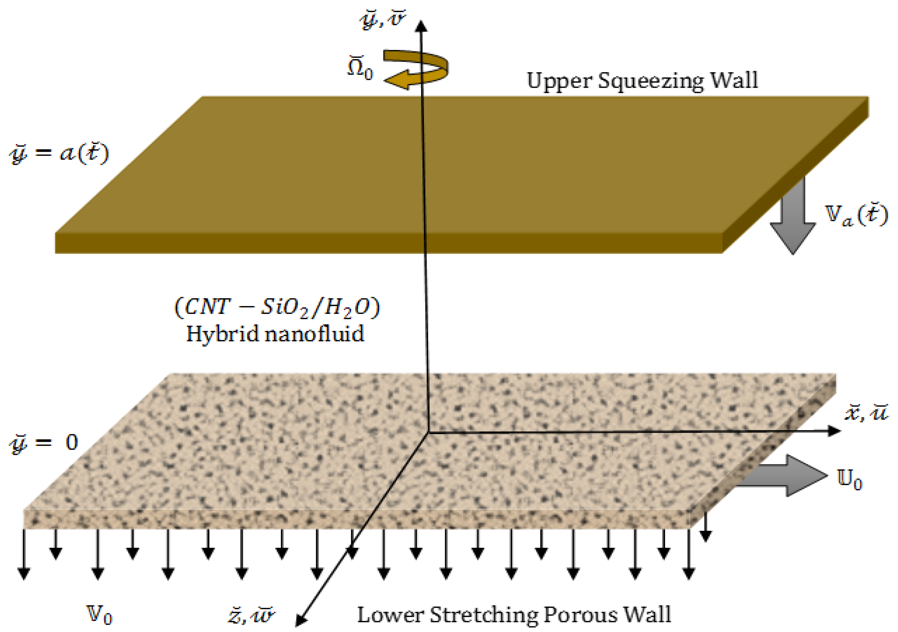
A 3D channel comprising infinite long parallel plates has been under consideration, which confines a rotatory flow of (CNT-SiO2/H2O) hybrid nanofluid. The fluid is also supposed to be viscid, incompressible, and time-dependent. The hybrid composition has been accomplished by dispersing CNTs with different volume fractions into 0.1 vol . (which remains fixed for the present flow situation) of ( SiO 2 / H 2 O ) nanofluid. The gap between both the plates is a ( t ˘ ) , so its hydraulic diameter is a ( t ˘ ) . Since the flow is assumed to be laminar, so R e < 2300 . Furthermore, the assumptions, for the present flow situation, are enlisted as [40]:
  • The lower wall, situated at y ˘ = 0 , experiences a time-dependent stretching velocity 𝕦 0 = c x ˘ / ( 1 κ t ˘ ) in the horizontal direction.
  • The channel’s upper wall occupies the place at a variable distance y ˘ = a ( t ˘ ) = ( c / ( 1 κ t ˘ ) υ f ) 0.5 and also exhibit a time-dependent squeezing velocity V a = d a / d t ˘ , whose direction is opposite to the positive y ˘ -direction.
  • Besides, it is also assumed that the wall, at the lower extremity of the channel, is permeable and the velocity with which fluid is sucked, is given as V 0 / ( 1 κ t ˘ ) .
  • The channel along with the fluid confined between the parallel plates turns around the y ˘ axis with the angular velocity Ω ˘ = Ω ˘ 0 J ^ / ( 1 κ t ˘ ) .
  • The temperatures of the stretching wall at the lower side and the squeezing wall at the upper side of the channel are respectively denoted by T ˘ 0 and T ˘ a , along with the assumption that T ˘ a < T ˘ 0 . Figure 1 demonstrates the physical model of the present flow situation.
Keeping in view the assumptions mentioned above, the present flow and heat transfer phenomenon, subject to the rotating frame of reference, can be deliberated through the subsequent equations [40]:
v ˘ y ˘ + u ˘ x ˘ = 0 ,
p ˘ x ˘ + ρ ˘ h n f ( u ˘ t ˘ + u ˘ x ˘ u ˘ + u ˘ y ˘ v ˘ + 2 Ω ˘ 0 1 κ t ˘ w ˘ ) = μ h n f ( 2 u ˘ y ˘ 2 + 2 u ˘ x ˘ 2 ) ,
p ˘ y ˘ + ρ ˘ h n f ( v ˘ t ˘ + v ˘ x ˘ u ˘ + v ˘ y ˘ v ˘ ) = μ h n f ( 2 v ˘ y ˘ 2 + 2 v ˘ x ˘ 2 ) ,
ρ ˘ h n f ( w ˘ t ˘ + w ˘ x ˘ u ˘ + w ˘ y ˘ v ˘ 2 Ω ˘ 0 1 κ t ˘ u ˘ ) = μ h n f ( 2 w ˘ y ˘ 2 + 2 w ˘ x ˘ 2 ) ,
( ρ ˘ C p ) h n f ( T ˘ t ˘ + T ˘ x ˘ u ˘ + T ˘ y ˘ v ˘ ) = K h n f ( 2 T ˘ y ˘ 2 + 2 T ˘ x ˘ 2 ) + μ h n f { ( w ˘ y ˘ ) 2 + 4 ( u ˘ x ˘ ) 2 + ( w ˘ x ˘ ) 2 + ( v ˘ x ˘ + u ˘ y ˘ ) 2 }
where, u ˘ , v ˘ , and w ˘ represents the velocity components along x ˘ , y ˘ , and z ˘ direction respectively. p ˘ and T ˘ denotes the dimensional pressure and temperature of the fluid. Moreover, κ indicates the characteristic parameter, which holds the dimension of ( time ) 1 , and 1 > κ t ˘ .
The boundary conditions that specify the current flow situation is given as [40]:
u ˘ = 𝕦 0 = c x ˘ 1 κ t ˘ , v ˘ = V 0 1 κ t ˘ , w ˘ = 0 , T ˘ = T ˘ 0 , at y ˘ = 0 ,
v ˘ = V a = κ 2 ( c ( 1 κ t ˘ ) υ f ) 0.5 , w ˘ = 0 , u ˘ = 0 , T ˘ = T ˘ a , at y ˘ =   a ( t ˘ ) ,
where, T ˘ 0 and T ˘ a simultaneously indicate the temperatures of the plates situated at y ˘ = 0 and y ˘ = a ( t ˘ ) . Moreover, c > 0 is the constant, which indicates the stretching rate of the surface placed at y ˘ = 0 .
In the preceding set of Equations (1)–(5), the effective density [30] and the dynamic viscosity [30] of the hybrid nanofluid are simultaneously represented by ρ ˘ h n f and μ h n f , which significantly influences the flow properties of the host fluid. Moreover, ( ρ ˘ C p ) h n f specifies the heat capacity [30] of the (CNT-SiO2/H2O) hybrid nanofluid. Mathematically:
μ h n f = ( 1 φ 1 ) 5 / 2 ( 1 φ 2 ) 5 / 2 μ f ,
ρ ˘ h n f ρ ˘ f = [ { 1 + φ 1 ( ρ ˘ p 1 ρ ˘ f 1 ) } ( 1 φ 2 ) + ρ ˘ p 2 ρ ˘ f φ 2 ] ,
( ρ ˘ C p ) h n f ( ρ ˘ C p ) f = [ 1 + φ 1 ( ( ρ ˘ C p ) p 1 ( ρ ˘ C p ) f 1 ) ] ( 1 φ 2 ) + ( ρ ˘ C p ) p 2 ( ρ ˘ C p ) f φ 2 ,
where, μ f , ρ ˘ f , and ( ρ ˘ C p ) f denotes the effective viscosity, density and specific heat of the host fluid (water), respectively.
Thermal conductivity ( K h n f ) of a substance is one of the basic properties that encounters the rate of heat flux by conduction. The models, prescribed for the thermal conductivity of nanofluid engineered by dispersing CNTs, are usually less in number compared to those nanofluids, which involve the spherical-shaped nanoparticles. In 2017, Yang and Xu [1] introduced a renovated Hamilton–Crosser model, which effectively predicts the thermal conductivity of nanofluid engineered by dispersing CNTs. This model usually incorporates the consequences of aspect ratio and CNTs diameter along with the interfacial layer. By following the mixture principle, this model can also be employed to estimate the thermal efficiency of (CNT-SiO2/H2O) hybrid nanofluid. Mathematically, it can be expressed as:
K h n f = K b f K p e + ( n 1 1 ) K b f ( n 1 1 ) ( 1 + C ) ( K b f K p e ) φ 2 K p e + ( n 1 1 ) K b f + ( 1 + C ) ( K b f K p e ) φ 2 , n 1 = 3 ψ g , K p e = 1 π 0 π K p e z 2 sin 2 α + K p e x 2 cos 2 α d α , K p e x = A K p 2 φ 2 + C K r φ 2 A φ 2 + C φ 2 , K p e z = K p 2 + C K r 1 + C , K r = K p 2 [ 𝕥 + ( 1 K b f / K p 2 ) ] l n [ ( 𝕥 / ) + 1 ] 𝕥 K b f l n [ { ( 𝕥 / ) + 1 } K p 2 / K b f ] , A = 2 K r K p 2 + K r , = + 𝕥 ( K p 2 K r K p 2 + K r 1 ) , C = ( + 𝕥 ) 2 2 2 , ψ = 2 e ( 𝕦 ) [ 1 e 2 ( 𝕦 ) ] 1 / 6 e ( 𝕦 ) 1 e 2 ( 𝕦 ) + sin 1 ( e ( 𝕦 ) ) , e ( 𝕦 ) = 1 ( 2 + 𝕦 ) ( ( / 2 ) 2 + 𝕦 ) .
where, n 1 represents the empirical shape factor, which depends upon the sphericity ψ and the empirical parameter g . Yu and Choi [18,19] followed by Jiang et al. [20], through their studies, found that this parameter g should be equal to 1.55 for CNTs based nanofluids. e ( 𝕦 ) denotes the eccentricity. and indicates the length and radius of the CNTs, respectively, with the assumption > . Moreover, the interfacial layer thickness around the CNTs is symbolized by 𝕥 and is set as 2 n m for the present flow model. The thermal conductivity of the CNT/layer composites in the radial direction is represented by K p e x , while K p e z denotes the same in the axial direction. K r elucidates the thermal conductivity of the interfacial layer around the CNTs and its mathematical expression was reported by Jiang et al. [20]. The thermal conductivity of the (CNT-SiO2/H2O) hybrid nanofluid is symbolized by K h n f , while, K b f illustrates the thermal conductivity of the ( SiO 2 / H 2 O ) nanofluid, which can be defined by the Maxwell correlation [4,30]:
K b f = K f K p 1 + 2 K f 2 φ 1 ( K f K p 1 ) K p 1 + 2 K f + φ 1 ( K f K p 1 ) .
Furthermore, the thermal conductivities of SiO 2 and CNT nanocomposites are denoted by K p 1 and K p 2 , respectively. K f represents the thermal conductivity of the host fluid ( H 2 O ) . Moreover, φ 1 symbolizes the volume fraction for SiO 2 tiny particles, while the solid volume fraction for CNTs is given by φ 2 . Table 1 has been fabricated with the thermo-physical properties of the carrier fluid ( H 2 O ) and the nanomaterials ( SiO 2 and CNTs ) .
The system of Equations (1)–(5) along with the boundary conditions of Equations (6) and (7), may be brought into non-dimensional form by taking the following similarity transforms into account [40]:
u ˘ = 𝕦 0 ˘ ( χ ) , v ˘ = ( 1 κ t ˘ c υ f ) 0.5 ˘ ( χ ) , w ˘ = 𝕦 0 G ˘ ( χ ) , χ = ( a ( t ˘ ) y ˘ ) 1 , Θ ˘ ( χ ) = T ˘ T ˘ a T ˘ 0 T ˘ a .
Under the group of transformation as described above, the set of Equations (2)–(5) can take the following non-dimensional form:
˘ i v Y ˘ 1 [ 1 ( Y ˘ 2 ) 1 { ˘ ˘ ˘ ˘ + 2 ϖ 0 G ˘ + S q 2 ( χ ˘ + 3 ˘ ) } ] = 0 ,
G ˘ + Y ˘ 1 [ 1 ( Y ˘ 2 ) 1 { ˘ G ˘ ˘ G ˘ + 2 ϖ 0 ˘ S q ( G ˘ + χ 2 G ˘ ) } ] = 0 ,
( K h n f K f Θ ˘ ) + Pr Y ˘ 3 ( ˘ S q 2 χ ) Θ ˘ + Pr Y ˘ 1 [ Ε c ( 4 ˘ 2 + G ˘ 2 ) + Ε c x ˘ ( 4 ˘ 2 + G ˘ 2 ) ] = 0 .
and the non-dimensional auxiliary conditions are therefore defined as:
Θ ˘ ( 0 ) = 1 , ˘ ( 0 ) = γ 1 , G ˘ ( 0 ) = 0 , ˘ ( 0 ) 1 = 0 , Θ ˘ ( 1 ) = 0 , ˘ ( 1 ) = S q 2 , G ˘ ( 1 ) = 0 , ˘ ( 1 ) = 0 . }
The preceding set of Equations (14)–(17) comprises various dimensionless parameters, which are defined as follows:
S q = κ c , ϖ 0 = Ω ˘ 0 c , γ 1 = V 0 c a , Ε c = υ f 2 ( C p ) f 1 a 2 ( T ˘ 0 T ˘ a ) , Ε c x ˘ = 𝕦 0 2 ( C p ) f 1 ( T ˘ 0 T ˘ a ) , Pr = ( K f ( ρ ˘ C p ) f υ f ) 1 .
These parameters subsequently indicate the squeezing number, the rotation parameter, the suction parameter, the Eckert number, the modified Eckert number, and the Prandtl number. It is expedient to mention that S q > 0 corresponds to the case when the upper wall, with velocity V a < 0 , moves in the negative y ˘ direction and therefore a squeezing effect seems to be prominent on the fluid. S q < 0 implies the case when the upper wall moves along the y ˘ direction and S q = 0 entail the case of steady flow or the stationary upper wall. Moreover, the mathematical expression for the constants Y ˘ 1 , Y ˘ 2 , and Y ˘ 3 involved in the Equations (14)–(16), are given as follows:
Y ˘ 1 = μ f μ h n f = ( 1 φ 1 ) 5 / 2 ( 1 φ 2 ) 5 / 2 Y ˘ 2 = ρ ˘ h n f ρ ˘ f = [ { 1 + φ 1 ( ρ ˘ p 1 ρ ˘ f 1 ) } ( 1 φ 2 ) + ρ ˘ p 2 ρ ˘ f φ 2 ] , Y ˘ 3 = ( ρ ˘ C p ) h n f ( ρ ˘ C p ) f = [ 1 + φ 1 ( ( ρ ˘ C p ) p 1 ( ρ ˘ C p ) f 1 ) ] ( 1 φ 2 ) + ( ρ ˘ C p ) p 2 ( ρ ˘ C p ) f φ 2 . }
In the present flow problem, the physical entities like the Nusselt number and the coefficient for skin friction can be expressed mathematically as:
N u x ˘ = K f 1 x ˘ ( T ˘ 0 T ˘ a ) ( q ˘ w ) , and C ˘ f x ˘ = τ w ρ ˘ h n f 𝕦 0 2 ,
where the shear stress ( τ w ) and the heat flux ( q ˘ w ) at the walls placed at the lower and upper sides of the channel are respectively defined as:
τ w = μ h n f ( u ˘ y ˘ ) y ˘ = { 0 a ( t ˘ ) , and q ˘ w = K h n f ( T ˘ y ˘ ) y ˘ = { 0 a ( t ˘ ) ,
Consequently, the dimensionless form of skin friction and the Nusselt number have been accomplished, by using the expressions given in Equations (21) and (13) into the corresponding expressions given in Equation (20), which can be expressed as:
R e x ˘ 0.5 C ˘ l o w e r = ( Y ˘ 1 ) 1 Y ˘ 2 ˘ ( 0 ) , R e x ˘ 0.5 C ˘ u p p e r = ( Y ˘ 1 ) 1 Y ˘ 2 ˘ ( 1 ) ,
and
( 1 κ t ˘ ) 0.5 R e x ˘ 0.5 N u l o w e r = ( K h n f K f ) Θ ˘ ( 0 ) , ( 1 κ t ˘ ) 0.5 R e x ˘ 0.5 N u u p p e r = ( K h n f K f ) Θ ˘ ( 1 ) ,
where, R e x ˘ = x ˘ 𝕦 0 / υ f represents the local Reynolds number.

3. Wavelets and Hermite Wavelets

In wavelets, a continuous variation in dilation parameter α ˘ and a translation parameter β ˘ of a mother wavelet, successfully generates the following class of continuous wavelets:
ψ α ˘ , β ˘ ( χ ) = 1 | α ˘ | 1 / 2 ψ ( χ β ˘ α ˘ ) ,
where, α ˘ , β ˘ , α ˘ 0 . Moreover, by assigning some discrete values to the parameters α ˘ and β ˘ , such as α ˘ = α ˘ 0 k , β ˘ = n ˘ β ˘ 0 α ˘ 0 k , where α ˘ 0 > 1 , β ˘ 0 > 0 , the subsequent set of discrete wavelets have been accomplished:
ψ k , n ˘ ( χ ) = 1 | α ˘ | 1 / 2 ψ ( α ˘ 0 k χ n ˘ β ˘ 0 ) , α ˘ , β ˘ , α ˘ 0 ,
where, ψ k , n ˘ indicates the wavelet basis for L 2 ( ) . It is noteworthy that ψ k , n ˘ ( χ ) yields a set of orthonormal basis function when we assume α ˘ 0 = 2 and β ˘ 0 = 1 . Hermite wavelets ψ n ´ , m ´ = ψ ( k , n ´ , m ´ , χ ) defined on the interval (0, 1) are mathematically expressed as [44]:
ψ n ´ , m ´ ( χ ) = { 2 k / 2 2 n ´ n ´ ! π 0.5 m ´ ( 2 k χ n ˘ ) , n ˘ + 1 2 k χ n ˘ 1 2 k 0 , otherwise ,
where, m ´ ( χ ) symbolizes the m ´ th order Hermite polynomials, which can be appraised via following recurrence formulae:
0 ( χ ) = 1 , 1 ( χ ) = 2 χ , m ´ + 1 ( χ ) = 2 χ m ´ ( χ ) 2 m ´ m ´ 1 ( χ ) , m ´ 1 .
The Hermite polynomials, associated with the weight function e χ 2 , significantly obeys the orthogonality relation. In Equation (26), m ´ [ 0 , N 1 ] represents the order of Hermite polynomials, k 1 denotes the level of wavelet resolution, and the translation parameter is symbolized by n ˘ = 2 n ´ 1 , where n ´ = 1 , 2 , , 2 k 1 .
A function ˘ ( χ ) from L 2 ( ) –space over the domain (0, 1) maybe expressed in terms of the Hermite wavelets as:
˘ ( χ ) = i = 1 j = 0 η ij ψ ij ( χ ) ,
where, η i j = 0 1 ˘ ( χ ) ψ i j ( χ ) ω ´ i d χ = ˘ ( χ ) , ψ i j ( χ ) L ω ´ 2 [ 0 , 1 ) , where the inner product space is represented by . , . L ω ´ 2 [ 0 , 1 ) . Since the expression in Equation (28) is an infinite series so, in order to compute the approximate solution, it may be truncated as follows:
˘ ( χ ) = i = 1 2 k 1 j = 0 N 1 η ij ψ ij ( χ ) = Μ T Ψ ( χ ) ,
where Μ and Ψ ( χ ) are matrices of order 2 k 1 N × 1 and are expressed as follows:
M = [ η 10 , η 11 , , η 1 N 1 , η 20 , η 21 , , η 2 N 1 , , η 2 k 1 0 , , η 2 k 1 N 1 ] T , and Ψ ( χ ) = [ ψ 10 , ψ 11 , , ψ 1 N 1 , ψ 20 , ψ 21 , , ψ 2 N 1 , , ψ 2 k 1 0 , , ψ 2 k 1 N 1 ] T .

4. Modified Hermite Wavelet Method and Solution Procedure

This section reveals the methodology of new modification, which has been successfully employed to examine the solution of the present flow problem. This innovative version involves a new set of undetermined coefficients, which significantly reduces the computational complexity. Moreover, the boundary conditions are restricted to satisfy the proposed trial solution. The proposed way seems to be quite reasonable when compared with the results obtained via Runge Kutta Fehlberg (RKF) method. The general procedure is given as under:
Step 1: Let us consider the present flow problem (14)–(16),
˘ i v Y ˘ 1 [ 1 ( Y ˘ 2 ) 1 { ˘ ˘ ˘ ˘ + 2 ϖ 0 G ˘ + S q 2 ( χ ˘ + 3 ˘ ) } ] = 0 ,
G ˘ + Y ˘ 1 [ 1 ( Y ˘ 2 ) 1 { ˘ G ˘ ˘ G ˘ + 2 ϖ 0 ˘ S q ( G ˘ + χ 2 G ˘ ) } ] = 0 ,
( K h n f K f Θ ˘ ) + Pr Y ˘ 3 ( ˘ S q 2 χ ) Θ ˘ + Pr Y ˘ 1 [ Ε c ( 4 ˘ 2 + G ˘ 2 ) + Ε c x ˘ ( 4 ˘ 2 + G ˘ 2 ) ] = 0 .
Step 2: By employing the traditional Hermite wavelet method [44], the subsequent trial solutions for Equations (31)–(33) have been further endorsed as:
˘ ( χ ) ˜ ( χ ) = i = 1 2 k 1 j = 0 N 1 η ij 1 ψ ij ( χ ) = Μ 1 T Ψ ( χ ) ,
G ˘ ( χ ) G ˜ ( χ ) = i = 1 2 k 1 j = 0 N 1 η ij 2 ψ ij ( χ ) = Μ 2 T Ψ ( χ ) ,
Θ ˘ ( χ ) Θ ˜ ( χ ) = i = 1 2 k 1 j = 0 N 1 η ij 3 ψ ij ( χ ) = Μ 3 T Ψ ( χ ) ,
where, Μ i = [ η 10 i , η 11 i , η 12 i , η 13 i , ] T , i = 1 , 2 , 3 , and Ψ ( χ ) = π 1 / 4 [ 1 , 2 ( 2 χ 1 ) , 2 ( 8 χ 2 8 χ + 1 ) , ] T .
The above expressions, for trial solutions, can be written as:
˜ ( χ ) = Λ ´ 1 Φ ( χ ) , G ˜ ( χ ) = Λ ´ 2 Φ ( χ ) , Θ ˜ ( χ ) = Λ ´ 3 Φ ( χ ) .
In the above equation, Λ ´ a , i = 1 , 2 , 3 represents the matrices, which are defined as:
Λ ´ i = π 1 / 4 [ η 10 i 2 η 11 i + 2 η 12 i + 4 η 13 i , 4 η 11 i 16 η 12 i + 24 η 13 i + , 16 η 12 i 96 η 13 i + , 64 η 13 i , ] T ,
and
Φ ( χ ) = [ 1 , χ , χ 2 , χ 3 , ] T .
Now, a new class of undetermined coefficients as { η ´ 0 i , η ´ 1 i , η ´ 2 i , } , i = 1 , 2 , 3 , have been taken into account, which satisfies the subsequent relations:
η 10 i 2 η 11 i + 2 η 12 i + 4 η 13 i = η ´ 0 i , 4 η 11 i 16 η 12 i + 24 η 13 i + = η ´ 1 i , 16 η 12 i 96 η 13 i + = η ´ 2 i , 64 η 13 i = η ´ 3 i , } .
By plugging these new coefficients in the above trial solution, subsequently generates the following new trial solution, which can be written as:
˜ ( χ ) = j = 0 N 1 η ´ j 1 χ j , G ˜ ( χ ) = j = 0 N 1 η ´ j 2 χ j , Θ ˜ ( χ ) = j = 0 N 1 η ´ j 3 χ j .
By introducing the boundary conditions (17), the above expressions for trial solutions, then takes the following form:
˜ ( χ ) = γ 1 + χ + 3 ( S q 2 γ 1 2 3 ) χ 2 + ( 2 γ 1 + 1 S q ) χ 3 + j = 1 N 4 η ´ j 1 ( χ j + 3 + j χ 2 ( j + 1 ) χ 3 ) ,
G ˜ ( χ ) = j = 1 N 2 η ´ j 2 ( χ j 1 ) χ ,
Θ ˜ ( χ ) = 1 χ + j = 1 N 2 η ´ j 3 ( χ j 1 ) χ .
Step 3: By plugging back Equations (40)–(42) into Equations (31)–(33), a set of residual vectors has been achieved, which is given as under:
˜ = ˜ i v Y ˘ 1 [ 1 ( Y ˘ 2 ) 1 { ˜ ˜ ˜ ˜ + 2 ϖ 0 G ˜ + S q 2 ( χ ˜ + 3 ˜ ) } ] ,
G ˜ = G ˜ + Y ˘ 1 [ 1 ( Y ˘ 2 ) 1 { ˜ G ˜ ˜ G ˜ + 2 ϖ 0 ˜ S q ( G ˜ + χ 2 G ˜ ) } ] ,
Θ ˜ = ( K h n f K f Θ ˜ ) + Pr Y ˘ 3 ( ˜ S q 2 χ ) Θ ˜ + Pr Y ˘ 1 [ Ε c ( 4 ˜ 2 + G ˜ 2 ) + Ε c x ˘ ( 4 ˜ 2 + G ˜ 2 ) ] .
Step 4: Further, the concept of the Galerkin method, have been adapted to explore the undetermined coefficients. Thus, the subsequent system of equations has been achieved:
E ˜ p = 0 1 ˜ d d η ´ p 1 ˜ ( χ ) d χ , p = 1 , 2 , , 2 k 1 N 4 ,
E G ˜ p = 0 1 G ˜ d d η ´ p 2 G ˜ ( χ ) d χ , p = 1 , 2 , , 2 k 1 N 2 ,
E Θ ˜ p = 0 1 Θ ˜ d d η ´ p 3 Θ ˜ ( χ ) d χ , p = 1 , 2 , , 2 k 1 N 2 .
Step 5: Thus, from Equations (46)–(48), a system of algebraic equations have been accomplished, whose solution reveals the undetermined constants η ´ ’s and then substituting them back into Equation (38), yields the unknown coefficients η ’s. Finally, an approximate solutions of Equations (31)–(33) have been found by plugging all η ’s back into the reduced trial solutions (34)–(36).
By following the procedure as mentioned above and by assigning some specific values to the ingrained parameters, the approximate solutions are therefore given as under:
˘ ( χ ) ˜ ( χ ) = j = 0 N 1 j 1 χ j ,
G ˘ ( χ ) G ˜ ( χ ) = j = 0 N 1 j 2 χ j ,
Θ ˘ ( χ ) Θ ˜ ( χ ) = j = 0 N 1 j 3 χ j ,
where the numerical values of the coefficients j i , i = 1 , 2 , 3 , have been presented in Table 2. Moreover, the above approximate solutions are specifically obtained for (SWCNT-SiO2/H2O) hybrid nanofluid, whose thermo-mechanical properties have been displayed in Table 1. The values for the other ingrained parameters are set as:
γ 1 = 0.3 , S q = 0.5 , ϖ 0 = 5 , Ε c = Ε c x ˘ = 0.1 , φ 1 = 0.1 , φ 2 = 0.01 , k = 1 , N = 7 .
Comparability has been made between the results obtained for (SWCNT-SiO2/H2O) hybrid nanofluid through MHWM and RKF and are subsequently displayed in the Table 3, Table 4 and Table 5. The values for the ingrained parameters remain similar as stated above. These tables successfully assured the credibility of the proposed method.

5. Discussions

The goal of this section is to investigate the physical behavior of the graphical results obtained via mathematical exploration. The impact of various ingrained parameters on the velocity and temperature profiles for (CNT-SiO2/H2O) hybrid nanofluid is the core objective of this study. The length and diameter of the CNT ’s involved in the numerical computation are 2.5 μ m 70 μ m and 10 n m d 40 n m . The graphical overview of the flow has been accomplished by assigning the appropriate numerical values to the embedded parameters, which indeed enables us to analyze the imperative features of the fluid flow. Therefore, the upcoming figures have been designed, which depicts the variations in temperature and velocity profiles.
From the discussion point of view, the values of the length and diameter of CNT ’s were considered as = 2.5 μ m and d = 10 n m 
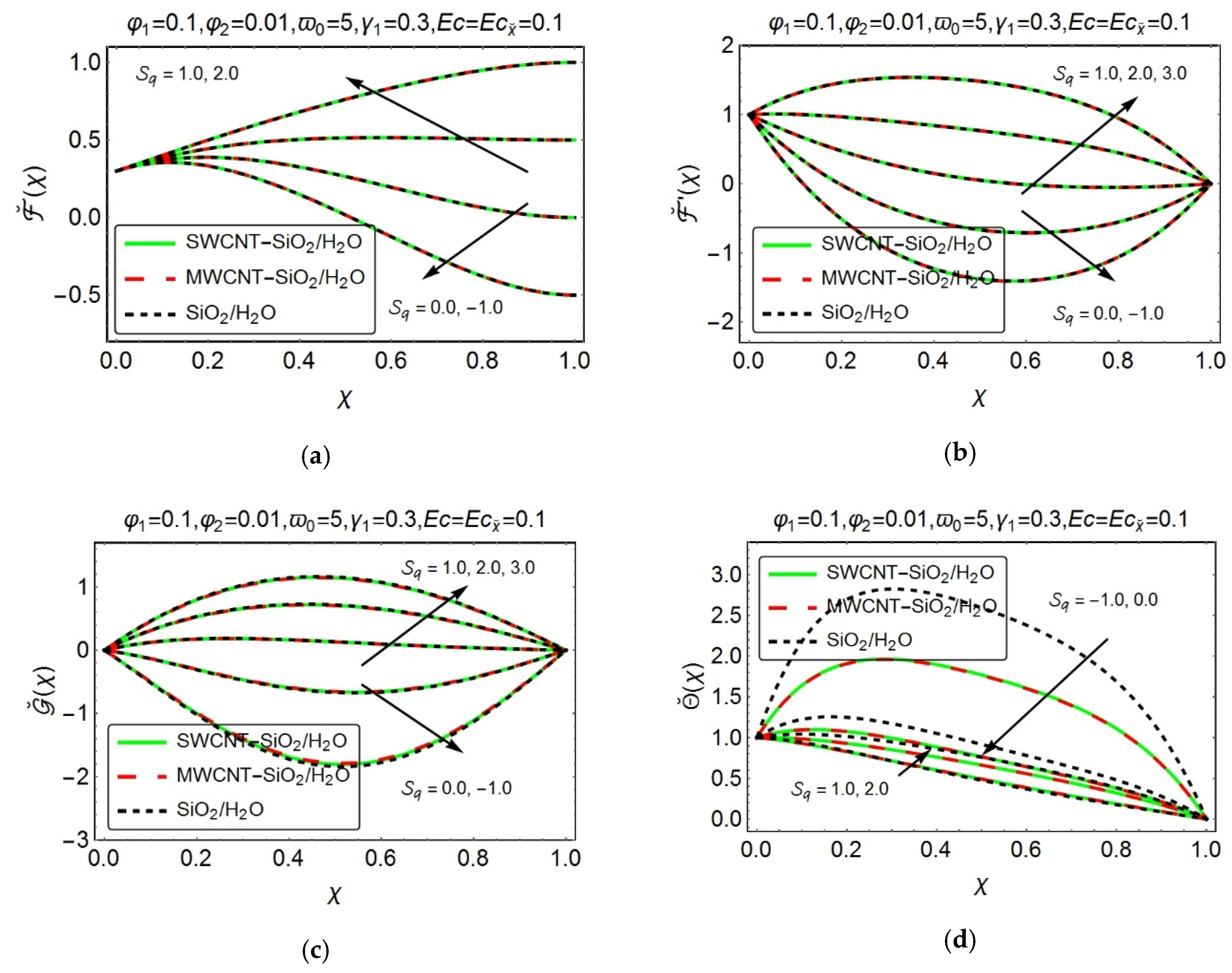
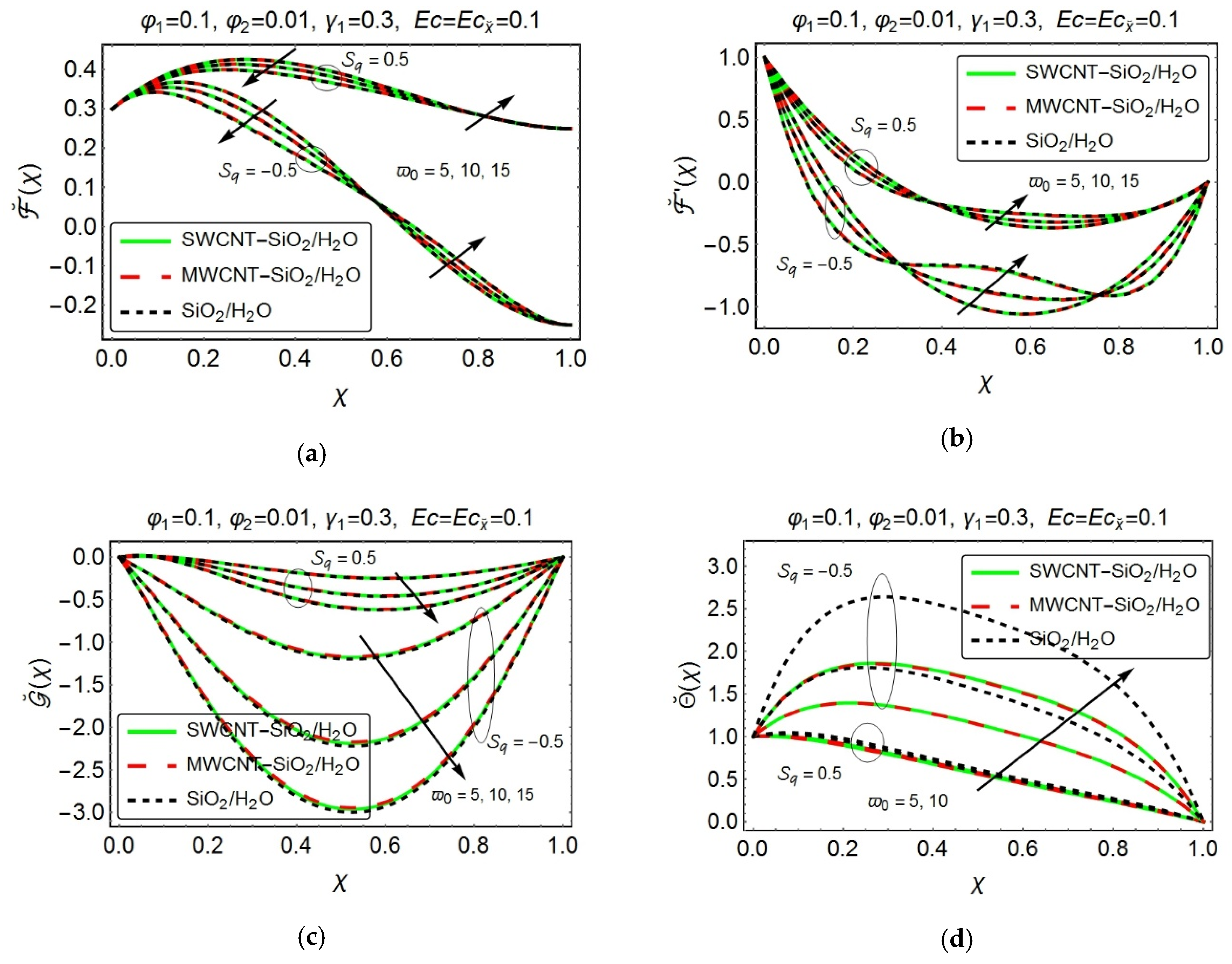
, unless indicated otherwise. The impact of a squeezed number S q on ˘ ( χ ) is specified in Figure 2a. The velocity component ˘ ( χ ) exhibit an increasing behavior, adjacent to the upper wall, as S q increases, which shows the significance of the squeezing behavior on the fluid flow. Figure 2b has been sketched, to check the influence of squeezing parameter S q on the axial velocity component ˘ ( χ ) . For S q < 0 , i.e., the case when the upper wall moves along the positive y ˘ direction, which in turn creates a vacant region nearby the upper wall. The adjacent fluid is then moved in the opposite direction, to fill this gap and as a result, a drop-in velocity has been perceived. Moreover, since the fluid has been continuously sucked from the stretching wall, which is placed at the lower end of the channel, therefore, a reversal flow has been observed at the central half of the channel. This phenomenon can also be observed for S q = 0 . The case, when S q > 0 , i.e., the upper wall moves in the negative y ˘ -direction, enforces a certain pressure on the adjacent fluid layers and hence, became a reason for an increment in the axial component of velocity. It is pertinent to note that the higher values of S q certainly, amortize the reversal behavior of the flow. From Figure 2c, it has been noticed that the transverse component of velocity G ˘ ( χ ) revealed the same behavior as depicted in Figure 2b. The increasing values of S q , gradually enhances the transverse component of velocity G ˘ ( χ ) and it seems to be dominant in the central half of the channel. Further, it has been noticed that the transverse velocity component possesses higher values for (MWCNT-SiO2/H2O) hybrid nanofluid. Figure 2d depicts the behavior of temperature distribution, under the influence of squeezing parameter S q . One can observe a clear decline in the temperature as the upper wall moves in the positive y ˘ direction ( S q < 0 ). On the other hand, when S q > 0 , i.e., the downward motion of the upper wall, enforces a squeezing force on the adjacent fluid layers. This, in turn, gives rise to the fluid velocity, which subsequently augments the viscous dissipative effects within the fluid and therefore, significantly augments the fluid temperature. Moreover, it has been detected that the temperature of (CNT-SiO2/H2O) hybrid nanofluid remains on the lower side as compared to (SiO2/H2O) nanofluid.
Figure 3 illustrates the velocity and temperature behaviors, under the action of suction parameter γ 1 . The rising values of γ 1 , significantly enhances the normal velocity component ˘ ( χ ) and this phenomenon seems to be more prominent in the lower half of the channel (see Figure 3a). Figure 3b reveals a decline in the axial component of velocity ˘ ( χ ) with the augmented γ 1 . Moreover, the larger suction values γ 1 supports the reversal flow behavior, which is more prevailing in the region adjacent to the upper wall. In the region close to the lower wall, the reverse flow is caused by the adverse pressure gradient, which is mainly due to the suction of the fluid from the lower permeable wall. Further, a sharp drop in axial velocity ˘ ( χ ) has been witnessed for the case when S q < 0 as compared to S q > 0 . S q < 0 corresponds to the case, when the upper wall moves in the positive y ˘ direction, which results a vicinity near the upper wall. The fluid is then moved inwards to fill this space and hence, a steep reversal behavior of the fluid has been observed near the upper wall of the channel. Almost alike behavior has been perceived for the transverse velocity component G ˘ ( χ ) , which has been presented in Figure 3c. Figure 3d elucidate the temperature variations with varying suction parameter γ 1 . An upsurge in temperature has been noticed with the increasing γ 1 . Also, the temperature distribution seems to be sufficiently high in the region nearby the lower wall as compared to the upper one. Suction, at the lower wall, could be the reason behind this behavior. It is also evident from this figure that the temperature boosts up in the middle portion of the channel. Further, when S q = 0.5 , the fluid temperature displays a significant increment as compared to the case when S q = 0.5 . It has also been noted that the (CNT-SiO2/H2O) hybrid nanofluid exhibit lower temperature profile, as compared to (SiO2/H2O) nanofluid.
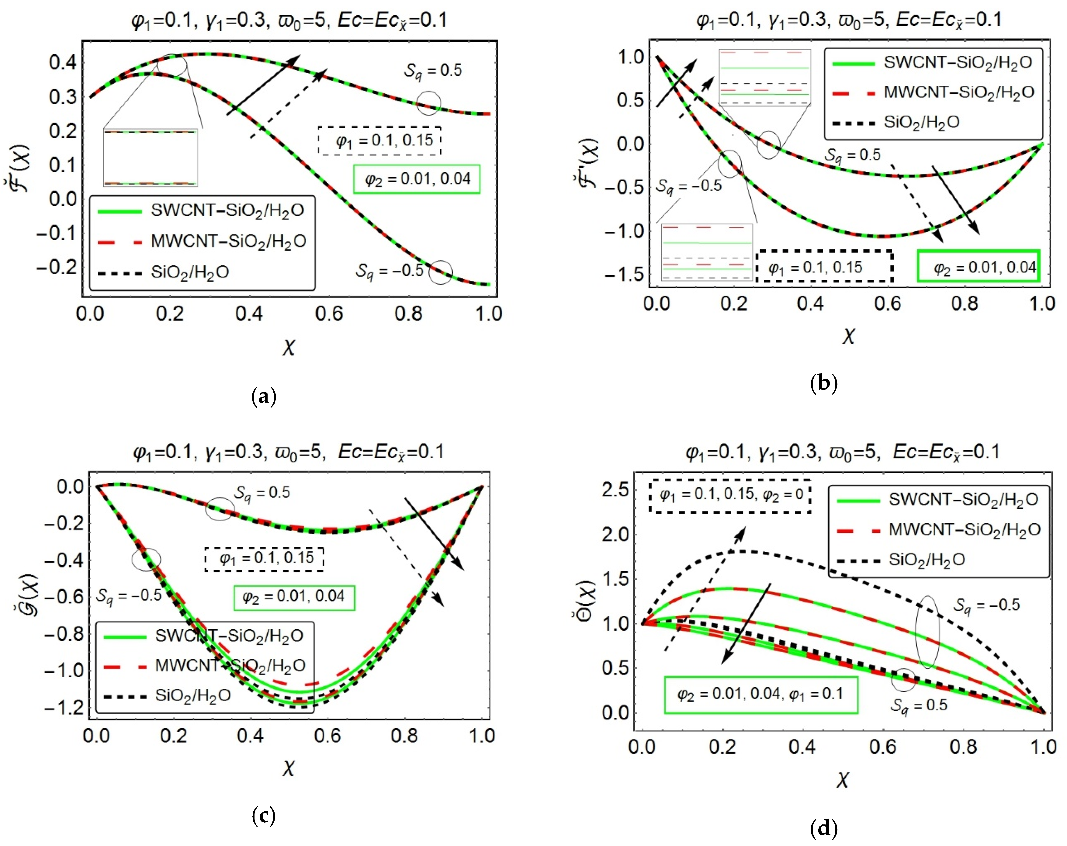
Figure 4 has been painted, to demonstrate the impact of nanoparticles volume fraction on the velocity and temperature profiles. From Figure 4a, one can witnesses an augmentation in the normal component of velocity ˘ ( χ ) with the growing values of nanoparticles volume fraction. The velocity component along x ˘ direction, ( ˘ ( χ ) ) , exhibit an increment in the vicinity, adjacent to the bottom permeable stretching wall of the channel, with increasing nanocomposites volume fraction, while, a reversed behavior has been detected in the middle and the upper half of the channel (see Figure 4b). Besides, the transverse velocity component G ˘ ( χ ) reveals a decreasing behavior with increasing nanoparticle volume fraction, which can be displayed in Figure 4c. It is evident from these pictures (Figure 4a–c) that the normal, axial, and transverse velocity components depict a higher velocity behavior, for the case when S q > 0 . Furthermore, the reversal flow phenomena have also been observed form Figure 4b,c. The inset pictures, from Figure 4a,b, reveals the fact that the (MWCNT-SiO2/H2O) hybrid nanofluid exhibit a slightly higher velocity as compared to (SWCNT-SiO2/H2O) hybrid nanofluid and (SiO2/H2O) nanofluid. The same behavior, for (MWCNT-SiO2/H2O) hybrid nanofluid, has been clearly noticed from Figure 4c. This could be due to the lower density values of the MWCNT , which significantly affects the velocity components, in the case of (MWCNT-SiO2/H2O) hybrid nanofluid. Figure 4d portrays the consequences of nanoparticles volume fraction on the temperature profile. Over here, the behavior is quite surprising one. A clear rise in temperature has been detected for (SiO2/H2O) nanofluid, with the increasing volume fraction; however, a drop in temperature has been perceived, for both (SWCNT-SiO2/H2O) and (MWCNT-SiO2/H2O) hybrid nanofluid. The reason perhaps be the increment in heat transfer, which appears to be quite significant, in a hybrid nanofluid. It has been further observed that the temperature profile depicts a remarkable advancement, for the case when S q = 0.5 . Interestingly, the (CNT-SiO2/H2O) hybrid nanofluid offers a slightly lesser temperature values as compared to (SiO2/H2O) nanofluid.
The next set of 
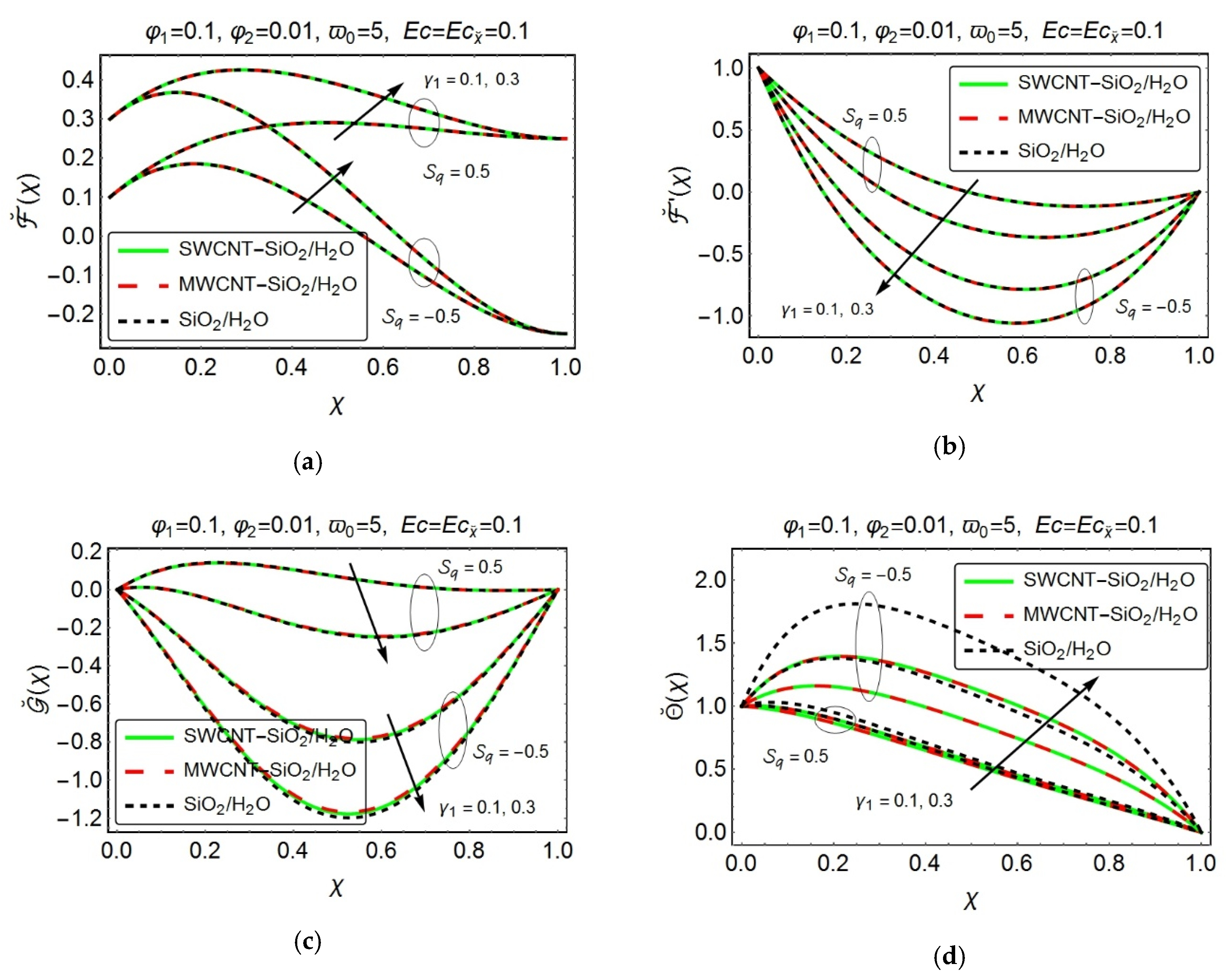
Figure 5a–5d provides a pictorial view of the impact of rotation parameter ϖ 0 on the velocity and temperature profiles. Figure 5a portrays an interesting behavior of the normal velocity component ˘ ( χ ) . With the rising ϖ 0 , the normal velocity component ˘ ( χ ) exhibit a continuous decline in the vicinage, nearby the lower wall and from the middle portion of the channel and onwards, an adverse trend has been perceived. It is also notable that the velocity possesses lower values, in the upper region of the channel as compared to the lower one. The deviations in the axial component of velocity ˘ ( χ ) , under the action of rotation parameter ϖ 0 , has been presented in Figure 5b. The environs, nearby lower wall, i.e., 0 χ 0.3 , exhibit a decelerated flow with the increasing ϖ 0 and the same behavior of velocity has been witnessed, in the region adjacent to the wall at the top i.e., 0.8 χ 1.0 . However, in the middle section of the channel, i.e., 0.3 χ 0.8 , the axial velocity ˘ ( χ ) displays an increasing behavior with the increasing ϖ 0 . The axial velocity ˘ ( χ ) for (SWCNT-SiO2/H2O) hybrid nanofluid remains on the higher side as compared to (MWCNT-SiO2/H2O) hybrid nanofluid, in the central half of the channel. Figure 5c shows the variation in the transverse velocity component G ˘ ( χ ) , with the growing values of ϖ 0 . A clear decrement in the transverse velocity component G ˘ ( χ ) has been noticed, with the increasing values of ϖ 0 . In addition, the normal, axial, and transverse components of velocity offer higher velocity values, for the case when S q = 0.5 . Moreover, the(SiO2/H2O) nanofluid provides a drop in the transverse module of velocity as compared to the (CNT-SiO2/H2O) hybrid nanofluid. Figure 5d graphically narrates the variation in temperature profile, with the growing values of ϖ 0 . The increasing values of ϖ 0 , certainly augments the temperature profile. The increasing rotation of channel and fluid, consequently, enhances the convection rate, which is the main reason behind this rising behavior. The case, when the upper wall moves in the negative y ˘ direction, i.e., S q = 0.5 delivers a low-temperature profile as compared to the case when S q = 0.5 . The fact behind this temperature difference is that when the upper wall moves in the opposite direction to the lower one ( S q = 0.5 ) , the vicinity, between the walls, confines a large amount of heated fluid, which consequently, give a certain rise to the temperature values of the fluid. However, when the upper wall moves in negative y ˘ direction ( S q = 0.5 ) , the amount of fluid certainly decreases between the parallel walls, and therefore a decrement in temperature values is quite evident in this case. Furthermore, the (SiO2/H2O) nanofluid bears higher temperature values as compared to (CNT-SiO2/H2O) hybrid nanofluid.
Figure 6 and 
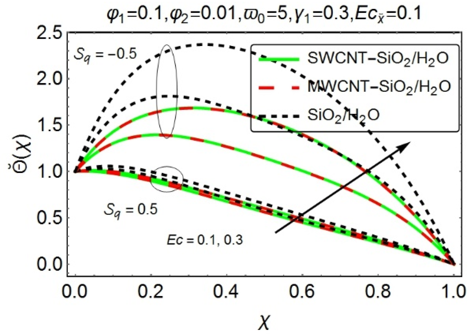
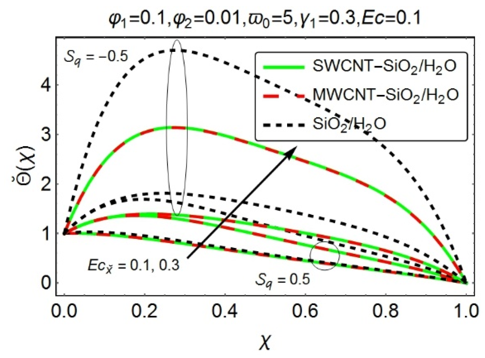
Figure 7 graphically elucidate the consequences of the Eckert number (both Ε c and Ε c x ˘ ) on the temperature profiles. Both the figures depict a considerable augmentation in the temperature profile, with the growing values of Eckert numbers. In fact, the rising values of Eckert number reveal the dominancy of viscous forces, inside the fluid which consequently enhances the kinetic energy of the fluid and hence, an upsurge in temperature has been perceived. Furthermore, the temperature values remain on the higher side, for the case when the wall at the top moves away from the lower one, i.e., S q = 0.5 . It is notable that the temperature for (CNT-SiO2/H2O) hybrid nanofluid seems to be least affected as compared to the temperature for (SiO2/H2O) nanofluid.
The next couple of Figure 8 and 
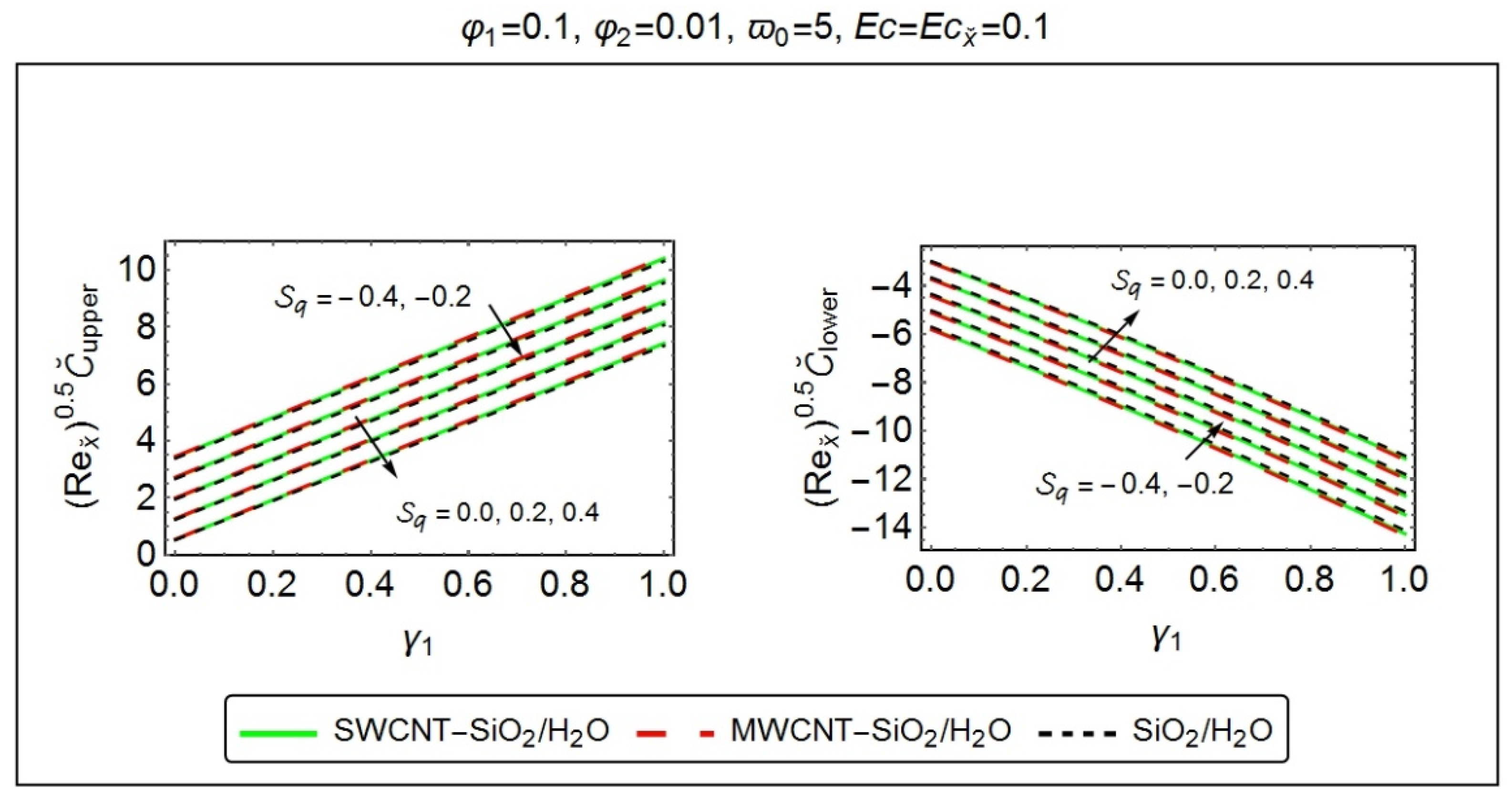
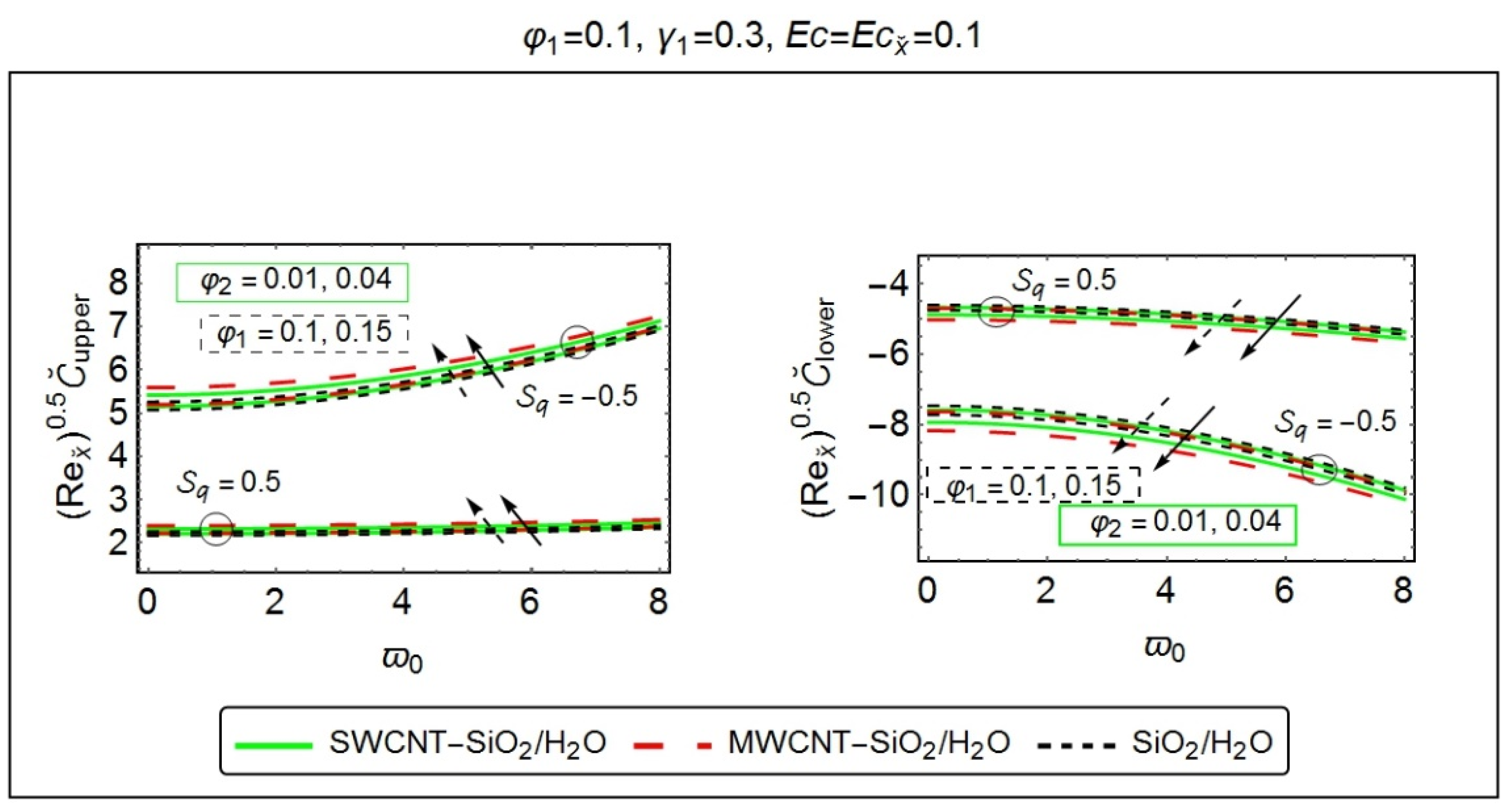
Figure 9, highlights the analysis of the skin friction coefficient, under the influence of various ingrained entities. Figure 8 has been sketched, to study the effect of squeezing parameter S q and suction parameter γ 1 on the skin friction coefficient. It has been discerned that when the upper wall moves in the negative y ˘ direction, i.e., S q > 0 , the skin friction coefficient display its dominancy at the wall placed at the lower extremity of the channel, which is possibly due to higher resistant forces, while, an opposite behavior has been recorded at the wall, located at the top of the channel. The instance, when the wall at the top moves in the upward direction, i.e., S q < 0 , an increment in the coefficient of skin friction has been perceived, at the upper end of the channel, with the increasing absolute values of S q . However, a reversed phenomenon has been identified at the other end of the channel. Besides, at the bottom of the channel, the skin friction coefficient for (CNT-SiO2/H2O) hybrid nanofluid depict a marginally low behavior then (SiO2/H2O) nanofluid, for the case when S q > 0 . As far as the suction parameter γ 1 is concerned, the increment in γ 1 clearly augments the coefficient of skin friction, at the top wall of the channel, while, at the other extremity of the channel, a declining behavior has been visible.
Figure 9 elaborates the consequences of nanoparticle volume fraction and rotation parameter ϖ 0 on the coefficient of skin friction. One can witness a decrement in the skin friction coefficient, with the increasing nanocomposite volume fraction at the bottom of the channel. Also, the coefficient of skin friction exhibits higher values, for the case, when the wall at the top moves toward the wall at the bottom, i.e., S q = 0.5 and these phenomena has been detected at the bottom end of the channel. On the upper extremity of the channel, the rising values of nanoparticles concentration certainly augment the skin friction coefficient. Moreover, the increment in the rotation parameter ϖ 0 causes a decline in the coefficient of skin friction at the lower edge of the channel, while the behavior is quite the opposite at the upper end of the channel. It is notable that, in both the scenarios, when S q = 0.5 and S q = 0.5 , the (MWCNT-SiO2/H2O) hybrid nanofluid possesses higher skin friction values, at the wall located at the upper side of the channel.
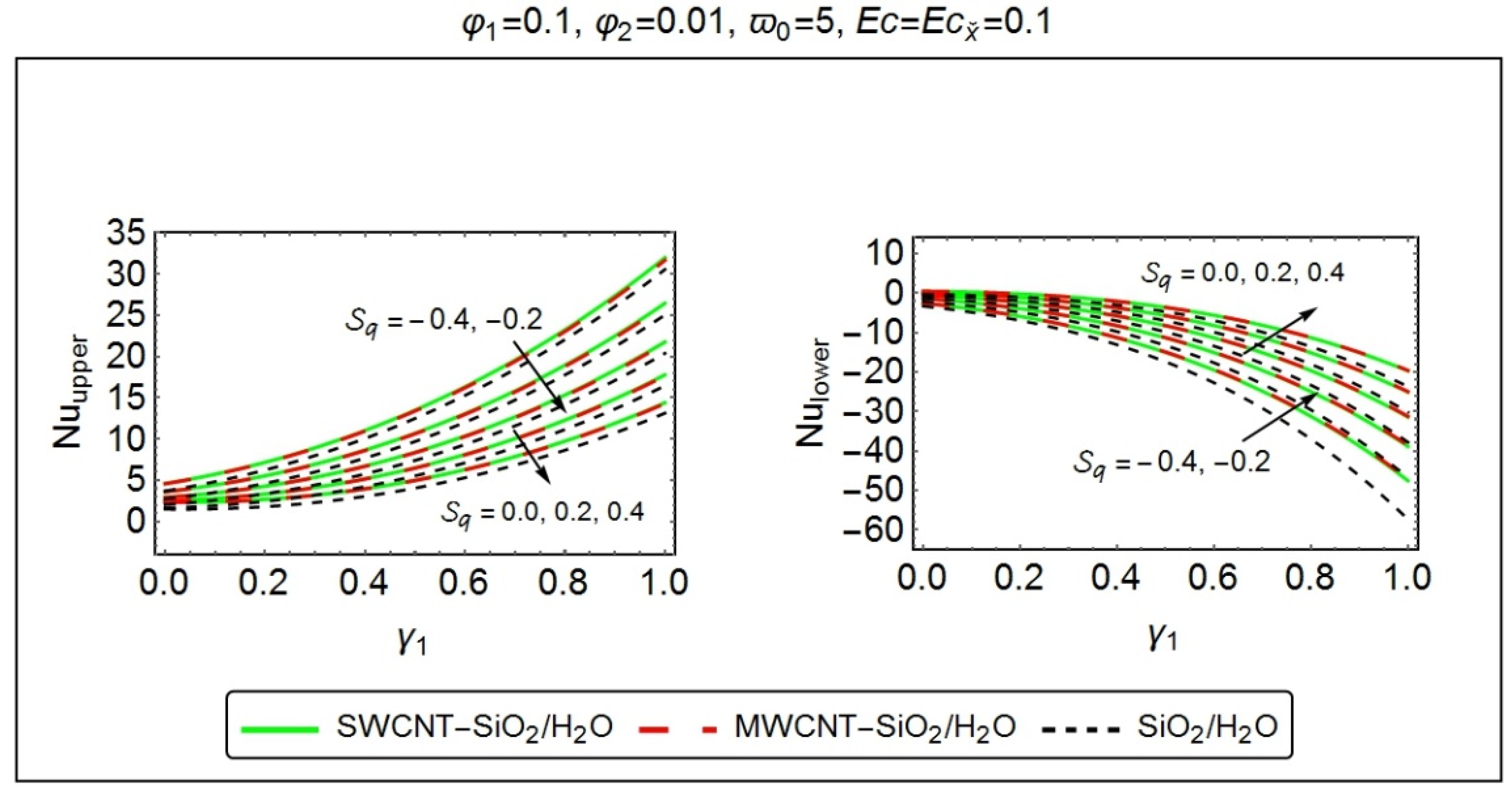
Figure 10, Figure 11 and Figure 12 has been designed, to investigate the consequences of various embedded parameters on the local rate of heat transfer, i.e., the Nusselt number. In this context, Figure 10 demonstrates the deviations in local Nusselt number, with the varying values of squeezing parameter S q and suction parameter γ 1 . The instance, when S q > 0 , the local rate of heat transfer reveals a declining behavior at the upper wall of the channel, which may be due to lesser temperature values at that extremity; however, a rising behavior has been achieved at the bottom wall of the channel. Also, when S q < 0 , the growing absolute values of S q causes a drop in the rate of heat transfer at the bottom end of the channel, while at the wall placed at the top of the channel, it behaves oppositely. Furthermore, at the bottom wall, the local Nusselt number appeared to deteriorate, with the increasing suction parameter γ 1 ; however, a reversed phenomenon has been recorded at the other end of the channel. It is further notable that the heat transfer rate for (CNT-SiO2/H2O) hybrid nanofluid displays its supremacy, at both walls of the channel.
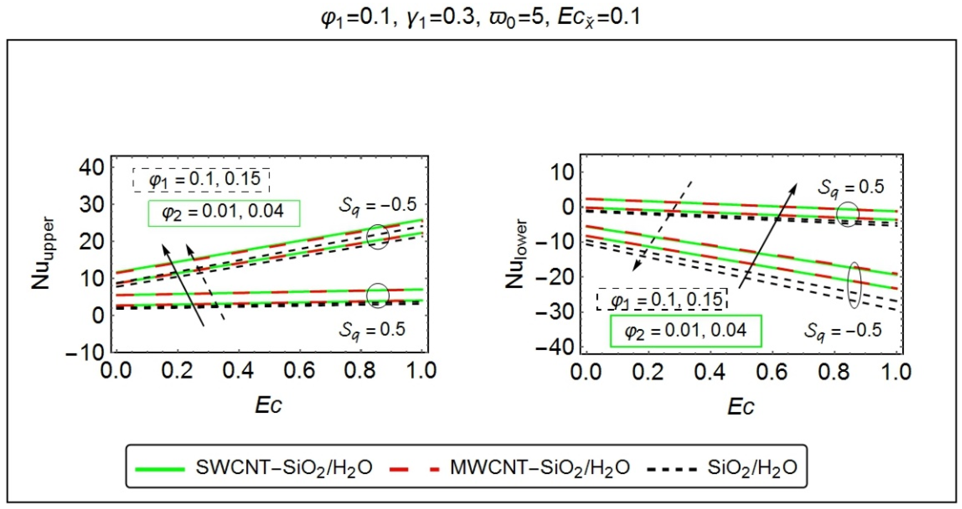
Figure 11 has been painted, to discuss the variations in the local rate of heat transfer, under the influence of nanoparticle volume fraction and the local Eckert number Ε c . The rise in nanoparticle volume fraction causes augmentation in the local heat transfer rate, and these phenomena are quite prominent at both walls of the channel. The fact behind this is that the inclusion of nanoparticles in the base fluid certainly enhances its thermal conductivity and consequently, the Nusselt number, which is the product of thermal conductivity and the temperature gradient, shows an increasing behavior. Moreover, a downfall in the rate of heat transfer has been perceived, at the lower end of the channel, with the rising values of the Eckert number. The reason behind, the increment of Eckert number is the dominancy of viscous diffusion within the energy equation, which, in turn, ascertains the decaying behavior of the local Nusselt number at the bottom wall of the channel. At the top wall, the increment in Ε c enhances the heat transfer rate. Also, at the bottom wall of the channel, the local heat transfer rate shows its proficiency in the case when the upper wall experiences a downward motion, i.e., S q = 0.5 and this behavior seems to be reversed at the upper end of the channel. Furthermore, the heat transfer rate in case of (CNT-SiO2/H2O) hybrid nanofluid significantly enhances, at both ends of the channel.
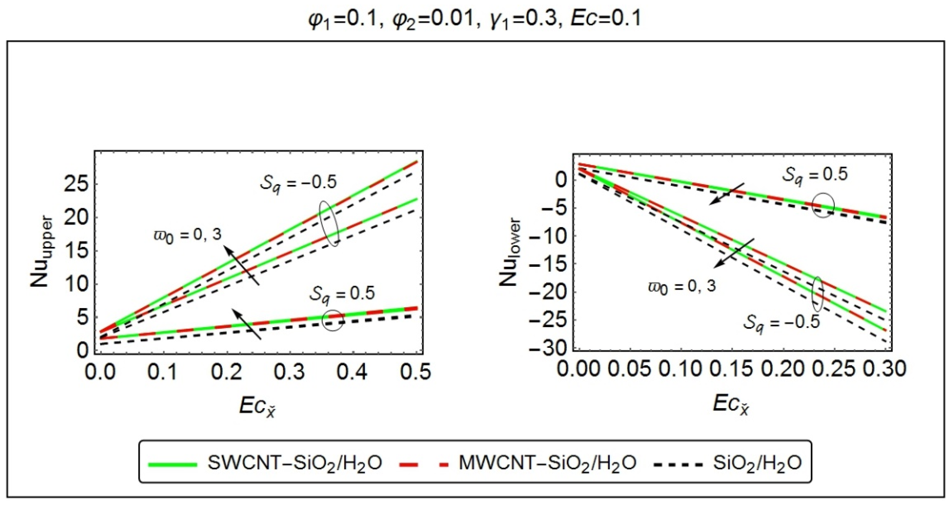
The consequences of the rotation parameter ϖ 0 and the modified Eckert number Ε c x ˘ on the local rate of heat transfer has been displayed, in Figure 12. At the lower wall of the channel, the local rate of heat transfer can be abated, with the increasing values of the rotation parameter ϖ 0 . Since the increment in rotation parameter ϖ 0 is due to the rise in Coriolis force as compared to viscous forces. Stronger Coriolis forces imply increment in rotation parameter ϖ 0 , which give rise to the heat transfer rate at the wall placed at the top of the channel. Moreover, the modified Eckert number Ε c x ˘ also, play a role in enhancing the heat transfer rate at the upper end of the channel; however, a reversed relationship has been observed at the bottom wall of the channel. Further, the case, when S q = 0.5 , the local heat transfer depicts higher values, nearby the upper extremity of the channel, while, it remains inferior at the other end of the channel. It is worth mentioning that the (CNT-SiO2/H2O) hybrid nanofluid displays higher heat transferring rate as compared to (SiO2/H2O) nanofluid at the both extremities of the channel.
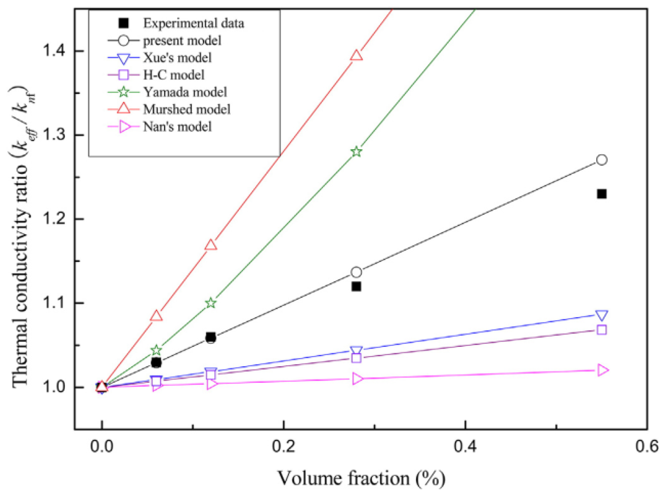
In the present study, a relatively new model, named ‘renovated Hamilton–Crosser model’ (proposed by Yang and Xu [1]), has been incorporated. This model includes the combined effects of CNTs diameter and aspect ratio along with the interfacial layer. For (MWCNT/H2O) nanofluid, the comparison of the results, for thermal conductivity ratio, obtained via renovated Hamilton–Crosser model has been made with the experimental data [45] as well as the previously existing models, like the Nan model, Murshed model, Yamada model, and Xue model. It has been found that the data, for carbon-nanotubes based nanofluid, acquired by the RHCM is constantly in accordance with the experimental data [45], as compared to other models. All these results can be clearly visualized from Figure 13.
Table 6, Table 7 and Table 8 have been fabricated with the results, procured by means of a modified Hermite wavelet method. Comparison with the previously published data of Butt and Ali [40] and Khan et al. [41] have also been taken into account. It has been found that the results are in good agreement with each other. MHWM involves the orthogonal polynomial basis functions that reduce the given problems to those of solving a system of algebraic equations, and thus, greatly simplifying the problem. Based on these facts, this method can be extended to the other physical problems of diversified nature.

6. Conclusions

The contribution of this article is to comprehensively discuss the consequences of various ingrained parameters, on the three-dimensional squeezing flow and heat transfer characteristics of (CNT-SiO2/H2O) hybrid nanofluid, which is confined inside a rotating channel. Among both walls, the lower one is permeable. The modified version of the Hermite wavelet method has been endorsed, to tackle the nonlinear physical model, associated with the present flow problem. The major upshots are enlisted below:
  • The instance, when S q > 0 , the normal, axial, and transverse velocity components expedite with the increasing values of squeezing parameter S q .
  • The increment in the suction parameter γ 1 accelerate the flow in a normal direction; however, in axial and transverse direction, the reversal flow has been perceived.
  • The normal velocity component ˘ ( χ ) , certainly enhances with the increasing nanoparticle volume fraction; however, the axial and transverse velocity behaves differently.
  • Both the normal and axial velocity component exhibit dual behavior, with the increasing rotation parameter ϖ 0 , while, a transverse velocity component G ˘ ( χ ) experiences declining behavior.
  • The augmentation in temperature has been recorded, with the increasing values of various embedded parameters like suction parameter γ 1 , the rotation parameter ϖ 0 and Eckert number (both Ε c and Ε c x ˘ ). Further, the (CNT-SiO2/H2O)hybrid nanofluid offers a slightly lesser temperature value as compared to (SiO2/H2O)nanofluid.
  • The dispersion of CNTs with different volume fractions, in (SiO2/H2O) nanofluid contributes to reducing the temperature of the fluid.
  • The temperature profile depicts a remarkable advancement for S q < 0 .
  • The increment in S q give rise to the skin friction coefficient at the bottom wall of the channel, while, a reversed phenomenon has been perceived at the other wall of the channel.
  • The inclusion of nanoparticles enhances the skin friction coefficient at the wall located at the upper side of the channel, while a decrement has been noticed at the bottom wall.
  • The skin friction coefficient drops at the lower end of the channel with the increasing suction parameter γ 1 and rotation parameter ϖ 0 . The (CNT-SiO2/H2O) hybrid nanofluid slightly lessens the coefficient of skin friction at the lower extremity of the channel.
  • The Nusselt number seems to be dropping, with the rising values of the suction parameter γ 1 and rotation parameter ϖ 0 , at the lower end of the channel.
  • The nanoparticle volume concentration enhances the local rate of heat transfer, at the upper walls of the channel. It is noteworthy that the (CNT-SiO2/H2O) hybrid nanofluid display higher heat transferring rate as compared to (SiO2/H2O) nanofluid, at both ends of the channel.
  • The error analysis endorsed that the modified version of the Hermite wavelet method is suitable for handling the nonlinear physical models and can be extended to the other physical problems of diversified nature.

Author Contributions

Conceptualization, U.K. and I.K.; Investigation, F.S., S.N., Z.B., and E.M.S.; Methodology, N.A.; Supervision, S.T.M.-D.

Funding

This research is funded from the Project number (RSP-2019/33), King Saud University, Riyadh, Saudi Arabia.

Acknowledgments

Researchers Supporting Project number (RSP-2019/33), King Saud University, Riyadh, Saudi Arabia.

Conflicts of Interest

The authors declare no conflict of interest.

Nomenclature

c Rate of Stretching of the surface at y ˘ = 0 , ( s 1 )
n 1 Empirical shape factor
g Empirical parameter
e ( 𝕦 ) Eccentricity
Length of the CNT, ( μ m )
Radius of the CNT, ( n m )
d Diameter of the CNT, ( n m )
𝕥 Thickness of the interfacial layer, ( n m )
K h n f Thermal conductivity of the hybrid nanofluid, ( W m 1 K 1 )
K b f Thermal conductivity of the nanofluid, ( W m 1 K 1 )
K p 1 Thermal conductivity of the S i O 2 nanoparticles, ( W m 1 K 1 )
K p 2 Thermal conductivity of the CNT s nanoparticles, ( W m 1 K 1 )
K f Thermal conductivity, ( W m 1 K 1 )
p ˘ Dimensional pressure, ( N m 2 )
V 0 Rate of penetration, ( m s 1 )
C p Specific heat at constant pressure, ( J k g 1 K 1 )
T ˘ Temperature, ( K )
u ˘ , v ˘ , w ˘ Velocity component along x ˘ , y ˘ and z ˘ directions, respectively, ( m s 1 )
Dimensionless Parameters
P r Prandtl number
E c Eckert number
N u Nusselt number
S q Squeezing number
ϖ 0 Rotation parameter
γ 1 Suction parameter
Ε c x ˘ Modified Eckert number
R e x ˘ Local Reynolds number
Greek Symbols
ψ ˘ Sphericity
α ˘ Dilation parameter
β ˘ Translation parameter
Ω ˘ Rotation velocity, ( m s 1 )
κ Characteristic parameter, ( s 1 )
χ Similarity variable
τ w Shear stress, ( N m 2 )
φ 1 Solid volume fraction of S i O 2 nanocomposites
φ 2 Solid volume fraction of CNT s nanocomposites
υ f Kinematic viscosity of water, ( m 2 s 1 )
ρ ˘ f Density of water, ( k g m 3 )
ρ ˘ p 1 Density of S i O 2 nanoparticles, ( k g m 3 )
ρ ˘ p 2 Density of CNT s nanoparticles, ( k g m 3 )
μ f Dynamic viscosity of the host fluid (water), ( N . s m 2 )
( ρ ˘ C p ) f Specific heat capacity of the water, ( J K 1 )
( ρ ˘ C p ) p 1 Specific heat capacity of S i O 2 nanoparticles, ( J K 1 )
( ρ ˘ C p ) p 2 Specific heat capacity of CNT s nanoparticles, ( J K 1 )
Subscripts
h n f Hybrid Nanofluid
b f Mono nanofluid
f Host fluid (Water)
r Interfacial layer around the CNTs
p e x CNT/layer composites in the radial direction
p e z CNT/layer composites in the axial direction
Abbreviations
H 2 O Water
SiO 2 Silicon dioxide
CNT Carbon nanotubes
HAM Homotopy Analysis Method
RKF Runge Kutta Fehlberg Method
MHWM Modified Hermite Wavelet Method
SWCNT Single-walled carbon nanotubes
MWCNT Multi-walled carbon nanotubes
RHCM Renovated Hamilton–Crosser Model

References

  1. Choi, S.U.S. Enhancing thermal conductivity of fluids with nanoparticles. In Developments and Applications of Non-Newtonian Flows; Singer, D.A., Wang, H.P., Eds.; ASME: New York, NY, USA, 1995; Volume 231, pp. 99–106. [Google Scholar]
  2. Choi, S.U.S.; Zhang, Z.G.; Yu, W.; Lockwood, F.E.; Grulke, E.A. Anomalous thermal conductivity enhancement in nanotube suspensions. Appl. Phys. Lett. 2001, 79, 2252–2254. [Google Scholar] [CrossRef]
  3. Maxwell, J.C. Electricity Amd Magnetism, 3rd ed.; Clarendon: Oxford, UK, 1904. [Google Scholar]
  4. Hamilton, R.L.; Crosser, O.K. Thermal conductivity of heterogeneous two-component systems. Ind. Eng. Chem. Fundam. 1962, 1, 187–191. [Google Scholar] [CrossRef]
  5. Buongiorno, J. Convective transport in nanofluids. J. Heat Transf. 2006, 128, 240–250. [Google Scholar] [CrossRef]
  6. Keblinski, P.; Phillpot, S.R.; Choi, S.U.S.; Eastman, J.A. Mechanisms of heat flow in suspensions of nano-sized particles (nanofluids). Int J Heat Mass Transf. 2001, 45, 855–863. [Google Scholar] [CrossRef]
  7. Keblinski, P.; Eastman, J.A.; Cahill, D.G. Nanofluids for thermal transport. Mater. Today 2005, 8, 36–44. [Google Scholar] [CrossRef]
  8. Timofeeva, E.V.; Routbort, J.L.; Singh, D. Particle shape effects on thermophysical properties of alumina nanofluids. J. Appl. Phys. 2009, 106, 014304. [Google Scholar] [CrossRef]
  9. Machrafi, H.; Lebon, G. The role of several heat transfer mechanisms on the enhancement of thermal conductivity in nanofluids. Contin. Mech. Therm. 2016, 28, 1461–1475. [Google Scholar] [CrossRef]
  10. Timofeeva, E.V.; Gavrilov, A.N.; McCloskey, J.M.; Tolmachev, Y.V.; Sprunt, S.; Lopatina, L.M.; Selinger, J.V. Thermal conductivity and particle agglomeration in alumina nanofluids: Experiment and theory. Phys. Rev. E 2007, 76, 061203. [Google Scholar] [CrossRef] [Green Version]
  11. Machrafi, H.; Lebon, G.; Iorio, C.S. Effect of volume-fraction dependent agglomeration of nanoparticles on the thermal conductivity of nanocomposites: Applications to epoxy resins, filled by SiO2, AlN and MgO nanoparticles. Compos. Sci. Technol. 2016, 130, 78–87. [Google Scholar] [CrossRef] [Green Version]
  12. Iijima, S. Helical microtubules of graphitic carbon. Nature 1991, 354, 56–58. [Google Scholar] [CrossRef]
  13. Saito, R.; Dresselhaus, G.; Dresselhaus, M.S. Physical Properties of Carbon Nanotubes; Imperial College Press: Singapore, 2001. [Google Scholar]
  14. Endo, M.; Hayashi, T.; Ahm Kim, Y.; Terrones, M.; Dresselhaus, M.S. Applications of carbon nanotubes in the twenty-first century. Philos. Trans. R. Soc. A Math. Phys. Eng. Sci. 2004, 362, 2223–2238. [Google Scholar] [CrossRef] [PubMed]
  15. Xue, Q.Z. Model for thermal conductivity of carbon nanotube-based composites. Phys. B Condens. Matter. 2005, 368, 302–307. [Google Scholar] [CrossRef]
  16. Murshed, S.M.S.; Nieto de Castro, C.A.; Lourenço, M.J.V.; Lopes, M.L.M.; Santos, F.J.V. A review of boiling and convective heat transfer with nanofluids. Renew. Sustain. Energy Rev. 2011, 15, 2342–2354. [Google Scholar] [CrossRef]
  17. Yang, L.; Xu, X. A renovated Hamilton–Crosser model for the effective thermal conductivity of CNTs nanofluids. Int. Commun. Heat Mass Transf. 2017, 81, 42–50. [Google Scholar] [CrossRef]
  18. Yu, W.; Choi, S.U.S. The role of interfacial layers in the enhanced thermal conductivity of nanofluids: A renovated Maxwell model. J. Nanoparticle Res. 2003, 5, 167–171. [Google Scholar] [CrossRef]
  19. Yu, W.; Choi, S.U.S. The role of interfacial layers in the enhanced thermal conductivity of nanofluids: A renovated Hamilton?Crosser model. J. Nanoparticle Res. 2004, 6, 355–361. [Google Scholar] [CrossRef]
  20. Jiang, H.; Xu, Q.; Huang, C.; Shi, L. The role of interfacial nanolayer in the enhanced thermal conductivity of carbon nanotube-based nanofluids. Appl. Phys. A 2015, 118, 197–205. [Google Scholar] [CrossRef]
  21. Sarkar, J.; Ghosh, P.; Adil, A. A review on hybrid nanofluids: Recent research, development and applications. Renew. Sustain. Energy Rev. 2015, 43, 164–177. [Google Scholar] [CrossRef]
  22. Ranga Babu, J.A.; Kumar, K.K.; Srinivasa Rao, S. State-of-art review on hybrid nanofluids. Renew. Sustain. Energy Rev. 2017, 77, 551–565. [Google Scholar] [CrossRef]
  23. Niihara, K. New design concept of structural ceramics. J. Ceram. Soc. Jpn. 1991, 99, 974–982. [Google Scholar] [CrossRef] [Green Version]
  24. Jana, S.; Salehi-Khojin, A.; Zhong, W.H. Enhancement of fluid thermal conductivity by the addition of single and hybrid nano-additives. Thermochim. Acta 2007, 462, 45–55. [Google Scholar] [CrossRef]
  25. Suresh, S.; Venkitaraj, K.P.; Selvakumar, P.; Chandrasekar, M. Synthesis of Al2O3-Cu/water hybrid nanofluids using two step method and its thermo physical properties. Colloids Surf. A Physicochem. Eng. Asp. 2011, 388, 41–48. [Google Scholar] [CrossRef]
  26. Suresh, S.; Venkitaraj, K.P.; Selvakumar, P.; Chandrasekar, M. Effect of Al2O3–Cu/water hybrid nanofluid in heat transfer. Exp. Therm. Fluid Sci. 2012, 38, 54–60. [Google Scholar] [CrossRef]
  27. Abbasi, S.M.; Rashidi, A.; Nemati, A.; Arzani, K. The effect of functionalisation method on the stability and the thermal conductivity of nanofluid hybrids of carbon nanotubes/gamma alumina. Ceram. Int. 2013, 39, 3885–3891. [Google Scholar] [CrossRef]
  28. Sundar, L.S.; Singh, M.K.; Sousa, A.C.M. Enhanced heat transfer and friction factor of MWCNT-Fe3O4/water hybrid nanofluids. Int. Commun. Heat Mass Transf. 2014, 52, 73–83. [Google Scholar] [CrossRef]
  29. Hemmat, M.; Seyfolah, E.; Yan, S.W. Study on thermal conductivity of water-based nanofluids with hybrid suspensions of CNTs/Al2O3 nanoparticles. J. Therm. Anal. Calorim. 2016, 124, 455–460. [Google Scholar] [CrossRef]
  30. Devi, S.P.A.; Devi, S.S.U. Numerical investigation of hydromagnetic hybrid Cu-Al2O3/water nanofluid flow over a permeable stretching sheet with suction. Int. J. Nonlinear Sci. Numer. Simul. 2016, 17, 249–257. [Google Scholar] [CrossRef]
  31. Momin, G.G. Experimental investigation of mixed convection with water-Al2O3 & hybrid nanofluid in inclined tube for laminar flow. Int. J. Sci. Technol. Res. 2013, 2, 195–202. [Google Scholar]
  32. Olatundun, A.T.; Makinde, O.D. Analysis of Blasius flow of hybrid nanofluids over a convectively heated surface. Defect Diffus. Forum. 2017, 377, 29–41. [Google Scholar] [CrossRef]
  33. Das, S.; Jana, R.N.; Makinde, O.D. MHD flow of Cu-Al2O3/water hybrid nanofluid in porous channel: Analysis of entropy generation. Defect Diffus. Forum 2017, 377, 42–61. [Google Scholar] [CrossRef]
  34. Hayat, T.; Nadeem, S. Heat transfer enhancement with Ag–CuO/water hybrid nanofluid. Results Phys. 2017, 7, 2317–2324. [Google Scholar] [CrossRef]
  35. Stefan, M.J. Versuch uber die scheinbare adhasion, sitzungsber. Abt. II Osterr. Akad. Wiss. MathNaturwiss. kl. 1874, 69, 713–721. [Google Scholar]
  36. Langlois, W.E. Isothermal squeeze films. Q. Appl. Math. 1962, 20, 131–150. [Google Scholar] [CrossRef] [Green Version]
  37. Salbu, E.O.J. Compressible squeeze films and squeeze bearings. J. Basic Eng. 1965, 86, 355–364. [Google Scholar] [CrossRef]
  38. Thorpe, J.F. Further investigation of squeezing flow between parallel plates. Development in Theoretical and Applied Mathematics, 3rd ed.; Pergamon Press: Oxford, UK, 1967; pp. 635–648. [Google Scholar] [CrossRef]
  39. Munawar, S.; Mehmood, A.; Ali, A. Three-dimensional squeezing flow in a rotating channel of lower stretching porous wall. Comput. Math. Appl. 2012, 64, 1575–1586. [Google Scholar] [CrossRef] [Green Version]
  40. Butt, A.S.; Ali, A. Analysis of entropy generation effects in unsteady squeezing flow in a rotating channel with lower stretching permeable wall. J. Taiwan Inst. Chem. Eng. 2015, 48, 8–17. [Google Scholar] [CrossRef]
  41. Khan, U.; Ahmed, N.; Mohyud-Din, S.T. Numerical investigation for three dimensional squeezing flow of nanofluid in a rotating channel with lower stretching wall suspended by carbon nanotubes. Appl. Therm. Eng. 2017, 113, 1107–1117. [Google Scholar] [CrossRef]
  42. Ghadikolaei, S.S.; Hosseinzadeh, K.; Ganji, D.D. Investigation on three dimensional squeezing flow of mixture base fluid (ethylene glycol-water) suspended by hybrid nanoparticle (Fe3O4-Ag) dependent on shape factor. J. Mol. Liq. 2018, 262, 376–388. [Google Scholar] [CrossRef]
  43. Kefayati, G.H.R.; Hosseinizadeh, S.F.; Gorji, M.; Sajjadi, H. Lattice Boltzmann simulation of natural convection in tall enclosures using water/SiO2 nanofluid. Int. Commun. Heat Mass Transf. 2011, 38, 798–805. [Google Scholar] [CrossRef]
  44. Saeed, U.; Rehman, M.U. Hermite wavelet method for fractional delay differential equations. J. Differ. Equations 2014, 2014, 359093. [Google Scholar] [CrossRef] [Green Version]
  45. Estellé, P.; Halelfadl, S.; Maré, T. Lignin as dispersant for water-based carbon nanotubes nanofluids: Impact on viscosity and thermal conductivity. Int. Commun. Heat Mass 2014, 57, 8–12. [Google Scholar] [CrossRef]
Figure 1. Physical model of the present flow situation.
Processes 07 00937 g001
Figure 2. Impact of some specific values of squeezing parameter ( S q ) on (a) normal velocity component ˘ ( χ ) , (b) axial velocity component ˘ ( χ ) , (c) transverse velocity component G ˘ ( χ ) , and (d) temperature profile Θ ˘ ( χ ) .
Processes 07 00937 g002
Figure 3. Impact of some specific values of a suction parameter ( γ 1 ) on (a) normal velocity component ˘ ( χ ) , (b) axial velocity component ˘ ( χ ) , (c) transverse velocity component G ˘ ( χ ) , and (d) temperature profile Θ ˘ ( χ ) .
Processes 07 00937 g003
Figure 4. Impact of some specific values of nanoparticle volume fractions ( φ 1 and φ 2 ) on (a) normal velocity component ˘ ( χ ) , (b) axial velocity component ˘ ( χ ) , (c) transverse velocity component G ˘ ( χ ) , and (d) temperature profile Θ ˘ ( χ ) .
Processes 07 00937 g004
Figure 5. Impact of some specific values of the rotation parameter ( ϖ 0 ) on (a) normal velocity component ˘ ( χ ) , (b) axial velocity component ˘ ( χ ) , (c) transverse velocity component G ˘ ( χ ) , and (d) temperature profile Θ ˘ ( χ ) .
Processes 07 00937 g005
Figure 6. Impact of some specific values of Eckert number ( Ε c ) on temperature profile Θ ˘ ( χ ) .
Processes 07 00937 g006
Figure 7. Impact of some specific values of modified Eckert number ( Ε c x ˘ ) on temperature profile Θ ˘ ( χ ) .
Processes 07 00937 g007
Figure 8. Coefficient of skin friction drag for some specific values of squeezing parameter ( S q ) and suction parameter ( γ 1 ) .
Processes 07 00937 g008
Figure 9. Coefficient of skin friction drag for some specific values of nanoparticle volume fractions ( φ 1 and φ 2 ) and rotation parameter ( ϖ 0 ) .
Processes 07 00937 g009
Figure 10. Local rate of heat flux for some specific values of squeezing parameter ( S q ) and suction parameter ( γ 1 ) .
Processes 07 00937 g010
Figure 11. Local rate of heat flux for some specific values of nanoparticle volume fractions ( φ 1 and φ 2 ) and Eckert number ( Ec ) .
Processes 07 00937 g011
Figure 12. Local rate of heat flux for some specific values of the rotation parameter ( ϖ 0 ) and modified Eckert number ( Ε c x ˘ ) .
Processes 07 00937 g012
Figure 13. The comparison of various models, for thermal conductivity of ( MWCNT / H 2 O ) nanofluid, with the Estellé et al.’s experimental data [45].
Processes 07 00937 g013
Table 1. Thermo-physical properties of water ( H 2 O ) and the nanomaterials ( SiO 2 and CNTs ) [41,43].
H 2 O ( f ) S i O 2 S W C N T M W C N T
ρ ˘ ( k g   m 3 ) 997.1 3970 2600 1600
C p ( J   k g 1 K 1 ) 4179 765 425 796
K ( W m 1 K 1 ) 0.613 36 6600 3000
Pr 6.2
Table 2. Numerical values of the coefficients j i , i = 1 , 2 , 3 .
i j i
j 1 2 3
0 0.2999999999741 5.620504062165 × 10 16 0.999999999914
1 0.999999999914 0.477130259959 0.218093790981
2 2.443812381789 5.00567720057 5.31413343454
3 1.878893272838 8.71431047325 10.2894660191
4 0.603175632348 5.88541111849 10.7888398791
5 0.044920973296 2.26049113481 6.19867248046
6 0.0731737680737 0.56084354885 1.60325897686
Table 3. Comparison of the procured data for ˘ ( χ ) for single-walled carbon nanotubes (SWCNT-SiO2/H2O) hybrid nanofluid with ( φ 1 = 0.1 ) .
χ R K F M H W M A b s o l u t e   E r r o r
0.00.30.32.593641968 × 10−11
0.10.37740390470.377380972.293046022 × 10−5
0.20.4163354550.416332632.827271419 × 10−6
0.30.42602817220.426063783.561081736 × 10−5
0.40.41452221760.4145576033.538503405 × 10−5
0.50.38876179320.38875720714.586071578 × 10−6
0.60.35484439350.35480397774.041579712 × 10−5
0.70.31836226290.31832854473.371814744 × 10−5
0.80.28478903810.2847944615.422909814 × 10−6
0.90.25987280460.25989456022.175554662 × 10−5
1.00.250.254.161085365 × 10−11
Table 4. Comparison of the procured data for G ˘ ( χ ) for (SWCNT-SiO2/H2O) hybrid nanofluid with ( φ 1 = 0.1 ) .
χ R K F M H W M A b s o l u t e   E r r o r
0.005.620504062 × 10−165.620504062 × 10⁻¹⁶
0.10.0058020942640.0058040674191.973155666 × 10−6
0.2−0.04382408744−0.043815746868.340585765 × 10−6
0.3−0.1146903718−0.11467317881.719292621 × 10−5
0.4−0.1821413741−0.18215668841.531427835 × 10−5
0.5−0.2294710274−0.22952638845.536096274 × 10−5
0.6−0.2465663136−0.24661478094.846736954 × 10−5
0.7−0.2289378517−0.22893130126.55048326 × 10−6
0.8−0.1772168988−0.17717066844.62303143 × 10−5
0.9−0.0971404644−0.09712504461.541980722 × 10−5
1.009.99850272 × 10−119.99850272 × 10⁻¹¹
Table 5. Comparison of the procured data for Θ ˘ ( χ ) for (SWCNT-SiO2/H2O) hybrid nanofluid with ( φ 1 = 0.1 ) .
χ R K F M H W M A b s o l u t e   E r r o r
0.010.99999999998.646217076 × 10−11
0.10.97795208960.97793901021.307943899 × 10−5
0.20.89790590750.89798797178.206423352 × 10−5
0.30.79153142120.79147610595.531524871 × 10−5
0.40.67628024250.67621514856.509400443 × 10−5
0.50.5609551340.56105189029.67562121 × 10−5
0.60.44908794120.44926637110.0001784299275
0.70.34078445270.34081572873.127594595 × 10−5
0.80.23357424720.23342369910.0001505481632
0.90.12256944280.12251577225.367065929 × 10−5
1.00−2.631228568 × 10−142.631228568 × 10⁻¹⁴
Table 6. Comparison of procured results for ˘ ( 0 ) with the previously published data ( φ 1 = φ 2 = 0 ) .
γ 1 S q ϖ 0 ˘ ( 0 ) H A M [40] ˘ ( 0 ) R K F [40,41] ˘ ( 0 ) M H W M
0.32.00.50.0257240.0257240.025724
0.8 −3.369658−3.369658−3.369658
1.2 −6.311701−6.311701−6.311701
0.5−1.01 −10.214133−10.214133−10.214133
0.0 −7.419696−7.419696−7.419696
1.0 −4.445146−4.445146−4.445146
2.0 −1.297045−1.297045−1.297045
1.0−1.291472−1.291472−1.291472
5.0−1.110254−1.110254−1.110254
10.0−0.522086−0.522086−0.522086
Table 7. Comparison of procured results for G ˘ ( 0 ) with the previously published data ( φ 1 = φ 2 = 0 ) .
γ 1 S q ϖ 0 G ˘ ( 0 ) H A M [40] G ˘ ( 0 ) R K F [40,41] G ˘ ( 0 ) M H W M
0.32.00.50.3726820.3726820.372682
0.8 0.1722820.1722820.172282
1.2 −0.040879−0.040879−0.040879
0.5−1.01 −0.707731−0.707731−0.707731
0.0 −0.237555−0.237555−0.237555
1.0 0.0757820.0757820.075782
2.0 0.3003130.3003130.300313
1.00.6004740.6004740.600474
5.02.9795372.9795372.979537
10.05.8443965.8443965.844396
Table 8. Comparison of procured results for Θ ˘ ( 0 ) with the previously published data ( φ 1 = φ 2 = 0 ) .
γ 1 S q ϖ 0 Ε c Ε c x ˘ P r Θ ˘ ( 0 ) H A M [40] Θ ˘ ( 0 ) R K F [40] Θ ˘ ( 0 ) M H W M
0.52.00.50.20.21.00.9062440.9062440.906244
0.7 0.9251220.9251220.925122
1.2 0.2638670.2638670.263867
0.5−1.00.50.20.21.03.1389263.1389263.138926
0.0 0.8333200.8333200.833320
1.0 0.5005810.5005810.500581
0.52.01.00.20.21.00.8997820.8997820.899782
5.0 0.6970040.6970040.697004
10.0 0.1059670.1059670.105967
0.52.00.50.00.21.01.1104331.1104331.110433
0.5 0.5999620.5999620.599962
1.0 0.0894920.0894920.089492
0.52.00.50.20.01.01.0182411.0182411.018241
0.5 0.7382490.7382490.738249
1.0 0.4582560.4582560.458256
0.52.00.50.20.22.00.8058920.8058920.805892
3.00.6992220.6992220.699222
5.00.4686540.4686540.468654

