Article

CFD Study of Gas Holdup and Frictional Pressure Drop of Vertical Riser Inside IC Reactor

1
Key Laboratory for Green Chemical Technology of Ministry of Education, Tianjin University, Tianjin 300072, China
2
R&D Center for Petrochemical Technology, Tianjin University, Tianjin 300072, China
3
Collaborative Innovation Center of Chemical Science and Engineering, Tianjin 300072, China
*
Author to whom correspondence should be addressed.
Processes 2019, 7(12), 936; https://doi.org/10.3390/pr7120936
Submission received: 6 November 2019 / Revised: 2 December 2019 / Accepted: 4 December 2019 / Published: 9 December 2019
(This article belongs to the Special Issue Processes for Bioenergy and Resources Recovery from Biowaste)

Abstract

:
The internal circulation system in Internal Circulation (IC) reactor plays an important role in increasing volumetric loading rate and promoting the mixing between sludge and wastewater. In order to design the internal circulation system, the flow behaviors of gas-liquid inside vertical riser should be studied in detail. In the present study, the Multiple Flow Regimes model is adopted to capture the phase interface for different flow conditions. The flow patterns, internal circulation flow rate, gas holdup, and frictional pressure drop of vertical riser are investigated. The results show that the bubble flow inside a vertical riser is in a stable flow condition. There exists a maximum value for internal circulation flow rate with the increasing superficial gas velocity. The parameters of Martinelli models for gas holdup and frictional pressure drop are improved based on Computational Fluid Dynamics (CFD) results. The deviations between the calculated gas holdup and frictional pressure drop by improved model and experimental value are reduced to 14% and 13.2%, respectively. The improved gas holdup and frictional pressure drop model can be used for the optimal design of internal circulation system.

1. Introduction

The internal circulation system in Internal Circulation (IC) reactor can increase the volumetric loading rate and biogas production obviously [1]. It provides the high superficial liquid velocity to make the granular sludge fluidized and promotes the mixing between sludge and sewage. The vertical riser supplies the driving force for the internal circulation, which is closely related to its structure and flow patterns. The detailed study of flow behaviors inside vertical riser could provide the guidelines for the design of IC reactor.
Since 1990s, the design of IC reactor relies on the empirical correlations for gas holdup and superficial liquid velocity. Pereboom [2] proposed a mathematical equation for the calculation of the superficial liquid velocity of vertical riser. Based on this equation, the internal circulation flow rate can be obtained. Hu [3] improved Pereboom’s equation considering the actual operational condition and a deepened mechanical analysis. However, these equations were derived based on pilot tests or mathematical inference. In addition, some parameters are set as constant. Therefore, the empirical correlations may not be suitable for all conditions and result in large deviations for actual operation.
The calculation of frictional pressure drop is important for the force balance analysis in the design of IC anaerobic reactor. Many researchers have focused on the calculation of frictional pressure drop, and different calculation formulas were developed based on experimental results [4,5,6]. Up to now, there is no universal formula for the frictional pressure drop calculation because of the lack of a deep understanding of the flow behaviors inside the vertical riser.
Computational Fluid Dynamics (CFD) method is a powerful tool to predict the behavior of gas–liquid two-phase flow and is found in a number of engineering applications, for example, porous materials [7,8], petroleum industry [9,10], aerospace industry [11,12,13], and IC systems [14,15]. Hanafizadeh et al. [16] used the Eulerian–Eulerian model to study the effect of bubble diameter and tapering angle on performance of airlift pump. The results showed that the liquid mass flow rate increased with the decrease of bubble diameter. Abdulkadir et al. [17] used the Volume Of Fluid (VOF) method to study the slug flow of vertical riser. It was found that simulated results for average gas holdup showed good consistency with experiments. With the decreasing bubble size and increasing tapering angle, the performance of the pump was improved. In addition, Hanafizadeh et al. [18] compared the VOF and Eulerian–Eulerian model and found that VOF model is more suitable for bubble flow and slug flow, while Eulerian–Eulerian model is more suitable for annular flow. Even though, the gas holdup and frictional pressure drop can still not be predicted accurately.
The commonly used methods for two-phase flow are Eulerian–Eulerian and VOF. However, both of them have shortcomings. Eulerian averaging [19,20] of transport equations results in additional interactions between the phases that require models for closure, like drag force, lift force, interphase heat transfer, etc. The closure relationships for these terms are the biggest source of uncertainty for the multi-fluid model [21]. The VOF model mainly focuses on capturing the interface between two immiscible fluids [22] but ignores the interaction between the two phases. It must be noted that the cost in terms of computational effort is very high for capturing the phase interface. The multiple flow regimes (MFR) model was developed to simulate multi-scale multiphase flow combining the advantages for Eulerian–Eulerian model and VOF model [23,24,25,26,27]. The model has been verified in typical two-phase flow, such as dam break process, stratified flow process, and liquid drop oscillation process [28].
The present work mainly focused on the detailed hydrodynamic behaviors of vertical riser under different operational conditions. The MFR model was used to investigate the effects of the superficial gas velocity and immersion ratio on the flow patterns and internal circulation flow rate. The gas holdup and frictional pressure drop of gas–liquid two-phase flow were predicted and analyzed. Based on the CFD simulation results, the key parameter models for the design of internal circulation system of IC reactor, such as gas holdup and frictional pressure drop, were assessed and improved.

2. Mathematical Model and Method

2.1. Conventional Model for Internal Circulation System

As shown in Figure 1, the driving force for the internal circulation system is provided by the second reaction chamber and the vertical riser. The energy balance equation can be simplified as below:
ρ l g H = Δ P F + Δ P g + Δ P a
where ρ l is the density of liquid, H is the height from the bottom of the second reaction chamber to the outlet of wastewater, Δ P F is the frictional pressure drop, Δ P g is the gravitational pressure drop, Δ P a is the accelerational pressure drop.
The two-phase gravitational and accelerational pressure drop are determined as follows [29]:
Δ P g = ρ m g L
  ρ m = α ρ g + ( 1 α ) ρ l  
  Δ P a = ( G l 2 ( 1 α ) ρ l + G g 2 α ρ g G l 2 ρ l )  
where ρ m is the mean density of liquid and gas, L is the length of the vertical riser, α is the gas holdup, ρ g is the density of gas, ρ l is the density of liquid, G l is the mass flux of liquid, G g is the mass flux of gas.
Martinelli models [30] are widely used to predict the gas holdup α of gas–liquid two-phase flow.
X t t = ( W l W g ) 0.9 · ( ρ g ρ l ) 0.5 · ( μ l μ g ) 0.1
where   X t t is the Martinelli parameter, W l is the mass flow rate of liquid, and W g is the mass flow rate of gas (kg/s).
Martinelli gave the relationship between the parameter X t t defined by the above formulas and the gas holdup α in the gas–liquid two-phase flow as a graph, while Chisholm [31] expressed it as the following formula:
α = 1 ( 1 1 X t t 2 + 21 X t t + 1 ) 0.5
The frictional pressure drop of gas–liquid two-phase flow in the pipeline can be expressed as follows:
Δ P F = ϕ 2 · ( Δ P F ) l
where ϕ 2 is the two-phase friction multiplier, ( Δ P F ) l the frictional pressure drop when there is only liquid in the pipe.
( Δ P F ) l = 2 f L · G l 2 d · ρ l
where f can be calculated according to the McAdams relationship:
f = 0.184 ( R e ) l 0.2
ϕ 2 can be calculated as follows:
ϕ 2 = 1 + 21 X t t + ( 1 X t t ) 2
The internal circulation flow rate can be calculated as flow:
ρ l g H = ρ m g L + ϕ 2 · ( Δ P F ) l + ( G l 2 ( 1 α ) ρ l + G g 2 α ρ g G l 2 ρ l )
According to Equation (11), if the gas flow rate in the riser is known, the internal circulation flow rate can be calculated by iteration. However, for a lack of better prediction method for gas holdup and frictional pressure drop, the internal circulation flow rate and the design of IC anaerobic reactor are still difficult to achieve. In the present study, the gas holdup and frictional pressure drop can be obtained by CFD method.

2.2. Multiple Flow Regimes (MFR) Model

The gas–liquid two-phase flow in the vertical riser was simulated by MFR model. This model could describe the dispersed and segregated phase flows within a single framework. The topological structure and physical characteristics of phase interface could be redefined. The calculation process and equations in this section for two-phase flow can be summarized as below [23]:
  • For the interaction of multiphase flow, a primary phase and a secondary phase are defined. For example, water is designated as the first phase and air as the second phase.
  • According to the definition of interphase action, three topological structures are defined: the main phase flow pattern, air as the dispersed phase (bubble); the interface flow pattern, water and air are not the dispersed phase; the secondary phase flow pattern, water as the dispersed phase (droplet).
  • The mesh with large interface is detected, the general topological structure in each mesh is determined, and the weight functions of each topological structure are calculated, which are M f r , M i r , and M s r , respectively.
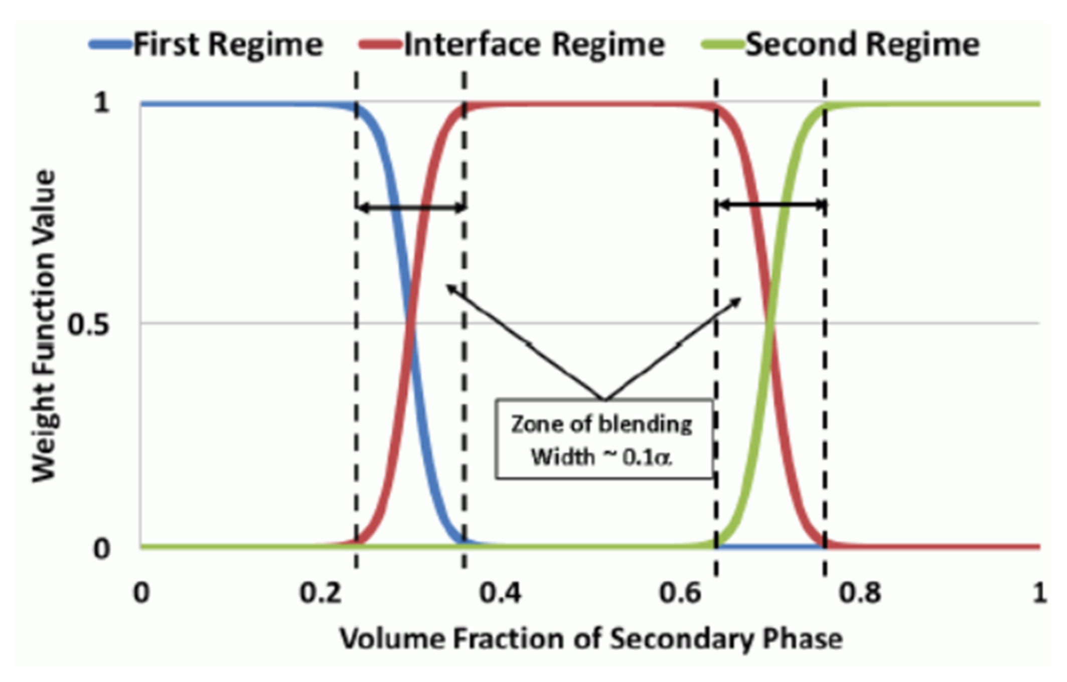
  • Calculation of the interphase forces of each sub-topology in all meshes: F f r , F i r , F s r . The subscripts fr, ir, and sr represent first regime, interface regime, and second regime, respectively. The relationships between weight function of three regimes and volume fraction of second phase can be found in Figure 2.
  • The total interaction force of each sub-topology is calculated by weight function and interaction force:
    F t o t a l = M f r F f r + M i r F i r + M s r F s r
In the MFR model, the large scale interface detection model (LIM) [28] is used to detect the grid in a large interface. A detailed description can be found in STARCCM+ User Guide 12.02 [23].
For a pair of primary and secondary phases, the flow topology is defined based on the volume fraction of the secondary phase ( ε s )as:
0.0 < ε s < ε f r : First   Regime ε f r < ε s < ε s r :   Interface   Regime ε s r < ε s < 1.0 : Sec ond   Regime
When the first regime terminus ( ε f r ) is the value of ε s for which the first regime transits to the interface regime. The default value is taken as 0.3 [23]. When the second regime onset ( ε s r ) is the value of ε s for which the interface regime transits to the second regime. The default value is taken as 0.3.

2.3. Geometry Model and Mesh Generation

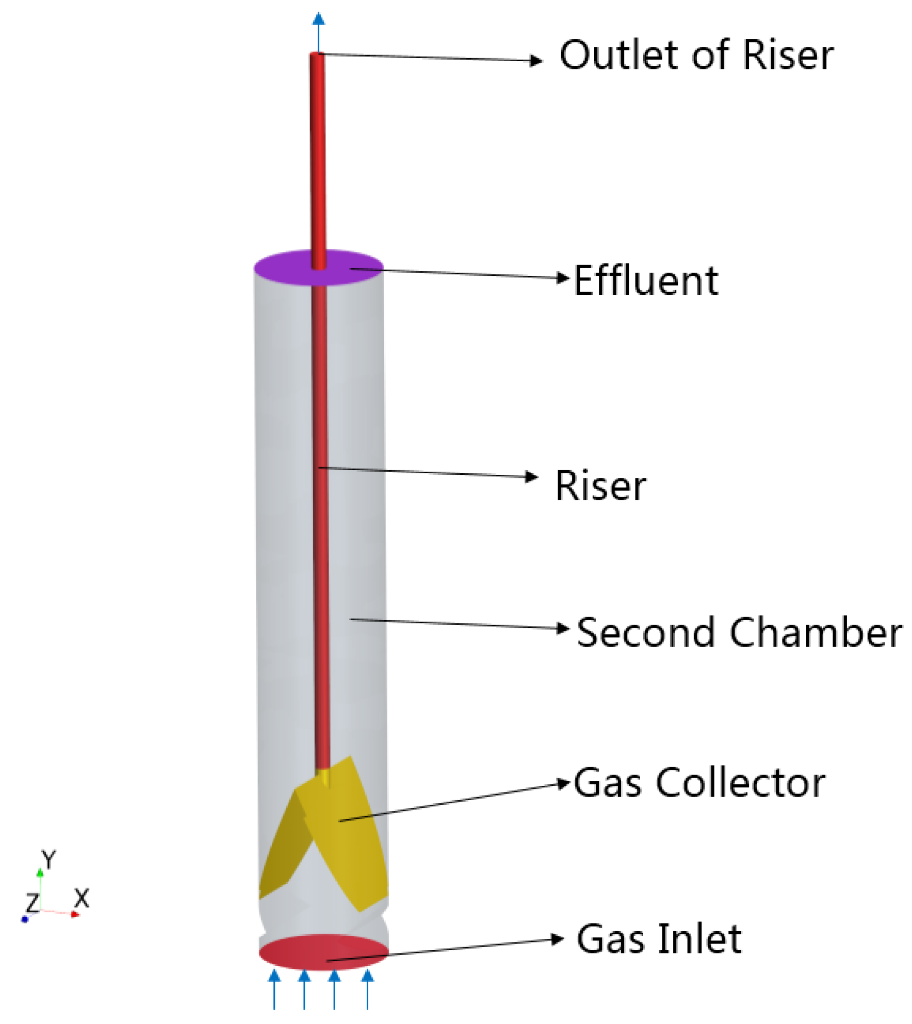
The geometric model of internal circulation system is shown in Figure 3, which includes a vertical riser, gas collector, and the second reaction chamber. The bottom surface is set as the velocity inlet of gas. The inlet diameter is 1.75 m and the diameter of vertical riser is 0.2 m. The inlet gas velocity is between 0.04486~0.314 m/s, i.e., 0.108~0.755 kg/s. The top outlet is the pressure outlet (101,325 Pa), and the liquid level of second reaction chamber is the pressure inlet (101,325 Pa). All walls are set as no-slip condition (fluid velocity is zero). Under different inlet velocities, the apparent gas velocity(vg) in the vertical riser is between 3.115~21.81 m/s, and the immersion ratio is between 0.5~0.9.
The geometric model of internal circulation system was discretized by using polyhedral mesh. The mesh size was determined through the mesh independence test. As shown in Figure 4, the liquid flow rate varied with the base mesh size. It can be seen that when the base mesh size is less than 0.24 m, the liquid flow rate has no obvious change. Therefore, the base mesh size of 0.24 m was adopted for all cases in this work. The detailed parameters used for the surface and volume mesh generation can be found in Eppinger’s work [32]. The mesh topology of computational domain was shown in Figure 5.

3. Results and Discussion

3.1. Flow Patterns and Internal Circulation Flow Rate

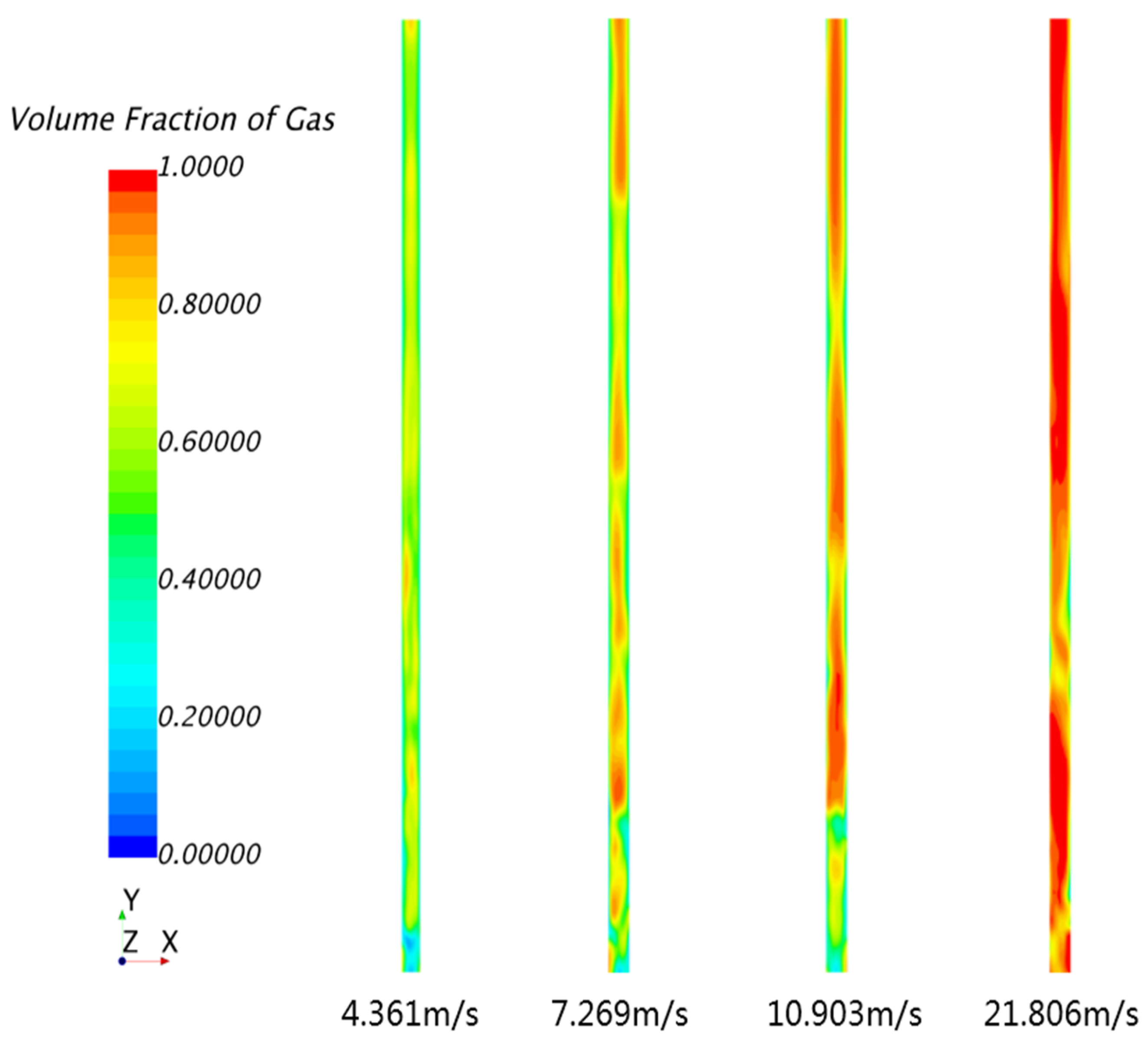
Figure 6 shows the distributions of gas holdup of the riser at different superficial gas velocities. It can be seen that as the superficial gas velocity increases, the flow patterns gradually change from a bubble flow, via a slug flow to a churn flow. As shown in Figure 7, under the same superficial gas velocity of riser (vg), the driving force for the liquid rise increases as the immersion ratio increase. The flow pattern changes from a slug flow to a bubble flow. The flow patterns are determined by the relative magnitudes of superficial gas velocity and liquid velocity. For higher superficial gas velocity, the gas bubbles tend to be aggregated and larger local gas holdups can be found.
Figure 8 shows the change of liquid flow rate with time for bubble flow (A), slug flow (B), and churn flow (C). Compared to the slug flow and the churn flow, the bubble flow has a smaller fluctuation range and shorter fluctuation period. For the bubble flow, the interaction between bubbles is smaller and its distribution is more uniform. Therefore, the liquid flow rate is more stable under the bubble flow. As can be seen in Figure 8B, when t = 15.23 s, a large gas slug appears at the exit. The outlet of the vertical riser is occupied by gas, resulting in a decrease of liquid flow rate. When the gas slug passes through the riser outlet, the liquid flow rate changed with time into a relatively stable stage, in which the riser outlet mainly presents a bubble flow. When t = 16.4 s, the exit of the riser presents the slug flow pattern again. As shown in Figure 8C, due to the blocky gases, the liquid flow rate is extremely unstable. In conclusion, the flow pattern in the riser should be controlled within the bubble flow as far as possible for the design of internal circulation system.
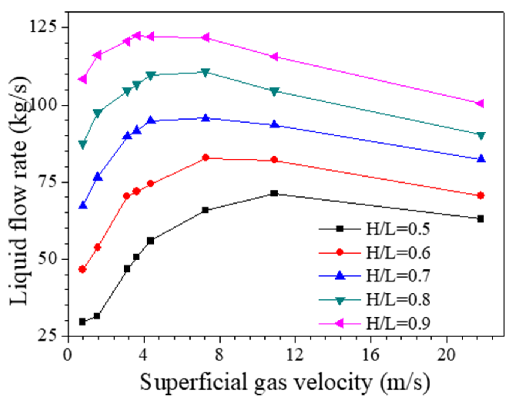
Figure 9 shows the liquid flow rate under different superficial gas velocities and immersion ratios. It can be seen that with the increase of immersion ratio, the internal circulation flow rate increases gradually. The larger immersion ratios supply a larger driving force of internal circulation. With the increase of the superficial gas velocity, the internal circulation flow rate does not always increase. When the superficial gas velocity is less than 4.36 m/s, the increase of internal circulation flow rate is obvious. For the bubble flow (smaller superficial gas velocity), the interaction between gas and liquid is stronger than that of slug flow. However, when the superficial gas velocity is greater than 7.27 m/s, the internal circulation flow rate decreases with the increase of the superficial gas velocity. Under this circumstance, the interaction between gas and liquid is weak, and the gas slug or churn is easy to get out of the riser. The maximum flow rate of the internal circulation appears when the immersion ratio is 0.9 and the superficial gas velocity is between 3.16 m/s~4.36 m/s. The high superficial gas velocity will lead to the center position of the riser being occupied by gas, resulting in a decrease of liquid flow rate. When the immersion ratio is 0.8 and the superficial gas velocity is 7.27 m/s, the liquid flow rate is 110.71 kg/s. When the immersion ratio is 0.9 and the superficial gas velocity is 0.778 m/s, the liquid flow rate is 108.35 kg/s. There is little difference in liquid flow rate between these two conditions, but the difference in superficial gas velocity is about 9.5 times. This result shows that it is not an effective solution to increase the internal circulation flow rate by increasing the superficial gas velocity (reducing the diameter of the riser). The measures to be taken is increasing the height from the bottom of the second reaction chamber to the outlet of the wastewater as much as possible, and then adjust the superficial gas velocity between 3.16 m/s and 4.36 m/s to achieve a higher internal circulation flow rate.
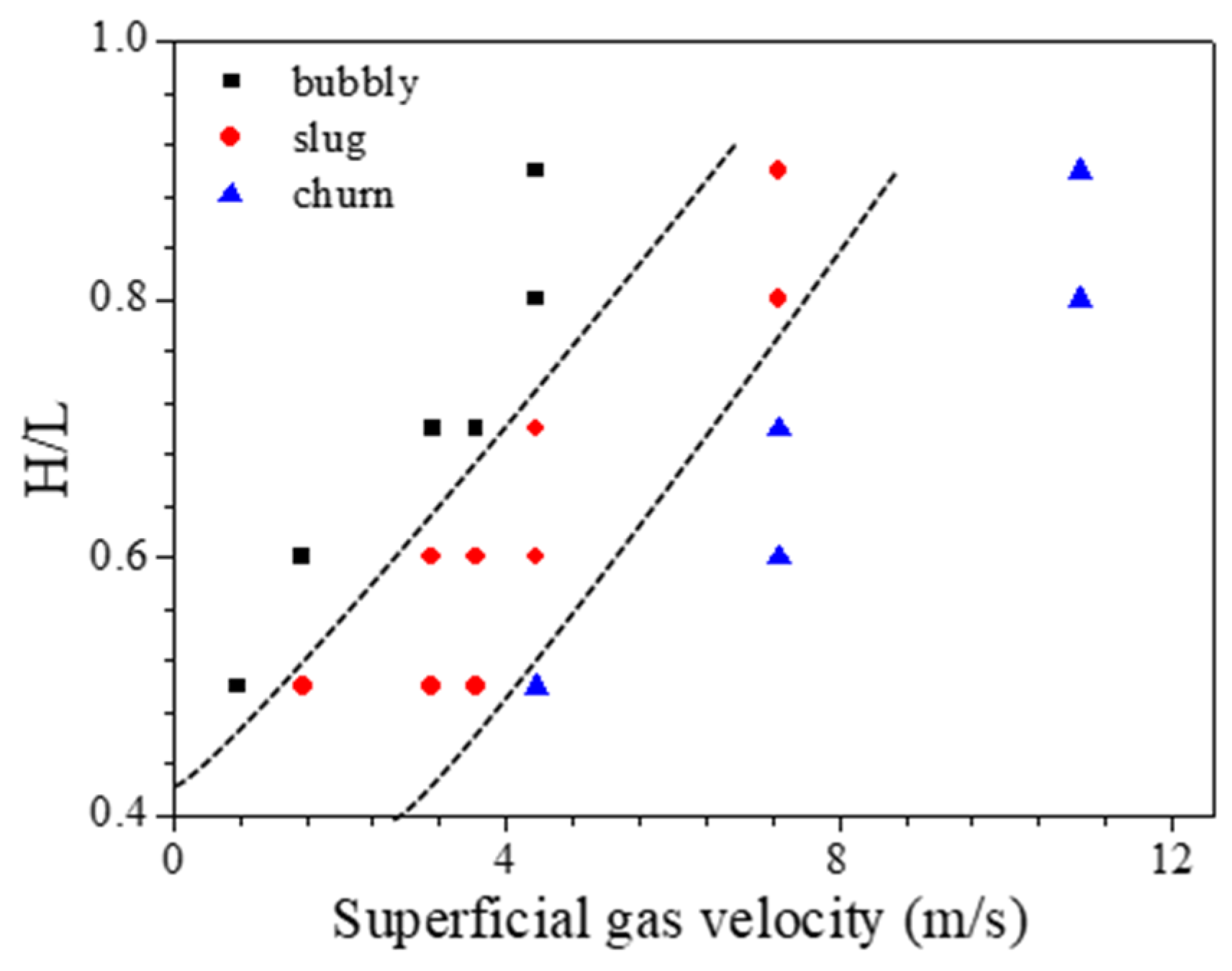
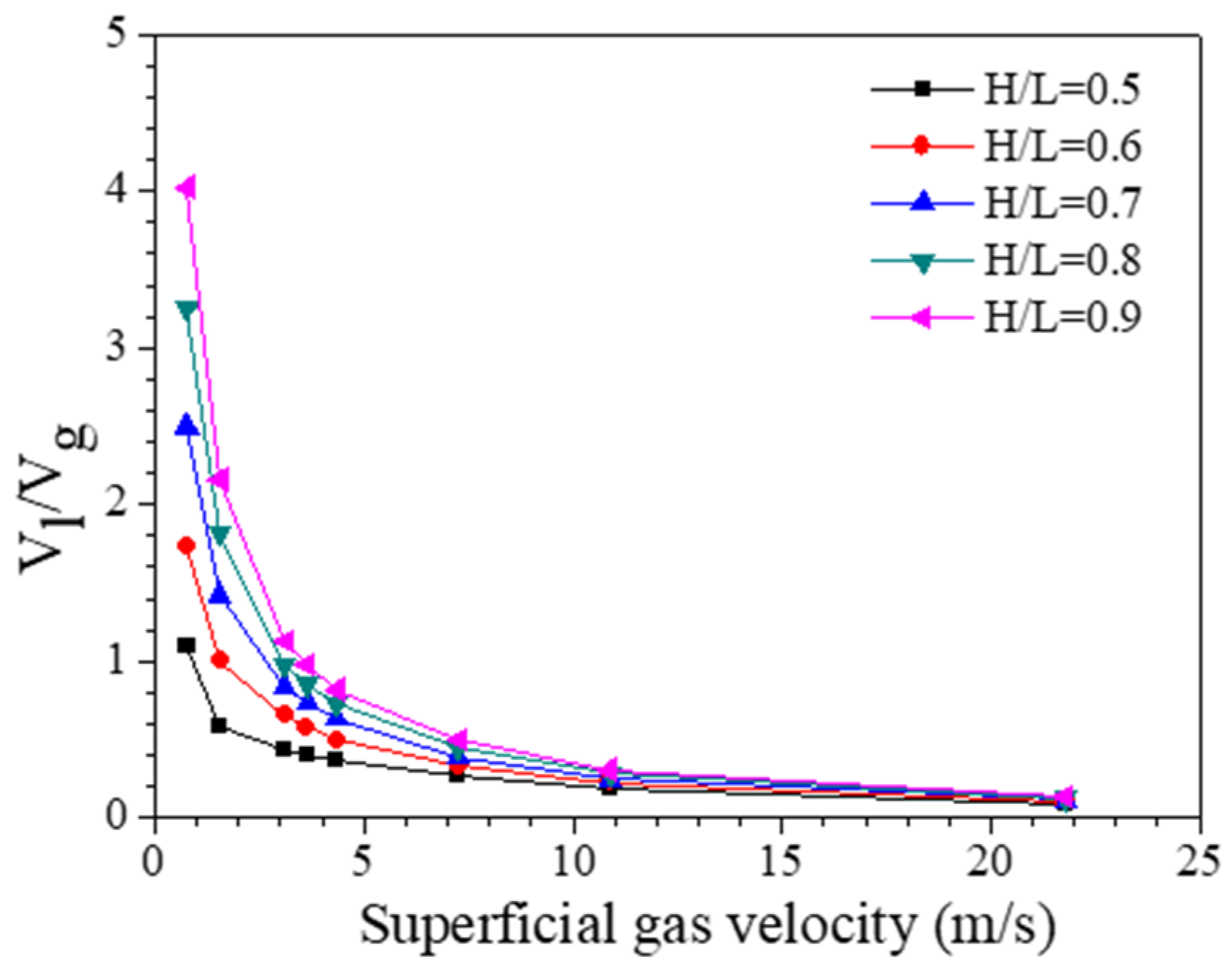
The flow patterns and stripping ratios (Vl/Vg) under different immersion ratios and superficial gas velocities are shown in Figure 10 and Figure 11. Vl and Vg represent the volume flow rate of liquid and gas phase inside a vertical riser, which was obtained by CFD simulations. It can be seen that with the increase of immersion ratio and the decrease of superficial gas velocity, the stripping ratio increases and the flow pattern tends to be bubble flow.
For the design of IC anaerobic reactor, it is necessary to keep the internal circulation flow rate stable. From Figure 8, it can be seen that the most favorable flow pattern is bubble flow. As shown in Figure 9 and Figure 10, the internal circulation flow rate decreases with the increase of the superficial gas velocity when the flow pattern is churn flow. Therefore, the bubble flow pattern can be realized by adjusting the superficial gas velocity and immersion ratio according to Figure 9. Gas stripping ratios can be obtained from Figure 11.

3.2. Gas Holdup of Vertical Riser

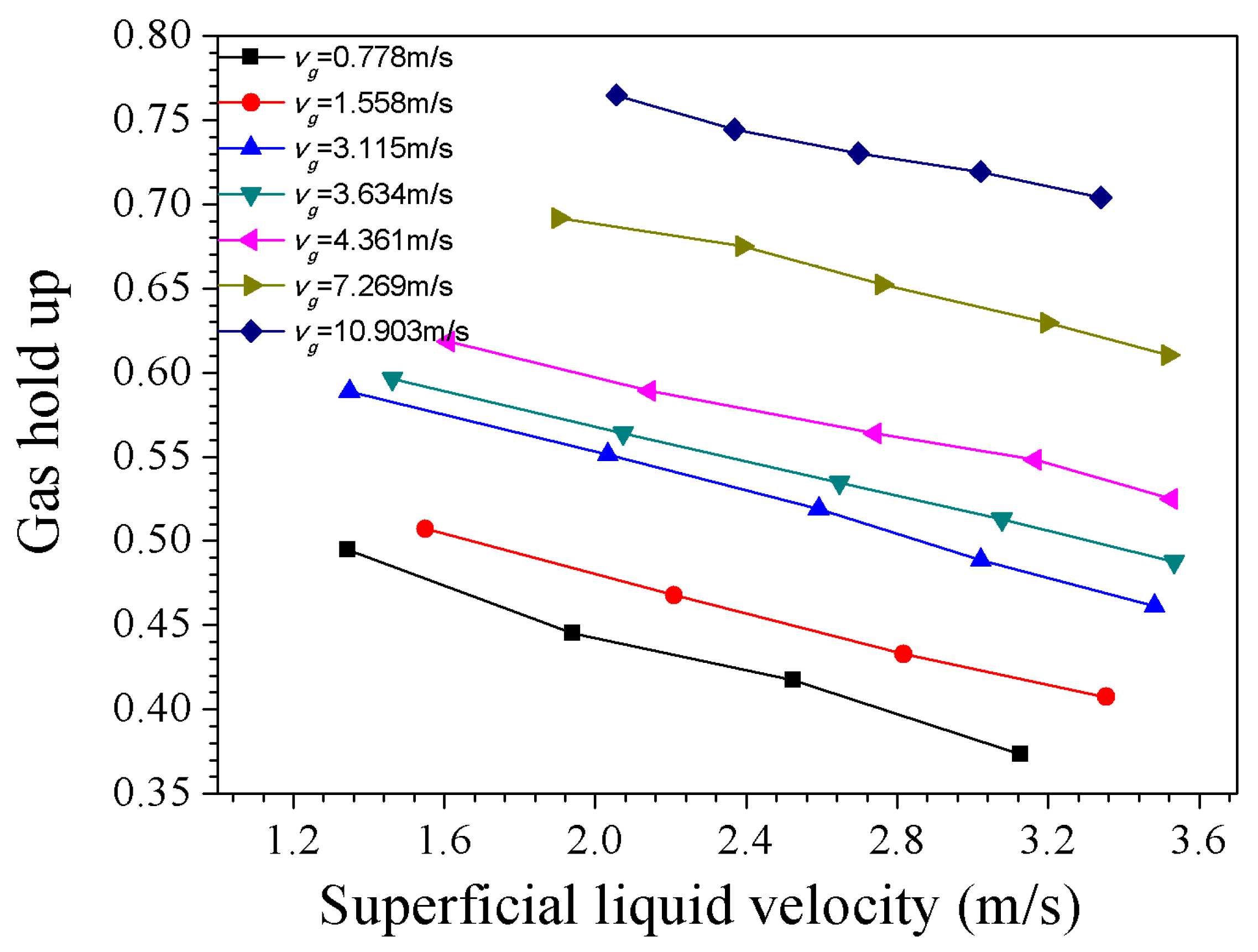
As shown in Figure 12, with the increase of superficial liquid velocity (vl), the gas holdup decreases continuously. There exists approximate linear relationship between the gas holdup and superficial liquid velocity.
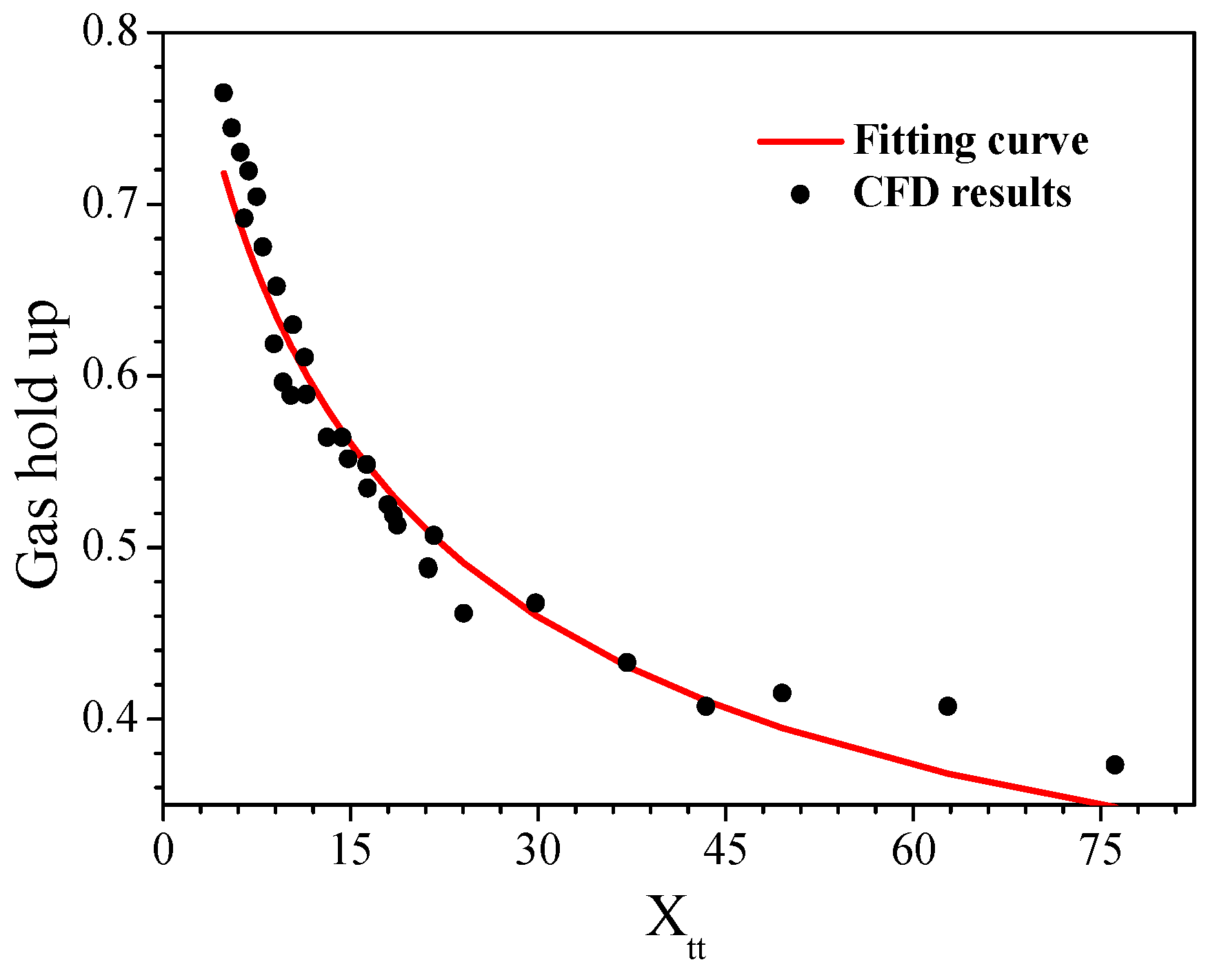
Figure 13 shows the relationship between gas holdup obtained by CFD method and Martinelli parameter ( X t t ). The Martinelli parameter ( X t t ) is given as [24]:
α = 1 ( a 1 X t t 2 + b X t t + 1 ) 0.5
The constants (a and b) are set as 1 and 21, respectively [30]. Based on the CFD simulation results for gas holdup, the Martinelli parameter ( X t t ) is fitted and the improved form is given below:
α = 1 ( 0.6 1 X t t 2 + 31 X t t + 1 ) 0.5
The gas holdup obtained by Hu’s work [2,33] was compared with that by Martinelli and improved gas holdup model (Equation (14)). The calculated deviation for the gas holdup by Martinelli model and the experimental result is 50.2%, while the deviation is 13.7% when calculated by Equation (14). The improved gas holdup model can effectively improve the accuracy of gas holdup prediction in gas–liquid two-phase flow of vertical riser.

3.3. Frictional Pressure Drop of Vertical Riser

The most important contribution of this paper is the improvement of the calculation of the frictional pressure drop. The relationship between gas hold up and the Martinelli parameter ( X t t ) can be given as:
ϕ 2 = 1 + a X t t + ( b X t t ) 2
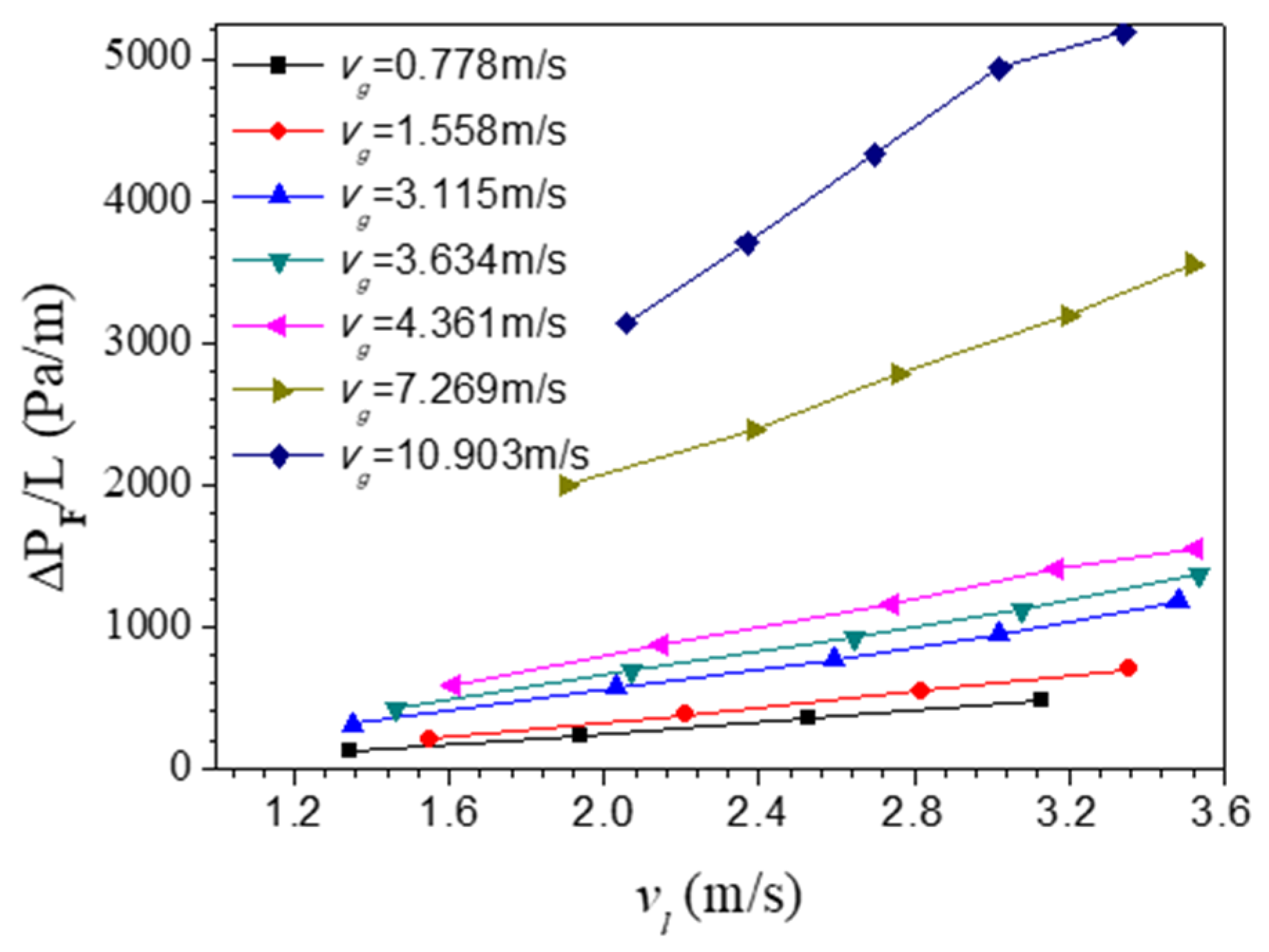
According to the simulation results in Figure 14, the two-phase friction multiplier ϕ 2   (Equation (8)) can be calculated. The relationship between ϕ 2   (Equation (8)) and Martinelli parameter ( X t t ) was plotted as shown in Figure 15. The parameters in Equation (15) of a and b was fitted and the improved two-phase friction multiplier ϕ 2 is given as below:
ϕ 2 = 1 + 35 X t t + ( 20 X t t ) 2
Therefore, the improved frictional pressure drop model consists of Equations (7)–(9) and Equation (16).
The frictional pressure drops calculated by Martinelli model and improved model in this study were compared with the experimental results of Zhou et al. [34]. The deviation between the frictional pressure drop obtained by Martinelli model and the experimental value is 71.7%, while the deviation between the improved model and the experimental value is 13.2%. The improved frictional pressure drop model can significantly improve the accuracy of the prediction of pressure drop in vertical riser.

4. Conclusions

In this study, the hydrodynamic behaviors of riser in IC anaerobic reactor were studied by multiple flow regimes model. The results show that the bubble flow has a smaller fluctuation range and shorter fluctuation period compared with the slug flow and the bulk flow. When the immersion ratio is constant, there is a peak value of liquid flow rate with the increase of superficial gas velocity. According to the analysis of the flow pattern and the liquid flow rate, bubble flow is considered as the best flow pattern in riser. Based on the simulation data, the parameters of Martinelli gas holdup model and the two-phase friction multiplier model have been corrected. Compared with the experimental data, the calculated deviations of the gas holdup by the corrected model are reduced from 44% and 50% to 13.7% and 14.4%, respectively. The deviation between the calculated friction pressure drop and the experimental data is reduced from 71.7% to 13.2%, which effectively improves the accuracy of prediction of the gas holdup and frictional pressure drop of vertical riser. The corrected model can be used to design the internal circulation system and IC reactor.

Author Contributions

Conceptualization and methodology, S.W. and H.D.; writing—original draft preparation, S.W. and Z.G.; writing—review and editing, S.W., H.D., and Z.G.; supervision, X.D.

Funding

This research received no external funding.

Conflicts of Interest

The authors declare no conflict of interest.

Nomenclature

C 1 Primary criteria of the thickness of the raw interface (-)
f Friction factor (-)
F Interphase force (N)
g Gravity (m/s2)
G g Mass flux of gas (kg/m2/s)
G l Mass flux of liquid (kg/m2/s)
H Height from the bottom of the second reaction chamber to the outlet of the wastewater (m)
L Length of the riser (m)
M Weight functions of topological structure (-)
Δ P Pressure drop (Pa)
Δ s Surface area of the cell (m2)
Δ v Volume of the cell (m3)
W g Mass flow rate of gas (kg/s)
W l Mass flow rate of liquid (kg/s)
X t t Martinelli parameter (-)
Greek letters
α Gas holdup (-)
ε Volume fraction (-)
μ g Viscosity of gas (Pa·s)
μ l Viscosity of liquid (Pa·s)
ρ g Density of gas (kg/m3)
ρ l Density of liquid (kg/m3)
ϕ 2 Two-phase friction multiplier (-)
Subscripts
a Accelerational
A Grid A
A B Two lines of the centroids of grid A and grid B
B Grid B
c Phase
f Cell-face
f r First regime
F Frictional
g Gravitational
i Individual component of phase
i r Interface regime
l Liquid
m Mean
m a x Maximum
p Primary
p s Phase interaction
s Secondary
s r Second regime
x Scalar x

References

  1. Wang, Y.; Liu, X.; Zhuang, W.; Zhou, J.; Wang, J. Advance: IC reactor for high strength industrial wastewater treatment and biogas production. In Proceedings of the 2011 International Conference on Materials for Renewable Energy & Environment IEEE, Shanghai, China, 20–22 May 2011. [Google Scholar]
  2. Pereboom, J.H.F.; Vereijken, T.L.F.M. Methanogenic granule development in full scale internal circulation reactors. Water Sci. Technol. 1994, 30, 9–21. [Google Scholar] [CrossRef]
  3. Hu, J. A method of design and calculation for internal circulation (IC) reactor. China Biogas 2011, 29, 3–6. [Google Scholar]
  4. Shannak, B.A. Frictional pressure drop of gas liquid two-phase flow in pipes. Nucl. Eng. Des. 2008, 238, 3277–3284. [Google Scholar] [CrossRef]
  5. Chen, I.Y.; Yang, K.; Chang, Y.; Wang, C. Two-phase pressure drop of air-water and R-410A in small horizontal tubes. Int. J. Multiph. Flow 2001, 27, 1293–1299. [Google Scholar] [CrossRef]
  6. Li, X.; Hibiki, T. Frictional pressure drop correlation for two-phase flows in mini and micro single-channels. Appl. Therm. Eng. 2017, 90, 29–45. [Google Scholar] [CrossRef]
  7. Xiao, B.; Wang, W.; Zhang, X.; Long, G.; Fan, J.; Chen, H.; Deng, L. A novel fractal solution for permeability and Kozeny-Carman constant of fibrous porous media made up of solid particles and porous fibers. Powder Technol. 2019, 349, 92–98. [Google Scholar] [CrossRef]
  8. Xiao, B.; Zhang, X.; Jiang, G.; Long, G.; Wang, W.; Zhang, Y.; Liu, G. Kozeny–Carman Constant for Gas Flow through Fibrous Porous Media by Fractal-Monte Carlo Simulations. Fractals 2019, 27, 1950062. [Google Scholar] [CrossRef]
  9. Long, G.; Liu, S.; Xu, G.; Wong, S.; Chen, H.; Xiao, B. A Perforation-Erosion Model for Hydraulic-Fracturing Applications. SPE Prod. Oper. 2018, 33, 770–783. [Google Scholar] [CrossRef]
  10. Liang, M.; Fu, C.; Xiao, B.; Luo, L.; Wang, Z. A fractal study for the effective electrolyte diffusion through charged porous media. Int. J. Heat Mass Transf. 2019, 137, 365–371. [Google Scholar] [CrossRef]
  11. Navah, F.; Nadarajah, S. A comprehensive high-order solver verification methodology for free fluid flows. Aerosp. Sci. Technol. 2017, 80, 101–126. [Google Scholar] [CrossRef] [Green Version]
  12. Knight, D.; Yan, H.; Panaras, A.G.; Zheltovodov, A. Advances in CFD prediction of shock wave turbulent boundary layer interactions. Prog. Aerosp. Sci. 2003, 39, 121–184. [Google Scholar] [CrossRef]
  13. Xia, H.; Tucker, P.G.; Dawes, W.N. Level sets for CFD in aerospace engineering. Prog. Aerosp. Sci. 2010, 46, 274–283. [Google Scholar] [CrossRef]
  14. Lestinsky, P.; Vecer, M.; Vayrynen, P.; Wichterle, K. The effect of the draft tube geometry on mixing in a reactor with an internal circulation loop-A CFD simulation. Chem. Eng. Process. Process Intensif. 2015, 94, 29–34. [Google Scholar] [CrossRef]
  15. Lestinsky, P.; Vecer, M.; Vayrynen, P.; Wichterle, K. Hydrodynamics of Airlift Reactor with Internal Circulation Loop: Experiment vs. CFD Simulation. Procedia Eng. 2012, 42, 892–907. [Google Scholar] [CrossRef]
  16. Hanafizadeh, P.; Saidi, M.H.; Karimi, A.; Zamiri, A. Effect of Bubble Size and Angle of Tapering Upriser Pipe on the Performance of Airlift Pumps. Part. Sci. Technol. 2010, 28, 332–347. [Google Scholar] [CrossRef]
  17. Abdulkadir, M.; Hernandez-Perez, V.; Lo, S.; Lowndes, I.S.; Azzopardi, B.J. Comparison of experimental and Computational Fluid Dynamics (CFD) studies of slug flow in a vertical riser. Exp. Therm. Fluid Sci. 2015, 68, 468–483. [Google Scholar] [CrossRef]
  18. Hanafizadeh, P.; Moezz, M.; Saidi, M.H. Numerical Modeling of Gas-Liquid Two Phase Flow in Upriser Pipe of Airlift System. In Proceedings of the 8th International Conference on Multiphase Flow, Jeju, Korea, 26–31 May 2013. [Google Scholar]
  19. Ishii, M. Thermo-Fluid Dynamic, Theory of Two-Phase; Eyrolles: Paris, France, 1975. [Google Scholar]
  20. Wallis, G.B. One-Dimensional Two-Phase Flow; Mcgraw-Hill: New York, NY, USA, 1969. [Google Scholar]
  21. Drew, D.A.; Passman, S. Theory of Multicomponent Fluids; Springer: New York, NY, USA, 1998. [Google Scholar]
  22. Gada, V.H.; Tandon, M.P.; Elias, J.; Vikulov, R.; Lo, S. A large scale interface multi-fluid model for simulating multiphase flows. Apply Math Model 2017, 44, 189–204. [Google Scholar] [CrossRef]
  23. STAR-CCM+. Siemens. Available online: http://mdx.plm.automation.siemens.com (accessed on 5 November 2019).
  24. Egorov, Y.; Boucker, M.; Martin, A.; Pigny, S.; Scheuerer, M.; Willemsen, S. Validation of CFD codes with PTS-relevant test cases. In Proceedings of the 5th Euratom Framework Programme ECORA Project, Pisa, Italy, 24–25 September 2004. [Google Scholar]
  25. Höhne, T.; Vallée, C. Modelling of stratified two phase flows using an interfacial area density model. WIT Trans. Eng. Sci. 2009, 63, 123–133. [Google Scholar]
  26. Höhne, T.; Mehlhoop, J.P. Validation of closure models for interfacial drag and turbulence in numerical simulations of horizontal stratified gas–liquid flows. Int. J. Multiph. Flow 2014, 62, 1–16. [Google Scholar] [CrossRef]
  27. Tentner, A.; Lo, S.; Ioilev, A.; Samigulin, M.; Ustinenko, V. Computational fluid dynamics modeling of two-phase flow in a boiling water reactor fuel assembly. In Proceedings of the International Conference on Mathematics and Computations, American Nuclear Society, Avignon, France, 12–15 September 2005. [Google Scholar]
  28. Coste, P. A Large Interface Model for two-phase CFD. Nucl. Eng. Des. 2013, 255, 38–50. [Google Scholar] [CrossRef]
  29. Lin, Z.; Wang, S.; Wang, D. Friction and accelerational pressure drop of gas-liquid in a pipe. In Gas-Liquid Two Phase flow and Boiling Heat Transfer, 2nd ed.; Xi’an Jiaotong University Press: Xi’an, China, 2003; pp. 63–105. [Google Scholar]
  30. Lockhart, R.W.; Martinelli, R.C. Proposed correlation of data for isothermal two-phase, two-component flow in pipes. Chem. Eng. Prog. 1949, 45, 39–48. [Google Scholar]
  31. Chisholm, D. Pressure gradients due to friction during the flow of evaporating two-phase mixtures in smooth tubes and channels. Int. J. Heat Mass Transf. 1973, 16, 347–358. [Google Scholar] [CrossRef]
  32. Eppinger, T.; Seidler, K.; Kraume, M. DEM-CFD simulations of fixed bed reactors with small tube to particle diameter ratios. Chem. Eng. J. 2011, 166, 324–331. [Google Scholar] [CrossRef]
  33. Hu, J.; Hu, X. Calculation of internal circulation flow rate of internal circulation anaerobic reactor. China Water Wastewater 2012, 28, 95–98. [Google Scholar]
  34. Zhou, Y.; Ding, H. Experiment study on Gas-liquid two-phase flow in Rod Bundle Channel. At. Energy Sci. Technol. 2016, 50, 1776–1781. [Google Scholar]
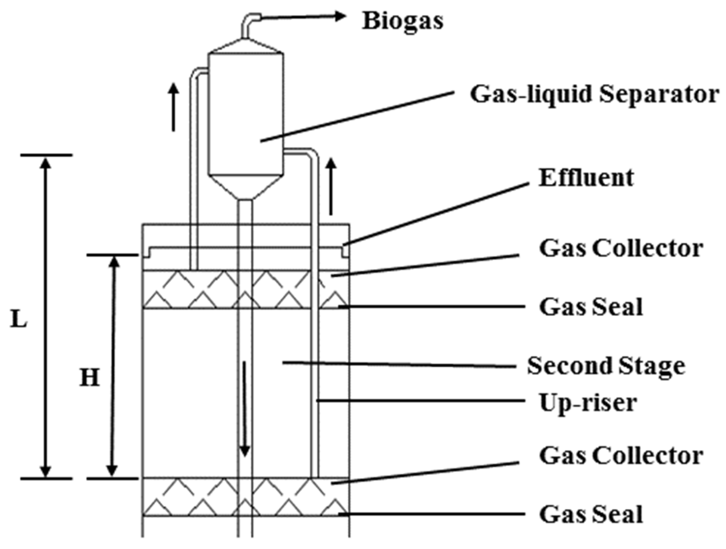
Figure 1. Schematic diagram of internal circulation system for Internal Circulation (IC) reactor.
Processes 07 00936 g001
Figure 2. Variation of weight function values with volume fraction of secondary phase.
Processes 07 00936 g002
Figure 3. Geometric model of internal circulation system.
Processes 07 00936 g003
Figure 4. The relationship between liquid flow rates and base mesh sizes.
Processes 07 00936 g004
Figure 5. Mesh topology of computational domain.
Processes 07 00936 g005
Figure 6. Distributions of gas holdup under different superficial gas velocities (H/L = 0.7).
Processes 07 00936 g006
Figure 7. Distributions of gas holdup under different immersion ratios (vg = 4.361 m/s).
Processes 07 00936 g007
Figure 8. Liquid flow rates at different time. H/L = 0.6 vg = 3.115 m/s (A), vg = 3.634 m/s (B), and vg = 10.903 m/s (C).
Processes 07 00936 g008
Figure 9. Liquid flow rate under different superficial gas velocities and immersion ratios.
Processes 07 00936 g009
Figure 10. Flow patterns at different immersion ratios and superficial gas velocities.
Processes 07 00936 g010
Figure 11. Gas stripping ratios V l / V g at different immersion ratios.
Processes 07 00936 g011
Figure 12. Gas holdup for different superficial liquid and gas velocities.
Processes 07 00936 g012
Figure 13. Gas holdup as a function of Martinelli parameter ( X t t ).
Processes 07 00936 g013
Figure 14. Δ P F as a function of superficial liquid velocity and gas velocity.
Processes 07 00936 g014
Figure 15. Two-phase friction multiplier ϕ 2 as a function of Martinelli parameter X t t .
Processes 07 00936 g015